PHYS 406, Spring 2016 - courses.physics.illinois.edu · My enrollment in this course, and the...
16
PHYS 406, Spring 2016 Final Report Refurbishing a 1960’s Teisco “Melody” Tube Amplifier By Alex Taylor 05/11/2016 1
Transcript of PHYS 406, Spring 2016 - courses.physics.illinois.edu · My enrollment in this course, and the...

PHYS 406, Spring 2016 Final Report
Refurbishing a 1960’s Teisco “Melody” Tube Amplifier
By Alex Taylor 05/11/2016
1
Introduction:
My enrollment in this course, and the genesis of the following project, came about
from a string of unlikely coincidences. The first of which came about in a geology class I
was taking in the spring of 2014. I was explaining to a physics major that I had always
wanted to learn more about the physics behind common analog audio gear, namely tape
recorders and tube amplifiers. The student then told me they were enrolled in a class,
PHYS 406, which was taught by a tube amplifier phanatic. Prompted by genuine interest,
I decided to dig into what this class was all about. This led me to me to Dr. Errede’s
PHYS 406 website, where I learned about his involvement with Analog Outfitters.
I then looked up this Champaign based company, only to find out they were
having a sale later in the week. I attended the sale and found a tube amp that clearly
wasn’t working, as the circuit housing was dusty, oxidized and sitting at the base of the
speaker cabinet, completely disconnected and missing tubes. After taking it home, I
quickly realized that refurbishing the amp was way out of my league. So, it sat in my
closet for a year until I was able to enroll in PHYS 406 and received permission from Dr.
Errede to refurbish the the amp and take some basic acoustical measurements for my
semester long project.
2

Amp Background:
The tube amplifier shown above is a 1960’s Teisco Melody. This amplifier has a
10” speaker, four ¼” inputs, a footswitch input (which was missing when purchased), and
three control knobs (volume, tone and tremolo speed). Teisco was a Japanese company
that made audio gear including amplifiers, drums, keyboards and most famously, guitars
3

between the 1960’s and 1980’s. Some of the musicians that popularized Teisco guitars
were Hound Dog Taylor, Jim Reid of The Jesus and Mary Chain and James Iha of The
Smashing Pumpkins.
After identifying the make and model, I tried to find a circuit diagram for the amp
online. This search proved unsuccessful at first, until I realized that this particular amp
was produced and sold under various names, one of which was the Beltone APA.
Luckily this amp is identical to the Teisco Melody in terms of circuitry and basic design.
Furthermore, a circuit diagram for the Beltone APA can easily be found on the internet
and is shown below:
4

Tube Amp Basics:
Almost all tube amplifiers function on the same fundamental principles. The
amplifier is powered by 120V of alternating current from a wall outlet, which is supplied
to the power transformer. This is in turn distributes electricity to each of the heating
elements in the cathode of each vacuum tube and specifically to the rectifier tube (6X4 in
the diagram above). This rectifying tube serves the crucial role of transforming the
incoming AC current, to the DC current. The DC current that leaves the rectifier tube
then flows through the electrolytic capacitor, which smoothes out the DC current and
distributed electricity in fixed proportions between points A, B and C in the diagram
above. The specifications of the electrolytic capacitor, and the remaining circuit in
general, vary from amp to amp.
The signal supplied to the amplifier through the ¼” input (typically from a guitar)
passes through the circuit and first encounters the preamp tubes (6AV6 in the diagram
above). These vacuum tubes serve a primary purpose of amplifying the signal to levels
which can be manipulated by the volume, tone and tremolo potentiometers. Next, the
signal is supplied to the power tube (6AQ5 in the diagram above) which further amplifies
the signal, but this time to audible levels which can be supplied to the output transformer.
It is worth noting that all vacuum tubes function on the same basic principles. A
heating element in the cathode supplies the energy necessary to force electrons to flow
off the cathode, which are then attracted to the anode. Between the cathode and anode is a
wire grid, which has its own voltage and thus controls the rate at which the electrons can
5

flow between the cathodeanode gap. Furthermore, this processes produces distortion in
the audio signal as it passes through the vacuum tube. The distortion produced is what
gives tube amplifier their characteristic, warm sound. Because not all vacuum tubes have
the same specifications and design, different tubes distort, or “color”, the sound
differently . This is why specific tube amplifiers become so collectible and appreciate in
value over time. Additionally, the distortion produced by a tube amplifier is directly
proportional to the amount of signal passing through the tube. At high volumes the tubes
are able to “color” the signal to their maximum potential (a coincidental gift to early punk
rock and rock ‘n’ roll). This is why turning the volume up as high as possible on a tube
amp (without blowing the speaker) yields the highest sound quality.
As stated previously, the signal leaving the power tube goes to the output
transformer, which uses high voltage to bring the final processed signal up to the bias of
the speaker (8 ohms for the speaker in my Teisco Melody). Then, the signal provided to
the speaker leads force the magnetic flux produced by the speaker's magnet to
periodically reverse, causing the speaker’s voice coil to oscillate in the magnet’s gap and
drive the speaker cone to compress air such that the electrical energy supplied by the
output transformer is turned into acoustic energy.
6

Modifications:
As stated previously, the amplifier was nowhere near functional when I bought it.
The power cord was completely cut off and the circuit chassis was detached and sitting at
the base of the speaker cabinet. Furthermore, only the three 6AV6 vacuum tubes were
provided.
The first step in restoring this amp was checking if the circuit diagram matched
the circuit within the chassis (paying special attention to the wiring on each vacuum tube
pin). I also tested each of the resistors with a voltmeter to see if they were functioning
properly. Luckily most of the components were functional and in their correct locations,
aside for the fuse/power switch arrangement. Additionally, the only nonoriginal
component was the power switch, which had clearly been replaced by the previous
owner.
Thus, the first modification involved replacing the power cord and rearranging the
placement of the power switch such that it sat between the fuse and power cord. This
insures that a malfunction in the power supply won’t fry the power transformer or any of
the components farther along in the circuit.
Next, we replaced the original electrolytic capacitor. This is usually the first
component within a tube amp to give out, as they only function for a given number of
playing hours. Furthermore, given that this component was 50+ years old, it’s fair to
assume it needed to be replaced. We also added a screen resistor between the electrolytic
capacitor and the power tube (6AQ5 in the diagram above). This additional resistor puts a
7
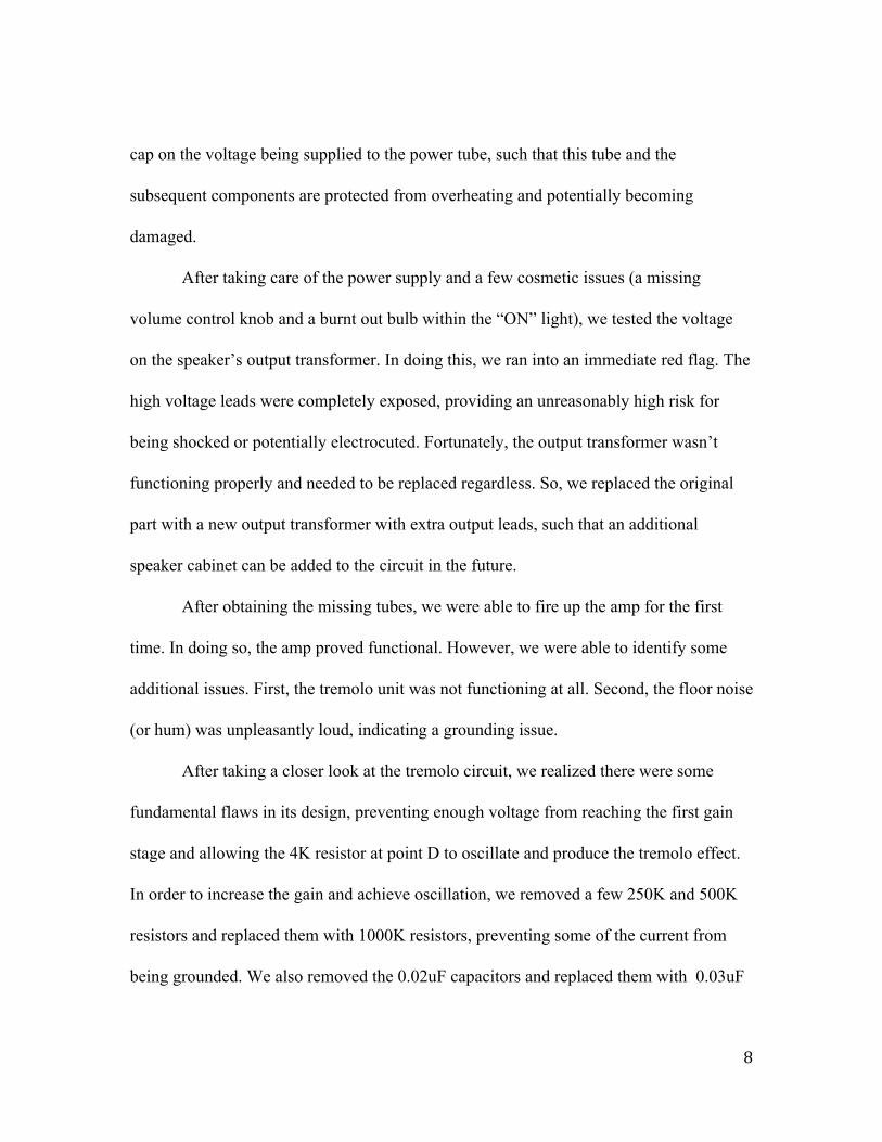
cap on the voltage being supplied to the power tube, such that this tube and the
subsequent components are protected from overheating and potentially becoming
damaged.
After taking care of the power supply and a few cosmetic issues (a missing
volume control knob and a burnt out bulb within the “ON” light), we tested the voltage
on the speaker’s output transformer. In doing this, we ran into an immediate red flag. The
high voltage leads were completely exposed, providing an unreasonably high risk for
being shocked or potentially electrocuted. Fortunately, the output transformer wasn’t
functioning properly and needed to be replaced regardless. So, we replaced the original
part with a new output transformer with extra output leads, such that an additional
speaker cabinet can be added to the circuit in the future.
After obtaining the missing tubes, we were able to fire up the amp for the first
time. In doing so, the amp proved functional. However, we were able to identify some
additional issues. First, the tremolo unit was not functioning at all. Second, the floor noise
(or hum) was unpleasantly loud, indicating a grounding issue.
After taking a closer look at the tremolo circuit, we realized there were some
fundamental flaws in its design, preventing enough voltage from reaching the first gain
stage and allowing the 4K resistor at point D to oscillate and produce the tremolo effect.
In order to increase the gain and achieve oscillation, we removed a few 250K and 500K
resistors and replaced them with 1000K resistors, preventing some of the current from
being grounded. We also removed the 0.02uF capacitors and replaced them with 0.03uF
8
capacitors. This made enough of a difference in the circuit to yield oscillation in the first
gain state and produce a tremolo effect.
Finally, we noticed that each of the four ¼” input jacks had a wire running
between the jack and a four pronged terminal. This terminal was then connected to pin 1
in the first gain stage by another group of four wires that were twisted together and
secured by a heat shrink cover. The large amount of wiring used in making this
connection produced an antenna effect that was creating the large amount of hum (even
picking up radio broadcast when the inputs were floating). So, to reduce that amount of
wiring, we bypassed the four pronged terminal and connected the input jacks to the first
gain stage by the single grouping of wires in the heat shrink cover. Dr. Errede also
repositioned the grounding such that the ¼” jacks float (ungrounded) until a ¼” jack is
inserted. Thus, there is still a noticeable amount of hum when the jacks are floating, but
the hum is minimal once an input jack has been inserted.
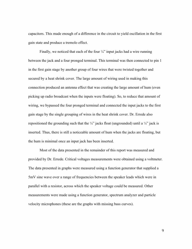
Most of the data presented in the remainder of this report was measured and
provided by Dr. Errede. Critical voltages measurements were obtained using a voltmeter.
The data presented in graphs were measured using a function generator that supplied a
5mV sine wave over a range of frequencies between the speaker leads which were in
parallel with a resistor, across which the speaker voltage could be measured. Other
measurements were made using a function generator, spectrum analyzer and particle
velocity microphones (these are the graphs with missing bass curves).
9

Critical Voltage Measurements (original circuit): GRID, Pin 1 CATHODE, Pin 2 PLATE, Pin 7 6AV6, 1st Gain Stage 0.031 0.923 130.0 6AV6, 2nd Gain Stage 0 1.303 146.8
6AV6, Tremolo 0 OFF: 2.6 ON: 1.478 OFF: 176 ON: 139 6AQ5, Power Tube 0.038 17.92 302.3
P420Ω DISS 0.76 Watts P6AQ5 DISS 12.23 Watts (ABS max)
I420Ω 0.043 A P6AQ5 K 43 mA (DC)
VB+ = VA 309.8 V6AQ5SCR = VB 268.4
VC 193.6
VLINEAC 119.4 VMAIN SECONDARY
AC 542 VPREAMP HTRS
AC 6.52 V6X4 HTR AC 6.55
10

Graphs:
Speaker impedance
11
Complex Voltage Measurements
12

Complex Power Measurements
13

Pressure Measurements Using Particle Velocity Microphones
14

Current Measurements Using Particle Velocity Microphones
15

Online References Describing Teisco History:
https://en.wikipedia.org/wiki/Teisco
http://www.larryjohnmcnally.com/Teisco/
16