PHYS 2421 - Fields and Waves - Academics Portal Index 2421/class material...Horizontal projection...
34
PHYS 2421 - Fields and Waves
Transcript of PHYS 2421 - Fields and Waves - Academics Portal Index 2421/class material...Horizontal projection...

PHYS 2421 - Fields and Waves

cosi I t
Idea: how to deal with alternating currents
Edison wanted direct current, Tesla alternating current, who won?
Mathematically:
Instantaneous current:
Instantaneous voltage:
w is the angular frequency
w=2pf, f = 60 Hertz (50 Hertz in Europe)
V=120 volts (220 in Europe, South America)
Symbol in circuits:
cosv V t
Average I ?: 0Avei
How to measure a changing current?
There are several ways.

cosi I tHow to characterize alternating currents?
Average of rectified I ?: 2 / / 2
0 / 2
2
0
22
0.6372
cos cos
rav
t t
t t
t
t
dt I dI
I
dt
I t
I
Method 1: Rectified average
iUse average of

cosi I tHow to characterize alternating currents?
2 2 /
2
0 0
1
2cos2
2
Ave
t t
t t
I dt dt
i
t
2
2
0
1
2 2rmst
t
II
dt
I
Method 2: Root mean square average
2iUse average of
Average of ?: 2i
2 2 2 2 1
2cos 1 cos2i I t I t
2
rms AveiI
0.7071rms I I 0.637rav II Compare to

cosi I tHow to characterize alternating currents?
Method 3: Phasor
• Take instantaneous current as component of a vector
• Let vector rotate with angular speed .
• Useful for comparing times
Let us see some examples
Not a Mexican Wrestler!

0Avea) I
2.7rms
Given:
AI
22 2.7 7.3i iI I 2 2 2
rms Ave rmsAve
A Ab)
2.7 2 2 2.7 3.82
rms rms A A Ac) I
I I I
Hmwk: Probls 11th ed.: 31.1 and 2 (soln.: 2.97 A and 1.89 A)
or 12th Ed.: 31.3 and 2

Summary of Section 31.1
cosi I tSymbol in circuits:
cosv V t
Average I ?: 0Avei
2rav II
2rms
II
Phasor
Hmwk Sect. 31.1: Probls 11th ed.: 31.1 and 2
or 12th Ed.: 31.3 and 2

cos
cos
R
R
v iR
IR t
V t
Phasor diagram
Resistor in an ac circuit
Voltage drop across R?
cosi I t

cosi I t
cos
sin
cos 90
cos 90
L
o
o
L
d Idi
dt dt
tv L L
I L t
I L t
V t
Phasor diagram
Inductor in an ac circuit
L
L
is like a resistance,
call it "Reactance"
Inductive reactance
V I L L
X L
Voltage drop across L?
Reactance

a) Want XL to have i=250 mA when V=3.6 V610/ 3.6 /250 14.4L L L L A V kV IX X V I
Now want L
3 610 1.6 10 1.43
2
/ 2 14.4 / 2
L
L mH
X L fL
L X f
b) Want I for 16 MHz and 160 kHz / / 2L L L
As increases by 10, decreases by 10 I=25 A
As decreases by 10, increases by 10 I=2500 A
I V X V fL
f I
f I
m
m
Hmwk: Probls 31.3 and 5 (11th Ed) or 5 and 9 (12th Ed.)
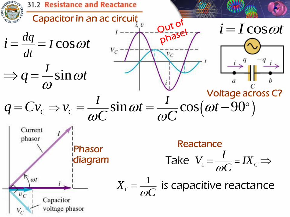
cos
sin
sin cos 90o
C C
dqI
dt
I
I I
i t
q t
q Cv v t tC C
Capacitor in an ac circuit
1
IV IX
C
XC
L C
C
Take
is capacitive reactance
Phasor diagram
cosi I t
Voltage across C?
Reactance

Hmwk: Probls
11th Ed.: 31.7 & 10 Soln: a) 1736 W, vR=1.10cos [120t]
12th Ed.: 31.11 & 12 Soln: a) 1736 , vR=1.10cos [120t]
1.2 cos 25000.006cos 2500
200
Aa) A
tvi t
R
1 1
8062500 5 10
C rad/s F
b) XC
/ 2 0.48 2500 / 2cos cosC C V rad/sc) t tv V

Summary of Section 31.2
cosR Rv V tR in an ac circuit
cosi I t
cos 90o
L Lv V t
Reactance
L in an ac circuit
LX L
Reactance
C in an ac circuit
cos 90o
C
Iv t
C
1CX
C

Summary of Section 31.2
Homework for section 31.2:
11th Ed.: Probls 3, 5, 7 and 10
12th Ed.: Probls 5, 9, 11 and 12

cosR Rv V t
cosi I t
cos 90o
L Lv V t
cos 90o
C
Iv t
C
i and vR are in phase
vL is ahead 90o
vC is behind 90o
At this point phasors become useful

vL is ahead 90o
vC is behind 90o
vR is in phase with i
v across source?
v v v v R L C
cos cos 90 cos 90I
v V t V t tC
o o
R L
Horizontal projection Horizontal projectionHorizontal projection

Sum of horizontal projections of vectors
= horizontal projection of sum of vectors
Sum voltage vectors:
Magnitude of sum :
2 2 2 22 2
2 22 2; 1/ impedance " " is
R L C L C L C
L C
V V V IR IX IX R X X
IZ Z R X X R L C
V I
Phase angle : tan L C L C L C
R
V V IX IX X X
V IR R
In conclusion, if the current is :
The source voltage is :
cosi I t
cosv IZ t
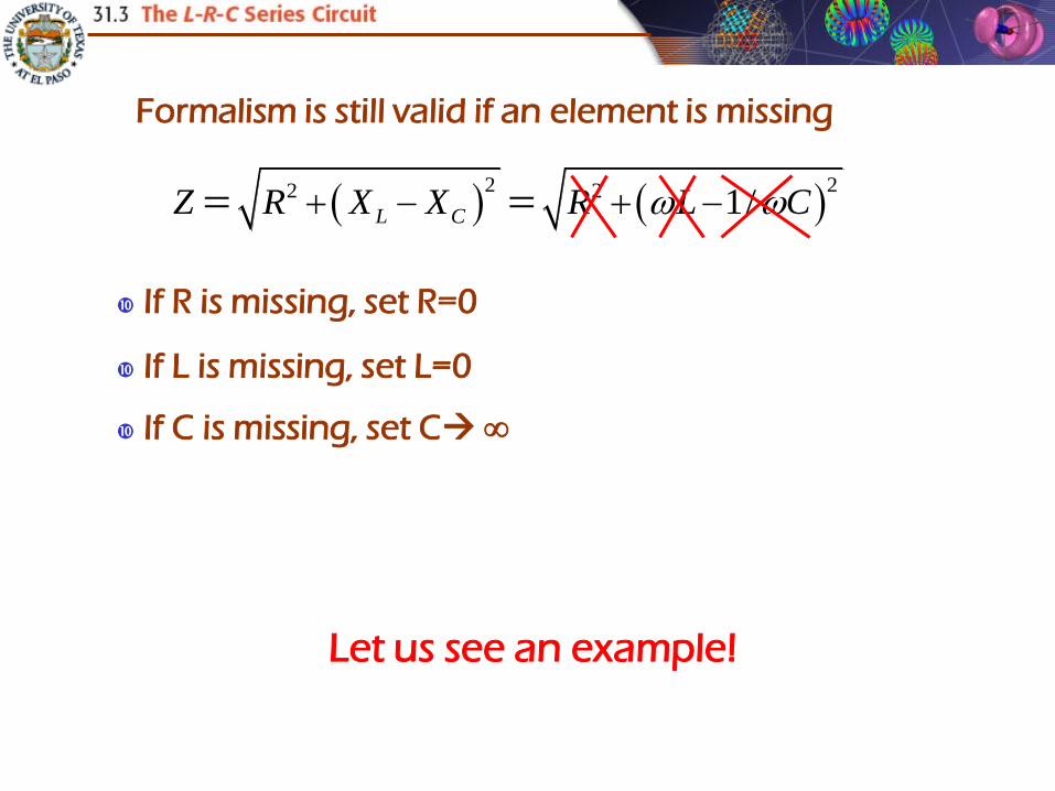
If R is missing, set R=0
Let us see an example!
2 22 2 1/L CZ R X X R L C
If L is missing, set L=0
If C is missing, set C
Formalism is still valid if an element is missing

10,000 60 600L rad/s mH LX
61/ 1/ 10,000 0.5 10 200C rad/s F CX
2 22 2300 600 200 500 L CZ R X X
500.1
500
V A
VI
Z
1 1 0600 200tan tan 53
300
L CX X
R
0.1 300 30 0.1 600 60
0.1 200 20
A V; A V
A V
R L L
C C
IR IX
IX
V V
V
Hmwk: Problem 31.12 (11th Ed.) or 14 (12th Ed.)

cos 30 cos 10,000R V rads/siR IR t tv
Hmwk: Problem 31.13 (11th Ed.) or 16 (12th Ed.)
0cos 90 sin 60 sin 10,000L V rads/sL L LiX V t V t tv
0cos 90 sin 20 sin 10,000C V rads/sC C CiX V t V t tv
0
0cos 50 cos 10,000 53
180 V rads/sV t tv
Instantaneous source voltage
cos 0.1 cos 10,000i I t t A rads/s

Summary of Section 31.3
Hmwk Sect. 31.3: Probls 31.12 & 31.13 (11th Ed.) or 14 & 16 (12th Ed.)
2 22 2 1
1/ ,L C L CZ R X X R L C X L XC
I is mpedance
Phase angle : tan L C L C L C
R
V V IX IX X X
V IR R
If the current is :
The source voltage is :
cosi I t cosv IZ t
cosR IR tv 0 0cos 90 cos 90L LV t IX tv L
0 0cos 90 cos 90C CV t IX tv C
cosV tv Instantaneous source voltage
Voltages across elements:


Idea: vary to increase current
22
L C
V VI
Z R X X
I increases as Z decreases
Z varies with
0
1/
1
L CX X L C
LC
Minimum of Z when XL=XC
“Resonanting frequency”
22 1/Z R L C
Max. I at 0
XL & XC vary with

6 35 10 0.4 10 2000b) rad/s H LX L
6 121/ 1/ 5 10 100 10 2000 rad/s F CX C
2 22 2 2000 2000 500 L CZ R X X R R
12
500
Vc) mA
rmsrms
Vi
Z
0.002 500 1d) A Vrms R rmsV I R
4 Vrms L rms LV I X 4 Vrms C rms CV I X
0
3 12
1 15,000,000
0.4 10 100 10LC
a) rad/s
H F

Summary of Section 31.5
Hwk for sect. 31.5: Probs 27 a)& b) and 32 (11th Ed.)or 31a)& b) and 36 (12th Ed.)
Solution of 32/36: 945 rad/s, 70.6 , 450 V
I output is max at resonance0
1
LC Max. I
at 0L CX X Z R
rmsrms
Vi
Z
rms R rmsV I R
rms L rms LV I X
rms C rms CV I X

Idea: Use an ac circuit at a given v and i to induce a different i and v in another circuit
Add a magnetic core
Add a secondary
loop
Start with a circuit with
i and v
1 1 1 2 2 2I B B I
A changing current I1 induces a changing current I2

Relations between currents and voltages
1 1Bd
Ndt
Notice that the frequency is the same on both circuits
2 2Bd
Ndt
where is the flux per turn (equal on both sides of core)
B
1 2 22 1
1 2 1
Bd NV V
dt N N N
Assuming no resistance in wires
Power-in in circuit 1 = power-out in circuit 2
1 11 1 1 2 2 2 2 1 2 1
2 2
or V N
P I V P I V I I I IV N

2 2
1 1
2402
120
Va) Use a tranformer with
V
N V
N V
12 1 1
2
b) Current: cannot use as is not knownV
I I IV
1 1 2 2
2 1
2 1
960 9604 8
240 120
Must use
W W A or A
V V
P I V I V
P PI I
V V
2 2
2 2/ 240 / 4 60
c) Resistance: take
V A
V RI
R V I
Hmwk: Probl 33 (11th Ed.) or 37 (12th Ed.)

Summary of Section 31.6
Hmwk Section 31.6: Probls 32 and 33 (11th Ed.)
or 36 and 37 (12th Ed.)
Frequency is the same on both circuits
22 1
1
NV V
N
Power-in in circuit 1 = power-out in circuit 2
1 1 1 2 2 2P I V P I V
1 12 1 2 1
2 2
or V N
I I I IV N

PHYS 2421 - Fields and Waves


You got what
grade?


You got what
grade?