PHYS 212 Final Exam (Old Material) Solutions - Practice...
13
PHYS 212 Final Exam (Old Material) Solutions - Practice Test 1E If the ball is attracted to the rod, it must be made of a conductive material, otherwise it would not have been influenced by the nearby positive charge. The reason it is then attracted to the rod is due to “induction”, where the electrons rearrange themselves to be as close to the positive charge as possible (or as far away from the negative charge if the rod was negatively charged). Thus we pick answer choice E. 2A Remember that according to Coulombs Law the force acting on each sphere will be equal in size but acting in opposite directions. This is why they repel. Since the forces acting on each sphere have the same magnitude, and since the spheres have the same mass as well, the acceleration acting on each sphere will also be the same (this is comes from Newton’s second law: F = ma). Thus if they each experience the same acceleration, they will move the same distance apart from each other, and answer choice A is the correct choice depicting that. 3E We use Coulomb’s law to determine the force on the negative charge due to the other two charges located on either side: The force due to the +50μC charge is: where the distance is 2m based on the location of each charge along the x-axis. The force due to the +30μC charge is: where the distance is 2m based on the location of each charge along the x-axis. Thus the net force is F1 +F2 = (-4.495 + 2.697) = -1.798 N along the x-axis. F 1 = k (50μC)(40μC) 2 2 = 4.495N, in the - x direction F 2 = k (30μC)(40 μC) 2 2 = 2.697 N, in the + x direction
Transcript of PHYS 212 Final Exam (Old Material) Solutions - Practice...
PHYS212FinalExam(OldMaterial)Solutions-PracticeTest
1E Iftheballisattractedtotherod,itmustbemadeofaconductivematerial,otherwiseitwouldnothavebeeninfluencedbythenearbypositivecharge.Thereasonitisthenattractedtotherodisdueto“induction”,wheretheelectronsrearrangethemselvestobeasclosetothepositivechargeaspossible(orasfarawayfromthenegativechargeiftherodwasnegativelycharged).ThuswepickanswerchoiceE.2ARememberthataccordingtoCoulombsLawtheforceactingoneachspherewillbeequalinsizebutactinginoppositedirections.Thisiswhytheyrepel.Sincetheforcesactingoneachspherehavethesamemagnitude,andsincethesphereshavethesamemassaswell,theaccelerationactingoneachspherewillalsobethesame(thisiscomesfromNewton’ssecondlaw:F=ma).Thusiftheyeachexperiencethesameacceleration,theywillmovethesamedistanceapartfromeachother,andanswerchoiceAisthecorrectchoicedepictingthat.3EWeuseCoulomb’slawtodeterminetheforceonthenegativechargeduetotheothertwochargeslocatedoneitherside:Theforceduetothe+50µCchargeis:
wherethedistanceis2mbasedonthelocationofeachchargealongthex-axis.Theforceduetothe+30µCchargeis:
wherethedistanceis2mbasedonthelocationofeachchargealongthex-axis.ThusthenetforceisF1+F2=(-4.495+2.697)=-1.798Nalongthex-axis.
€
F1 =k(50µC)(40µC)
22 = 4.495N, in the - x direction
€
F2 =k(30µC)(40µC)
22 = 2.697N, in the + x direction

4DThegeneralequationforelectricfieldisE=F/Q,whererepresentsatestchargeplacedinthefield.Soifwesolvethisequationforforce,weget: F=EQ=(200)(-1.6x10⁻¹⁹)=-3.2x10⁻¹⁷Thechargeisbasedonthechargeofanelectron(givenonyourtest’sdatasheet)andsinceitisnegative,itmusttravelintheoppositedirectionofthefield,thuswechooseanswerchoiceD.5AToanswerthis,wemustuseCoulomb’slawtodeterminethemagnitudeanddirectionofeachforceactingonq1fromtheothercharges:
Notethatweknowtheforcefromq3is300abovethe–xaxissinceallthechargesformanequilateraltriangle60degreesapart.Inordertogetthecorrectmagnitude,wemustfirsttaketheforcesandplacethemintherespectivex-andy-components: F12isalreadyalongthey-axis,soneednotbealtered. F13,xaxis=F13cos30=1.56N,F13,yaxis=F13sin30=0.899NThususingvectoranalysisweseethatthetotalforcealongeachaxisis:
y-axis:0.899+0.899=1.798Nx-axis:1.56N
ThemagnitudeusingPythagoreantheory: ThuswechooseanswerchoiceA.
€
F12 =k(20µC)(20µC)
22 = 0.899N, in the + y axis
F13 =k(20µC)(40µC)
22 =1.798N, 30o above the - x axis
€
F = (1.798)2 + (1.56)2 = 2.38N
6EAswesawduringthereview,wecanbreakdownthe3Qchargesothatitisdistributedevenlyacrossthethreequadrants.Thepurposebeingthatwecanstarttousesymmetrytohelpanalyzetheresultantelectricfield.Theleftrodsimplyhasachargeof1QlocatedalongtheTop-Rightquadrant.Ifwedistributethe3Qchargeevenly,itwouldlookasthoughwehaveachargeof1QalongtheTop-Leftquadrant,achargeof1QalongtheTop-Rightquadrant,andachargeof1QalongtheBottom-Rightquadrant.Althoughwedon’thaveanexactvaluefortheelectricfieldproducedduetoeachquadrant,wecanassumethatthefieldsfromtheTop-LeftandBottom-Rightquadrantswillcanceleachotherout(sinceelectricfieldsarevectors)andthusweareleftwithjusta1QchargeintheTop-Rightquadrant,whichisexactlywhatwehaveintheoriginalleftrod,andthustheirfieldsarethesamestrength.7ESincetheseareinsulatingsheets(notconducting)thechargewillbeemittedfromeachsideofthesheetandtravelevenlyineachdirection.ThusthefieldinregionsIIandIIIwillbenon-existentsincethevectorsfromeachsheetwillcanceloutinthoseregions.OnlyinregionsIandIV,willtheelectricfieldnotcanceloutandthereforebestrongest.8AWherethedensityofthefieldlineshasbeenhalved,wecanassumetheelectricfieldishalfitsoriginalvalue.Sincetheforceisproportionaltothefieldstrength,whenthefieldishalved,sotooistheforce,thusitbecomes5pN.Also,sincewehaveswitchedfromaprotontoanelectron,thechargehasflippedandsotoomustthedirectionoftheforce,thuswemovetotherightinsteadoftheleft.9CAccordingtothepacket,forasolidinsulatingcylindertherearetwoequationsweusefordeterminingelectricfieldbasedonwhetherweareinsideoroutsidethecylinder.Accordingtotheequations,wefindthatinsidethecylinderthefieldincreaseslinearly,andoutsidethecylinderitdecreasesasymptotically.ThusonlyanswerchoiceCfollowsthispattern.10DThistypeofproblemneedsalittlevisualizationbeforetryingtosolve.Anyelectricfieldmovingthroughtheyzplaneisactuallyheadedalongthex-axis.Oncewecanseethat,wecancalculatethespecificfluxusingtheequationF=EA=(24)(2)=48.Notethatweusethex-componentfortheelectricfield,24iN/C.
11EThemosteffectiveuseofGauss’Lawisthatthetotalfluxthroughanenclosedsurfaceisgivenbytotalinternalcharge,q,dividedbytheconstante0.Sincewearenotgiventhetotalcharge,wecansubstituteforitusingq=lL,wherethechargedensity,l,isq/L.ThuswecanpickanswerchoiceEtorepresentthetotalflux.12CForanyconductingsphericalshell,theinsidesurfacewillhavethesamechargeasthepointchargeinsidethespherebutwillhavetheoppositesign.Thustheinnersurfacemustbe-5µC.However,sincethe+5µCinsidethesphereisnotlocatedatthecenter,thechargewillnotbeuniformlydistributedalongtheinnersurface.Anotherruleforconductingsphericalshells,isthatthesumoftheinnerandoutersurfacechargesmustequaltheexcesschargeofthesphere.Soweget:
Inner+Outer=Excess-5µC+Outer=+3µCOuter=+8µC
Theoutersurfacechargewillbeuniformlydistributed,unliketheinnersurfacecharge,andthuswepickanswerchoiceC.13BOutsideofthecylinder,thefielddecreasesinverselyproportionaltothedistanceformthecenter.Thusifthedistancedoubles,thefieldwillbehalved.14ATheuniformlydistributedchargecanbethoughtofasapointchargelocatedatthecenterofthesphere.Accordingtheequationforelectricpotentialofapointcharge,thepotentialdecreasesasthedistanceformthepointincreases.Thustheclosertothecenteryouare,thegreaterthepotentialwillbe,andsowepickanswerchoiceA.
15ETheonlyequationrelatingpotentialenergyandelectricpotentialisDV=DU/q.Thismeanstocalculatethechangeinpotentialenergy,weneedtomultiplyDVwithq.Notethatinthisparticularproblem,qrepresentsthenegativechargethatismovedfromthex-axistothey-axis.Thechangeinelectricpotential,DV,isascalarquantitythatisessentiallyonlyinterestedinthefixedpointchargeanditsdistance,r,wherewemeasurethepotential.Inthisparticularproblem,theinitialandfinallocationsofthemovingchargearethesamedistancefromthefixedcharge,thusthepotentialateachlocationisidentical.Thismeansthatthechangeinpotentialasthenegativechargemovesfromitsinitialtoitsfinallocationiszero,andthusthechangeinpotentialenergyisalsozero.16DThisscenarioisindicativeofapositivepointcharge,whichdecreasesinfieldstrengththefurtheryouarefromit.Thepotentialofsuchapointchargewillalsodecreaseasyoumoveawayfromthecharge,andthusanswerDistheappropriatechoice.17BTheanswerchoicedifferinthewaytheyexpressthedistanceformthepointY,toanyplaceontherod,givenbytheposition,x.Essentially,wecanthinkofthedashedlineasthedistancewearetryingtoexpress,whichwecancalculateusingPythagoreantheory:wherethedistancealongthex-axisisgivenbyL-x,thedistancealongthey-axisisgivenbyy,andthevectordistancewillthenbe: ThuswechooseanswerchoiceBasitistheonlyoptionthatexpressesthedistancefromtherodtopointYinthiscorrectformat.18BTheenergyusedtopullaparttheplatesistransferredintostoredenergyinthecapacitors,soweexpecttheenergystoredtoincrease.Basedonourequationsforcapacitors,thedistancebetweenplatesisinverselyproportionaltothecapacitance,andsodoublingthedistancehalvesthecapacitance,whichdoublestheenergystoredwithinthem.ThuswechooseanswerchoiceB.
€
(L − x)2 + (y)2
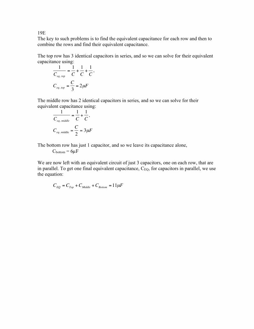
19E The key to such problems is to find the equivalent capacitance for each row and then to combine the rows and find their equivalent capacitance. The top row has 3 identical capacitors in series, and so we can solve for their equivalent capacitance using:
The middle row has 2 identical capacitors in series, and so we can solve for their equivalent capacitance using:
The bottom row has just 1 capacitor, and so we leave its capacitance alone,
Cbottom = 6µF We are now left with an equivalent circuit of just 3 capacitors, one on each row, that are in parallel. To get one final equivalent capacitance, CEQ, for capacitors in parallel, we use the equation:
€
1Ceq, top
=1C
+1C
+1C
,
Ceq, top =C3
= 2µF
€
1Ceq, middle
=1C
+1C
,
Ceq, middle =C2
= 3µF
€
CEQ = CTop +CMiddle +CBottom =11µF

20D As usual with circuits such as these, we need to simplify the circuit to determine the equivalent capacitance, CEQ. Capacitors 2 and 3 are parallel to each other and can be combined simply be adding the capacitance values together to get C23 = 15 µF. The circuit is now equivalent to two capacitors in series, capacitor 1 with capacitance 30µF, and the combined parallel capacitors with equivalent capacitance 15µF. The last step in simplifying the circuit is to determine the equivalent capacitance of the 30µF and 15µF capacitors in series, which is:
Now that we have our equivalent capacitance of 10 µF, we can use the equation below to determine total charge for this circuit: If we then return back to the simplified version of the circuit that had capacitor 1 in series with the equivalent capacitance of 15µF (from capacitors 2 and 3 in parallel), we can then see that since the capacitors are in series, the rule is that the charge going across each capacitor is the same and equal to the total charge. Thus the charge across capacitor is the same as the total charge and equal to 1200µC.
21E In order to use the equation for discharging, we should consider the amount of charge remaining after three time constants, which would have to be q(t)/q0. Also we can substitute time, t, with 3t, which is three time constants. We can also substitute RC, which is also equal to t, and we get:
This means that after three time constants, we have 4.98% left, which means that charge has been reduced by 95.02%. Note that the fact that charge had been reduced by 63% after one time constant was useless information if you solve it this way.
€
1Ceq
=130
+115,
Ceq =10µF
€
QTotal = CEQV = (10µF)(120V ) =1200µC
€
q(t)q0
= e−tRC = e
−3ττ = e−3 = 0.0498 = 4.98%

22D Using the appropriate equations for resistors in parallel, the two resistors at the top left of the circuit can be combined into equivalent resistance of 15 ohms. Also, the two resistors in series at the bottom are the equivalent of 60 ohms. Thus the circuit can be redrawn as shown velow:
At this stage the current can get from “a” to “b” by travelling through either the 15 ohm resistor or the 60 ohm resistor. It does not need to go via the 30 ohm resistor at the top right. Which means that for all intents and purposes we can ignore it. So now we really have a simple parallel circuit with resistors of 15 and 60 ohms, and an equivalent resistance of 12 ohms. 23D Looking at the currents entering and leaving any of the junctions where the wires meet gives the following equation: I2 + I3 = -I1. This can be rewritten to get answer D. 24D We treat the resistors in series on the top half of the circuit as one resistor of 12 ohms, and the resistors at the bottom as one resistor of 596 ohms. So the circuit is really a parallel circuit with equivalent resistance of 11.8 ohms. 25D The voltage drops from 9 V to 8.5 V due to the internal resistance. This 0.5 V lost within the battery can be set equal to V = IR, allowing us to solve for the current, I, to get:
I = V/R = 0.5/0.1 = 5 A

26A Remember that going across a battery from + to – makes the potential drop negative, and going against the direction of current when crossing a resistor makes the drop positive. Only answer A obeys these rules. 27D Initially, the capacitor will not affect the resistance of the circuit, and you can pretend that it is not even there. Thus the current in the circuit will be I = V/R, regardless of the capacitance, and is thus 18/2 = 9 Amps. 28D For any RC circuit, you can use the loop law to include the capacitor (assuming it has charge) so that it looks as follows:
This can be rewritten to solve for current:
29D Since the current density, J, is not uniform along the cross-section of the conductor, we must use the equation:
We must replace J with the function given in the question, and dA represents the derivative of the area of the cylinder’s cross-section, 2pr, giving us:
€
ε − Ri − qC
= 0
€
i =ε −
qC
R= 4
€
I = J • dA∫
€
I =Kr2
2R"
# $
%
& ' 2πr( )
0
R∫ dr =
KπR
r30
R∫ =
KπR4
4R=KπR3
4
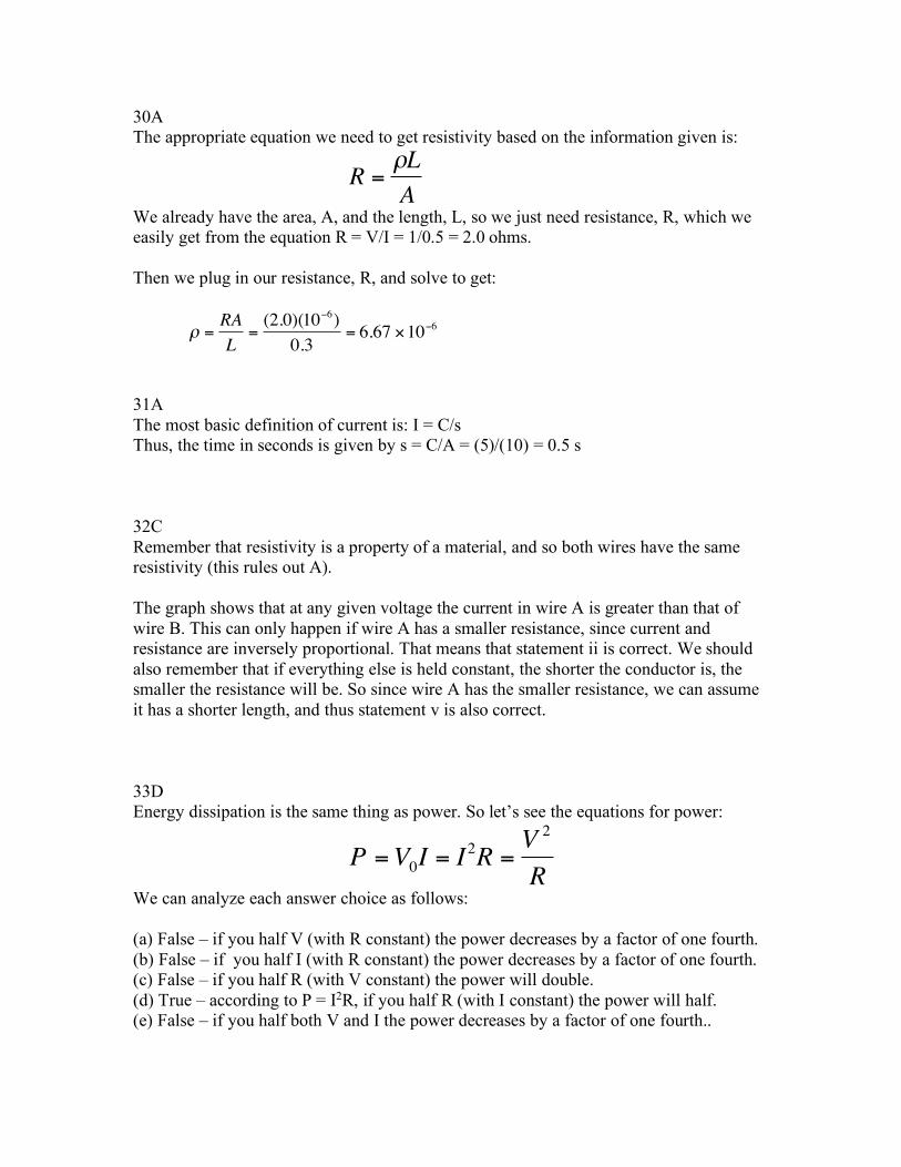
30A The appropriate equation we need to get resistivity based on the information given is:
We already have the area, A, and the length, L, so we just need resistance, R, which we easily get from the equation R = V/I = 1/0.5 = 2.0 ohms. Then we plug in our resistance, R, and solve to get:
31A The most basic definition of current is: I = C/s Thus, the time in seconds is given by s = C/A = (5)/(10) = 0.5 s 32C Remember that resistivity is a property of a material, and so both wires have the same resistivity (this rules out A). The graph shows that at any given voltage the current in wire A is greater than that of wire B. This can only happen if wire A has a smaller resistance, since current and resistance are inversely proportional. That means that statement ii is correct. We should also remember that if everything else is held constant, the shorter the conductor is, the smaller the resistance will be. So since wire A has the smaller resistance, we can assume it has a shorter length, and thus statement v is also correct. 33D Energy dissipation is the same thing as power. So let’s see the equations for power:
We can analyze each answer choice as follows: (a) False – if you half V (with R constant) the power decreases by a factor of one fourth. (b) False – if you half I (with R constant) the power decreases by a factor of one fourth. (c) False – if you half R (with V constant) the power will double. (d) True – according to P = I2R, if you half R (with I constant) the power will half. (e) False – if you half both V and I the power decreases by a factor of one fourth..
€
R =ρLA
€
ρ =RAL
=(2.0)(10−6)
0.3= 6.67 ×10⁻⁶
€
P =V0I = I2R =V 2
R

34D The Biot-Savart Law for magnetic fields from a current is used to determine the direction of the field. By pointing your thumb in the direction of the current, your fingers curl in the direction of the magnetic field. From this we determine that the two wires on the right going into the page will cancel each other out at point P (the top right wire produces a field to the left, and the bottom right wire produces an equal field to the right). The other wires both produce magnetic fields pointing right at point P. 35B The equation for any circular loop is given by:
However, since we are only dealing with half a loop, we will get half the amount of magnetic field, B/2, which equals 1.0 x 10⁻⁵ T.
36E For a charge/current moving in a circular path, the Biot-Savart Law says to point your thumb in the direction of motion and your fingers will curl in the direction of the magnetic field. Doing this with the particles causes your fingers to curl into the page at the center of the circle. However, all rules are reversed when the charge is negative, and so the field will point out of the page instead.
€
B = − µ0i
2R= 2.0 ×10⁻⁵T

37B For each wire the direction of the magnetic field can be determined by pointing your thumb along the wire and curling your fingers in the direction of the field. Since both currents are parallel (and assuming the current moves to the right), the top wire produces a field going into the page, while the bottom wire makes a field going out of the page, as shown below:
This means that at the midway point, which is 0.2 m from each wire, the fields will oppose each other, and the net magnetic field will be the difference between the two. For a straight wire carrying current, the magnetic field at a distance, R, from the wire is:
Thus the net field will be B1 – B2:
38C Remember that the capacitance is decided once the capacitor is built, and cannot be changed after that point. Thus, plate separation, plate area, and the insertion of a dielectric material, are the only factors that influence capacitance. 39B Ampere’sLawtellsusthatthelineintegralforthemagneticfieldwithintheclosedloopisgivenbyµ0Ienc, which in this instance is equal to µ0(5), as the two wires going into the page cancel out two of the three wires going out of the page, leaving only one 5A wire remaining. Since µ0 = 4p x 10-7, µ0Ienc = 20p x 10-7 = 2p x 10-6 Tm. Lastly, remember that the sign of the line integral is determined by comparing the direction of the path with the direction of the magnetic field created by the current-carrying wire. The path is clockwise, and since the current is moving out of the page, the right-hand-rule shows the magnetic field is directed counterclockwise. Thus, since the path and the magnetic field are moving in opposite directions, the line integral needs to be negative.
€
B = − µ0i
2πR
€
B 1 − B 2 = −
µ0(4)2π (0.1)
$
% &
'
( ) − −
µ0(5)2π (0.1)
$
% &
'
( ) = 2 ×10⁻⁶T

40A The RC circuit has an uncharged capacitor initially connected to a battery, thus the appropriate equation we need to use is for charging a capacitor:
Since we are looking to solve for time, t, when the charge, q(t) is 75% of its maximum value, this is equivalent to substituting q(t) with 0.75q0 to get:
Themaximumchargecancelsonbothsides,andwesimplifytoget:
The negatives cancel on each side, and we can replace 0.25 with 1/4:
Lastlywesolvefortime,t,andendupwith:
NotethatalthoughthisanswerlooksverysimilartoB,itisnotthesame,asoursolutionhasanegativesigninfrontofit.Giventhatnoneoftheanswerchoiceshavenegativesigns,wehavetotryandbecreative,andrecognizethatifwetakethereciprocalofthevaluewithinthenaturallogfunctionitflipsthesign,;meaningthatln(1/4)isequalto–ln(4).Thustheanswerendsupbeing:
q(t) = q0 (1− e− tRC )
0.75q0 = q0 (1− e− tRC )
−0.25= −e−tRC
1/ 4 = e−tRC
ln(1 / 4) = ln(e−tRC )
ln(1 / 4) = − tRC
t = −RC ln(1 / 4)
t = RC ln(4)