PHY2049 - Fall 2016 - HW7 Solutionsmajewski/2049/solns/hw7/hw7_solutions.pdf · PHY2049 - Fall 2016...
12
PHY2049 - Fall 2016 - HW7 Solutions Allen Majewski Department Of Physics, University of Florida 2001 Museum Rd. Gainesville, FL 32611 October 11, 2016 These are solutions to Halliday, Resnick, Walker Chapter 29 No: 18, 25, 30, 39, 41, 48, 55, 62 1 29.18 Figure 1: Problem 29.18 A current is set up in a wire loop consisting of a semicircle of radius 4.00 cm, a smaller concentric semicircle, and two radial straight lengths, all in the same plane. Figure 29-46a shows the arrangement but is not drawn to scale. The magnitude of the magnetic field produced at the center of curvature is 47.25 μT. The smaller semicircle is then flipped over (rotated) until the loop is again entirely in the same plane (Fig. 29-46b). The magnetic 1
Transcript of PHY2049 - Fall 2016 - HW7 Solutionsmajewski/2049/solns/hw7/hw7_solutions.pdf · PHY2049 - Fall 2016...

PHY2049 - Fall 2016 - HW7 Solutions
Allen Majewski
Department Of Physics, University of Florida2001 Museum Rd. Gainesville, FL 32611
October 11, 2016
These are solutions to Halliday, Resnick, Walker Chapter 29 No: 18, 25,30, 39, 41, 48, 55, 62
1 29.18
Figure 1: Problem 29.18
A current is set up in a wire loop consisting of a semicircleof radius 4.00 cm, a smaller concentric semicircle, and two radialstraight lengths, all in the same plane. Figure 29-46a shows thearrangement but is not drawn to scale. The magnitude of themagnetic field produced at the center of curvature is 47.25 µT.The smaller semicircle is then flipped over (rotated) until the loopis again entirely in the same plane (Fig. 29-46b). The magnetic
1
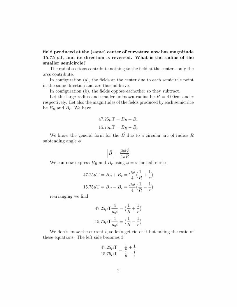
field produced at the (same) center of curvature now has magnitude15.75 µT, and its direction is reversed. What is the radius of thesmaller semicircle?
The radial sections contribute nothing to the field at the center - only thearcs contribute.
In configuration (a), the fields at the center due to each semicircle pointin the same direction and are thus additive.
In configuration (b), the fields oppose eachother so they subtract.Let the large radius and smaller unknown radius be R = 4.00cm and r
respectively. Let also the magnitudes of the fields produced by each semicirlcebe BR and Br. We have
47.25µT = BR +Br
15.75µT = BR −Br
We know the general form for the ~B due to a circular arc of radius Rsubtending angle φ ∣∣∣ ~B∣∣∣ =
µ0iφ
4πR
We can now express BR and Br using φ = π for half circles
47.25µT = BR +Br =µ0i
4
( 1
R+
1
r
)15.75µT = BR −Br =
µ0i
4
( 1
R− 1
r
)rearranging we find
47.25µT4
µ0i=( 1
R+
1
r
)15.75µT
4
µ0i=( 1
R− 1
r
)We don’t know the current i, so let’s get rid of it but taking the ratio of
these equations. The left side becomes 3:
47.25µT
15.75µT=
1R
+ 1r
1R− 1
r
2
3 =1R
+ 1r
1R− 1
r
3
R− 3
r=
1
R+
1
r
2
R=
4
r
2r = 4R
r =R
2=
4.00cm
2= 2.00cm
2 29.25
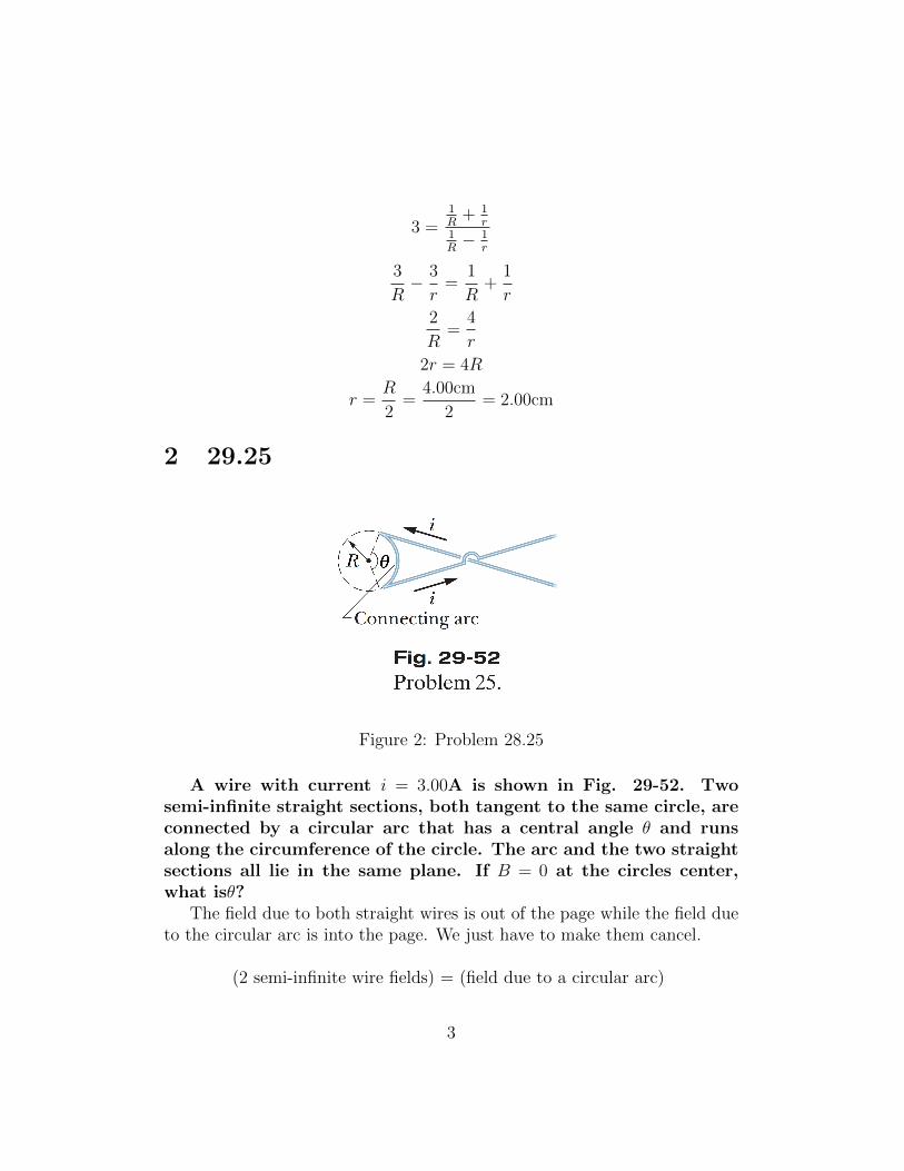
Figure 2: Problem 28.25
A wire with current i = 3.00A is shown in Fig. 29-52. Twosemi-infinite straight sections, both tangent to the same circle, areconnected by a circular arc that has a central angle θ and runsalong the circumference of the circle. The arc and the two straightsections all lie in the same plane. If B = 0 at the circles center,what isθ?
The field due to both straight wires is out of the page while the field dueto the circular arc is into the page. We just have to make them cancel.
(2 semi-infinite wire fields) = (field due to a circular arc)
3
If you forgot the field due to a semi-infinite wire, you’re not alone. Sodid I. But I know I can arrive at the expression from the precious few thingsI do know cold, such as Ampere’s law. Let’s do the work of getting thatexpression now using Ampere’s law and some symmetry.
Your book derives the field due to a semi-infinite straight wire using theBiot-Savart law. This is formal, but probably the worst way to do it by handquickly. You should avoid using Biot-Savart at all costs, in favor of Ampere’slaw, when possible.
The field due to a semi-infinite wire is half that of the infinite wire. Thatcase is easy to handle with Ampere’s law:∮
loop
~B · d~s = µ0ienc
In the case of the infinite wire, Ampere’s law delivers
Binf 2 π R = µ0i
Binf =µ0i
2πR
Now ~B for the semi-infinite case has the same direction and half themagnitude
Bsemi−inf =µ0i
4πR
This is the B we will use for the wires. Remember
2Bsemi−inf = Barc
The B due to a circular arc with radius R subtending an angle θ is still
Barc =µ0iθ
4πR
Now we just enforce 2Bsemi−inf = Barc
2µ0i
4πR=µ0iθ
4πR
2 = θ
The angle here is measured in radians. θ = 2rad = 114.592◦.
4

3 29.30
Figure 3: Problem 29.30
Two long straight thin wires with current lie against an equallylong plastic cylinder, at radius R = 20.0cm from the cylinders cen-tral axis. Figure 29-57a shows, in cross section, the cylinder andwire 1 but not wire 2. With wire 2 fixed in place, wire 1 is movedaround the cylinder, from angle θ1 = 0◦ to angle θ1 = 180◦, throughthe first and second quadrants of the xy coordinate system. Thenet magnetic field ~B at the center of the cylinder is measured as afunction of θ1. Figure 29-57b gives the x component Bx of that fieldas a function of θ1 (the vertical scale is set by Bxs = 6.0µT), andFig. 29-57c gives the y component By (the vertical scale is set byBys = 4.0µT). (a) At what angle θ2 is wire 2 located? What are the(b) size and (c) direction (into or out of the page) of the current
5
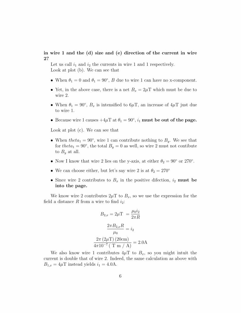
in wire 1 and the (d) size and (e) direction of the current in wire2?
Let us call i1 and i2 the currents in wire 1 and 1 respectively.Look at plot (b). We can see that
• When θ1 = 0 and θ1 = 90◦, B due to wire 1 can have no x-component.
• Yet, in the above case, there is a net Bx = 2µT which must be due towire 2.
• When θ1 = 90◦, Bx is intensified to 6µT, an increase of 4µT just dueto wire 1.
• Because wire 1 causes +4µT at θ1 = 90◦, i1 must be out of the page.
Look at plot (c). We can see that
• When theta1 = 90◦, wire 1 can contribute nothing to By. We see thatfor theta1 = 90◦, the total By = 0 as well, so wire 2 must not contibuteto By at all.
• Now I know that wire 2 lies on the y-axis, at either θ2 = 90◦ or 270◦.
• We can choose either, but let’s say wire 2 is at θ2 = 270◦
• Since wire 2 contributes to Bx in the positive difection, i2 must beinto the page.
We know wire 2 contributes 2µT to Bx, so we use the expression for thefield a distance R from a wire to find i2:
B2,x = 2µT =µ0i22πR
2πB2,xR
µ0
= i2
2π (2µT) (20cm)
4π10−7 ( T m / A)= 2.0A
We also know wire 1 contributes 4µT to Bx, so you might intuit thecurrent is double that of wire 2. Indeed, the same calculation as above withB1,x = 4µT instead yields i1 = 4.0A.
6
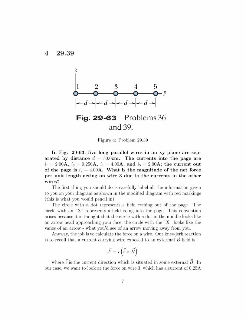
4 29.39
Figure 4: Problem 29.39
In Fig. 29-63, five long parallel wires in an xy plane are sep-arated by distance d = 50.0cm. The currents into the page arei1 = 2.00A, i3 = 0.250A, i4 = 4.00A, and i5 = 2.00A; the current outof the page is i2 = 4.00A. What is the magnitude of the net forceper unit length acting on wire 3 due to the currents in the otherwires?
The first thing you should do is carefully label all the information givento you on your diagram as shown in the modified diagram with red markings(this is what you would pencil in).
The circle with a dot represents a field coming out of the page. Thecircle with an ”X” represents a field going into the page. This conventionarises because it is thought that the circle with a dot in the middle looks likean arrow head approaching your face; the circle with the ”X” looks like thevanes of an arrow - what you’d see of an arrow moving away from you.
Anyway, the job is to calculate the force on a wire. Our knee-jerk reactionis to recall that a current carrying wire exposed to an extermal ~B field is
~F = i(~× ~B
)where ~ is the current direction which is situated in some external ~B. In
our case, we want to look at the force on wire 3, which has a current of 0.25A
7
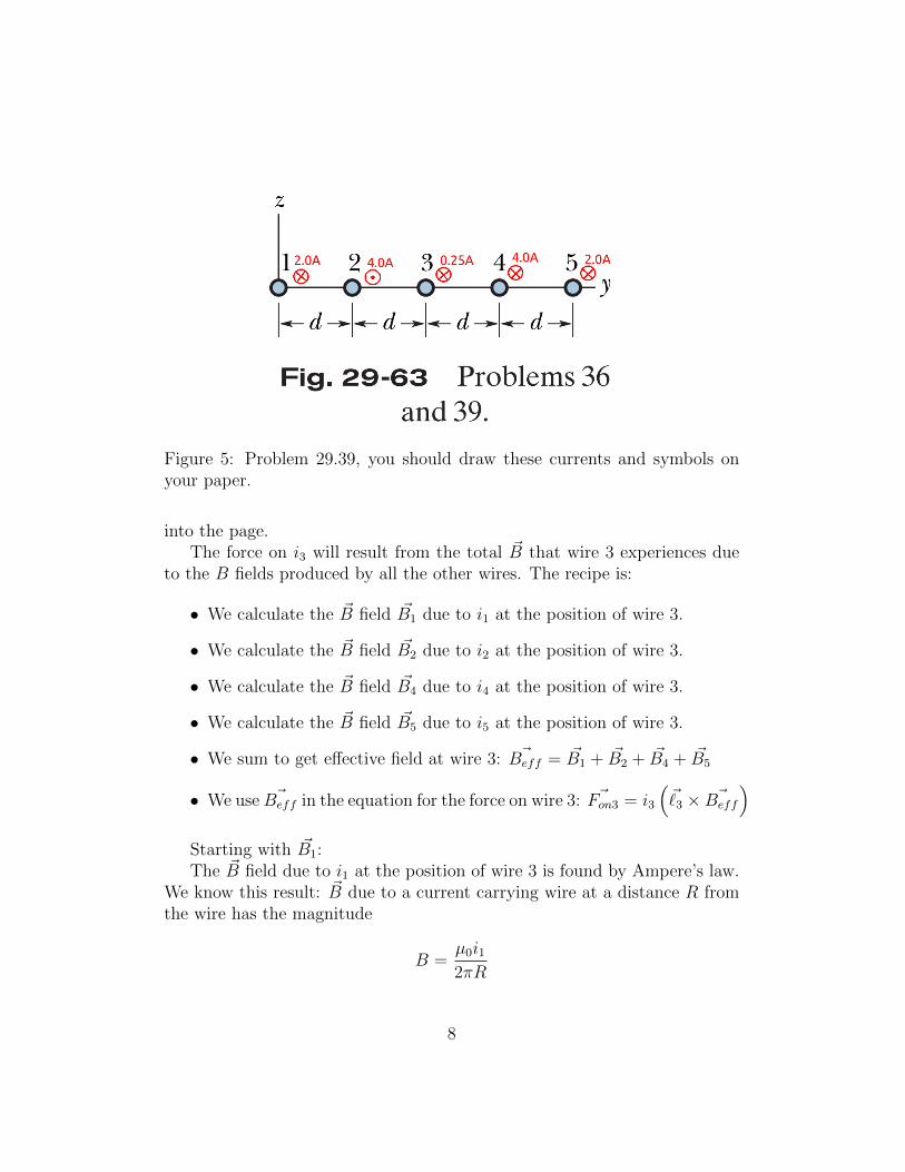
Figure 5: Problem 29.39, you should draw these currents and symbols onyour paper.
into the page.The force on i3 will result from the total ~B that wire 3 experiences due
to the B fields produced by all the other wires. The recipe is:
• We calculate the ~B field ~B1 due to i1 at the position of wire 3.
• We calculate the ~B field ~B2 due to i2 at the position of wire 3.
• We calculate the ~B field ~B4 due to i4 at the position of wire 3.
• We calculate the ~B field ~B5 due to i5 at the position of wire 3.
• We sum to get effective field at wire 3: ~Beff = ~B1 + ~B2 + ~B4 + ~B5
• We use ~Beff in the equation for the force on wire 3: ~Fon3 = i3
(~3 × ~Beff
)Starting with ~B1:The ~B field due to i1 at the position of wire 3 is found by Ampere’s law.
We know this result: ~B due to a current carrying wire at a distance R fromthe wire has the magnitude
B =µ0i12πR
8
and a direction given by the right hand rule: point your right thumb inthe direction of the current, and curl your fingers around to your palm: thefield that current produces wraps around the wire in the direction of thecurly fingers.
Anyway, getting the field due to wire 1 at the position of wire 3 requireswe use the distance R = 2d
B1 =µ0i1
2π (2d)
plugging in the numbers, and noting since i1 is into the page, ~B will pointin the −z direction (down) at wire 3:
~B1 =
(4π10−7 T m /A
)(2.0A)
4π0.5m(−z) = 4.0 10−7 T (down)
While the field due to i1 points down at wire 3, a quick examination withthe right hand rule reveals that the field from i1 points down at wire3, butthe fields due to i2, i4, and i5 all point up. So B1 will subtract and the otherswill add to the effective Beff .
Now we are ready to truly grind this out. The distances of each fromwire 3 are
d1 = 2d = 1m
d2 = d = 0.5m
d4 = d = 0.5m
d5 = 2d = 1m
The current magnitudes, again, are
i1 = 2.0A
i2 = 4.0A
i4 = 4.0A
i5 = 2.0A
So recalling only ~B1 points down, the B’s are
9
B1 = − µ0i12πd1
= −4.0e-7 T
B2 = +µ0i22πd2
= +1.6e-6 T
B4 = +µ0i42πd4
= +1.6e-6 T
B5 = +µ0i52πd5
= +4.0e-7 T
Therefore the total effective Beff at the position of wire 3 is
Beff = B1 +B2 +B3 +B4 = 3.2e-6 T up
and so the magnitude of the force on wire 3 is
Fon3 = i3 (`×Beff )
We don’t have ` which is why we are asked the force per unit length:
Fon3
`= i3Beff = 8.00 e-7 N/m
5 29.41
—-
6 29.48
—-
7 29.55
—-
8 29.62
—-
10

Figure 6: Problem 29.41
11
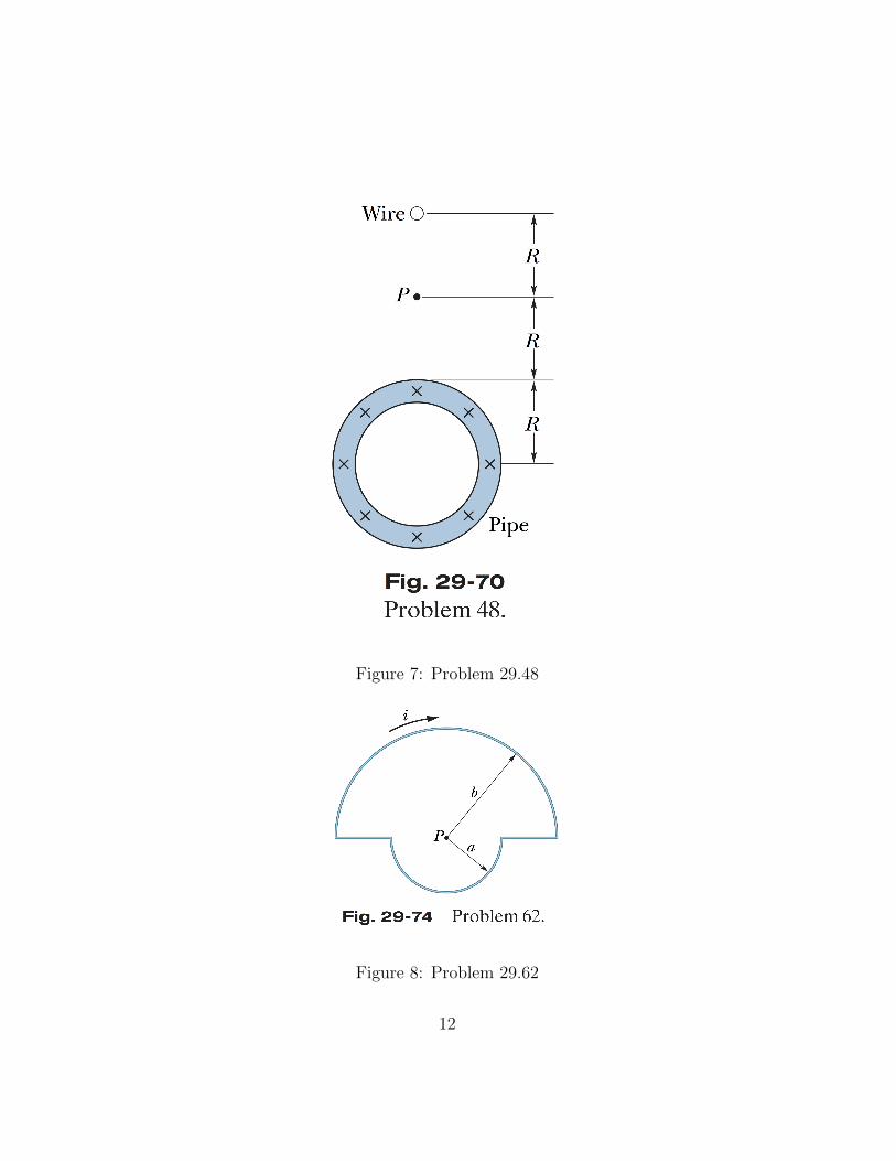
Figure 7: Problem 29.48
Figure 8: Problem 29.62
12