
Photovoltaic Energy - Ingeteam
52
Power Station Photovoltaic Energy A Complete Range of Power Stations for Grid-connected Photovoltaic Plants
Transcript of Photovoltaic Energy - Ingeteam

Power Station
Photovoltaic EnergyA Complete Range of Power Stations
for Grid-connected Photovoltaic Plants


3
Photovoltaic Energy

4
Power Station
A New Generation of Power Stations
5
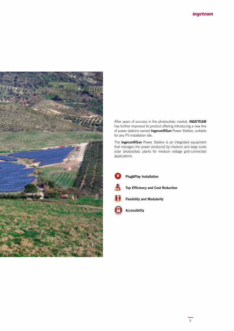
After years of success in the photovoltaic market, INGETEAM has further improved its product offering introducing a new line of power stations named Ingecon®Sun Power Station, suitable for any PV installation site.
The Ingecon®Sun Power Station is an integrated equipment that manages the power produced by medium and large scale solar photovoltaic plants for medium voltage grid-connected applications.
Plug&Play Installation
Top Effi ciency and Cost Reduction
Flexibility and Modularity
Accessibility

6
Power Station
Available in three versions:
Ingecon®Sun Power Station SHE2020ft insulated shelter
Ingecon®Sun Power Station CON2020ft insulated container
Ingecon®Sun Power Station CON4040ft insulated container
Plug&Play Installation
The Ingecon®Sun Power Station equipments are easy and rapid to install. Designed and manufactured to avoid the need of assembly operations on-site, they signifi cantly reduce the time and costs of installation. The connection to the photovoltaic inverters and to the distribution grid requires only few simple steps.
Top Effi ciency and Cost ReductionManufactured with high-quality materials, our products allow to maximize performances and reliability, as well as to optimize the costs. The INGETEAM inverters, the heart of the Ingecon®Sun Power Station, ensure industry-leading results in terms of performance and durability thanks to their modular design in both POWER MAX (multi-MPPT) and POWER MAXTER (Master/Slave) confi gurations.
MEDIUM VOLTAGE300 / 400 / 450 / 500 / 600 / 700 / 750 / 800 / 900 / 1000 / 1050 / 1150 /1200 / 1250 / 1300 / 1400 / 1500 / 1600 / 1750 / 1800 / 1850 / 2000 / 2100
INGETEAM has developed a new line of the Ingecon®Sun Power Stations with power ratings from 300 to 2.100kWp with all the necessary equipment to adapt the energy produced by the plant to the MV grid of the local distributor.
The Ingecon®Sun Power Station solutions offer top fl exibility and an easy-to-install confi guration, and can be adapted to suit the standards of any countries globally.
Comparing to the other photovoltaic solutions to be assembled on site, the Ingecon®Sun Power Stations are easy to transport, time- and cost-effi cient and offer leading results in reliability.
The Ingecon®Sun Power Stations are supplied with all the internal wiring and fully tested by Ingeteam’s highly qualifi ed technicians.
7
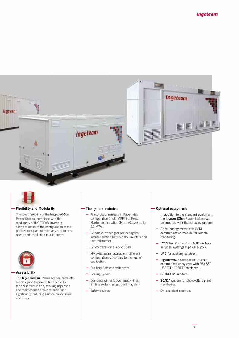
Flexibility and Modularity
The great fl exibility of the Ingecon®Sun Power Station, combined with the modularity of INGETEAM inverters, allows to optimize the confi guration of the photovoltaic plant to meet any customer’s needs and installation requirements.
The system includes
Photovoltaic inverters in Power Max confi guration (multi-MPPT) or Power Maxter confi guration (Master/Slave) up to 2.1 MWp.
LV parallel switchgear protecting the interconnection between the inverters and the transformer.
LV/MV transformer up to 36 kV.
MV switchgears, available in different confi gurations according to the type of application.
Auxiliary Services switchgear.
Cooling system.
Complete wiring (power supply lines, lighting system, plugs, earthing, etc.)
Safety devices.
Optional equipment:
In addition to the standard equipment, the Ingecon®Sun Power Station can be supplied with the following options:
Fiscal energy meter with GSM communication module for remote monitoring.
LV/LV transformer for QAUX auxiliary services switchgear power supply.
UPS for auxiliary services.
Ingecon®Sun ComBox centralized communication system with RS485/USB/ETHERNET interfaces.
GSM/GPRS modem.
SCADA system for photovoltaic plant monitoring.
On-site plant start-up.
Top Effi ciency and Cost Reduction AccessibilityThe Ingecon®Sun Power Station products are designed to provide full access to the equipment inside, making inspection and maintenance activities easier and signifi cantly reducing service down times and costs.
8
80
92
86
98
82
94
88
100
84
96
90
0 63 188125 313250 438375 500 563 625
Power StationVdc=550-625 V
Power Station
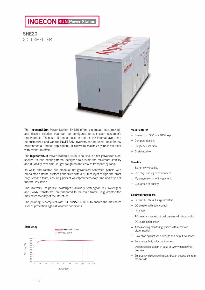
SHE2020 ft SHELTER
The Ingecon®Sun Power Station SHE20 offers a compact, customizable and fl exible solution that can be confi gured to suit each customer’s requirements. Thanks to its panel-based structure, the internal layout can be customized and various INGETEAM inverters can be used. Ideal for low environmental impact applications, it allows to maximize your investment with minimum effort.
The Ingecon®Sun Power Station SHE20 is housed in a hot-galvanized steel shelter. Its load-bearing frame, designed to provide the maximum stability and durability over time, is light-weighted and easy to transport by road.
Its walls and rooftop are made of hot-galvanized sandwich panels with prepainted external surfaces and fi lled with a 50 mm layer of rigid fi re-proof polyurethane foam, ensuring perfect waterproofness over time and effi cient thermal insulation.
The inverters, LV parallel switchgear, auxiliary switchgear, MV switchgear and LV/MV transformer are anchored to the main frame, to guarantee the maximum stability of the structure.
The painting is compliant with ISO 9227-06 NSS to ensure the maximum level of protection against weather conditions.
Main Features
Power from 300 to 2.100 kWp.
Compact design.
Plug&Play solution.
Customizable.
Benefi ts
Extremely versatile.
Industry-leading performances.
Maximum return of investment.
Guarantee of quality.
Electrical Protections
DC and AC Class II surge arresters.
DC breaker with door control.
DC fuses.
AC thermal magnetic circuit breaker with door control.
DC insulation monitor.
Anti-islanding monitoring system with automatic disconnection.
Protection against short-circuits and output overloads.
Emergency button for the inverters.
Disconnection system in case of LV/MV transformer overheat.
Emergency disconnecting pushbutton accessible from the outside.
Power (kW)
Effi c
ienc
y (%
)
Effi ciency

9
Dimensions(mm)
Dimensions
SHE20 version
Body dimensions [mm] LxDxH 6074 2424 2896
Overall dimensions [mm] 9364 6831 2896
Foundation dimensions [mm] 8000 5000 300
The structure is designed to provide full access to the equipment, making inspection, maintenance and repair activities easier on the Ingecon®Sun Power Station SHE20.
Complete accessibility is offered on the four sides, thanks to the doors equip-ped with security locks. Moreover, the transformer compartment door is equipped with an AREL safety lock with interlocking system.
The internal temperature is controlled by a high-effi ciency ventilation system with centrifugal fans. A number of internal and external probes ensure a constant ambient temperature.
The intake air is fi ltered through special grids located on the bottom side of the walls in order to provide a uniform cooling of the internal equipment.
Optional equipment
In addition to the standard equipment, the Ingecon®Sun Power Station SHE20 can be supplied with the following options:
Fiscal energy meter with GSM communication module for remote monitoring.
LV/LV transformer for auxiliary services switchgear power supply.
UPS for auxiliary services.
Ingecon®Sun ComBox centralized communication system with RS485/USB/ETHERNET interfaces.
GSM/GPRS modem
SCADA system for photovoltaic plant monitoring.
On-site plant start-up.
Internal view

10
Power Station
SHE20Physical, Electrical and Environmental characteristics
Number of power modules 2 3 4 5 6 7 8
Cooling
Cooling System Forced air cooling by thermally-controlled centrifugal fans (power supply: 400 V three phase with neutral)
Inverter compartment
Air flow 6000 m3/h 6000 m3/h 6000 m3/h 12000 m3/h 12000 m3/h 12000 m3/h 12000 m3/h
Power consumption(1) 1950 W 2770 W 3180 W 4720 W 5540 W 5950 W 6360 W
Transformer compartment
Air flow 6000 m3/h 6000 m3/h 6000 m3/h 6000 m3/h 6000 m3/h 6000 m3/h 6000 m3/h
Power consumption 720 W 720 W 720 W 720 W 720 W 720 W 720 W
Extraction grids Anti-rain model
Intake air grids (ventilated version) 8 8 8 12 12 12 12
General Information
Operating Temperature Range (2) from -20°C to +55°C
Relative Humidity 0 - 95 %
Installation Altitude (3) 1000 m above sea level
Certifications Calculation report
Safety and EMC standards EN 50178, EN 61000-6-2, EN 61000-6-4, EN 61000-3-11, EN 61000-3-12, FCC part 15
Grid Standards BDEW MT, RD 661/2007, P.O.12.3, CEI 11-20, CEI 11-20 V1, CEI 0-16, Annexes A68 e A70 TERNA, CEI 0-21, IEEE1547, Arrêté 23-04-08
Equipment
Inverter versions M series (Multi MPPT) or X series (Master/Slave)
BT POWER LV switchgear BASE version (FULL version optional)
BT-AUX switchgear BASE version (FULL version optional)
LV/MV transformer Dry type cast resin
MV switchgear Protection cells 1P or 1P-2L
Internal lighting 2 x 36 W fluorescent lamps
Emergency lighting 1 x 36 W fluorescent lamps
Auxiliary power outlet 1 x 220 V
Safety interlocks AREL security lock for LV/MV transformer compartment door
Fire safety kit 5 Kg CO2 fire extinguisher
MV safety kit Class 3 insulated gloves and 30 kV insulated footboard
Safety kit First aid kit and signals
Support system Directly on raft foundation (8 30x30 cm brackets optional)
Mechanical Details
Structure material Steel
Insulation Sandwich panels containing a 50 mm rigid fire-proof polyurethane foam filling
Notes:(1) Consumption inverter ventilation system included. (2) Ventilated version: rated output power indicated in the Technical Characteristics tables is guaranteed up to 40 °C operating temperature. Derating above 40°C of 1.8% for each °C of increase until 50 °C operating temperature.(3) For higher altitudes, please contact Ingeteam.

11
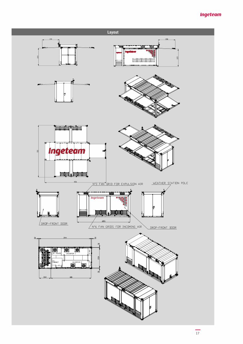
Layout

12
Foundation
Manholes Layout
Plan View
Front View
Side View

13
String Control
ComBox
Manager
INGERAS PV
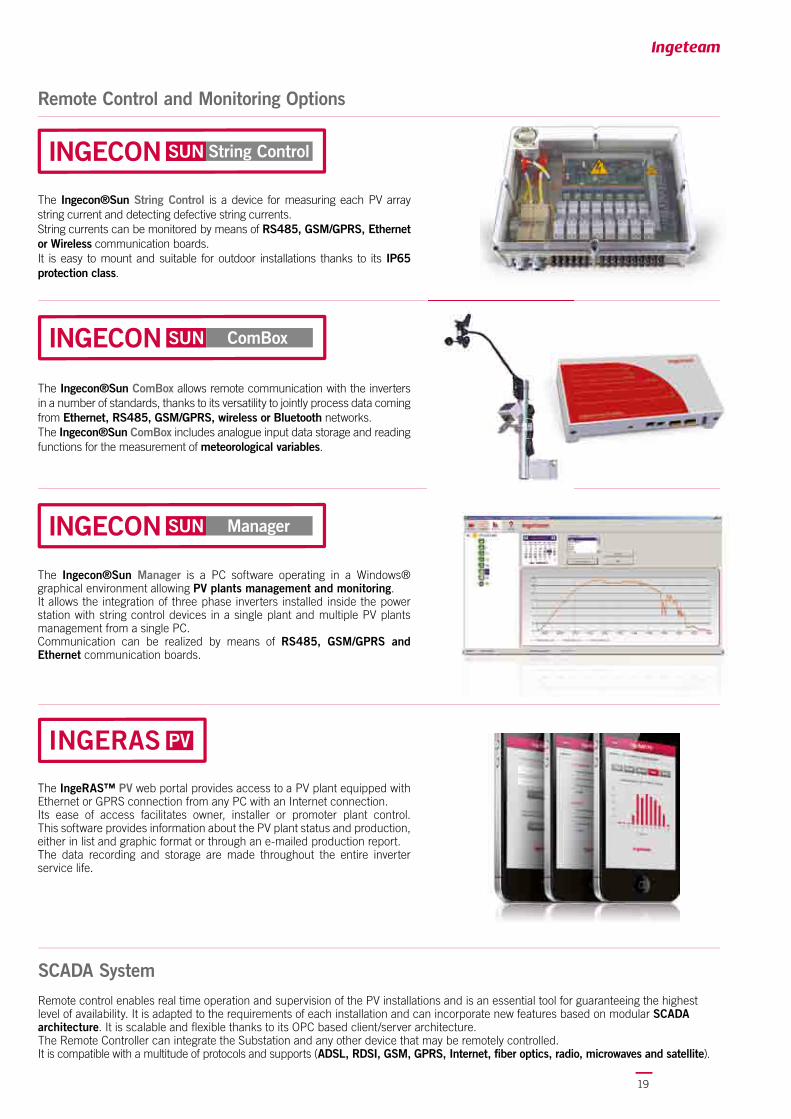
Remote control enables real time operation and supervision of the PV installations and is an essential tool for guaranteeing the highest level of availability. It is adapted to the requirements of each installation and can incorporate new features based on modular SCADA architecture. It is scalable and fl exible thanks to its OPC based client/server architecture. The Remote Controller can integrate the Substation and any other device that may be remotely controlled.It is compatible with a multitude of protocols and supports (ADSL, RDSI, GSM, GPRS, Internet, fi ber optics, radio, microwaves and satellite).
The Ingecon®Sun String Control is a device for measuring each PV array string current and detecting defective string currents.String currents can be monitored by means of RS485, GSM/GPRS, Ethernet or Wireless communication boards.It is easy to mount and suitable for outdoor installations thanks to its IP65 protection class.
The Ingecon®Sun ComBox allows remote communication with the inverters in a number of standards, thanks to its versatility to jointly process data coming from Ethernet, RS485, GSM/GPRS, wireless or Bluetooth networks.The Ingecon®Sun ComBox includes analogue input data storage and reading functions for the measurement of meteorological variables.
The Ingecon®Sun Manager is a PC software operating in a Windows® graphical environment allowing PV plants management and monitoring.It allows the integration of three phase inverters installed inside the power station with string control devices in a single plant and multiple PV plants management from a single PC.Communication can be realized by means of RS485, GSM/GPRS and Ethernet communication boards.
SCADA System
The IngeRAS™ PV web portal provides access to a PV plant equipped with Ethernet or GPRS connection from any PC with an Internet connection.Its ease of access facilitates owner, installer or promoter plant control. This software provides information about the PV plant status and production, either in list and graphic format or through an e-mailed production report.The data recording and storage are made throughout the entire inverter service life.
Remote Control and Monitoring Options

14
80
92
86
98
82
94
88
100
84
96
90
0 63 188125 313250 438375 500 563 625
Power StationVdc=550-625 V
Power Station
Main Features
Power from 300 to 2.100 kWp.
Compact design.
Plug&Play solution.
RINA approval.
Benefi ts
High versatility.
Industry-leading performances.
Maximum return of investment.
Guarantee of quality.
CON2020 ft CONTAINER
The Ingecon®Sun Power Station CON20 offers a standard solution designed to be marketed worldwide. Thanks to its RINA approval, the Ingecon®Sun Power Station CON20 can be shipped by sea everywhere in the world.
It is the ideal solution for those operators working in less accessible areas, who wish to propose a simple, easy, rapid to install and reliable solution. The Ingecon®Sun Power Station CON20 is housed in a steel body. Its single-block load-bearing frame is made of welded steel to ensure top resistance and durability over time.
Its rooftop is made of folded roofi ng sheet, coated on the inside with insulated panels. The walls are made of galvanized painted steel sandwich panels fi lled with a 50 mm layer of rigid fi re-proof polyurethane foam, ensuring perfect waterproofness over time and effi cient thermal insulation.
The inverters, LV parallel switchgear, auxiliary switchgear, MV switchgear and LV/MV transformer are anchored to the main frame, to guarantee the maximum stability of the structure.
To ensure the maximum protection against weather conditions, all the external components of the Ingecon®Sun Power Station CON20 are coated with a galvanized layer and painted with polyurethane lacquer.
Electrical Protections
DC and AC Class II surge arresters.
DC load circuit breaker with door control.
DC fuses.
AC thermal magnetic breaker with door control.
DC insulation monitor.
Anti-islanding monitoring system with automatic disconnection.
Protection against short-circuits and output overloads.
Emergency pushbutton for the inverters.
Disconnection system in case of LV/MV transformer overheating.
Emergency disconnecting pushbutton accessible from the outside.
Power (kW)
Effi c
ienc
y (%
)
Effi ciency

15
Dimensions(mm)
Dimensions
CON20 version
Body dimensions [mm] LxDxH 6074 2424 2896
Overall dimensions [mm] 9364 6831 2896
Foundation dimensions [mm] 8000 5000 300
The structure is designed to provide full access to the equipment, making inspec-tion, maintenance and repair activities easier on the Ingecon®Sun Power Station CON20.
Complete accessibility is offered on the four sides, thanks to the doors equipped with security locks. Moreover, the transformer compartment door is equipped with an AREL safety lock with interlocking system.
The internal temperature is controlled by a high-effi ciency ventilation system with centrifugal fans. A number of internal and external probes ensure a constant ambient temperature.
The intake air is fi ltered through special grids located on the bottom side of the walls in order to provide a uniform cooling of the internal equipment.
Optional equipment
In addition to the standard equipment, the Ingecon®Sun Power Station CON20 can be supplied with the following options:
Fiscal energy meter with GSM communication module for remote monitoring.
LV/LV transformer for auxiliary services switchgear power supply.
UPS for auxiliary services.
Ingecon®Sun ComBox centralized communication system with RS485/USB/ETHERNET interfaces.
GSM/GPRS modem
SCADA system for photovoltaic plant monitoring.
On-site plant start-up.
Internal view

16
Power Station
CON20Physical, Electrical and Environmental characteristics
Number of power modules 2 3 4 5 6 7 8
Cooling
Cooling System Forced air cooling by thermally-controlled centrifugal fans (power supply: 400 V three phase with neutral)
Inverter compartment
Air flow 6000 m3/h 6000 m3/h 6000 m3/h 12000 m3/h 12000 m3/h 12000 m3/h 12000 m3/h
Power consumption(1) 1950 W 2770 W 3180 W 4720 W 5540 W 5950 W 6360 W
Transformer compartment
Air flow 6000 m3/h 6000 m3/h 6000 m3/h 6000 m3/h 6000 m3/h 6000 m3/h 6000 m3/h
Power consumption 720 W 720 W 720 W 720 W 720 W 720 W 720 W
Extraction grids Anti-rain model
Intake air grids 7 7 7 12 12 12 12
General Information
Operating Temperature Range (2) from -20°C to +55°C
Relative Humidity 0 - 95 %
Installation Altitude (3) 1000 m above sea level
Certifications Calculation report
Safety and EMC standards EN 50178, EN 61000-6-2, EN 61000-6-4, EN 61000-3-11, EN 61000-3-12, FCC part 15
Grid Standards BDEW MT, RD 661/2007, P.O.12.3, CEI 11-20, CEI 11-20 V1, CEI 0-16, Annexes A68 e A70 TERNA, CEI 0-21, IEEE1547, Arrêté 23-04-08
Equipment
Inverter versions M series (Multi MPPT) or X series (Master/Slave)
BT POWER LV switchgear BASE version (FULL version optional)
BT-AUX switchgear BASE version (FULL version optional)
LV/MV transformer Dry type cast resin
MV switchgear Protection cells 1P or 1P-2L
Internal lighting 2 x 36 W fluorescent lamps
Emergency lighting 1 x 36 W fluorescent lamps
Auxiliary power outlet 1 x 220 V
Safety interlocks AREL security lock for LV/MV transformer compartment door
Fire safety kit 5 Kg CO2 fire extinguisher
MV safety kit Class 3 insulated gloves and 30 kV insulated footboard
Safety kit First aid kit and signals
Support system Directly on raft foundation (8 30x30 cm brackets optional)
Mechanical Details
Structure material Steel
Insulation Sandwich panels containing a 50 mm rigid fire-proof polyurethane foam filling
Notes:(1) Consumption inverter ventilation system included. (2) Ventilated version: rated output power indicated in the Technical Characteristics tables is guaranteed up to 40 °C operating temperature. Derating above 40°C of 1.8% for each °C of increase until 50 °C operating temperature.(3) For higher altitudes, please contact Ingeteam.
17
Layout

18
Foundation
Manholes Layout
Plan View
Side View
19
ComBox
Manager
INGERAS PV
String Control
The Ingecon®Sun String Control is a device for measuring each PV array string current and detecting defective string currents.String currents can be monitored by means of RS485, GSM/GPRS, Ethernet or Wireless communication boards.It is easy to mount and suitable for outdoor installations thanks to its IP65 protection class.
The Ingecon®Sun ComBox allows remote communication with the inverters in a number of standards, thanks to its versatility to jointly process data coming from Ethernet, RS485, GSM/GPRS, wireless or Bluetooth networks.The Ingecon®Sun ComBox includes analogue input data storage and reading functions for the measurement of meteorological variables.
The Ingecon®Sun Manager is a PC software operating in a Windows® graphical environment allowing PV plants management and monitoring.It allows the integration of three phase inverters installed inside the power station with string control devices in a single plant and multiple PV plants management from a single PC.Communication can be realized by means of RS485, GSM/GPRS and Ethernet communication boards.
Remote Control and Monitoring Options
Remote control enables real time operation and supervision of the PV installations and is an essential tool for guaranteeing the highest level of availability. It is adapted to the requirements of each installation and can incorporate new features based on modular SCADA architecture. It is scalable and fl exible thanks to its OPC based client/server architecture. The Remote Controller can integrate the Substation and any other device that may be remotely controlled.It is compatible with a multitude of protocols and supports (ADSL, RDSI, GSM, GPRS, Internet, fi ber optics, radio, microwaves and satellite).
SCADA System
The IngeRAS™ PV web portal provides access to a PV plant equipped with Ethernet or GPRS connection from any PC with an Internet connection.Its ease of access facilitates owner, installer or promoter plant control. This software provides information about the PV plant status and production, either in list and graphic format or through an e-mailed production report.The data recording and storage are made throughout the entire inverter service life.
20
80
92
86
98
82
94
88
100
84
96
90
0 63 188125 313250 438375 500 563 625
Power StationVdc=550-625 V
Power Station
Power (kW)
Effi c
ienc
y (%
)
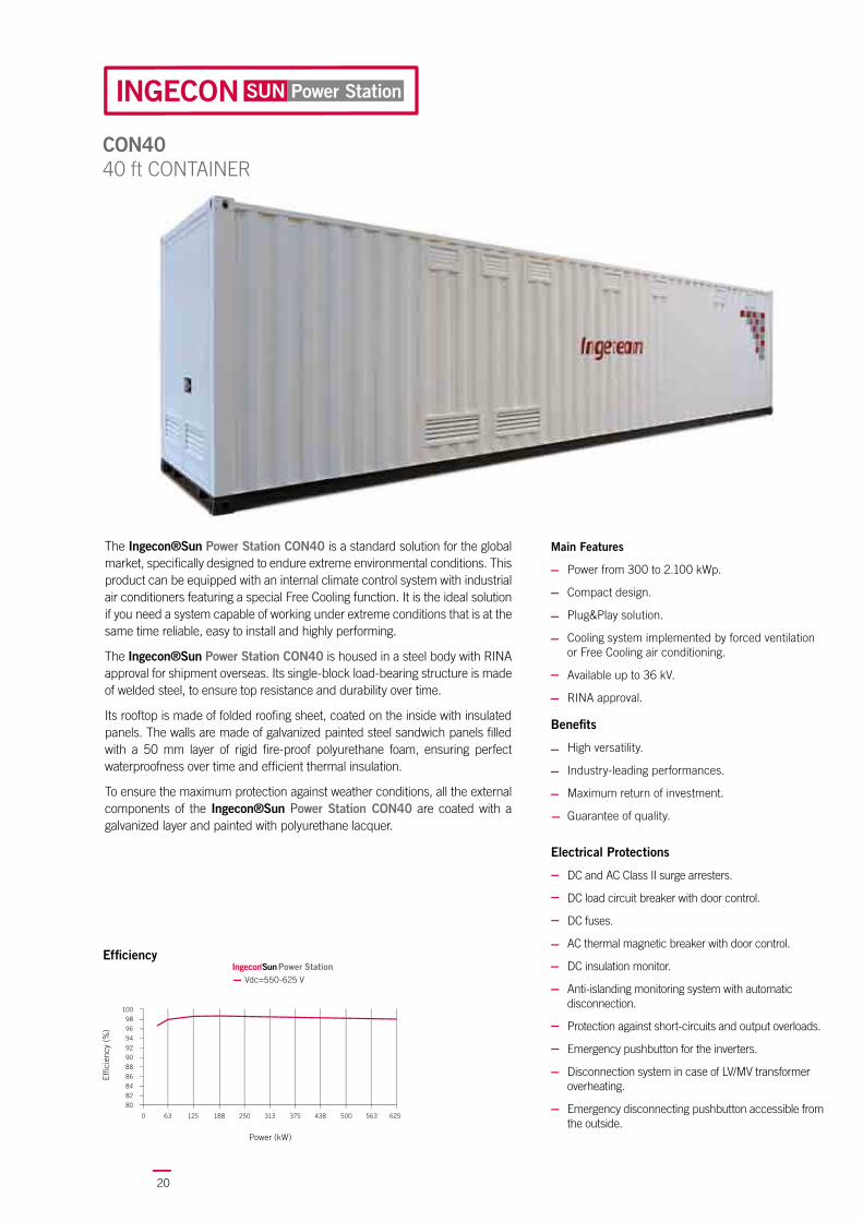
The Ingecon®Sun Power Station CON40 is a standard solution for the global market, specifi cally designed to endure extreme environmental conditions. This product can be equipped with an internal climate control system with industrial air conditioners featuring a special Free Cooling function. It is the ideal solution if you need a system capable of working under extreme conditions that is at the same time reliable, easy to install and highly performing.
The Ingecon®Sun Power Station CON40 is housed in a steel body with RINA approval for shipment overseas. Its single-block load-bearing structure is made of welded steel, to ensure top resistance and durability over time.
Its rooftop is made of folded roofi ng sheet, coated on the inside with insulated panels. The walls are made of galvanized painted steel sandwich panels fi lled with a 50 mm layer of rigid fi re-proof polyurethane foam, ensuring perfect waterproofness over time and effi cient thermal insulation.
To ensure the maximum protection against weather conditions, all the external components of the Ingecon®Sun Power Station CON40 are coated with a galvanized layer and painted with polyurethane lacquer.
Main Features
Power from 300 to 2.100 kWp.
Compact design.
Plug&Play solution.
Cooling system implemented by forced ventilation or Free Cooling air conditioning.
Available up to 36 kV.
RINA approval.
Benefi ts
High versatility.
Industry-leading performances.
Maximum return of investment.
Guarantee of quality.
Effi ciency
Electrical Protections
DC and AC Class II surge arresters.
DC load circuit breaker with door control.
DC fuses.
AC thermal magnetic breaker with door control.
DC insulation monitor.
Anti-islanding monitoring system with automatic disconnection.
Protection against short-circuits and output overloads.
Emergency pushbutton for the inverters.
Disconnection system in case of LV/MV transformer overheating.
Emergency disconnecting pushbutton accessible from the outside.
CON4040 ft CONTAINER

21
Optional equipment
In addition to the standard equipment, the Ingecon®Sun Power Station CON40 can be supplied with the following options:
Fiscal energy meter with GSM communication module for remote monitoring.
LV/LV transformer for auxiliary services switchgear power supply.
UPS for auxiliary services.
Ingecon®Sun ComBox centralized communication system with RS485/USB/ETHERNET interfaces.
GSM/GPRS modem
SCADA system for photovoltaic plant monitoring.
On-site plant start-up.
Internal view
Dimensions(mm)
Dimensions
Version CON40
Body dimensions [mm] LxDxH 12192 2438 2896
Overall dimensions [mm] 14357 3578 2896
Foundation dimensions [mm] 14000 5000 300
The structure is designed to provide full access to the equipment, making inspection, maintenance and repair activities easier on the Ingecon®Sun Power Station CON40.
The internal temperature is controlled by a high-effi ciency ventilation system with centrifugal fans. A number of internal and external probes ensure a constant ambient temperature.
An internal air condition system is available upon request, featuring Free Cooling function with an air conditioner specifi cally sized for each inverter and equipped with:
Pure Free Cooling Function: The external ambient temperature is low and the air conditioner works as a ventilation system exchanging the air with the outside and keeping the compressor turned off.
Assisted Free Cooling Function: The external ambient temperature is relatively low so as to allow the operation of the Free Cooling function, but not suffi cient to maintain the internal temperature at the desired level. Therefore, the compressor is operated partially.
Cooling Function: The compressor is active and the system operates as a normal air conditioning system.

22
Power Station
CON40Physical, Electrical and Environmental characteristics
Number of power modules 2 3 4 5 6 7 8
Cooling
Cooling System Forced air cooling by thermally-controlled centrifugal fans (power supply: 400 V three phase with neutral)
Air conditioning system (optional)
Inverter compartment, ventilated version
FanAir flow 6000 m3/h 6000 m3/h 6000 m3/h 12000 m3/h 12000 m3/h 12000 m3/h 12000 m3/h
Power consumption(1) 1950 W 2770 W 3180 W 4720 W 5540 W 5950 W 6360 W
Inverter compartment, free cooling conditioned version
Free cooling (Fan)
Air flow 3800 m3/h 3800 m3/h 3800 m3/h 7600 m3/h 7600 m3/h 7600 m3/h 7600 m3/h
Power consumption(1) 3030 W 3850 W 4260 W 6880 W 7700 W 8110 W 8520 W
Cooling function
Cooling capacity
17,8 kW 17,8 kW 17,8 kW 35,6 kW 35,6 kW 35,6 kW 35,6 kW
Power consumption(1) 10330 W 11150 W 11560 W 21480 W 22300 W 22710 W 23120 W
Transformer compartment
Air flow 9000 m3/h 9000 m3/h 9000 m3/h 9000 m3/h 9000 m3/h 9000 m3/h 9000 m3/h
Power consumption
1080 W 1080 W 1080 W 1080 W 1080 W 1080 W 1080 W
Extraction grids Anti-rain model
Intake air grids (ventilated version) 11 11 11 11 11 11 11
Intake air grids (conditioned version) 8 8 8 9 9 9 9
General Information
Operating Temperature Range (2) from -20°C to +55°C
Relative Humidity 0 - 95 %
Installation Altitude (3) 1000 m above sea level
Certifications Calculation report
Safety and EMC standards EN 50178, EN 61000-6-2, EN 61000-6-4, EN 61000-3-11, EN 61000-3-12, FCC part 15
Grid Standards BDEW MT, RD 661/2007, P.O.12.3, CEI 11-20, CEI 11-20 V1, CEI 0-16, Annexes A68 e A70 TERNA, CEI 0-21, IEEE1547, Arrêté 23-04-08
Equipment
Inverter versions M series (Multi MPPT) or X series (Master/Slave)
BT POWER LV switchgear BASE version (FULL version optional)
BT-AUX switchgear BASE version (FULL version optional)
LV/MV transformer Dry type cast resin
MV switchgear Protection cells 1P or 1P-2L
Internal lighting 2 x 36 W fluorescent lamps
Emergency lighting 1 x 36 W fluorescent lamps
Auxiliary power outlet 1 x 220 V
Safety interlocks AREL security lock for LV/MV transformer compartment door
Fire safety kit 5 Kg CO2 fire extinguisher
MV safety kit Class 3 insulated gloves and 30 kV insulated footboard
Safety kit First aid kit and signals
Support system Directly on raft foundation
Mechanical Details
Structure material Steel
Insulation Sandwich panels containing a 50 mm rigid fire-proof polyurethane foam filling
Notes:(1) Consumption inverter ventilation system included. (2) Ventilated version: rated output power indicated in the Technical Characteristics tables is guaranteed up to 40 °C operating temperature. Derating above 40°C of 1.8% for each °C of increase until 50 °C operating temperature. Conditioned version: rated output power indicated in the Technical Characteristics tables is guaranteed up to 50 °C operating temperature. Derating above 50°C of 1.8% for each °C of increase until 55 °C operating temperature(3) For higher altitudes, please contact Ingeteam.

23
Layout

24
Foundation
Manhole Layout
Plan View
Left Side View
Front View

25
ComBox
Manager
INGERAS PV
String Control
The Ingecon®Sun String Control is a device for measuring each PV array string current and detecting defective string currents.String currents can be monitored by means of RS485, GSM/GPRS, Ethernet or Wireless communication boards.It is easy to mount and suitable for outdoor installations thanks to its IP65 protection class.
The Ingecon®Sun ComBox allows remote communication with the inverters in a number of standards, thanks to its versatility to jointly process data coming from Ethernet, RS485, GSM/GPRS, wireless or Bluetooth networks.The Ingecon®Sun ComBox includes analogue input data storage and reading functions for the measurement of meteorological variables.
The Ingecon®Sun Manager is a PC software operating in a Windows® graphical environment allowing PV plants management and monitoring.It allows the integration of three phase inverters installed inside the power station with string control devices in a single plant and multiple PV plants management from a single PC.Communication can be realized by means of RS485, GSM/GPRS and Ethernet communication boards.
Remote Control and Monitoring Options
Remote control enables real time operation and supervision of the PV installations and is an essential tool for guaranteeing the highest level of availability. It is adapted to the requirements of each installation and can incorporate new features based on modular SCADA architecture. It is scalable and fl exible thanks to its OPC based client/server architecture. The Remote Controller can integrate the Substation and any other device that may be remotely controlled.It is compatible with a multitude of protocols and supports (ADSL, RDSI, GSM, GPRS, Internet, fi ber optics, radio, microwaves and satellite).
SCADA System
The IngeRAS™ PV web portal provides access to a PV plant equipped with Ethernet or GPRS connection from any PC with an Internet connection.Its ease of access facilitates owner, installer or promoter plant control. This software provides information about the PV plant status and production, either in list and graphic format or through an e-mailed production report.The data recording and storage are made throughout the entire inverter service life.

26
Power Station
M220 INVERTER SERIESMULTI-MPPT CONFIGURATION
Model 300 450 600 750 900 1050 1200
Ingecon®Sun Power Max 250 M220 Indoor 375 M220 Indoor 500 M220 Indoor250 M220 Indoor
+ 375 M220 Indoor375 M220 Indoor
+ 375 M220 Indoor375 M220 Indoor
+ 500 M220 Indoor500 M220 Indoor
+ 500 M220 Indoor
Input (DC)
Recommended PV Array Power Range (1) 283 - 325 kWp 424 - 488 kWp 566 - 650 kWp 707 - 813 kWp 848 - 976 kWp 990 - 1138 kWp 1132 - 1300 kWp
MPPT Voltage Range 405 - 820 V
Max DC Voltage (2) 920 V
Max DC Current 800 A 1200 A 1600 A 2000 A 2400 A 2800 A 3200 A
DC Inputs 8 12 16 20 24 28 32
DC Connection Type From below by means of telescopic trapdoors, connection on bars through D40 cable glands (max cable diameter 40 mm)
Number of Power Modules 2 3 4 5 6 7 8
Number of MPPT 2 3 4 5 6 7 8
Input Protections (Inverter)
Overvoltage protection DC Class II surge arresters with removable cartridge
DC switch DC load circuit breaker with door control (for each independent module)
Other protections DC fuses, DC contactor for PV array disconnection (for each independent module), DC insulation monitor, emergency pushbutton
Output (AC)
Rated AC Power (3) 275 kW 412.5 kW 550 kW 687.5 kW 825 kW 962.5 kW 1100 kW
Max AC Current (Low Voltage) 736 A 1104 A 1472 A 1840 A 2208 A 2576 A 2944 A
Rated AC Voltage 3 x 10 ... 36 kV IT
AC Frequency 50 / 60 Hz
Cos Phi (4) 1
Adjustable Cos Phi ± 0.9 a Pnom
THD (Total Harmonic Distortion) (4) < 3%
AC Connection Type From below by means of telescopic trapdoor
Output Protections (Inverter)
Overvoltage protection AC Class II surge arresters with removable cartridge
AC switch AC thermal magnetic breaker (for each independent module, not available in NAC models)
Anti-islanding protection Yes, with automatic disconnection
Other protections AC output short-circuit and overvoltage protections
Operating Performance (Inverter)
Max Efficiency 98.1 % 98.1 % 98.1 % 98.1 % 98.1 % 98.1 % 98.1 %
European Efficiency / CEC Efficiency 97.7 % / 97.3 % 97.7 % / 97.3 % 97.7 % / 97.3 % 97.7 % / 97.3 % 97.7 % / 97.3 % 97.7 % / 97.3 % 97.7 % / 97.3 %
Power Consumption in Stand-by Mode (5) 60 W 90 W 120 W 150 W 180 W 210 W 240 W
Night-time Consumption < 5 W < 5 W < 5 W < 10 W < 10 W < 10 W < 10 W
Total Weight
SHE20 5,55 t 6,12 t 6,95 t 8,35 t 8,55 t 9,15 t 10,25 t
CON20 6,25 t 6,82 t 7,65 t 9,05 t 9,25 t 9,85 t 10,95 t
CON20 RINA 6,85 t 7,42 t 8,25 t 9,65 t 9,85 t 10,45 t 11,55 t
CON40 Ventilated RINA 9,75 t 10,32 t 11,15 t 12,55 t 12,75 t 13,35 t 14,45 t
CON40 Conditioned RINA 10,00 t 10,57 t 11,40 t 13,05 t 13,25 t 13,85 t 14,95 t
Notes: (1) Depending on the type of installation and geographical location.(2) 1000 Vdc optional. Never to be exceeded. Consider the voltage increase of the ‘VOC’ no-load voltage at low temperatures.(3) The rated AC power is guaranteed at the ambient temperature pointed at page 10, 16 and 22.(4) For Pout > 25% of the rated power and voltage according to IEC 61000-3-4.(5) Power consumption from PV array (not including LV/MV transformer no-load losses).
Technical Characteristics

27
Power Station
M275 INVERTER SERIESMULTI-MPPT CONFIGURATION
Technical Characteristics
Model 400 600 800 1000 1200 1400 1600
Ingecon®Sun Power Max 315 M275 Indoor 500 M275 Indoor 630 M275 Indoor315 M275 Indoor
+ 500 M275 Indoor500 M275 Indoor
+ 500 M275 Indoor500 M275 Indoor
+ 630 M275 Indoor630 M275 Indoor
+ 630 M275 Indoor
Input (DC)
Recommended PV Array Power Range (1) 345 - 410 kWp 531 - 650 kWp 709 - 819 kWp 885 - 1060 kWp 1062 - 1300 kWp 1240 - 1469 kWp 1418 - 1638 kWp
MPPT Voltage Range 445 - 820 V
Max DC Voltage (2) 920 V
Max DC Current 800 A 1200 A 1600 A 2000 A 2400 A 2800 A 3200 A
DC Inputs 8 12 16 20 24 28 32
DC Connection Type From below by means of telescopic trapdoors, connection on bars through D40 cable glands (max cable diameter 40 mm)
Number of Power Modules 2 3 4 5 6 7 8
Number of MPPT 2 3 4 5 6 7 8
Input Protections (Inverter)
Overvoltage protection DC Class II surge arresters with removable cartridge
DC switch DC load circuit breaker with door control (for each independent module)
Other protections DC fuses, DC contactor for PV array disconnection (for each independent module), DC insulation monitor, emergency pushbutton
Output (AC)
Rated AC Power (3) 346.5 kW 519.75 kW 693 kW 866.25 kW 1039.5 kW 1212.75 kW 1386 kW
Max AC Current (Low Voltage) 736 A 1104 A 1472 A 1840 A 2208 A 2576 A 2944 A
Rated AC Voltage 3 x 10 ... 36 kV IT
AC Frequency 50 / 60 Hz
Cos Phi (4) 1
Adjustable Cos Phi ± 0.9 a Pnom
THD (Total Harmonic Distortion) (4) < 3%
AC Connection Type From below by means of telescopic trapdoor
Output Protections (Inverter)
Overvoltage protection AC Class II surge arresters with removable cartridge
AC switch AC thermal magnetic breaker (for each independent module, not available in NAC models)
Anti-islanding protection Yes, with automatic disconnection
Other protections AC output short-circuit and overvoltage protections
Operating Performance (Inverter)
Max Efficiency 98.5 % 98.5 % 98.5 % 98.5 % 98.5 % 98.5 % 98.5 %
European Efficiency / CEC Efficiency 98.2 % / 97.7 % 98.2 % / 97.7 % 98.2 % / 97.7 % 98.2 % / 97.7 % 98.2 % / 97.7 % 98.2 % / 97.7 % 98.2 % / 97.7 %
Power Consumption in Stand-by Mode (5) 60 W 90 W 120 W 150 W 180 W 210 W 240 W
Night-time Consumption < 5 W < 5 W < 5 W < 10 W < 10 W < 10 W < 10 W
Total Weight
SHE20 5,72 t 6,35 t 7,25 t 8,75 t 9,05 t 9,95 t 10,80 t
CON20 6,42 t 7,05 t 7,95 t 9,45 t 9,75 t 10,65 t 11,50 t
CON20 RINA 7,02 t 7,65 t 8,55 t 10,05 t 10,35 t 11,25 t 12,10 t
CON40 Ventilated RINA 9,92 t 10,55 t 11,45 t 12,95 t 13,25 t 14,15 t 15,00 t
CON40 Conditioned RINA 10,17 t 10,80 t 11,70 t 13,45 t 13,75 t 14,65 t 15,50 t
Notes: (1) Depending on the type of installation and geographical location.(2) 1000 Vdc optional. Never to be exceeded. Consider the voltage increase of the ‘VOC’ no-load voltage at low temperatures.(3) The rated AC power is guaranteed at the ambient temperature pointed at page 10, 16 and 22.(4) For Pout > 25% of the rated power and voltage according to IEC 61000-3-4.(5) Power consumption from PV array (not including LV/MV transformer no-load losses).

28
Power Station
M300 INVERTER SERIESMULTI-MPPT CONFIGURATION
Technical Characteristics
Model 430 640 860 1070 1280 1500 1720
Ingecon®Sun Power Max 345 M300 Indoor 515 M300 Indoor 690 M300 Indoor345 M300 Indoor+ 515 M300 Indoor
515 M300 Indoor + 515 M300 Indoor
515 M300 Indoor+ 690 M300 Indoor
690 M300 Indoor + 690 M300 Indoor
Input (DC)
Recommended PV Array Power Range (1) 386 - 447 kWp 579 - 671 kWp 772 - 894 kWp 965 - 1118 kWp 1158 - 1342 kWp 1351 - 1565 kWp 1544 - 1788 kWp
MPPT Voltage Range 456 - 820 V
Max DC Voltage (2) 920 V
Max DC Current 800 A 1200 A 1600 A 2000 A 2400 A 2800 A 3200 A
DC Inputs 8 12 16 20 24 28 32
DC Connection Type From below by means of telescopic trapdoors, connection on bars through D40 cable glands (max cable diameter 40 mm)
Number of Power Modules 2 3 4 5 6 7 8
Number of MPPT 2 3 4 5 6 7 8
Input Protections (Inverter)
Overvoltage protection DC Class II surge arresters with removable cartridge
DC switch DC load circuit breaker with door control (for each independent module)
Other protections DC fuses, DC contactor for PV array disconnection (for each independent module), DC insulation monitor, emergency pushbutton
Output (AC)
Rated AC Power (3) 378.5 kW 568 kW 757 kW 946.5 kW 1136 kW 1325 kW 1514 kW
Max AC Current (Low Voltage) 736 A 1104 A 1472 A 1840 A 2208 A 2576 A 2944 A
Rated AC Voltage 3 x 10 ... 36 kV IT
AC Frequency 50 / 60 Hz
Cos Phi (4) 1
Adjustable Cos Phi ± 0.9 a Pnom
THD (Total Harmonic Distortion) (4) < 3%
AC Connection Type From below by means of telescopic trapdoor
Output Protections (Inverter)
Overvoltage protection AC Class II surge arresters with removable cartridge
AC switch AC thermal magnetic breaker (for each independent module, not available in NAC models)
Anti-islanding protection Yes, with automatic disconnection
Other protections AC output short-circuit and overvoltage protections
Operating Performance (Inverter)
Max Efficiency 98.6 % 98.6 % 98.6 % 98.6 % 98.6 % 98.6 % 98.6 %
European Efficiency / CEC Efficiency 98.3 % / 97.8 % 98.3 % / 97.8 % 98.3 % / 97.8 % 98.3 % / 97.8 % 98.3 % / 97.8 % 98.3 % / 97.8 % 98.3 % / 97.8 %
Power Consumption in Stand-by Mode (5) 60 W 90 W 120 W 150 W 180 W 210 W 240 W
Night-time Consumption < 5 W < 5 W < 5 W < 10 W < 10 W < 10 W < 10 W
Total Weight
SHE20 5,92 t 6,35 t 7,25 t 8,75 t 9,05 t 10,20 t 11,25 t
CON20 6,62 t 7,05 t 7,95 t 9,45 t 9,75 t 10,90 t 11,95 t
CON20 RINA 7,22 t 7,65 t 8,55 t 10,05 t 10,35 t 11,50 t 12,55 t
CON40 Ventilated RINA 10,12 t 10,55 t 11,45 t 12,95 t 13,25 t 14,40 t 15,45 t
CON40 Conditioned RINA 10,37 t 10,80 t 11,70 t 13,45 t 13,75 t 14,90 t 15,95 t
Notes: (1) Depending on the type of installation and geographical location.(2) 1000 Vdc optional. Never to be exceeded. Consider the voltage increase of the ‘VOC’ no-load voltage at low temperatures.(3) The rated AC power is guaranteed at the ambient temperature pointed at page 10, 16 and 22.(4) For Pout > 25% of the rated power and voltage according to IEC 61000-3-4.(5) Power consumption from PV array (not including LV/MV transformer no-load losses).

29
Power Station
M320 INVERTER SERIESMULTI-MPPT CONFIGURATION
Technical Characteristics
Model 450 700 900 1150 1400 1600 1800
Ingecon®Sun Power Max 365 M320 Indoor 550 M320 Indoor 730 M320 Indoor365 M320 Indoor
+ 550 M320 Indoor550 M320 Indoor
+ 550 M320 Indoor550 M320 Indoor
+ 730 M320 Indoor730 M320 Indoor
+ 730 M320 Indoor
Input (DC)
Recommended PV Array Power Range (1) 409 - 475 kWp 617 - 715 kWp 819 - 949 kWp 1026 - 1190 kWp 1234 - 1430 kWp 1436 - 1664 kWp 1638 - 1898 kWp
MPPT Voltage Range 468 - 820 V
Max DC Voltage (2) 920 V
Max DC Current 800 A 1200 A 1600 A 2000 A 2400 A 2800 A 3200 A
DC Inputs 8 12 16 20 24 28 32
DC Connection Type From below by means of telescopic trapdoors, connection on bars through D40 cable glands (max cable diameter 40 mm)
Number of Power Modules 2 3 4 5 6 7 8
Number of MPPT 2 3 4 5 6 7 8
Input Protections (Inverter)
Overvoltage protection DC Class II surge arresters with removable cartridge
DC switch DC load circuit breaker with door control (for each independent module)
Other protections DC fuses, DC contactor for PV array disconnection (for each independent module), DC insulation monitor, emergency pushbutton
Output (AC)
Rated AC Power (3) 401.5 kW 602 kW 803 kW 1006.5 kW 1210 kW 1408 kW 1606 kW
Max AC Current (Low Voltage) 736 A 1104 A 1472 A 1840 A 2208 A 2576 A 2944 A
Rated AC Voltage 3 x 10 ... 36 kV IT
AC Frequency 50 / 60 Hz
Cos Phi (4) 1
Adjustable Cos Phi ± 0.9 a Pnom
THD (Total Harmonic Distortion) (4) < 3%
AC Connection Type From below by means of telescopic trapdoor
Output Protections (Inverter)
Overvoltage protection AC Class II surge arresters with removable cartridge
AC switch AC thermal magnetic breaker (for each independent module, not available in NAC models)
Anti-islanding protection Yes, with automatic disconnection
Other protections AC output short-circuit and overvoltage protections
Operating Performance (Inverter)
Max Efficiency 98.7 % 98.7 % 98.7 % 98.7 % 98.7 % 98.7 % 98.7 %
European Efficiency / CEC Efficiency 98.4 % / 97.7 % 98.4 % / 97.7 % 98.4 % / 97.7 % 98.4 % / 97.7 % 98.4 % / 97.7 % 98.4 % / 97.7 % 98.4 % / 97.7 %
Power Consumption in Stand-by Mode (5) 60 W 90 W 120 W 150 W 180 W 210 W 240 W
Night-time Consumption < 5 W < 5 W < 5 W < 10 W < 10 W < 10 W < 10 W
Total Weight
SHE20 5,92 t 6,65 t 7,65 t 9,25 t 9,35 t 10,20 t 11,25 t
CON20 6,62 t 7,35 t 8,35 t 9,95 t 10,05 t 10,90 t 11,95 t
CON20 RINA 7,22 t 7,95 t 8,95 t 10,55 t 10,65 t 11,50 t 12,55 t
CON40 Ventilated RINA 10,12 t 10,85 t 11,85 t 13,45 t 13,55 t 14,40 t 15,45 t
CON40 Conditioned RINA 10,37 t 11,10 t 12,10 t 13,95 t 14,05 t 14,90 t 15,95 t
Notes: (1) Depending on the type of installation and geographical location.(2) 1000 Vdc optional. Never to be exceeded. Consider the voltage increase of the ‘VOC’ no-load voltage at low temperatures.(3) The rated AC power is guaranteed at the ambient temperature pointed at page 10, 16 and 22.(4) For Pout > 25% of the rated power and voltage according to IEC 61000-3-4.(5) Power consumption from PV array (not including LV/MV transformer no-load losses).

30
Power Station
M345 INVERTER SERIESMULTI-MPPT CONFIGURATION
Technical Characteristics
Model 500 750 1000 1250 1500 1750 2000
Ingecon®Sun Power Max 400 M345 Indoor 600 M345 Indoor 800 M345 Indoor400 M345 Indoor
+ 600 M345 Indoor600 M345 Indoor
+ 600 M345 Indoor600 M345 Indoor
+ 800 M345 Indoor800 M345 Indoor
+ 800 M345 Indoor
Input (DC)
Recommended PV Array Power Range (1) 448 - 520 kWp 672 - 780 kWp 896 - 1040 kWp 1120 - 1300 kWp 1344 - 1560 kWp 1568 - 1820 kWp 1792 - 2080 kWp
MPPT Voltage Range 502 - 820 V
Max DC Voltage (2) 920 V
Max DC Current 800 A 1200 A 1600 A 2000 A 2400 A 2800 A 3200 A
DC Inputs 8 12 16 20 24 28 32
DC Connection Type From below by means of telescopic trapdoors, connection on bars through D40 cable glands (max cable diameter 40 mm)
Number of Power Modules 2 3 4 5 6 7 8
Number of MPPT 2 3 4 5 6 7 8
Input Protections (Inverter)
Overvoltage protection DC Class II surge arresters with removable cartridge
DC switch DC load circuit breaker with door control (for each independent module)
Other protections DC fuses, DC contactor for PV array disconnection (for each independent module), DC insulation monitor, emergency pushbutton
Output (AC)
Rated AC Power (3) 440 kW 660 kW 880 kW 1100 kW 1320 kW 1540 kW 1760 kW
Max AC Current (Low Voltage) 736 A 1104 A 1472 A 1840 A 2208 A 2576 A 2944 A
Rated AC Voltage 3 x 10 ... 36 kV IT
AC Frequency 50 / 60 Hz
Cos Phi (4) 1
Adjustable Cos Phi ± 0.9 a Pnom
THD (Total Harmonic Distortion) (4) < 3%
AC Connection Type From below by means of telescopic trapdoor
Output Protections (Inverter)
Overvoltage protection AC Class II surge arresters with removable cartridge
AC switch AC thermal magnetic breaker (for each independent module, not available in NAC models)
Anti-islanding protection Yes, with automatic disconnection
Other protections AC output short-circuit and overvoltage protections
Operating Performance (Inverter)
Max Efficiency 98.8 % 98.8 % 98.8 % 98.8 % 98.8 % 98.8 % 98.8 %
European Efficiency / CEC Efficiency 98.5 % / 98 % 98.5 % / 98 % 98.5 % / 98 % 98.5 % / 98 % 98.5 % / 98 % 98.5 % / 98 % 98.5 % / 98 %
Power Consumption in Stand-by Mode (5) 60 W 90 W 120 W 150 W 180 W 210 W 240 W
Night-time Consumption < 5 W < 5 W < 5 W < 10 W < 10 W < 10 W < 10 W
Total Weight
SHE20 5,92 t 6,65 t 7,65 t 9,25 t 9,60 t 10,65 t 11,45 t
CON20 6,62 t 7,35 t 8,35 t 9,95 t 10,30 t 11,35 t 12,15 t
CON20 RINA 7,22 t 7,95 t 8,95 t 10,55 t 10,90 t 11,95 t 12,75 t
CON40 Ventilated RINA 10,12 t 10,85 t 11,85 t 13,45 t 13,80 t 14,85 t 15,65 t
CON40 Conditioned RINA 10,37 t 11,10 t 12,10 t 13,95 t 14,30 t 15,35 t 16,15 t
Notes: (1) Depending on the type of installation and geographical location.(2) 1000 Vdc optional. Never to be exceeded. Consider the voltage increase of the ‘VOC’ no-load voltage at low temperatures.(3) The rated AC power is guaranteed at the ambient temperature pointed at page 10, 16 and 22.(4) For Pout > 25% of the rated power and voltage according to IEC 61000-3-4.(5) Power consumption from PV array (not including LV/MV transformer no-load losses).

31
Power Station
M360 INVERTER SERIESMULTI-MPPT CONFIGURATION
Technical Characteristics
Model 525 800 1050 1300 1600 1850 2100
Ingecon®Sun Power Max 420 M360 Indoor 630 M360 Indoor 840 M360 Indoor420 M360 Indoor
+ 630 M360 Indoor630 M360 Indoor
+ 630 M360 Indoor630 M360 Indoor
+ 840 M360 Indoor730 M360 Indoor
+ 840 M360 Indoor
Input (DC)
Recommended PV Array Power Range (1) 466 - 546 kWp 700 - 819 kWp 933 - 1092 kWp 1166 - 1365 kWp 1400 - 1638 kWp 1633 - 1911 kWp 1866 - 2184 kWp
MPPT Voltage Range 524 - 820 V
Max DC Voltage (2) 920 V
Max DC Current 800 A 1200 A 1600 A 2000 A 2400 A 2800 A 3200 A
DC Inputs 8 12 16 20 24 28 32
DC Connection Type From below by means of telescopic trapdoors, connection on bars through D40 cable glands (max cable diameter 40 mm)
Number of Power Modules 2 3 4 5 6 7 8
Number of MPPT 2 3 4 5 6 7 8
Input Protections (Inverter)
Overvoltage protection DC Class II surge arresters with removable cartridge
DC switch DC load circuit breaker with door control (for each independent module)
Other protections DC fuses, DC contactor for PV array disconnection (for each independent module), DC insulation monitor, emergency pushbutton
Output (AC)
Rated AC Power (3) 458 kW 688 kW 917 kW 1146 kW 1376 kW 1605 kW 1834 kW
Max AC Current (Low Voltage) 736 A 1104 A 1472 A 1840 A 2208 A 2576 A 2944 A
Rated AC Voltage 3 x 10 ... 36 kV IT
AC Frequency 50 / 60 Hz
Cos Phi (4) 1
Adjustable Cos Phi ± 0.9 a Pnom
THD (Total Harmonic Distortion) (4) < 3%
AC Connection Type From below by means of telescopic trapdoor
Output Protections (Inverter)
Overvoltage protection AC Class II surge arresters with removable cartridge
AC switch AC thermal magnetic breaker (for each independent module, not available in NAC models)
Anti-islanding protection Yes, with automatic disconnection
Other protections AC output short-circuit and overvoltage protections
Operating Performance (Inverter)
Max Efficiency 98.8 % 98.8 % 98.8 % 98.8 % 98.8 % 98.8 % 98.8 %
European Efficiency / CEC Efficiency 98.6 % / 98.1 % 98.6 % / 98.1 % 98.6 % / 98.1 % 98.6 % / 98.1 % 98.6 % / 98.1 % 98.6 % / 98.1 % 98.6 % / 98.1 %
Power Consumption in Stand-by Mode (5) 60 W 90 W 120 W 150 W 180 W 210 W 240 W
Night-time Consumption < 5 W < 5 W < 5 W < 10 W < 10 W < 10 W < 10 W
Total Weight
SHE20 5,92 t 6,65 t 7,65 t 9,25 t 9,60 t 10,65 t 11,45 t
CON20 6,62 t 7,35 t 8,35 t 9,95 t 10,30 t 11,35 t 12,15 t
CON20 RINA 7,22 t 7,95 t 8,95 t 10,55 t 10,90 t 11,95 t 12,75 t
CON40 Ventilated RINA 10,12 t 10,85 t 11,85 t 13,45 t 13,80 t 14,85 t 15,65 t
CON40 Conditioned RINA 10,37 t 11,10 t 12,10 t 13,95 t 14,30 t 15,35 t 16,15 t
Notes: (1) Depending on the type of installation and geographical location.(2) 1000 Vdc optional. Never to be exceeded. Consider the voltage increase of the ‘VOC’ no-load voltage at low temperatures.(3) The rated AC power is guaranteed at the ambient temperature pointed at page 10, 16 and 22. In order to obtain the max power output under any working condition, the strings have to be sized to generate a “Voc” voltage of approx. 920 Vdc.(4) For Pout > 25% of the rated power and voltage according to IEC 61000-3-4.(5) Power consumption from PV array (not including LV/MV transformer no-load losses).

32
Power Station
X220 INVERTER SERIESMASTER/SLAVE CONFIGURATION
Technical Characteristics
Model 300 450 600 750 900 1050 1200
Ingecon®Sun Power Max 250 X220 Indoor 375 X220 Indoor 500 X220 Indoor250 X220 Indoor
+ 375 X220 Indoor375 X220 Indoor
+ 375 X220 Indoor375 X220 Indoor
+ 500 X220 Indoor500 X220 Indoor
+ 500 X220 Indoor
Input (DC)
Recommended PV Array Power Range (1) 283 - 325 kWp 424 - 488 kWp 566 - 650 kWp 707 - 813 kWp 848 - 976 kWp 990 - 1138 kWp 1132 - 1300 kWp
MPPT Voltage Range 405 - 820 V
Max DC Voltage (2) 920 V
Max DC Current 800 A 1200 A 1600 A 2000 A 2400 A 2800 A 3200 A
DC Inputs 8 12 16 20 24 28 32
DC Connection Type From below by means of telescopic trapdoors, connection on bars through D40 cable glands (max cable diameter 40 mm)
Number of Power Modules 2 3 4 5 6 7 8
Number of MPPT 1 1 1 2 2 2 2
Input Protections (Inverter)
Overvoltage protection DC Class II surge arresters with removable cartridge
DC switch Motorized DC load circuit breaker
Other protections Up to 16 couples of DC fuses, DC insulation monitor, emergency pushbutton
Output (AC)
Rated AC Power (3) 275 kW 412.5 kW 550 kW 687.5 kW 825 kW 962.5 kW 1100 kW
Max AC Current (Low Voltage) 736 A 1104 A 1472 A 1840 A 2208 A 2576 A 2944 A
Rated AC Voltage 3 x 10 ... 36 kV IT
AC Frequency 50 / 60 Hz
Cos Phi (4) 1
Adjustable Cos Phi ± 0.9 a Pnom
THD (Total Harmonic Distortion) (4) < 3%
AC Connection Type From below by means of telescopic trapdoor
Output Protections (Inverter)
Overvoltage protection AC Class II surge arresters with removable cartridge
AC switch AC thermal magnetic breaker (not available in NAC models)
Anti-islanding protection Yes, with automatic disconnection
Other protections AC fuses, AC output short-circuit and overvoltage protections
Operating Performance (Inverter)
Max Efficiency 98.1 % 98.1 % 98.1 % 98.1 % 98.1 % 98.1 % 98.1 %
European Efficiency / CEC Efficiency 97.9 % / 97.4 % 97.9 % / 97.4 % 97.9 % / 97.4 % 97.9 % / 97.4 % 97.9 % / 97.4 % 97.9 % / 97.4 % 97.9 % / 97.4 %
Power Consumption in Stand-by Mode (5) 60 W 90 W 120 W 150 W 180 W 210 W 240 W
Night-time Consumption < 5 W < 5 W < 5 W < 10 W < 10 W < 10 W < 10 W
Total Weight
SHE20 5,55 t 6,12 t 6,95 t 8,35 t 8,55 t 9,15 t 10,25 t
CON20 6,25 t 6,82 t 7,65 t 9,05 t 9,25 t 9,85 t 10,95 t
CON20 RINA 6,85 t 7,42 t 8,25 t 9,65 t 9,85 t 10,45 t 11,55 t
CON40 Ventilated RINA 9,75 t 10,32 t 11,15 t 12,55 t 12,75 t 13,35 t 14,45 t
CON40 Conditioned RINA 10,00 t 10,57 t 11,40 t 13,05 t 13,25 t 13,85 t 14,95 t
Notes: (1) Depending on the type of installation and geographical location.(2) 1000 Vdc optional. Never to be exceeded. Consider the voltage increase of the ‘VOC’ no-load voltage at low temperatures.(3) The rated AC power is guaranteed at the ambient temperature pointed at page 10, 16 and 22.(4) For Pout > 25% of the rated power and voltage according to IEC 61000-3-4.(5) Power consumption from PV array (not including LV/MV transformer no-load losses).

33
Power Station
X275 INVERTER SERIESMASTER/SLAVE CONFIGURATION
Technical Characteristics
Model 400 600 800 1000 1200 1400 1600
Ingecon®Sun Power Max 315 X275 Indoor 500 X275 Indoor 630 X275 Indoor315 X275 Indoor
+ 500 X275 Indoor500 X275 Indoor
+ 500 X275 Indoor500 X275 Indoor
+ 630 X275 Indoor630 X275 Indoor
+ 630 X275 Indoor
Input (DC)
Recommended PV Array Power Range (1) 345 - 410 kWp 531 - 650 kWp 709 - 819 kWp 885 - 1060 kWp 1062 - 1300 kWp 1240 - 1469 kWp 1418 - 1638 kWp
MPPT Voltage Range 460 - 820 V
Max DC Voltage (2) 920 V
Max DC Current 800 A 1200 A 1600 A 2000 A 2400 A 2800 A 3200 A
DC Inputs 8 12 16 20 24 28 32
DC Connection Type From below by means of telescopic trapdoors, connection on bars through D40 cable glands (max cable diameter 40 mm)
Number of Power Modules 2 3 4 5 6 7 8
Number of MPPT 1 1 1 2 2 2 2
Input Protections (Inverter)
Overvoltage protection DC Class II surge arresters with removable cartridge
DC switch Motorized DC load circuit breaker
Other protections Up to 16 couples of DC fuses, DC insulation monitor, emergency pushbutton
Output (AC)
Rated AC Power (3) 346.5 kW 519.75 kW 693 kW 866.25 kW 1039.5 kW 1212.75 kW 1386 kW
Max AC Current (Low Voltage) 736 A 1104 A 1472 A 1840 A 2208 A 2576 A 2944 A
Rated AC Voltage 3 x 10 ... 36 kV IT
AC Frequency 50 / 60 Hz
Cos Phi (4) 1
Adjustable Cos Phi ± 0.9 a Pnom
THD (Total Harmonic Distortion) (4) < 3%
AC Connection Type From below by means of telescopic trapdoor
Output Protections (Inverter)
Overvoltage protection AC Class II surge arresters with removable cartridge
AC switch AC thermal magnetic breaker (not available in NAC models)
Anti-islanding protection Yes, with automatic disconnection
Other protections AC fuses, AC output short-circuit and overvoltage protections
Operating Performance (Inverter)
Max Efficiency 98.5 % 98.5 % 98.5 % 98.5 % 98.5 % 98.5 % 98.5 %
European Efficiency / CEC Efficiency 98.3 % / 97.8 % 98.3 % / 97.8 % 98.3 % / 97.8 % 98.3 % / 97.8 % 98.3 % / 97.8 % 98.3 % / 97.8 % 98.3 % / 97.8 %
Power Consumption in Stand-by Mode (5) 60 W 90 W 120 W 150 W 180 W 210 W 240 W
Night-time Consumption < 5 W < 5 W < 5 W < 10 W < 10 W < 10 W < 10 W
Total Weight
SHE20 5,72 t 6,35 t 7,25 t 8,75 t 9,05 t 9,95 t 10,80 t
CON20 6,42 t 7,05 t 7,95 t 9,45 t 9,75 t 10,65 t 11,50 t
CON20 RINA 7,02 t 7,65 t 8,55 t 10,05 t 10,35 t 11,25 t 12,10 t
CON40 Ventilated RINA 9,92 t 10,55 t 11,45 t 12,95 t 13,25 t 14,15 t 15,00 t
CON40 Conditioned RINA 10,17 t 10,80 t 11,70 t 13,45 t 13,75 t 14,65 t 15,50 t
Notes: (1) Depending on the type of installation and geographical location.(2) 1000 Vdc optional. Never to be exceeded. Consider the voltage increase of the ‘VOC’ no-load voltage at low temperatures.(3) The rated AC power is guaranteed at the ambient temperature pointed at page 10, 16 and 22.(4) For Pout > 25% of the rated power and voltage according to IEC 61000-3-4.(5) Power consumption from PV array (not including LV/MV transformer no-load losses).

34
Power Station
Technical Characteristics
X300 INVERTER SERIESMASTER/SLAVE CONFIGURATION
Model 430 640 860 1070 1280 1500 1720
Ingecon®Sun Power Max 345 X300 Indoor 515 X300 Indoor 690 X300 Indoor345 X300 Indoor+ 515 X300 Indoor
515 X300 Indoor + 515 X300 Indoor
515 X300 Indoor+ 690 X300 Indoor
690 X300 Indoor + 690 X300 Indoor
Input (DC)
Recommended PV Array Power Range (1) 386 - 447 kWp 579 - 671 kWp 772 - 894 kWp 965 - 1118 kWp 1158 - 1342 kWp 1351 - 1565 kWp 1544 - 1788 kWp
MPPT Voltage Range 500 - 820 V
Max DC Voltage (2) 920 V
Max DC Current 800 A 1200 A 1600 A 2000 A 2400 A 2800 A 3200 A
DC Inputs 8 12 16 20 24 28 32
DC Connection Type From below by means of telescopic trapdoors, connection on bars through D40 cable glands (max cable diameter 40 mm)
Number of Power Modules 2 3 4 5 6 7 8
Number of MPPT 1 1 1 2 2 2 2
Input Protections (Inverter)
Overvoltage protection DC Class II surge arresters with removable cartridge
DC switch Motorized DC load circuit breaker
Other protections Up to 16 couples of DC fuses, DC insulation monitor, emergency pushbutton
Output (AC)
Rated AC Power (3) 378.5 kW 568 kW 757 kW 946.5 kW 1136 kW 1325 kW 1514 kW
Max AC Current (Low Voltage) 736 A 1104 A 1472 A 1840 A 2208 A 2576 A 2944 A
Rated AC Voltage 3 x 10 ... 36 kV IT
AC Frequency 50 / 60 Hz
Cos Phi (4) 1
Adjustable Cos Phi ± 0.9 a Pnom
THD (Total Harmonic Distortion) (4) < 3%
AC Connection Type From below by means of telescopic trapdoor
Output Protections (Inverter)
Overvoltage protection AC Class II surge arresters with removable cartridge
AC switch AC thermal magnetic breaker (not available in NAC models)
Anti-islanding protection Yes, with automatic disconnection
Other protections AC fuses, AC output short-circuit and overvoltage protections
Operating Performance (Inverter)
Max Efficiency 98.6 % 98.6 % 98.6 % 98.6 % 98.6 % 98.6 % 98.6 %
European Efficiency / CEC Efficiency 98.4 % / 97.9 % 98.4 % / 97.9 % 98.4 % / 97.9 % 98.4 % / 97.9 % 98.4 % / 97.9 % 98.4 % / 97.9 % 98.4 % / 97.9 %
Power Consumption in Stand-by Mode (5) 60 W 90 W 120 W 150 W 180 W 210 W 240 W
Night-time Consumption < 5 W < 5 W < 5 W < 10 W < 10 W < 10 W < 10 W
Total Weight
SHE20 5,92 t 6,35 t 7,25 t 8,75 t 9,05 t 10,20 t 11,25 t
CON20 6,62 t 7,05 t 7,95 t 9,45 t 9,75 t 10,90 t 11,95 t
CON20 RINA 7,22 t 7,65 t 8,55 t 10,05 t 10,35 t 11,50 t 12,55 t
CON40 Ventilated RINA 9,75 t 10,32 t 11,15 t 12,55 t 12,75 t 13,35 t 14,45 t
CON40 Conditioned RINA 10,37 t 10,80 t 11,70 t 13,45 t 13,75 t 14,90 t 15,95 t
Notes: (1) Depending on the type of installation and geographical location.(2) 1000 Vdc optional. Never to be exceeded. Consider the voltage increase of the ‘VOC’ no-load voltage at low temperatures.(3) The rated AC power is guaranteed at the ambient temperature pointed at page 10, 16 and 22.(4) For Pout > 25% of the rated power and voltage according to IEC 61000-3-4.(5) Power consumption from PV array (not including LV/MV transformer no-load losses).

35
Power Station
Technical Characteristics
X320 INVERTER SERIESMASTER/SLAVE CONFIGURATION
Model 450 700 900 1150 1400 1600 1800
Ingecon®Sun Power Max 365 X320 Indoor 550 X320 Indoor 730 X320 Indoor365 X320 Indoor
+ 550 X320 Indoor550 X320 Indoor
+ 550 X320 Indoor550 X320 Indoor
+ 730 X320 Indoor730 X320 Indoor
+ 730 X320 Indoor
Input (DC)
Recommended PV Array Power Range (1) 409 - 475 kWp 617 - 715 kWp 819 - 949 kWp 1026 - 1190 kWp 1234 - 1430 kWp 1436 - 1664 kWp 1638 - 1898 kWp
MPPT Voltage Range 540 - 820 V
Max DC Voltage (2) 920 V
Max DC Current 800 A 1200 A 1600 A 2000 A 2400 A 2800 A 3200 A
DC Inputs 8 12 16 20 24 28 32
DC Connection Type From below by means of telescopic trapdoors, connection on bars through D40 cable glands (max cable diameter 40 mm)
Number of Power Modules 2 3 4 5 6 7 8
Number of MPPT 1 1 1 2 2 2 2
Input Protections (Inverter)
Overvoltage protection DC Class II surge arresters with removable cartridge
DC switch Motorized DC load circuit breaker
Other protections Up to 16 couples of DC fuses, DC insulation monitor, emergency pushbutton
Output (AC)
Rated AC Power (3) 401.5 kW 602 kW 803 kW 1006.5 kW 1210 kW 1408 kW 1606 kW
Max AC Current (Low Voltage) 736 A 1104 A 1472 A 1840 A 2208 A 2576 A 2944 A
Rated AC Voltage 3 x 10 ... 36 kV IT
AC Frequency 50 / 60 Hz
Cos Phi (4) 1
Adjustable Cos Phi ± 0.9 a Pnom
THD (Total Harmonic Distortion) (4) < 3%
AC Connection Type From below by means of telescopic trapdoor
Output Protections (Inverter)
Overvoltage protection AC Class II surge arresters with removable cartridge
AC switch AC thermal magnetic breaker (not available in NAC models)
Anti-islanding protection Yes, with automatic disconnection
Other protections AC fuses, AC output short-circuit and overvoltage protections
Operating Performance (Inverter)
Max Efficiency 98.7 % 98.7 % 98.7 % 98.7 % 98.7 % 98.7 % 98.7 %
European Efficiency / CEC Efficiency 98.5 % / 97.9 % 98.5 % / 97.9 % 98.5 % / 97.9 % 98.5 % / 97.9 % 98.5 % / 97.9 % 98.5 % / 97.9 % 98.5 % / 97.9 %
Power Consumption in Stand-by Mode (5) 60 W 90 W 120 W 150 W 180 W 210 W 240 W
Night-time Consumption < 5 W < 5 W < 5 W < 10 W < 10 W < 10 W < 10 W
Total Weight
SHE20 5,92 t 6,65 t 7,65 t 9,25 t 9,35 t 10,20 t 11,25 t
CON20 6,62 t 7,35 t 8,35 t 9,95 t 10,05 t 10,90 t 11,95 t
CON20 RINA 7,22 t 7,95 t 8,95 t 10,55 t 10,65 t 11,50 t 12,55 t
CON40 Ventilated RINA 10,12 t 10,85 t 11,85 t 13,45 t 13,55 t 14,40 t 15,45 t
CON40 Conditioned RINA 10,37 t 11,10 t 12,10 t 13,95 t 14,05 t 14,90 t 15,95 t
Notes: (1) Depending on the type of installation and geographical location.(2) 1000 Vdc optional. Never to be exceeded. Consider the voltage increase of the ‘VOC’ no-load voltage at low temperatures.(3) The rated AC power is guaranteed at the ambient temperature pointed at page 10, 16 and 22. In order to obtain the max power output under any working condition, the strings have to be sized to generate a “Voc” voltage of approx. 920 Vdc.(4) For Pout > 25% of the rated power and voltage according to IEC 61000-3-4.(5) Power consumption from PV array (not including LV/MV transformer no-load losses).
36
Power Station
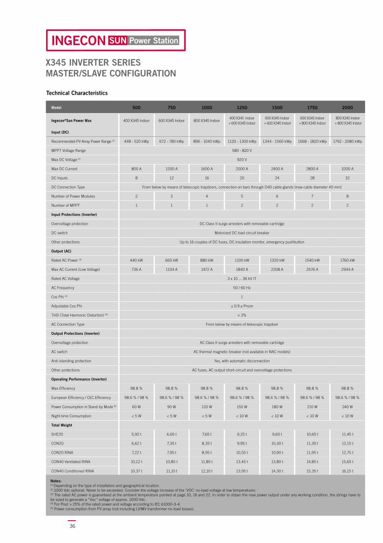
X345 INVERTER SERIESMASTER/SLAVE CONFIGURATION
Model 500 750 1000 1250 1500 1750 2000
Ingecon®Sun Power Max 400 X345 Indoor 600 X345 Indoor 800 X345 Indoor400 X345 Indoor
+ 600 X345 Indoor600 X345 Indoor
+ 600 X345 Indoor600 X345 Indoor
+ 800 X345 Indoor800 X345 Indoor
+ 800 X345 Indoor
Input (DC)
Recommended PV Array Power Range (1) 448 - 520 kWp 672 - 780 kWp 896 - 1040 kWp 1120 - 1300 kWp 1344 - 1560 kWp 1568 - 1820 kWp 1792 - 2080 kWp
MPPT Voltage Range 580 - 820 V
Max DC Voltage (2) 920 V
Max DC Current 800 A 1200 A 1600 A 2000 A 2400 A 2800 A 3200 A
DC Inputs 8 12 16 20 24 28 32
DC Connection Type From below by means of telescopic trapdoors, connection on bars through D40 cable glands (max cable diameter 40 mm)
Number of Power Modules 2 3 4 5 6 7 8
Number of MPPT 1 1 1 2 2 2 2
Input Protections (Inverter)
Overvoltage protection DC Class II surge arresters with removable cartridge
DC switch Motorized DC load circuit breaker
Other protections Up to 16 couples of DC fuses, DC insulation monitor, emergency pushbutton
Output (AC)
Rated AC Power (3) 440 kW 660 kW 880 kW 1100 kW 1320 kW 1540 kW 1760 kW
Max AC Current (Low Voltage) 736 A 1104 A 1472 A 1840 A 2208 A 2576 A 2944 A
Rated AC Voltage 3 x 10 ... 36 kV IT
AC Frequency 50 / 60 Hz
Cos Phi (4) 1
Adjustable Cos Phi ± 0.9 a Pnom
THD (Total Harmonic Distortion) (4) < 3%
AC Connection Type From below by means of telescopic trapdoor
Output Protections (Inverter)
Overvoltage protection AC Class II surge arresters with removable cartridge
AC switch AC thermal magnetic breaker (not available in NAC models)
Anti-islanding protection Yes, with automatic disconnection
Other protections AC fuses, AC output short-circuit and overvoltage protections
Operating Performance (Inverter)
Max Efficiency 98.8 % 98.8 % 98.8 % 98.8 % 98.8 % 98.8 % 98.8 %
European Efficiency / CEC Efficiency 98.6 % / 98 % 98.6 % / 98 % 98.6 % / 98 % 98.6 % / 98 % 98.6 % / 98 % 98.6 % / 98 % 98.6 % / 98 %
Power Consumption in Stand-by Mode (5) 60 W 90 W 120 W 150 W 180 W 210 W 240 W
Night-time Consumption < 5 W < 5 W < 5 W < 10 W < 10 W < 10 W < 10 W
Total Weight
SHE20 5,92 t 6,65 t 7,65 t 9,25 t 9,60 t 10,65 t 11,45 t
CON20 6,62 t 7,35 t 8,35 t 9,95 t 10,30 t 11,35 t 12,15 t
CON20 RINA 7,22 t 7,95 t 8,95 t 10,55 t 10,90 t 11,95 t 12,75 t
CON40 Ventilated RINA 10,12 t 10,85 t 11,85 t 13,45 t 13,80 t 14,85 t 15,65 t
CON40 Conditioned RINA 10,37 t 11,10 t 12,10 t 13,95 t 14,30 t 15,35 t 16,15 t
Notes: (1) Depending on the type of installation and geographical location.(2) 1000 Vdc optional. Never to be exceeded. Consider the voltage increase of the ‘VOC’ no-load voltage at low temperatures.(3) The rated AC power is guaranteed at the ambient temperature pointed at page 10, 16 and 22. In order to obtain the max power output under any working condition, the strings have to be sized to generate a “Voc” voltage of approx. 1000 Vdc.(4) For Pout > 25% of the rated power and voltage according to IEC 61000-3-4.(5) Power consumption from PV array (not including LV/MV transformer no-load losses).
Technical Characteristics

37
Power Station
X360 INVERTER SERIESMASTER/SLAVE CONFIGURATION
Model 525 800 1050 1300 1600 1850 2100
Ingecon®Sun Power Max 420 X360 Indoor 630 X360 Indoor 840 X360 Indoor420 X360 Indoor
+ 630 X360 Indoor630 X360 Indoor
+ 630 X360 Indoor630 X360 Indoor
+ 840 X360 Indoor730 X360 Indoor
+ 840 X360 Indoor
Input (DC)
Recommended PV Array Power Range (1) 466 - 546 kWp 700 - 819 kWp 933 - 1092 kWp 1166 - 1365 kWp 1400 - 1638 kWp 1633 - 1911 kWp 1866 - 2184 kWp
MPPT Voltage Range 606 - 820 V
Max DC Voltage (2) 920 V
Max DC Current 800 A 1200 A 1600 A 2000 A 2400 A 2800 A 3200 A
DC Inputs 8 12 16 20 24 28 32
DC Connection Type From below by means of telescopic trapdoors, connection on bars through D40 cable glands (max cable diameter 40 mm)
Number of Power Modules 2 3 4 5 6 7 8
Number of MPPT 1 1 1 2 2 2 2
Input Protections (Inverter)
Overvoltage protection DC Class II surge arresters with removable cartridge
DC switch Motorized DC load circuit breaker
Other protections Up to 16 couples of DC fuses, DC insulation monitor, emergency pushbutton
Output (AC)
Rated AC Power (3) 458 kW 688 kW 917 kW 1146 kW 1376 kW 1605 kW 1834 kW
Max AC Current (Low Voltage) 736 A 1104 A 1472 A 1840 A 2208 A 2576 A 2944 A
Rated AC Voltage 3 x 10 ... 36 kV IT
AC Frequency 50 / 60 Hz
Cos Phi (4) 1
Adjustable Cos Phi ± 0.9 a Pnom
THD (Total Harmonic Distortion) (4) < 3%
AC Connection Type From below by means of telescopic trapdoor
Output Protections (Inverter)
Overvoltage protection AC Class II surge arresters with removable cartridge
AC switch AC thermal magnetic breaker (not available in NAC models)
Anti-islanding protection Yes, with automatic disconnection
Other protections AC fuses, AC output short-circuit and overvoltage protections
Operating Performance (Inverter)
Max Efficiency 98.8 % 98.8 % 98.8 % 98.8 % 98.8 % 98.8 % 98.8 %
European Efficiency / CEC Efficiency 98.7 % / 98.1 % 98.7 % / 98.1 % 98.7 % / 98.1 % 98.7 % / 98.1 % 98.7 % / 98.1 % 98.7 % / 98.1 % 98.7 % / 98.1 %
Power Consumption in Stand-by Mode (5) 60 W 90 W 120 W 150 W 180 W 210 W 240 W
Night-time Consumption < 5 W < 5 W < 5 W < 10 W < 10 W < 10 W < 10 W
Total Weight
SHE20 5,92 t 6,65 t 7,65 t 9,25 t 9,60 t 10,65 t 11,45 t
CON20 6,62 t 7,35 t 8,35 t 9,95 t 10,30 t 11,35 t 12,15 t
CON20 RINA 7,22 t 7,95 t 8,95 t 10,55 t 10,90 t 11,95 t 12,75 t
CON40 Ventilated RINA 10,12 t 10,85 t 11,85 t 13,45 t 13,80 t 14,85 t 15,65 t
CON40 Conditioned RINA 10,37 t 11,10 t 12,10 t 13,95 t 14,30 t 15,35 t 16,15 t
Notes: (1) Depending on the type of installation and geographical location.(2) 1000 Vdc optional. Never to be exceeded. Consider the voltage increase of the ‘VOC’ no-load voltage at low temperatures.(3) The rated AC power is guaranteed at the ambient temperature pointed at page 10, 16 and 22. In order to obtain the max power output under any working condition, the strings have to be sized to generate a “Voc” voltage of approx. 1000 Vdc.(4) For Pout > 25% of the rated power and voltage according to IEC 61000-3-4.(5) Power consumption from PV array (not including LV/MV transformer no-load losses).
Technical Characteristics

38
The BT-POWER Base low voltage parallel switchgear allows connecting the inverters of the Ingecon®Sun Power Station to the LV/MV step-up transformer.
Upon request, it can be supplied with voltage transformers and current transformers for fi scal energy metering. Moreover, it can also be equipped with a general parallel disconnector.
BT-POWER BASE Low Voltage Parallel Switchgear
BT-POWER BASE Low Voltage Parallel Switchgear
Standard functions:
400 A switch with fuses at each input.
Functions available upon request:
Switch disconnector from 1250 A to 3200 A
Voltage transformer and current transformer for energy fi scal metering

39
The BT-POWER Full low voltage parallel switchgear allows connecting the inverters of the Ingecon®Sun Power Station to the LV/MV step-up transformer.
Upon request, it can be supplied with voltage transformers and current transformers for fi scal energy metering. Moreover, it can also be equipped with a switch operating as an interface device, if a LV interface protection is required.
BT-POWER FULL Low Voltage Parallel Switchgear
BT-POWER FULL Low Voltage Parallel Switchgear
Standard functions:
400 A automatic switch at each input
Current-operated release coil (for backup function)
Functions available upon request:
Motorized switch from 1250 A to 3200 A
Current-operated release coil (for backup function)
Minimum voltage coil (as interface protection device)
RS485 communication system for the motorized switch
Measurement module on motorized switch
Voltage transformer (VT) and current transformer (CT) for fi scal energy metering

40
BT-AUX BASE Auxiliary Services SwitchgearThe BT-AUX BASE auxiliary services switchgear is an added value for the Ingecon®Sun PowerStation since it makes it unnecessary to implement any further wiring for the operation and monitoring of the additional equipment.Besides the wide range of standard functions, other options can be requested when ordering the product.
BT-AUX BASE Auxiliary Services Switchgear
Standard functions:
General circuit breaker on the power supply of the BT-AUX BASE switchgear.
Class II surge arresters with removable cartridge.
AC/DC 24V power supply for the auxiliary circuits of the instruments and monitoring devices.
Fuses and contactors on the power supply of the Ingecon®Sun Power Station ventilation system, which is automatically powered only under specifi c thermal conditions.
Fuses on the power supply of the BT POWER switchgear auxiliary services.
Fuses on the power supply of the Inverter auxiliary services.
Fuses on the power supply of the MV switchgear auxiliary services.
Residual current device on the power supply of the internal lighting system and power outlets.
Fuses on the UPS power supply (UPS excluded)
Fuses on the power supply of the BT-POWER privileged circuits;
Fuses on the power supply of the Ingecon®Sun Combox and monitoring system;
Fuses on the power supply of the privileged circuits of the Inverters;
RS485 Modbus RTU network with DAT3590 signal amplifi er (x2 DAT3590 for Ingecon®Sun Power Station with number of Power Blocks ≥ 5)
Ready for the implementation of a NT935 thermometric control unit (NT538 in case of transformers with double secondary winding) for the protection of the MV transformer, including:
MV line disconnection in case of overheating;
alarm contact wired to the terminal board;
RS485 Modbus RTU serial communication.
Ready for the implementation of a 1000Vdc insulation detector on the secondary winding of the MV transformer (x2 for transformers with double secondary winding):
Light indicator on the front of the boards;
alarm contact wired to the terminal board.
Ready for the implementation of an interface relay for CEI 0-16 function
x1 RS485 Modbus RTU interface
x1 ETHERNET interface - EC 61850 protocol
Automatic reset system
Functions available upon request:NT935 thermometric control unit (NT538 in case of transformers with double secondary winding).
LV/LV transformer for the powering of the auxiliary switchgear BT-AUX BASE.
1000 Vdc insulation detector on the secondary winding of the MV transformer (x2 for transformers with double secondary winding).
UPS for auxiliary services.
Interface relay for CEI 0-16 function, with open delta voltage measurement on MV side, via voltage transformer or sensors.
41
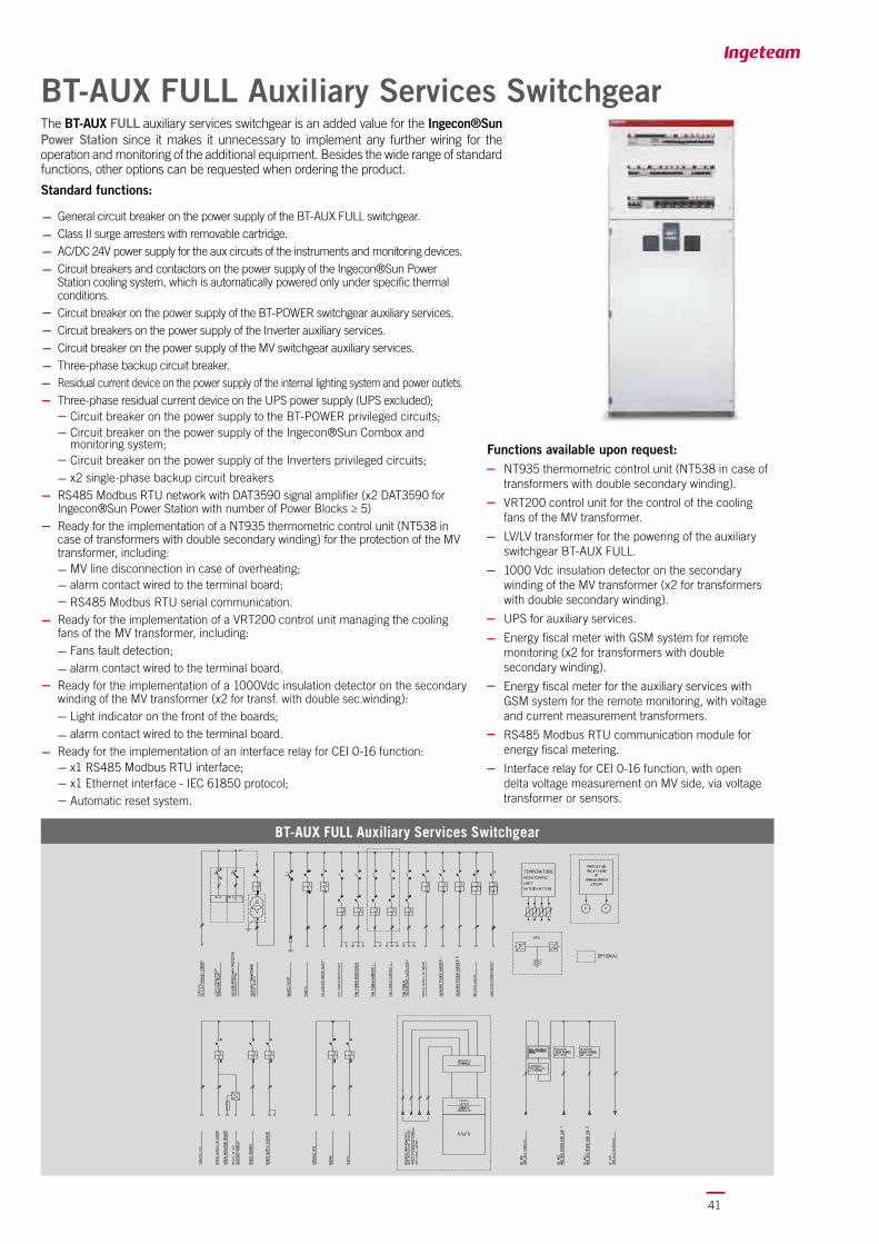
BT-AUX FULL Auxiliary Services Switchgear
BT-AUX FULL Auxiliary Services Switchgear
The BT-AUX FULL auxiliary services switchgear is an added value for the Ingecon®Sun Power Station since it makes it unnecessary to implement any further wiring for the operation and monitoring of the additional equipment. Besides the wide range of standard functions, other options can be requested when ordering the product.
Standard functions:
General circuit breaker on the power supply of the BT-AUX FULL switchgear.Class II surge arresters with removable cartridge.AC/DC 24V power supply for the aux circuits of the instruments and monitoring devices.Circuit breakers and contactors on the power supply of the Ingecon®Sun Power Station cooling system, which is automatically powered only under specifi c thermal conditions. Circuit breaker on the power supply of the BT-POWER switchgear auxiliary services.Circuit breakers on the power supply of the Inverter auxiliary services.Circuit breaker on the power supply of the MV switchgear auxiliary services.Three-phase backup circuit breaker.Residual current device on the power supply of the internal lighting system and power outlets.Three-phase residual current device on the UPS power supply (UPS excluded);
Circuit breaker on the power supply to the BT-POWER privileged circuits;Circuit breaker on the power supply of the Ingecon®Sun Combox and monitoring system;Circuit breaker on the power supply of the Inverters privileged circuits;x2 single-phase backup circuit breakers
RS485 Modbus RTU network with DAT3590 signal amplifi er (x2 DAT3590 for Ingecon®Sun Power Station with number of Power Blocks ≥ 5)Ready for the implementation of a NT935 thermometric control unit (NT538 in case of transformers with double secondary winding) for the protection of the MV transformer, including:
MV line disconnection in case of overheating;alarm contact wired to the terminal board;RS485 Modbus RTU serial communication.
Ready for the implementation of a VRT200 control unit managing the cooling fans of the MV transformer, including:
Fans fault detection;alarm contact wired to the terminal board.
Ready for the implementation of a 1000Vdc insulation detector on the secondary winding of the MV transformer (x2 for transf. with double sec.winding):
Light indicator on the front of the boards;alarm contact wired to the terminal board.
Ready for the implementation of an interface relay for CEI 0-16 function:x1 RS485 Modbus RTU interface;x1 Ethernet interface - IEC 61850 protocol;Automatic reset system.
Functions available upon request:NT935 thermometric control unit (NT538 in case of transformers with double secondary winding).
VRT200 control unit for the control of the cooling fans of the MV transformer.
LV/LV transformer for the powering of the auxiliary switchgear BT-AUX FULL.
1000 Vdc insulation detector on the secondary winding of the MV transformer (x2 for transformers with double secondary winding).
UPS for auxiliary services.
Energy fi scal meter with GSM system for remote monitoring (x2 for transformers with double secondary winding).
Energy fi scal meter for the auxiliary services with GSM system for the remote monitoring, with voltage and current measurement transformers.
RS485 Modbus RTU communication module for energy fi scal metering.
Interface relay for CEI 0-16 function, with open delta voltage measurement on MV side, via voltage transformer or sensors.

42
Medium Voltage Transformer
Ingeteam provides highly performing LV/MV three phase dry type transformers, with epoxy resin vacuum cast windings. Power ratings are available up to 2 MVA, with voltage ratings (MV side) from 10 up to 24 kVA (up to 36 kVA on the Ingecon®Sun Power Station CON40).
The transformers are F1-C2-E2 classifi ed as per the CEI EN 60076-11 standard, offering the following benefi ts:
Self-extinguishing, with low smoke emission (F1);
Resistance to climatic variations (C2);
Resistance to humidity and atmospheric pollution (E2);
Reduced maintenance needs;
Flexibility: no foundations required, easy handling.
The voltage value at the secondary winding (LV side) is compatible with the inverter output voltage: 220 V, 275 V, 300 V, 320 V, 345 V, 360 V.
Standard functions:
Standard losses;
Electrostatic shield reducing disturbances, distortions and overvoltages.
Functions available upon request:
Reduced losses;
Forced ventilation.
Medium Voltage Transformer
Category Cast-resin transformer
Rated frequency 50 / 60Hz
Primary voltage regulator ± 2 x 2.5 %
Insulation class Primary winding 24/50/125 kV - Secondary winding 1.1/3 kV
Or Primary winding 36/70/170 kV - Secondary winding 1.1/3 kV (1)
Primary / secondary conductive material Aluminium / Aluminium
Primary / secondary winding protection Cast resin / Resin impregnated
Vector group Dyn11
Primary connection Delta
Secondary connection Star + Neutral
Environmental, climatic and fi re classes E2 / C2 / F1 (CESI certifi cation as per the new standard IEC 60076-11 year 2004)
Thermal class F / F
Max overtemperature for primary / secondary windings 100 / 100 K
Installation Indoor
Cooling type Natural air
Cooling system (optional) Forced ventilation
Altitude above sea level(2) ≤ 1000 m
Short-circuit impedance at 75°C 6% (24kV)
Partial discharge level ≤ 10 pC
General features x3 terminal boards for primary voltage adjustment (5 positions), x4 LV connection plates, x2 earthing terminal boards, x2 lifting lugs, x4 rotating wheels, x1 connection box, x3 PT100 temperature probes,
electrostatic shield.
Notes: (1) CON40 models only. - (2) For Higher altitudes, please contact Ingeteam.
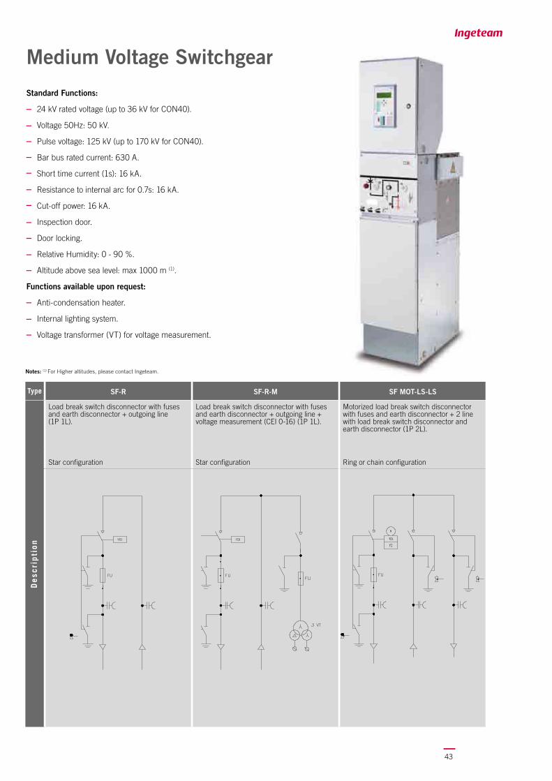
43
Medium Voltage Switchgear
Standard Functions:
24 kV rated voltage (up to 36 kV for CON40).
Voltage 50Hz: 50 kV.
Pulse voltage: 125 kV (up to 170 kV for CON40).
Bar bus rated current: 630 A.
Short time current (1s): 16 kA.
Resistance to internal arc for 0.7s: 16 kA.
Cut-off power: 16 kA.
Inspection door.
Door locking.
Relative Humidity: 0 - 90 %.
Altitude above sea level: max 1000 m (1).
Functions available upon request:
Anti-condensation heater.
Internal lighting system.
Voltage transformer (VT) for voltage measurement.
Type SF-R SF-R-M SF MOT-LS-LS
Load break switch disconnector with fuses and earth disconnector + outgoing line (1P 1L).
Load break switch disconnector with fuses and earth disconnector + outgoing line + voltage measurement (CEI 0-16) (1P 1L).
Motorized load break switch disconnector with fuses and earth disconnector + 2 line with load break switch disconnector and earth disconnector (1P 2L).
Star confi guration Star confi guration Ring or chain confi guration
De
scri
pti
on
Notes: (1) For Higher altitudes, please contact Ingeteam.

44
Type E2-R-M E3-R
Automatic motorized circuit breaker with 50, 51 and 51N CEI 0-16 and earth disconnector + outgoing line + voltage measurement (CEI 0-16) (1P 1L).
Automatic motorized circuit breaker with functions 50, 51, 51N and 67N CEI 0-16 and earth disconnector + outgoing line (1P 1L).
Star configuration Star configuration
Type VST-R VST-R-M VST-LS-LS
Automatic motorized circuit breaker with 50 and 51 functions and earth disconnector + outcoming line (1P 1L).
Automatic motorized circuit breaker with 50 and 51 functions and earth disconnector + outgoing line + voltage measurement (CEI 0-16) (1P 1L).
Automatic motorized circuit breaker with 50 and 51 functions and earth disconnector + 2 line with load break switch disconnector and earth disconnector (1P 2L).
Star configuration Star configuration Ring or chain configuration
De
scri
pti
on
De
scri
pti
on

45
Type E2 UTF-R E3-LS MOT-LS MOT
Automatic motorized circuit breaker functions 50, 51 and 51N CEI 0-16 with CT and VT for energy metering and earth disconnector + outgoing riser (1P 1L).
Automatic motorized circuit breaker with functions 50, 51, 51N and 67N CEI 0-16 and earth disconnector + 2 line with load break switch disconnector and earth disconnector (1P 2L).
Star configuration Ring or chain configuration
De
scri
pti
on
Type E2 PI-SF/V-R E2 PI UTF-SF/V-R
Automatic motorized circuit breaker with functions 50, 51 and 51N, interface protection CEI 0-16 and earth disconnector + voltage measurement (CEI 0-16) + outgoing line (1P 1L).
Automatic motorized circuit breaker functions 50, 51 and 51N, in-terface protection CEI 0-16 with CT and VT for energy metering and earth disconnector + voltage measurement (CEI 0-16) + outgoing line (1P 1L).
Star configuration Star configuration
De
scri
pti
on

46
Type SF MOT-R-LS VST-R-LS
Motorized load break switch disconnector with fuses and earth disconnector + 1 incoming line + 1 outgoing line with load break switch disconnector and earth disconnector (1P 2L).
Automatic motorized circuit breaker with functions 50 and 51 and earth disconnector + 1 incoming line + 1 outgoing line with load break switch disconnector and earth disconnector (1P 2L).
Ring or chain configuration Ring or chain configuration
Type E2-R SF MOT-LS MOT-E3
Automatic motorized circuit breaker with functions 50, 51 and 51N CEI 0-16 and earth disconnector + outgoing line (1P 1L).
Motorized load break switch disconnector with fuses and earth disconnector + 1 incoming line with load break switch disconnector and earth disconnector + automatic motorized circuit breaker with functions 50, 51, 51N and 67N CEI 0-16 and earth disconnector (1P 2L).
Star configuration Ring or chain configuration
De
scri
pti
on
De
scri
pti
on

47
Ingecon®Sun Power Station - Maxter configuration (Master/Slave)
Ingecon®Sun Power Station - Multi-MPPT configuration
Basic wiring diagrams

48
POWER STATION type
20 ft SHELTER SHE20
20 ft CONTAINER CON20
40 ft CONTAINER CON40
POWER STATION power
Power in kWp applicable to the Power Station 300 .... 2100
INVERTER range
Ingecon®Sun Power Max (Multi MPPT) M220…M360
Ingecon®Sun Power Maxter
(Master/Slave)X220…X360
Example: Ingecon®Sun Power Station
Power Station Coding
POWER STATION cooling
Forced ventilation V
Air conditioning with Free Cooling system C
Power Block INVERTER
Number of Power Modules 2...8
INVERTER MPPT
MPPT number (max 2 for X series) 1...8
INVERTER inputs
Number of inverter inputs
F(n°)=couple of fuses per input 63…250A
B(n°)=couple of fuses every four inputs 550A
F8…F32
B8…B32
BT POWER parallel switchgear
BT POWER inputs quantity
CB(n°)=automatic switch 400A
FSD(n°)=disconnector with fuses 400A
0...CB3…CB80...FSD3…FSD8
BT POWER parallel switchgear
Disconnection device, MV transformer side
0=not present
CB=automatic switch
SD=disconnector
0
CB
SD
BT AUX auxiliary services switchgear
BT AUX switchgear type
0=not present
B=basic model
F=full model
FM(n°)=full model ready for energy metering addition
0
B
F
FM1…2
SHE20 V 2000 M340 8 8 B32

49
MV transformer
Power in kVA 315...1850
MV transformer
Power in kV 10...36
MV transformer
Standard losses N
Reduced losses R
MV Switchgear
not present 0
Switch disconnector with fuses (1P 1L) SF-R
Switch disconnector with fuses + measurement as per CEI 0-16 (1P 1L)
SF-R-M
Motorized switch disconnector with fuses + in-out disconnectors for ring or chain (1P 2L)
SF MOT-LS-LS
Motorized switch disconnector with fuses + disconnector and in-out riser for ring or chain (1P 2L)
SF MOT-R-LS
Motorized switch disconnector with fuses + disconnector and motorized automatic circuit breaker functions 50, 51, 51N, 67N CEI 0-16 (1P 2L)
SF MOT-LS MOT-E3
Motorized automatic circuit breaker (1P 1L) VST-R
Motorized automatic circuit breaker + measurement as per CEI 0-16 (1P 1L)
VST-R-M
Motorized automatic circuit breaker + in-out disconnectors for ring or chain (1P 2L)
VST-LS-LS
Motorized automatic circuit breaker + disconnector and in-out riser for ring or chain (1P 2L)
VST-R-LS
Motorized automatic circuit breaker functions 50, 51, 51N CEI 0-16 (1P 1L)
E2-R
Motorized automatic circuit breaker functions 50, 51, 51N CEI 0-16 + measurement as per CEI 0-16 (1P 1L)
E2-R-M
Motorized automatic circuit breaker functions 50, 51, 51N, 67N CEI 0-16 (1P 1L)
E3-R
Motorized automatic circuit breaker functions 50, 51, 51N CEI 0-16 + energy metering measurements (1P 1L)
E2 UTF-R
Motorized automatic circuit breaker functions 50, 51, 51N, 67N CEI 0-16 + motorized in-out disconnectors for ring or chain (1P 2L)
E3-LS MOT-LS MOT
Motorized automatic circuit breaker functions 50, 51, 51N CEI 0-16 + measurement and interface as per CEI 0-16 (1P 1L)
E2 PI-SF/V-R
Motorized automatic switch disconnector functions 50, 51, 51N CEI 0-16 + energy metering measurements + measurement and interface as per CEI 0-16 (1P 1L)
E2 PI UTF-SF/V-R
CB8 0 FM1 1850 20 N SF-R


Ingeteam Power Technology, S.A.Avda. Ciudad de la Innovación , 13
31621 SARRIGUREN (Navarra) - SpainTel.: +34 948 28 80 00Fax.: +34 948 28 80 01
e-mail: [email protected]
Ingeteam S.r.l.Via Emilia Ponente, 232
48014 CASTEL BOLOGNESE (RA) - ItalyTel.: +39 0546 651 490
Fax.: +39 054 665 5391e-mail: [email protected]
www.ingeteam.it
Ingeteam GmbHHerzog-Heinrich-Str. 10
80336 MUNICH - GermanyTel.: +49 89 99 65 38 0
Fax.: +49 89 99 65 38 99e-mail: [email protected]
Ingeteam SASParc Innopole
BP 87635 - 3 rue Carmin - Le Naurouze B5F- 31676 Toulouse Labège cedex - France
Tel: +33 (0)5 61 25 00 00Fax: +33 (0)5 61 25 00 11
e-mail: [email protected]
Ingeteam INC.5201 Great American Parkway, Suite 320
SANTA CLARA, CA 95054 - USATel.: +1 (408) 524 2929Fax.: +1 (408) 824 1327
e-mail: [email protected]
Ingeteam INC.1025 W. Glen Oaks Lane, Suite 102
MEQUON, WI 53092 - USATel.: +1 (262) 240 9850
Fax.: +1 (262) 240 9854e-mail: [email protected]
Ingeteam, a.s.Technologická 371/1
70800 OSTRAVA - PUSTKOVECCzech Republic
Tel.: +420 59 732 6800Fax.: +420 59 732 6899
e-mail: [email protected]
Ingeteam Shanghai, Co. Ltd.Shanghai Trade Square, 1105
188 Si Ping Road200086 SHANGHAI - P.R. China
Tel.. +86 21 65 07 76 36Fax.: +86 21 65 07 76 38
e-mail: [email protected]
Ingeteam, S.A. de C. V.Calle Tlaquepaque, nº 4871
Colonia Los Altos - MONTERREYCP64370 NUEVO LEÓN - Mexico
Tel.: +52 81 8311 4858 Fax.: +52 81 8311 4859
e-mail: [email protected]
Ingeteam Ltda.Rua Luiz Carlos Brunello, 286
Chácara Sao Bento13278-074 VALINHOS SP - Brazil
Tel.: +55 19 3037 3773 Fax.: +55 19 3037 3774
e-mail: [email protected]
Ingeteam Power Technology, S.A.
www.ingeteam.com
Ref: 06/2012 rev:4ENG Information subject to change without notice