Photorealistic rendering of a graded negative-index
11
PAPER Photorealistic rendering of a graded negative- index metamaterial magnifier To cite this article: Cheng-Wei Qiu et al 2012 New J. Phys. 14 033024 View the article online for updates and enhancements. You may also like Practical Bayesian tomography Christopher Granade, Joshua Combes and D G Cory - Study of broadband multimode light via non-phase-matched sum frequency generation Denis A Kopylov, Kirill Yu Spasibko, Tatiana V Murzina et al. - Chiral switching and dynamic barrier reductions in artificial square ice Naëmi Leo, Matteo Pancaldi, Sabri Koraltan et al. - Recent citations Anamorphic fractional Fourier transforms graded index lens designed using transformation optics Xiao-bo Yang and Jin Hu - Analytical study of mismatched complementary media Lin Zhu et al - Large-scale, white-light, transformation optics using integral imaging Stephen Oxburgh et al - This content was downloaded from IP address 156.34.42.21 on 16/11/2021 at 23:34
Transcript of Photorealistic rendering of a graded negative-index
PAPER
Photorealistic rendering of a graded negative-index metamaterial magnifierTo cite this article: Cheng-Wei Qiu et al 2012 New J. Phys. 14 033024
View the article online for updates and enhancements.
You may also likePractical Bayesian tomographyChristopher Granade, Joshua Combesand D G Cory
-
Study of broadband multimode light vianon-phase-matched sum frequencygenerationDenis A Kopylov, Kirill Yu Spasibko,Tatiana V Murzina et al.
-
Chiral switching and dynamic barrierreductions in artificial square iceNaëmi Leo, Matteo Pancaldi, SabriKoraltan et al.
-
Recent citationsAnamorphic fractional Fourier transformsgraded index lens designed usingtransformation opticsXiao-bo Yang and Jin Hu
-
Analytical study of mismatchedcomplementary mediaLin Zhu et al
-
Large-scale, white-light, transformationoptics using integral imagingStephen Oxburgh et al
-
This content was downloaded from IP address 156.34.42.21 on 16/11/2021 at 23:34
T h e o p e n – a c c e s s j o u r n a l f o r p h y s i c s
New Journal of Physics
Photorealistic rendering of a graded negative-indexmetamaterial magnifier
Cheng-Wei Qiu1, Alireza Akbarzadeh, Tiancheng Hanand Aaron J DannerDepartment of Electrical and Computer Engineering, National University ofSingapore, Kent Ridge, Singapore 119620, Republic of SingaporeE-mail: [email protected]
New Journal of Physics 14 (2012) 033024 (10pp)Received 11 December 2011Published 14 March 2012Online at http://www.njp.org/doi:10.1088/1367-2630/14/3/033024
Abstract. A novel reverse design schematic for designing a metamaterialmagnifier with graded negative refractive index for both the two-dimensional andthree-dimensional cases has been proposed. Photorealistic rendering is integratedwith trace ray trajectories in example designs to visualize the scatteringmagnification as well as imaging of the proposed graded-index magnifierwith negative-index metamaterials. The material of the magnifying shell canbe uniquely and independently determined without knowing beforehand thecorresponding domain deformation. This reverse recipe and photorealisticrendering directly tackles the significance of all possible parametric profiles anddemonstrates the performance of the device in a realistic scene, which providesa scheme to design, select and evaluate a metamaterial magnifier.
S Online supplementary data available from stacks.iop.org/NJP/14/033024/mmedia
Contents
1. Introduction 22. Two-dimensional design 33. Three-dimensional design 64. Conclusion 9Acknowledgments 10References 101 Author to whom any correspondence should be addressed.
New Journal of Physics 14 (2012) 0330241367-2630/12/033024+10$33.00 © IOP Publishing Ltd and Deutsche Physikalische Gesellschaft
2
1. Introduction
Conformal mapping [1] and coordinate transformations [2] have been developed to derivethe required parameters in optical instruments with pre-defined functionality. These methodspave an unprecedented avenue to various conceptual devices that possess exotic control overthe propagation of electromagnetic (EM) waves. Among those rational designs with novelmanipulation of EM waves, cloaking, which makes objects invisible, has been attractingincreasing attention, especially because metamaterials are found to be a potential candidateto realize the cloaks [3]. Practical attempts to realize a cylindrical cloak have been made inthe microwave [4] and optical [5] regimes. The coordinate transformation employed relieson the invariance of Maxwell’s equations throughout the spatial transformation. A variety ofapplications have been studied such as carpet cloaks [6], external cloaks [7], superscatteringand shifting effects [8], beam splitters [9], homogeneous nonmagnetic bends [10] and fieldcollimators [11], which have been reviewed in [12]. Instead of cloaking an object (i.e. shrinkingthe scattering cross section of the object), a magnifier is of great interest to the scientificcommunity in the other extreme. The magnifier could form an image exceeding the physical sizeof the object. Transformation optics have been applied to design cylindrical superscatterers [13],and the concept of complementary illusion optics has been used in conjunction with atransmission line circuit to achieve superscattering [14], although the enlargement of scatteringcross section is mimicked by the voltage measured on the circuit board. Graded-index materialsderived from transformation optics have been used in [15] to magnify subwavelength featuresof an object for the purpose of super-resolution, although only a virtual image rather than areal image can be provided via the proposed method. As has been addressed in [16], practicallimitations of dissipation and loss upon realizing cloaks need to be considered in fabrication. Inthis respect, more recently, low-loss dielectric cloaks have been fabricated by the use of calcites,which further overcomes the loss problem [17].
Nevertheless, previous transformation-optic methods require knowledge of the spatialtransformation first, so as to derive the corresponding parameters for simulations and ex-periments. In our reverse design of the two-dimensional (2D) and three-dimensional (3D)metamaterial magnifiers, there is, by the nature of the space compression, an infinite number ofpossible transformation functions, all of which can lead to identical magnifying functionality.However, because of practical limitations of fabrication and consideration of the cost, it isbetter to wisely select a model which has less stringent parameters and/or is easier to realize bycurrent fabrication techniques. It is due to the fact that the metamaterial technology, althoughdeveloping fast, is still far from being capable enough to produce stealth aircraft or opticalcloak/camouflage perfectly in action. Hence, it is useful to directly envisage the desiredparameters of the metamaterial magnifier (i.e. impose the explicit final parameters first), sincecomplexity and feasibility are predetermined and the photorealistic rendering will furtherfacilitate seeing how those conceptual devices will behave in the practical outdoor environmentand to the best of today’s and futuristic materials. In contrast to usual methods (i.e. knowinga class of transformation functions and then determining the final parameters), we actually flipthe design sequence by presenting a reverse methodology to determine the required parametersof a magnifier, without knowing the specific coordinate transformation beforehand. By directlyanalyzing the parameters and examining whether there is a physical solution to the transforma-tion function, our approach provides a robust tool to evaluate if metamaterial magnifiers can beaccessible and simplified in terms of homogeneity, isotropy, non-singularity, etc. Accordingly,
New Journal of Physics 14 (2012) 033024 (http://www.njp.org/)
3
different designs will be examined and eventually their advantages and disadvantages will beshown. In addition to geometric raytracing, photorealistic raytracing [18] has been used toevaluate grating cloaks. We will employ the photorealistic rendering technique to visualize thescattering magnification and the imaging properties by tracing ray trajectories and also simulatehow such a device behaves in a real environment before it is built.
The advantage of this reverse transformation method is threefold: (i) a generating functiontogether with the boundary conditions, in fact, replaces the corresponding spatial deformation;instead of considering the coordinate transformation directly, the reverse mechanism enablesus to easily derive different parametric profiles by selecting such a generating function, e.g.exponential, Gaussian, quadratic, etc; thus all possible types of magnifiers can be exploredrobustly. (ii) From the parameters obtained in such a reverse method, it is easier to manipulatethe material properties (e.g. isotropy, non-singularity and homogeneity), and finally one candetermine a particular generating function g(r) that gives rise to an isotropic and nonsingularscattering magnifier by the use of graded negative-index materials. (iii) Other optical devicesthat lead to interesting phenomena such as super-resolution imaging and perfect lens canbe designed since the feature image can be greatly enlarged; the proposed integrated recipeprovides insightful access to parameter simplification (e.g. removal of anisotropy, singularityor inhomogeneity), and to the real-life emulation of perfection or imperfection in the devicebefore being built. This reverse design still relies on negative-index materials, even though non-singularity can be avoided and the inhomogeneity in certain material parameters can be muchalleviated. Nevertheless, the reverse design method sheds some light on how to robustly selecta more suitable set of material parameters, and the advanced photorealistic rendering enablesus to perceive and visualize the device performance in the presence of material imperfectionbeforehand due to the fabrication limit.
2. Two-dimensional design
First, let us assume that a circular region (r 6 a) covered by complementary media (a 6 r 6 b)
in physical space �(r) is transformed from a circular region (r ′ 6 c) in virtual space �′(r ′) viaan unknown transformation function. The complementary media are assumed to be equal forimpedance matching, i.e. ε(r) = µ(r) = αr r r + αθ θ θ + αz z z. The geometry is folded along theradial direction, and thus the Jacobian matrix is diagonal, although we still have no informationon what the coordinate transformation is. The relative parameters of the complementary media
can be obtained: ε = µ = A · AT/ det(A) [1, 2], where A = ∂(r, θ, z)/∂(r ′, θ ′, z′) is the Jacobian
matrix, and (r ′, θ ′, z′) and (r, θ, z) represent the EM space and the physical space, respectively.Then, three principal values of ε(r) and µ(r) can be derived: αr =
r ′ drr dr ′ , αθ =
1αr
and αz =r ′ dr ′
r dr .By making use of the identities αrαz = (r ′/r)2 and r
√αrαz∂[r
√αrαz]/∂r = rαz, one can obtain
r ′2= C0 + 2
∫ r
ar1αz(r1) dr1, (1)
where C0 is a constant. Due to the folding configuration (r ′= c when r = a), we have C0 = c2
from equation (1). Another condition (r ′= b when r = b) leads to the normalization∫ b
ar1αz(r1) dr1 =
b2− c2
2. (2)
New Journal of Physics 14 (2012) 033024 (http://www.njp.org/)
4
Here, we introduce the generating function g(r) which is proportional to αz(r), i.e. αz(r) =
d0g(r), where d0 is an arbitrary constant. Substituting αz(r) = d0g(r) into equation (2), we canobtain d0 = (b2
− c2)/[2∫ b
a r1g(r1) dr1]. Thus αz(r) can be expressed as
αz(r) =(b2
− c2)g(r)
2∫ b
a r1g(r1) dr1
. (3)
From the aforementioned identity αrαz = (r ′/r)2 and equation (3), αr(r) can be determined:
αr(r) =c2 + 2
∫ ra r1αz(r1) dr1
r 2αz(r). (4)
The unknown coordinate transformation for the corresponding complementary media can, inturn, be found.
r ′=
√c2 + 2
∫ r
ar1αz(r1) dr1. (5)
To validate this method, we select a specific generating function as the representativedemonstration, i.e. g(r) = r n (n = 0, ±1, ±2, · · · ). Then αz(r) can be derived.
αz(r) =(n + 2)(b2
− c2)r n
2(bn+2 − an+2)when n 6= −2,
αz(r) =b2
− c2
2r 2 ln(b/a)when n = −2. (6)
Its corresponding coordinate transformation can be expressed as
r ′=
√c2 +
(b2 − c2)(r n+2 − an+2)
bn+2 − an+2when n 6= −2,
r ′=
√c2 +
(b2 − c2) ln(r/a)
ln(b/a)when n = −2. (7)
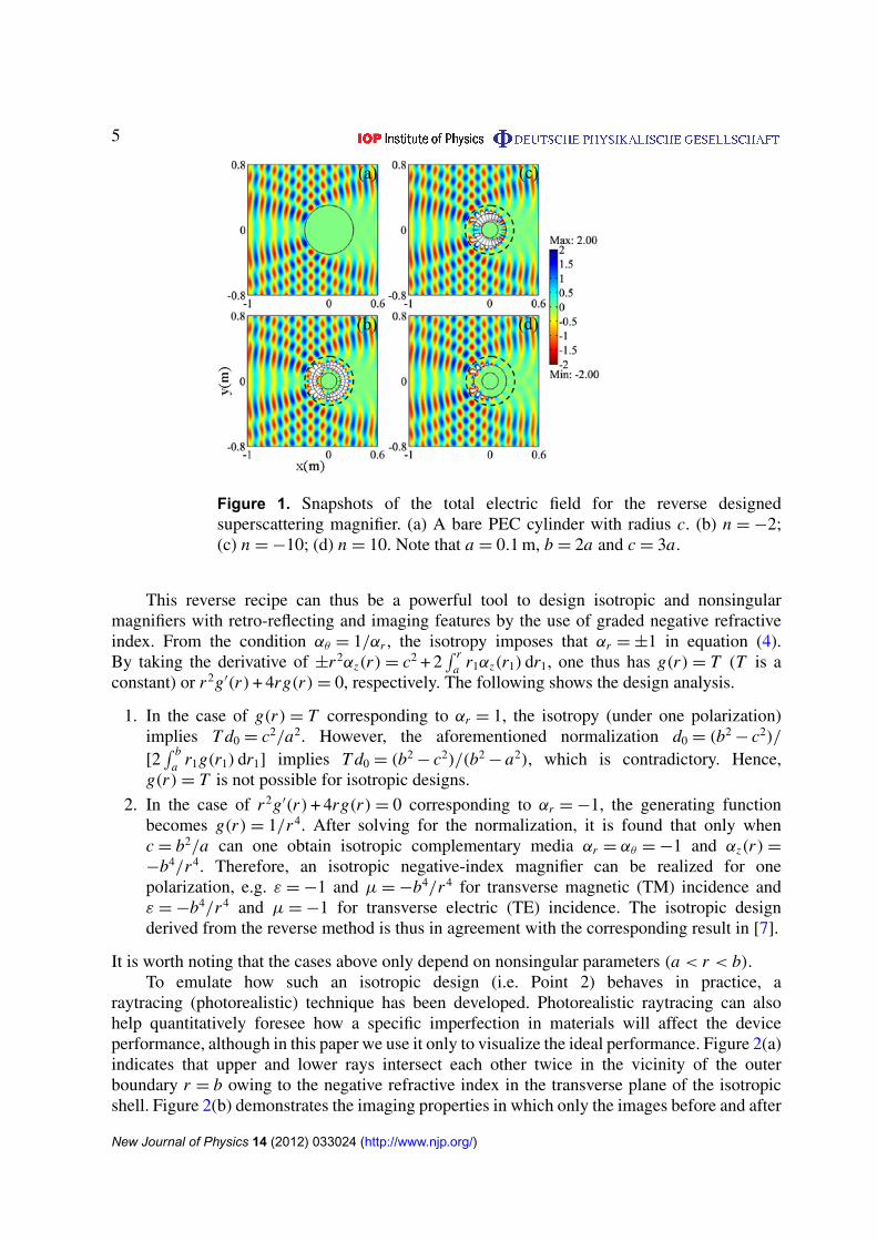
Reverse magnifiers designed with generating functions corresponding to different valuesof n are presented for g(r) = 1/r 2 (i.e. n = −2), g(r) = 1/r 10 (i.e. n = −10) and g(r) = r 10
(i.e. n = 10) in figures 1(b)–(d). It can be found that the electric fields for those three types areequivalent outside the black dashed lines (r > c), where the scattering pattern of a small circularperfect electric conductor (PEC) (r = a) covered by complementary media is equivalent to thatof the bare PEC (r = c) in figure 1(a).
Figure 1(d) reveals that the generating function n = 10, compared to the other two cases,gives rise to the smallest scattering intensity in the complementary media, and the area of whiteflecks is also minimal and confined just near the outer boundary (r = b). It can be explained thatthe implied spatial transformation corresponding to the case of the generating function n = 10will fold and compress more virtual space into the area near the outer boundary in physicalspace, which can be verified by plotting equation (7) for n = 10. It is worth noting that thosehigh-intensity areas are always associated with high heat generation, which is a big problem inreal applications. One potential solution for solving such a heat problem could be to mount acooling fin externally since the high-field-intensity region is pushed to the outer boundary.
New Journal of Physics 14 (2012) 033024 (http://www.njp.org/)
5
Figure 1. Snapshots of the total electric field for the reverse designedsuperscattering magnifier. (a) A bare PEC cylinder with radius c. (b) n = −2;(c) n = −10; (d) n = 10. Note that a = 0.1 m, b = 2a and c = 3a.
This reverse recipe can thus be a powerful tool to design isotropic and nonsingularmagnifiers with retro-reflecting and imaging features by the use of graded negative refractiveindex. From the condition αθ = 1/αr , the isotropy imposes that αr = ±1 in equation (4).By taking the derivative of ±r 2αz(r) = c2 + 2
∫ ra r1αz(r1) dr1, one thus has g(r) = T (T is a
constant) or r 2g′(r) + 4rg(r) = 0, respectively. The following shows the design analysis.
1. In the case of g(r) = T corresponding to αr = 1, the isotropy (under one polarization)implies T d0 = c2/a2. However, the aforementioned normalization d0 = (b2
− c2)/
[2∫ b
a r1g(r1) dr1] implies T d0 = (b2− c2)/(b2
− a2), which is contradictory. Hence,g(r) = T is not possible for isotropic designs.
2. In the case of r 2g′(r) + 4rg(r) = 0 corresponding to αr = −1, the generating functionbecomes g(r) = 1/r 4. After solving for the normalization, it is found that only whenc = b2/a can one obtain isotropic complementary media αr = αθ = −1 and αz(r) =
−b4/r 4. Therefore, an isotropic negative-index magnifier can be realized for onepolarization, e.g. ε = −1 and µ = −b4/r 4 for transverse magnetic (TM) incidence andε = −b4/r 4 and µ = −1 for transverse electric (TE) incidence. The isotropic designderived from the reverse method is thus in agreement with the corresponding result in [7].
It is worth noting that the cases above only depend on nonsingular parameters (a < r < b).To emulate how such an isotropic design (i.e. Point 2) behaves in practice, a
raytracing (photorealistic) technique has been developed. Photorealistic raytracing can alsohelp quantitatively foresee how a specific imperfection in materials will affect the deviceperformance, although in this paper we use it only to visualize the ideal performance. Figure 2(a)indicates that upper and lower rays intersect each other twice in the vicinity of the outerboundary r = b owing to the negative refractive index in the transverse plane of the isotropicshell. Figure 2(b) demonstrates the imaging properties in which only the images before and after
New Journal of Physics 14 (2012) 033024 (http://www.njp.org/)

6
Figure 2. Raytracing of the isotropic negative-index shell whose parameters areε = −b4/r 4and µ = −1. (a) Ray trajectories for light before hitting the PEC(red and blue), after being reflected by the PEC (orange and green); red andorange lines correspond to rays in the upper-half space; blue and green linescorrespond to the rays in the lower half. (b) The images inside the isotropicshell and outside the isotropic shell. Note that a = 0.2 m, b = 2a and c = b2/a.A photorealistic rendering of such an isotropic magnifier is shown in movie 1(available from stacks.iop.org/NJP/14/033024/mmedia), where b is fixed at0.2 m and a is varying up to 0.2 m (i.e. c = b, no magnification).
ray intersection areas are shown. It reveals that the image inside the isotropic shell (A′′B′′C′′D′′)is flipped (left-side right) and the image outside the shell (A′B′C′D′) is preserved, while bothhave their shapes deformed. Hence the image outside the isotropic shell will not be inverted, incontrast to the Eaton lens flipping the image upside down [19].
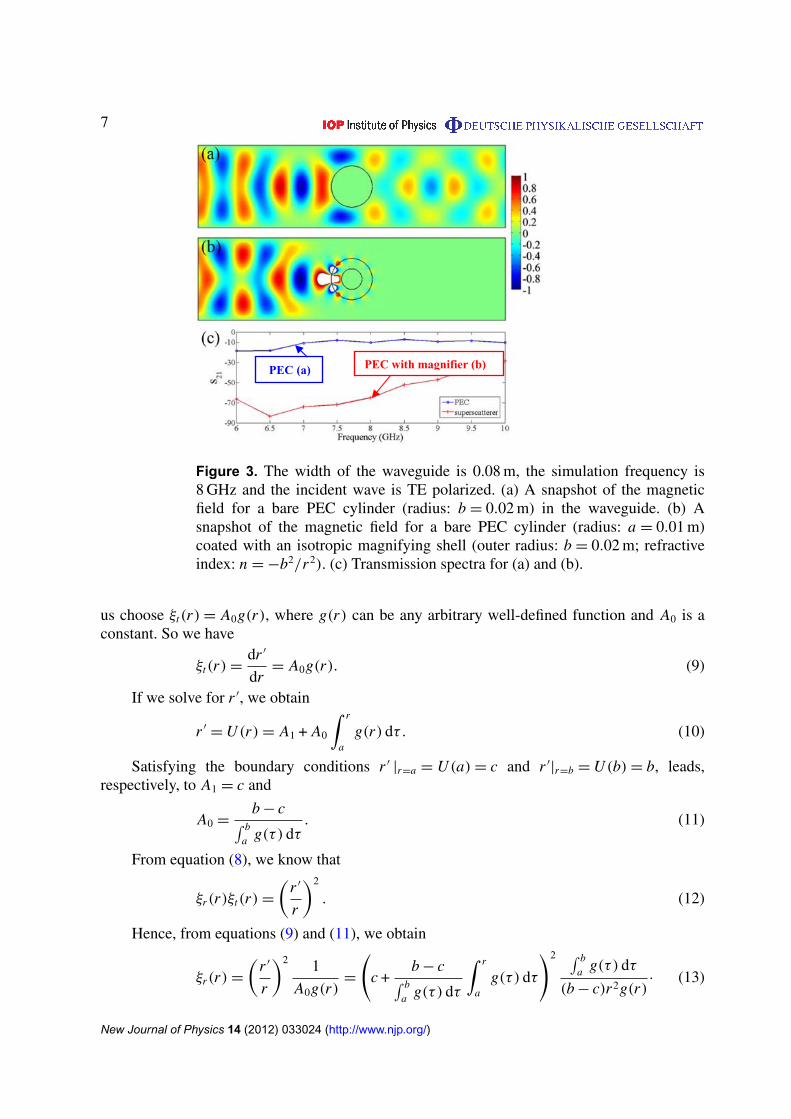
In figure 3(a), a bare PEC rod (r < b) is placed in the waveguide, so the wave will certainlybe partially transmitted via the openings between the PEC rod and the waveguide walls, asshown in figure 3(c). However, in figure 3(b), when a smaller PEC rod (r < a) is coatedby an isotropic shell (a < r < b), the coated rod effectively behaves as a magnified PEC rod(r = 0.04 m). Therefore, even though the coated structure in figure 3(b) has its outermost radiusphysically identical to that in figure 3(a), the PEC in figure 3(b) will be magnified and block thewhole waveguide width (since the width of the waveguide is 0.08 m). This is verified from thefield distribution in figure 3(b) and the transmission spectra in figure 3(c).
3. Three-dimensional design
The reverse design scheme for 2D cases can also be extended to develop 3D magnifiers. Similarto the 2D case, a spherical region (r 6 a) covered by a metamaterial shell (a 6 r 6 b) inphysical space �(r) can be transformed from a spherical region (r ′ 6 c) in virtual space �′(r ′)
via an unknown transformation function.The medium in the magnifying shell (a 6 r 6 b) has the following relative permittivity
and permeability:
ε = µ = diag {ξr , ξt , ξt} = diag{λr/λ
2t , 1/λr , 1/λr
}, (8)
where λr = dr/dr ′ and λt = r/r ′. Since our shrinkage in the spherical coordinate system is inthe radial direction, the transformation function is dependent only on r , i.e. r ′
= U (r). Now, let
New Journal of Physics 14 (2012) 033024 (http://www.njp.org/)
7
PEC (a) PEC with magnifier (b)
Figure 3. The width of the waveguide is 0.08 m, the simulation frequency is8 GHz and the incident wave is TE polarized. (a) A snapshot of the magneticfield for a bare PEC cylinder (radius: b = 0.02 m) in the waveguide. (b) Asnapshot of the magnetic field for a bare PEC cylinder (radius: a = 0.01 m)coated with an isotropic magnifying shell (outer radius: b = 0.02 m; refractiveindex: n = −b2/r 2). (c) Transmission spectra for (a) and (b).
us choose ξt(r) = A0g(r), where g(r) can be any arbitrary well-defined function and A0 is aconstant. So we have
ξt(r) =dr ′
dr= A0g(r). (9)
If we solve for r ′, we obtain
r ′= U (r) = A1 + A0
∫ r
ag(r) dτ . (10)
Satisfying the boundary conditions r ′ |r=a = U (a) = c and r ′|r=b = U (b) = b, leads,
respectively, to A1 = c and
A0 =b − c∫ b
a g(τ ) dτ. (11)
From equation (8), we know that
ξr(r)ξt(r) =
(r ′
r
)2
. (12)
Hence, from equations (9) and (11), we obtain
ξr(r) =
(r ′
r
)2 1
A0g(r)=
(c +
b − c∫ ba g(τ ) dτ
∫ r
ag(τ ) dτ
)2 ∫ ba g(τ ) dτ
(b − c)r 2g(r)· (13)
New Journal of Physics 14 (2012) 033024 (http://www.njp.org/)
8
)b()a(
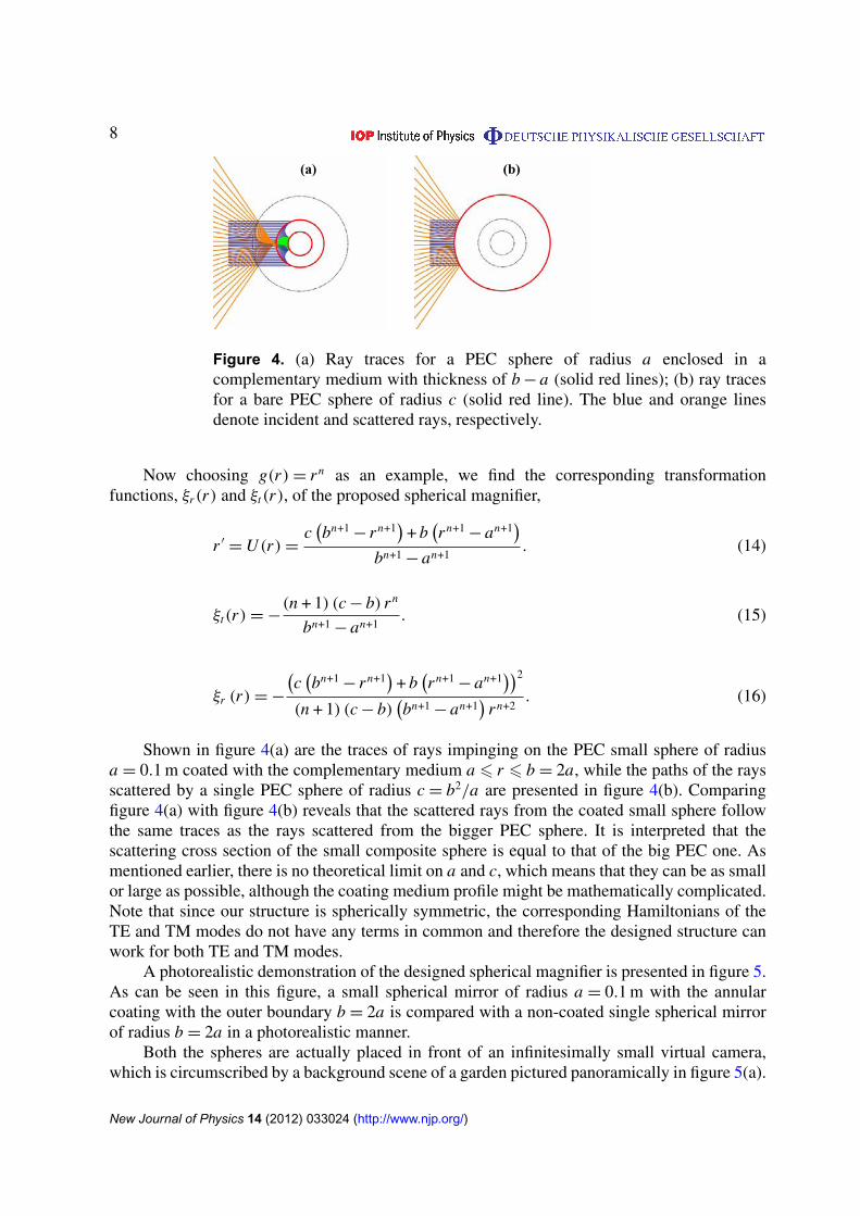
Figure 4. (a) Ray traces for a PEC sphere of radius a enclosed in acomplementary medium with thickness of b − a (solid red lines); (b) ray tracesfor a bare PEC sphere of radius c (solid red line). The blue and orange linesdenote incident and scattered rays, respectively.
Now choosing g(r) = r n as an example, we find the corresponding transformationfunctions, ξr(r) and ξt(r), of the proposed spherical magnifier,
r ′= U (r) =
c(bn+1
− r n+1)
+ b(r n+1
− an+1)
bn+1 − an+1. (14)
ξt(r) = −(n + 1) (c − b) r n
bn+1 − an+1. (15)
ξr (r) = −
(c(bn+1
− r n+1)
+ b(r n+1
− an+1))2
(n + 1) (c − b)(bn+1 − an+1
)r n+2
. (16)
Shown in figure 4(a) are the traces of rays impinging on the PEC small sphere of radiusa = 0.1 m coated with the complementary medium a 6 r 6 b = 2a, while the paths of the raysscattered by a single PEC sphere of radius c = b2/a are presented in figure 4(b). Comparingfigure 4(a) with figure 4(b) reveals that the scattered rays from the coated small sphere followthe same traces as the rays scattered from the bigger PEC sphere. It is interpreted that thescattering cross section of the small composite sphere is equal to that of the big PEC one. Asmentioned earlier, there is no theoretical limit on a and c, which means that they can be as smallor large as possible, although the coating medium profile might be mathematically complicated.Note that since our structure is spherically symmetric, the corresponding Hamiltonians of theTE and TM modes do not have any terms in common and therefore the designed structure canwork for both TE and TM modes.
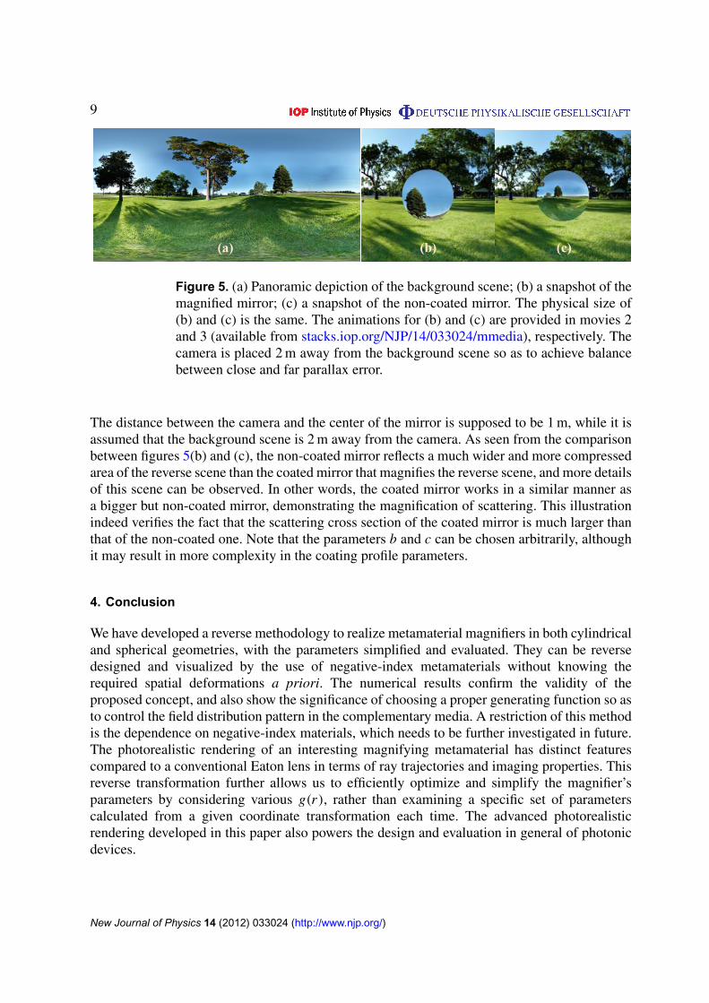
A photorealistic demonstration of the designed spherical magnifier is presented in figure 5.As can be seen in this figure, a small spherical mirror of radius a = 0.1 m with the annularcoating with the outer boundary b = 2a is compared with a non-coated single spherical mirrorof radius b = 2a in a photorealistic manner.
Both the spheres are actually placed in front of an infinitesimally small virtual camera,which is circumscribed by a background scene of a garden pictured panoramically in figure 5(a).
New Journal of Physics 14 (2012) 033024 (http://www.njp.org/)
9
)b()a( (c)
Figure 5. (a) Panoramic depiction of the background scene; (b) a snapshot of themagnified mirror; (c) a snapshot of the non-coated mirror. The physical size of(b) and (c) is the same. The animations for (b) and (c) are provided in movies 2and 3 (available from stacks.iop.org/NJP/14/033024/mmedia), respectively. Thecamera is placed 2 m away from the background scene so as to achieve balancebetween close and far parallax error.
The distance between the camera and the center of the mirror is supposed to be 1 m, while it isassumed that the background scene is 2 m away from the camera. As seen from the comparisonbetween figures 5(b) and (c), the non-coated mirror reflects a much wider and more compressedarea of the reverse scene than the coated mirror that magnifies the reverse scene, and more detailsof this scene can be observed. In other words, the coated mirror works in a similar manner asa bigger but non-coated mirror, demonstrating the magnification of scattering. This illustrationindeed verifies the fact that the scattering cross section of the coated mirror is much larger thanthat of the non-coated one. Note that the parameters b and c can be chosen arbitrarily, althoughit may result in more complexity in the coating profile parameters.
4. Conclusion
We have developed a reverse methodology to realize metamaterial magnifiers in both cylindricaland spherical geometries, with the parameters simplified and evaluated. They can be reversedesigned and visualized by the use of negative-index metamaterials without knowing therequired spatial deformations a priori. The numerical results confirm the validity of theproposed concept, and also show the significance of choosing a proper generating function so asto control the field distribution pattern in the complementary media. A restriction of this methodis the dependence on negative-index materials, which needs to be further investigated in future.The photorealistic rendering of an interesting magnifying metamaterial has distinct featurescompared to a conventional Eaton lens in terms of ray trajectories and imaging properties. Thisreverse transformation further allows us to efficiently optimize and simplify the magnifier’sparameters by considering various g(r), rather than examining a specific set of parameterscalculated from a given coordinate transformation each time. The advanced photorealisticrendering developed in this paper also powers the design and evaluation in general of photonicdevices.
New Journal of Physics 14 (2012) 033024 (http://www.njp.org/)

10
Acknowledgments
The authors are grateful to the Temasek Defence System Institute for support through the projectTDSI/11-004/1A.
References
[1] Leonhardt U 2006 Science 312 1777[2] Pendry J B, Schurig D and Smith D R 2006 Science 312 1780[3] Alitalo P and Tretyakov S 2009 Mater. Today 12 22[4] Schurig D, Mock J J, Justice B J, Cummer S A, Pendry J, Starr A F and Smith D R 2006 Science 314 977[5] Cai W S, Chettiar U K, Kildishev A V and Shalaev V M 2007 Nature Photonics 1 224[6] Liu R, Ji C, Mock J J, Chin J Y, Cui T J and Smith D R 2009 Science 323 366–9[7] Lai Y, Chen H Y, Zhang Z Q and Chan C T 2009 Phys. Rev. Lett. 102 093901[8] Yang T, Chen H Y, Luo X and Ma H 2008 Opt. Express 16 18545
Luo Y, Zhang J, Chen H, Wu B I and Ran L X 2009 Prog. Electromagnetics Res. 95 167[9] Rahm M, Cummer S A, Schurig D, Pendry J B and Smith D R 2008 Phys. Rev. Lett. 100 063903
[10] Han T, Qiu C W and Hong X 2011 Opt. Lett. 36 181[11] Kildishev A V and Shalaev V M 2008 Opt. Lett. 33 43[12] Chen H Y, Chan C T and Sheng P 2010 Nature Mater. 9 387[13] Wee W H and Pendry J B 2009 New J. Phys. 11 073033[14] Chao L, Meng X, Liu X, Li F, Fang G, Chen H Y and Chan C T 2010 Phys. Rev. Lett. 105 233906[15] Zhang B and Barbastathis G 2010 Opt. Express 18 11216[16] Hashemi H, Zhang B, Joannopoulos J D and Johnson S G 2010 Phys. Rev. Lett. 104 253903[17] Zhang B, Luo Y, Liu X and Barbastathis G 2011 Phys. Rev. Lett. 106 033901
Chen X, Luo Y, Zhang J, Jiang K, Pendry J B and Zhang S 2011 Nature Commun. 2 176[18] Halimeh J C, Schmied R and Wegener M 2011 Opt. Express 19 6078[19] Ma Y, Ong C K, Tyc T and Leonhardt U 2009 Nature Mater. 8 639
New Journal of Physics 14 (2012) 033024 (http://www.njp.org/)