PHOTOELECTRIC TRISTIMULUS COLORIMETRY WITH THREE … · 2 CircularsoftheNationalBureauofStandards...
54
M-7'* U. S. DEPARTMENT OF COMMERCE NATIONAL BUREAU OF STANDARDS PHOTOELECTRIC TRISTIMULUS COLORIMETRY WITH THREE FILTERS CIRCULAR C429
Transcript of PHOTOELECTRIC TRISTIMULUS COLORIMETRY WITH THREE … · 2 CircularsoftheNationalBureauofStandards...

M-7'*
U. S. DEPARTMENT OF COMMERCENATIONAL BUREAU OF STANDARDS
PHOTOELECTRIC TRISTIMULUS
COLORIMETRY
WITH THREE FILTERS
CIRCULAR C429

National Bureau of Standards
SEP 3 1947
(o \&10
?h
7^2 I£ U
ovj
• *0 1
cv G ft-4” 0 O •o— -—
*
Pi •— UA^HH >5 t>» ft<^ t>> >4- i»0 <—
1
Pi rH 4H O 0O ~ 0 P 0 0 O © 0 0
a 0 0 P 0 P 0 rH P p0 CO rH 0 € 0 O 0 •» 00 t>> 0 Pi •rH G 0 ~ G G Pi
PQ X| 0 0 G 0 G 0 0 O 0Ph u ft 0 ft 0 t>5 ft 0 ft
0 © 0 JG 0 x| O © 0 0> •• •• P 0 O 0 O 0 0 O 00 0 Pi 0 o 0 0 GW
|0 0 £3 0 0 Pi 0
t£) © 0 0 0 O 00 r~i JH rH 0 G •• 0 G o GPi o 0 0 O O 0 G O O0 t> X> P 0 5>> •H G 00 0 0
i—
1 G G 0 G • 0 0 0 G 03 0 ©00 PCM 03 X| 0 0 3 0O 0 VitJ (D 0-t0 P 0 © O 0JH0 <0 O £ O O O 0 O Pi o0 EH 0 0 O •H rH O P O C*D OO Ph O 0 Pi 0 0 0 0 G 0
S 0 G ^ ©W) O 'd 030 i—
1
0 0 0 0 0 0a jh G © G O Pi G 0 G G G0 p«H 0 0 0 0 0 P O 0 i3 0P W PiO 0 Fh ^ d • • 3 0 0 0 0 •• rtf
0 0 © © G 0 0 G XI 0 G G G0 +3 d ftd © 3 G0 3 0 3O P GOO -P 0 O © P O *50 OPh 0 O *hCQ 0 JG pQ > G PQ O PQ
CO ft— PQ P— pq ©— hH—0 oXj 1 1 1 i
E-H
c*\ O o- o0“
-4-
• • • •
O O O O525 5z; S25 M

11”'

U. S. DEPARTMENT OF COMMERCEJESSE H. JONES, Secretary
NATIONAL BUREAU OF STANDARDSLYMAN J. BRIGGS, Director
CIRCULAR OF THE NATIONAL BUREAU OF STANDARDS C429
PHOTOELECTRIC TRISTIMULUS
COLORIMETRY WITH THREE FILTERS
By
RICHARD S. HUNTER
[Issued July 30, 1942]
UNITED STATES
GOVERNMENT PRINTING OFFICE
WASHINGTON : 1942
For sale by the Superintendent of Documents, Washington, D. C. Price 10 cents

PREFACE
The photoelectric cell is finding ever-widening usage in scientific
apparatus. The present Circular describes the development and use
of an “ artificial eye for color measurement”, which consists of a barrier-
layer photocell and three selected spectral filters. The distinguishing
feature of a photoelectric tristimulus colorimeter is the approximate
spectral equivalence of the filter-photocell combinations of the appa-
ratus and the tristimulus specifications of the spectrum which char-
acterize the color vision of the average normal observer. Because of
this approximate equivalence, the new apparatus will respond to color
differences in much the same manner as the normal human eye.
Excepting cases in which the present lack of ideal spectral equivalence
introduces errors which cannot be tolerated, the photoelectric tristi-
mulus colorimeter described herein can be used to measure both the
size and the character of color differences. The potential speed and
relative simplicity of the apparatus suggest its use in quantitative
studies of color tolerance. Whenever suitable color standards are
available, the same advantages recommend the use of the apparatus
for tests of materials for compliance with color specifications.
Lyman J. Briggs, Director.
ii

PHOTOELECTRIC TRISTIMULUS COLORIMETRY WITHTHREE FILTERS 1
By Richard S. Hunter
ABSTRACT
The term “Photoelectric colorimetry” is commonly employed to designateboth photoelectric tristimulus colorimetry, used to evaluate the appearance ofmaterials, and abridged spectrophotometry, often used to assist in chemicalanalyses. This paper is devoted to the first type of measurement.
For a photoelectric tristimulus colorimeter, it is desired to find three or moresource-filter-photocell combinations of such spectral character that they duplicatethe standard ICI observer for colorimetry. With an instrument having thesecombinations, tristimulus values would be obtained by direct measurement.Although no one has duplicated the ICI observer perfectly, several investigatorshave obtained source-filter-photocell combinations suitable for the measurementof color differences between spectrally similar samples.To measure color differences as small as those which the trained inspectors of
paint, textile, plastic, paper, and ceramic products can see, an instrument musthave high precision. If the needed precision is available, a photoelectric tristim-ulus colorimeter may be used to measure: (1) ICI colorimetric values, x, y, andY, relative to those of a spectrally similar, calibrated standard
; (2) relative valuesof a and /S, components of the ehromaticity departure from neutral in a newuniform-chromaticness-scale mixture diagram for representing surface colors;
(3) amounts of color difference between pairs of spectrally similar samples;(41 amounts of color change accompanying fading; and (5) whiteness of whiteand near-white surfaces.
In giving examples of the measurement of some of these different propertiesand in describing the errors of color mesaurement to which the tristimulus methodis subject, reference is made to operations with the author’s recently developedmultipurpose photoelectric reflectometer.
CONTENTSPage
Preface nI. Introduction 2
II. Terms, symbols, and definitions 41. Physical 42. Psychological 53. Psychophysical 5
III. The source-filter-photocell combinations 6IY. Reduction of photoelectric tristimulus data 10
1. To ICI values, x, y, and Y 122. To (a, p) -uniform-chromaticness-scale coordinates 143. To the amount of perceived color difference, AE, between two
surface colors 164. To the coordinates, a
,/S', L', of a solid with an approximately
uniform color-perception spacing 195. To the hue angle, </>, the saturation index, S
,and the lightness
index, L 206. To estimates in NBS units of the hue, saturation, and lightness
components, AH', AS', and AL',of a perceived surface-colordifference 20
7. To whiteness, W 218. To yellowness 22
1 A preliminary brief account of this project was presented as part of the ASTM-ISCC joint Symposiumon Color held in Washington, March 5, 1941 [19].
1

2 Circulars of the National Bureau of Standards
PageV. Standards for photoelectric tristimulus colorimetry 22
VI. Errors in photoelectric tristimulus measurements 241. Errors in tristimulus measurements of chromaticity difference
due to spectral inaccuracy of the source-filter-photocellcombinations 25
2. Changes in measured chromaticity resulting from change ofphotocell in an instrument 28
3. Fluorescence errors 304. Short cuts in computation which produce only small errors 31
(a) Omitting scale corrections 31(b) Neglect of the difference between the known A, G
,
and B values for the standard and the approxi-mate values read directly from the instrument 31
(c) Using 0.5 and 0.1 instead of the accurate values forthe neutral-filter transmission factors 32
(d) Amounts of error from using short-cut methods 33VII. The relation of perceptual impressions and measured values of color__ 34
VIII. Examples 35IX. Summary 43X. References 44
I. INTRODUCTIONThe possibility of using photocells to measure color has attracted
widespread attention ever since the photoelectric cell became avail-
able in practical form. Photoelectric cells have now been used for anumber of years in spectrophotometry to measure the spectral reflec-
tive and transmissive properties of materials. From the spectro-photometric curves of samples, one may obtain the tristimulus valuesof color by multiplying the separate spectral values of any sample bythe three distribution functions of the standard observer 2 and totaling
the three sets of products throughout the visible spectrum (see eq. 3,
below). Although the use of photocells has considerably diminishedthe time needed to obtain spectrophotometric curves, and althoughdevices such as the one developed by Sears [43]
3 are available to
facilitate the integration, a considerable expenditure of time andeffort is still required [29 p. 259] to obtain the accurate colorimetricspecification of a sample by the method of spectrophotometry andintegration.
Photoelectric tristimulus colorimetry is direct and rapid, becausethe result of integration with respect to wavelength is found automa-tically by the use of specially chosen source-filter-photocell combina-tions (see eq. 5, below). With this type of photoelectric colorimeter,
the tristimulus specification of a sample is found by settings upon it
using in succession each of the three or more filters in an instrument.This direct method of color measurement has at present somewhatlimited application, because the best available source-filter-photocell
combinations fail to be spectrally equivalent to the desired combina-tion of the ICI standard observer and standard illuminant for colo-
rimetry. Nevertheless there are many problems of color measurementto which the shorter procedure may be advantageously applied, andthese will doubtless increase in number as research progresses.
Photoelectric tristimulus colorimetry is frequently confused withphotoelectric abridged spectrophotometry [11], and both are popu-larly called photoelectric colorimetry. Therefore, a short discussion
For descriptions of the ICI standard observer for colorimetry, see references [15, 20, 22, 25, 31, 33 and 45].3 Numbers in brackets, either with or without specific page numbers, indicate references listed at the end
of this Circular.

Photoelectric Tristimulus Colorimetry 3
of the two experimental methods and of the differences between themis appropriate. Instruments for both procedures require a source,several filters, and a photocell. Instead of the prism or grating usedin a true spectrophotometer, three to about eight spectral filters areused in an abridged spectrophotometer to isolate spectral bands.These bands are of wider wavelength ranges and are fewer in numberthan the bands employed in true spectrophotometry, consequentlyaccurate spectrophotometric curves are not obtained [21]. Never-theless, an abridged spectrophotometer is often a useful instrument.Frequently, it is known that some particular chemical or physicalproperty of a substance may be studied by using a single spectralrange or several spectral ranges which may be isolated by filters. Anabridged spectrophotometer may serve adequately for the measure-ments needed.A tristimulus colorimeter also requires filters, but it does not pri-
marily measure the variation of any property of samples with respectto wavelength. Instead samples are measured with source-filter-
photocell combinations which spectrally duplicate, as nearly as pos-sible, the three distribution functions characterizing the standardobserver combined with some standard illuminant. With one sourceand photocell, three or at most four filters are needed. However,the filters for tristimulus colorimetry differ from those used for
abridged spectrophotometry in that they transmit bands of widewavelength range.
Ives described a thermopile tristimulus colorimeter in 1915 [23],
which made use of a spectrum selectively projected through a series
of carefully cut templates in place of the filters employed in the morerecent devices. Twyman and Perry showed in 1928 [46] that aninstrument which would yield direct tristimulus measurements couldbe obtained by finding source-filter-photocell combinations spectrally
similar 4 to the standard-observer, illuminant combination for col-
orimetry. 5 However, it was not until 1938 that Perry described anactual instrument for photoelectric tristimulus colorimetry. Hecalled his device the Blancometer [40] because of its special suita-
bility for white and near-white samples. Guild described the experi-
mental model of a tristimulus colorimeter in 1934 [14], and Winch andPalmer [50], Dresler and Fruhling [4], and Barnes [2], have described
devices for the same purpose since that time. Gibson [11] and Vanden Akker [47] have discussed the problem of obtaining the source-
filter-photocell combinations giving the closest spectral equivalence
to the standard observer.
The present paper describes a three-filter method for approximatephotoelectric tristimulus colorimetry which has so far been used
chiefly in conjunction with the author’s multipurpose reflectometer
[18] to measure surface color. Tristimulus measurements with this
instrument have proved to be valuable in studies of the colors of paints,
ceramic products, textiles, papers, pigments, inks and other materials
which reflect light. The major part of the present paper is devoted
4 For a discussion of what is meant by spectrally similar, see footnote 7.5 The three ideal source-filter-photocell combinations would each duplicate in spectral response the relative
spectral distribution of one of the three functions of the ICI standard observer combined with chosen stand-
ard illuminant (as expressed in eq 1, below). A standard illuminant is, in general, relatively nonselective
and plays a secondary role in determining the spectral character of the ideal source-filter-photocell combina-
tions. In the remainder of the paper it has sometimes been convenient to speak of spectral duplication
of, or spectral simil arity to the standard observer when actually spectral duplication of, or spectral similarity
to, the standard observer combined with a standard illuminant is meant.

4 Circulars of the National Bureau of Standards
to tristimulus measurements of surface colors, but it should be notedthat a number of the methods suggested are equally useful for thestudy of volume colors by measurements of transmitted energy andfor the study of illuminant colors by measurements of emitted energy.
II. TERMS, SYMBOLS, AND DEFINITIONS
It is the purpose of photoelectric tristimulus colorimetry to giveby measurement quantities which provide useful information aboutthe appearance of objects and lights. Three different classes of
properties must be recognized in the study of the subject: physical,psychological, and psychophysical. Physical properties have nonecessary connection with an observer; psychological properties dealdirectly with the impressions of an observer and are therefore notsubject to exact physical measurement; psychophysical propertiesare an intermediate class which are capable of measurement, but whichrelate to the impressions of an observer. It is important to dis-
tinguish between these three classes of properties and identify theterms which refer to each.
To assist in this differentiation, table 1, which classifies a numberof the terms used herein, has been prepared. This table is modeledafter figure 1 in the Preliminary Draft of a Report on Nomenclatureand Definitions for Colorimetry [24] by L. A. Jones, chairman of theColorimetry Committee of the Optical Society of America. Oneterm in table 1, chromaticness, has been added to accord with thepresent draft of the uncompleted report of this committee.
Table 1 .—Tabular arrangement of some of the terms used to describethe color of a surface
Category Physical -Psychophysical (Physically measured,
psychologically significant).Psychological.
Instrument Spectrophotometer. Tristimulus colorimeter Visual mechanismof the observer.
Product of the in-
strument.Spectral apparent-reflectance curve.
Designation of the surface color by a set oftristimulus values for it; X, Y, and Z;A, G, and B; or other.
The perceived sur-face color.
The separate at-
tributes of the sur-face color, and theperceived surfacecolor.
'(1) Luminous apparent reflectance, Aoi,«c (chiefly designated below by Y).the lightness index, L.
(2) Dominant wavelength, A, or hueangle, <t>.
' (3) Purity, p, or saturation index, S
(2 and 3 combined) Chromaticity, indi-
cated either by A and p, <f> and S, or bya pair of tri-linear coordinates, x and y,
,
a and (), etc.
(1) Lightness.
(2) Hue.
(3) Saturation, or“strength.”
(2 and 3 combined)Chromaticness.
The definitions, and in some cases symbols, for a number of theterms used in the present paper are separated below according to thethree categories.
1. PHYSICAL
A spectrophotometer is an instrument which measures transmission
or apparent reflectance as a function of wavelength.A spectrophotometric curve is a curve giving transmission, T\, or
apparent reflectance, A\, of a sample as a function of wavelength.

Photoelectric Tristimulus Colorimetry 5
2. PSYCHOLOGICAL
A perceived surface color is color experienced as a property of asurface [30] ;
the three attributes of a perceived surface color are light-
ness, hue, and saturation.
The lightness of a perceived surface color is that attribute whichpermits it to be classed as equivalent to some member of the series ofgrays ranging from black to white [30]. (In the Munsell system,value correlates closely with lightness under usual observing condi-tions.)
The hue of a perceived color is that attribute which permits it to
be classed as red, yellow, green, blue, purple, or an intermediate [30].
Chromatic surfaces are those perceived to possess hue (not to beconfused with Munsell chroma) [30].
Achromatic surfaces are those such as whites, grays, and blackswhich are perceived to possess no hue [30].
Saturation is that attribute of a perceived surface color whichdetermines the degree of its difference from the gray of the samelightness [30]. (Munsell chroma correlates closely with saturationunder usual visual conditions.)
The chromaticness of a perceived color is determined by its hue andsaturation taken together.
3. PSYCHOPHYSICAL
A tristimulus colorimeter is a device which measures a color stimulusin terms of three selected stimuli called primaries. The ideal source-filter-photocell combinations for a photoelectric tristimulus colorimeterare those which are spectrally equivalent to the 1931 ICI standardobserver for colorimetry in combination with an appropriate illuminant.
The 1931 ICI standard observer for colorimetry embodies the averagecolorimetric characteristics of 17 normal observers studied by Guild
[13] and Wright [51]. The definition of the standard observer consists
of three functions of wavelength, X, showing the relative amounts(zx , y\, z\) of three primary stimuli required to color-match the variousparts of the equal-energy spectrum [15, 22, 25, 31, 33, 45].
A tristimulus designation of an unknown stimulus consists of theamounts (such as X, Y, Z) 6 of the three primary stimuli required to
produce a color match for it.
Apparent reflectance is the reflectance which a perfectly diffusing
surface would need to have in order to produce, under the same angularconditions of illuminating and viewing, the same instrumental effect
as the specimen actually measured. Apparent reflectance given as afunction of wavelength is designated spectral apparent reflectance,
A\ (ei,ev), and is most frequently represented by a spectrophotometriccurve. Apparent reflectance weighted according to the luminosityfunction is designated luminous apparent reflectance, A {ei,e V), or Y.
For apparent-reflectance values weighted according to other spectral
functions, such as those of the source-filter-photocell combinationsdescribed below, symbols which identify the functions are used.
The Y component of the tristimulus designation of a color repre-
6 It should be noted that there has not been universal agreement on the use of these symbols. TheNational Bureau of Standards has in the past usually usedi, y, and z to represent the tristimulus designationof an unknown stimulus and X
,Y, and Z to represent the trichromatic coefficients of the spectrum. In the
present paper, however, this former use of symbols has been discarded in favor of the above usage, which is
recommended in the present unpublished draft of the OSA Colorimetry Committee report.

6 Circulars of the National Bureau of Standards
sents the luminous component of that color [31, 33]. Thus Y desig-
nates the luminous apparent reflectance of a surface color, the luminoustransmission of a volume color, and the brightness of an aperture or
illuminant color. The methods of measurement described below are
in most cases applicable to problems involving volume, aperture, andilluminant colors as well as to the surface colors referred to in the text.
For this reason, the symbol Y has been used below instead of Aoi,ev
where the text refers to luminous apparent reflectance. It should benoted that the symbol A is used herein to designate settings with themultipurpose reflectometer and amber filter.
The settings,A, G, and B, with the multipurpose reflectometer
employing, respectively, the amber, green, and blue filters, are, for asurface color, apparent reflectances for illumination at 45° and viewingat 0° relative to MgO. In practice the instrument is adjusted by meansof a working standard calibrated in terms of MgO. Illumination at45° and viewing at 0° have been internationally adopted as standardconditions for the colorimetry of opaque surfaces [22], because theyrepresent a satisfactory average of the directional conditions underwhich surfaces are observed in everyday life. Because the combina-tion of source, green filter, and photocell nearly duplicates the stand-ard luminosity (y) function times ICI illuminant C, readings obtainedwith the green-filter combination closely duplicate Y. Because thethree source-filter-photocell combinations are nearly equivalentspectrally 7 to the ICI standard observer, measurements of A, G, andB of a sample constitute an approximate tristimulus description of its
color.
The chromaticity of a color is its characterization by either (1)
dominant wave length and purity, (2) hue angle and saturation index,
or (3) a pair of trilinear coordinates (x and y, a and 0, etc.).
The dominant wavelength,A [41], and the hue angle
, <£, of a color are
both computed from the tristimulus specification to indicate hue.The purity
, £>[41], and the saturation index,S, of a color are obtained
from the tristimulus specification to indicate what is variously called
saturation or strength.
The trilinear coordinates (x , y, and z, or a, j3, and 7) are the amountsof the three primary stimuli expressed as fractions of their total.
Because the three trilinear coordinates of a color are fractions of atotal and must necessarily sum to unity, two of them (either x and y,or a and /S) are sufficient to define the chromaticity of a stimulus.
A chromaticity diagram is a plot according to trilinear coordinates in
which position of a point indicates the chromaticity of the stimulusrepresented.
III. THE SOURCE-FILTER-PHOTOCELL COMBINATIONS
The distinguishing feature of apparatus for photoelectric tristimulus
colorimetry is that spectral elements nearly equivalent to the ICIstandard observer for colorimetry must be provided. If the device
is to be used for the colorimetry of light sources, television screens, or
other self-luminous color stimuli, the apparatus will require filters
and photocells only. If the samples are to be non-self-luminous
7 By “nearly equivalent spectrally to the ICI standard observer” is meant that the spectral distributionsof the three source-filter-photocell combinations can he changed by transformation equations which arelinear and homogeneous [31, p. 345] to spectral functions which nearly duplicate the ICI standard observercombined with illuminant C (see figure 1, below).

Photoelectric Tristimulus Colorimetry 7
objects, such as opaque surfaces or transparent media, a source for
illuminating the objects must be added to the filter-photocell com-binations. The resulting sets of source, filter, and photocell mustthen be nearly equivalent in spectral response to the standard observercombined with the desired standard illuminant.
The combinations of elements described in the present paper are
those which have been used for tristimulus colorimetry with theauthor’s multipurpose reflectometer [18]. Although used for the mostpart in this one instrument, the source-filter-photocell combinationsdescribed below are applicable to photoelectric tristimulus colorimetrywith other photoelectric devices 8 of suitable precision.
If the three spectral response functions of the ICI observer aredenoted by x, y, and z and the spectral energy of the illuminant for
equivalent visual analysis is denoted by Ev ,then the ideal source-
filter-photocell combinations for photoelectric colorimetry accordingto the ICI observer will satisfy the following equations:
( 1 )
The source in the instrument is represented by its spectral energy,Ej
}the ideal filters by their spectral transmissions, Tx ,
T2 ,and Tz ,
thephotocell by its spectral response, s, and the constants of proportion-ality between the two sides of the respective equations by Kh K2 ,
and Ks .
An instrument was desired which would give numbers correspond-ing to those furnished by the ICI observer rating objects under ICIilluminant C 122],
9 a standard illuminant which is similar in spectral
quality to overcast sky. Accordingly Ec representing ICI illuminantC, was substituted for Ev in eq 1. Since a source of high efficiency
and small area is needed in the apparatus, a Mazda projection-typeincandescent lamp was chosen. This is operated at approximately3,100° K, and hence the relative spectral irradiance corresponding to
3,100° K [44] was used for ET . The General Electric light-sensitive
cell [10] was chosen because 10 of the high current it generates for agiven illumination and the relatively high response to light of the blueregion of the spectrum, and because data giving the spectral responseof the cells available for the author’s instrument were at hand. 11
It was recognized that ideal filters satisfying eq 1 would not befound. No attempt was made to duplicate with a single source-filter-
photocell combination the complete x function with its two com-ponents. Instead, the two components were separated as suggestedby Gibson [11], and the short-wave component was taken to bespectrally similar to the z function. 12 A combintion was then sought
8 These combinations, for example, have been used in the Lumetron Colorimeter, Photovolt Corporation,95 Madison Avenue, New York, N. Y.
6 By using one of the color-temperature altering filters described by Gage [9] or Estey [5] with each of thethree source-filter-photocell combinations, it is possible to obtain the effect of raising or of lowering the colortemperature of Ev . Thus it is possible to simulate not only visual observations made under ICI illuminantC, but visual observations made under light from a yellow incandescent lamp, or from blue sky.
10 For a more detailed account of the selection of the photocells used for tristimulus colorimetry in. themultipurpose reflectometer, see [18, p. 584, and 18a, p. 538].
11 Kindly supplied by B. T. Barnes, of the General Electric Co., Nela Park, Cleveland, Ohio.1 2 Guild [14], Perry [40], Dresler and Friihling [4], Barnes [2], and Van den Akker [47] have all pointed
out that a fourth source-filter-photocell combination is preferable to using the z combination in order tosimulate suitably the short-wave component of the x function. However, the author is chiefly interested in
the measurement of small differences in color with the simplest procedures possible. If three filters will
suffice, a fourth adds undue complexity to the measurements. Until important improvements are madein the degree to which the three present filters duplicate the ICI observer, the use of a fourth filter is
unwarranted.
462854°—42 2

8 Circulars of the National Bureau of Stavidards
to duplicate the long-wave component only. This component of thexEc function is approximated by using an amber filter having a spectral
transmission, TA . The yEc and zEc functions are approximated byusing green (T0) and blue (TB) filters, respectively.
Table 2.—Spectral character of the individual components and of the source-filter-
photocell combinations used for photoelectric tristimulus colorimetry with the
multipurpose reflectometer [75]
Wave-length
Spectral transmissions(Corning filters)
Ei, relativespectral
irradianceof source
at 3,100° K[44]
s, spectralresponse
of GE cell
No. 55 (in
micro-amperesper milli-
watt)
Spectral specification of the threesource-filter-photocell combina-tions. (Each value of k hasbeen chosen so that the sum of
the column is 100,000.)
Ta, amberfilter of
No. 330yellow
glass andNo. 978greenglass
To, greenfilter of
No. 428green
glass andNo. 330yellowglass
Tb, bluefilter ofNo. 554
blue glass
and No.038
yellowglass
EiTAskA(amber)
EjToska(green)
EiTBskB(blue)
my380 0.010 0.000 0. 1188 94.5 31
90 .010 .000 1425 101.5 39
400 .011 .000 1688 107.8 5610 .011 .020 1979 113.9 70 33720 .012 .298 . 2294 119. 5 92 6, 10930 .013 .443 . 2634 124. 7 120 10, 88540 .017 .478 . 2998 129. 7 185 13, 901
450 .023 .482 . 3383 134. 2 291 16, 36860 .035 .445 . 3790 138.8 514 17, 51170 .050 .338 . 4215 143.0 842 15, 23780 .077 .195 .4658 147.2 1, 476 10, 00190 0. 004 .107 .090 .5114 151.3 96 2, 315 5, 208
500 .010 .138 .045 .5582 155.5 269 3, 350 2,92210 .020 .173 .015 .6061 159.1 596 4, 664 1, 08220 .038 .209. .003 .6548 162.3 1,248 6, 210 23930 .063 .235 .000 .7040 164.9 2,258 7,62840 .095 .249 . 7536 167.0 3, 695 8, 763
550 .128 .251 .8033 168.4 5, 351 9,49660 . 164 .243 . 8531 168.7 7,291 9, 77870 . 196 .222 . 9025 167.4 9, 148 9, 37880 .224 . 193 . 9516 162.9 10, 727 8, 36690 .237 . 163 1. 0000 156. 3 11, 443 7, 125
600 .238 . 135 1. 0476 147. 5 11, 363 5, 83310 .227 . 109 1. 0945 135. 4 10, 393 4, 51620 .206 .086 1. 1403 117. 3 8, 511 3, 21630 . 181 .067 1. 1850 97. 7 6, 472 2, 17040 . 153 .053 1. 2284 79.1 4, 594 1,440
650 .122 .040 1. 2704 60.8 2,910 86460 .099 .032 1.3111 43.7 1, 752 51270 .077 .025 1. 3503 28.5 914 26880 .057 .020 .000 1. 3880 18.0 439 14090 .043 .017 .002 1. 4240 11.9 226 81 25
700 .030 .014 .003 1. 4584 8.8 117 50 2810 .022 .012 .004 1. 4912 7.2 74 36 3220 .016 .010 004 1. 5223 6.1 46 25 2830 .011 .009 .005 1. 5517 5.8 31 22 3440 .008 .008 .004 1. 5793 5.7 22 20 27
750 .005 .007 .004 1. 6055 5.5 12 17 26
2 99, 998 99, 999 100, 000
Spectral specifications for the source-filter-photocell combinationschosen, EzTAskA , E^oska, and EzTBskB ,
are given in table 2. Includedin the same table are the spectral transmissions of the three filters,
13
13 The author is indebted to H. J. Keegan, of this Bureau, for numerous spectral-transmission curvesobtained during the course of this work.

Photoelectric Tristimulus Colorimetry 9
the spectral irradiance from a source at 3,100° K., and the spectralresponse of GE light-sensitive cell No. 55. The values of k were ad-justed so that each of the final three columns would total 100,000.Each filter consists of two components, all six components chosen beingfrom stock manufactured by the Corning Glass Works. 14
The success with which the source-filter-photocell combinationsduplicate the ICI standard observer combinedjvith illuminant C is
shown graphically in figure 1, in which xEc ,yEc,
and ~zEc ,which
Figure 1 .—The ICI observer, represented by the curves xEc ,
yEc ,and zEc, com-
pared to its approximate duplication by the source-filter-photocell combinationsused in the multipurpose reflectometer.
enclose areas of approximately 98,000, 100,000, and 118,000, respec-tively, are plotted as functions of wavelength together with
0 .80ETTAskA +0.18EZTBskB ,
and1 .OOE^Tosk^,
1.18EjTBskB ,
which enclose respectively equal areas. The duplication is far fromperfect and can be improved by further work. Also, as already noted,
14 It is possible to obtain suitable tristimulus filters from Coming glass available at the present writing(October 1941), by using the following designations and thicknesses:
Component Catalognumber
Melt desig-
nationThickness
Yellow component of amber filter, 326 190mm2.42
Green component of amber filter, , 978 *£mo=0. 338 1.3
Blue-green component of green filter 428 194 3.65Yellow component of green filter 330 17 3.30
Blue component of blue filter 554 211 5.00Yellow component of blue filter . 038 206 1.5
•This Coming & value bears no relation to the trilinear coordinate 0.

10 Circulars of the National Bureau of Standards
the use of a fourth filter would improve the duplication. The follow-
ing approximate equations designate the relationships shown in
figure 1 and serve as the basis for comparison of ICI tristimulus valuesand photoelectric tristimulus values:
xEc = 0 .802?/TAskA -f- 0 . 1SETTbsJcb'
yEc = 1 .00E^oska
1EC= 1 . 1 8£!rTBskB .
(2)lp
IV. REDUCTION OF PHOTOELECTRIC TRISTIMULUSDATA
Values of A, G, and B obtained from a photoelectric tristimulus
colorimeter may be converted to useful information about the colors
of the samples measured in a number of different ways. Each pro-cedure for reducing data gives numbers which are useful for a particular
purpose. In table 3 the quantities which can be computed are identi-
fied by the equations for finding them and by their principal uses.
As previously noted, the methods of measurement suggested hereinrefer chiefly to surface colors. It is believed, however, that several
of these suggested methods will prove to be equally applicable to theevaluation of volume colors from transmission measurements and to
the evaluation of the colors of self-luminous objects from measure-ments of radiant flux.
15 The author is indebted to Miss N. J. Hendley (now Mrs. E. M. Furness) for assistance in finding trans-formations of the source-filter-photocell combinations which were closely equivalent to the standard observer.After experiment with several transformations giving slightly closer equivalence to the standard observer,it was decided that the simple transformations indicated by eq 2 were more practical for ordinary use.

Table
3.
—
Uses
of
photoelectric
tristimulus
Photoelectric Tristimulus Colorimetry 11

12 Circulars of the National Bureau of Standards
1. TO ICI VALUES, x, y, AND Y
The ICI standard system[22
]for designating colors has international
recognition and is therefore widely used in the specification of colors.
The tristimulus specification of a surface color according to the ICIobserver is the summation through the spectrum of the spectral appar-ent reflectance of the sample relative to MgO(4a
(
0 i.es) being meas-ured by a spectrophotometer), times the spectral energy, Ec ,
of theilluminant, times the respective spectral distribution functions, x, y,
and z of the ICI observer:
X= c
c
X=^2/A-\ (0i o V)EcxA\x=o
X=oc
Y=^LjA\ (ei'0 V)EcyA\x=o
X=oc
Z= )> 4-X
(
di,6v)EcZA\
.
X=0
(3)
If the same sample is compared with MgO in a photoelectric tristimulus
colorimeter, the following summations through the spectrum are
made automatically:x=^
l̂A\
(e i ,ev)EITAskAA\=Ax=o
X= Cg
)A\ (6i,6v )EjTGskGA\
x=o= G
^y2jA\(eitev)EiTB§k gAX —B
x=o
(4)
A, G, and B are, by definition, the settings of the sample relative to
those of standard MgO with the amber, green, and blue filters, respec-
tively.
By multiplying both sides of eq 2 by A\(g ite v >
and making summa-tions through the spectrum, we find by way of eq 3 and 4 that:
X=0.804+0.18£,'
1 .000,
Z= 1.1819.
(5)
The equations are only approximate, because the source-filter-photo-
cell combinations are spectrally somewhat different from the standardICI observer, as shown in figure 1 . However, photoelectric tristim-
ulus measurements according to a substitution method using acalibrated standard spectrally similar to the samples are, as is shownbelow, suitably accurate for many purposes.
Since the y function of the ICI observer is the luminosity function,
approximate values of luminous apparent reflectance are given directly
by settings with the green filter. To indicate chromaticity in theICI system, the trilinear coordinates of a color are computed as
follows:
x=x/(x+y+Z);
y= Y/(X+Y+Z),(6)

Photoelectric Tristimulus Colorimetry 13
Figure 2 shows the ICI (x,y)-diagram and the corresponding photo-electric approximation to the diagram plotted in the same coordinates.In each diagram are the spectrum locus and points representing 12differently colored porcelain-enamel plaques, 16 each illuminated by
Figure 2.
—
ICI (x,y)-diagram and corresponding photoelectric approximation to the
diagram with the point for white (MgO) common to both diagrams.
The pairs of points for the 11 chromatic porcelain-enameled plaques show the errors in chromaticitymeasured by the photoelectric tristimulus method. The small rectangle near the center gives boundariesshown in figure 7, below.
ICI illuminant C. The point z= 0.3 101 and 7/=0.3 163, representinga freshly prepared magnesium-oxide surface similarly illuminated is
common to both diagrams. Each of the twelve plaques was measuredrelative to MgO, first with a spectrophotometer and then with a multi-purpose reflectometer
;the values of x and y obtained from the two sets
of data were computed and plotted in figure 2.
18 The standards used are 10 kitchen and bathroom colors [36], and plaques representing medium chromeyellow [6] and international orange [7].

14 Circulars of the National Bureau of Standards
Coordinates of the spectrum locus of the ICI mixture diagram arepublished in many places [15, 22, 25, 31, 33, 45]; coordinates of theboundary of the photoelectric approximate chromaticity diagramwere computed by applying eq. 5 and 6 to the values of EzTAskA ,
ErTGskG and EjTssks given in table 2. At the ends of the visible
spectrum (380 to 420 mp and 670 to 750 m/x) the source-filter-photo-
cell combinations imperfectly duplicate the ICI standard observeras the distributions diminish to zero. Therefore the trilinear coordi-
nates which would result from photoelectric measurement of the spec-
Figure 3.— The (a,0)-uniform-chromaticness-scale diagram for surface colors
showing the spectrum locus and points representing ten Munsell colors of four-value and six-chroma [38], medium chrome yellow, international orange, and tol-
uidine red.
trum for these wavelengths of low response are highly inaccurate andhave been left out of figure 2.
2. TO (a, /3)-UNIFORM-CHROMATICNESS-SCALE COORDINATES
The (a , j8) -chromaticity diagram shown in figure 3 has been plannedespecially for representing surface colors measured with the multi-purpose reflectometer and tristimulus filters. Cartesian coordinatesand an origin located at the point representing MgO were used becauseof the greater convenience for plotting chromaticity, and because of
the simple relation afforded thereby between position of point in thediagram and saturation index and hue angle of the color represented.
The convenience of these two features was recognized by Breckenridgeand Schaub, who used them in then* earlier RUCS triangle [3]. In
Photoelectric Tristimulus Colorimetry 15
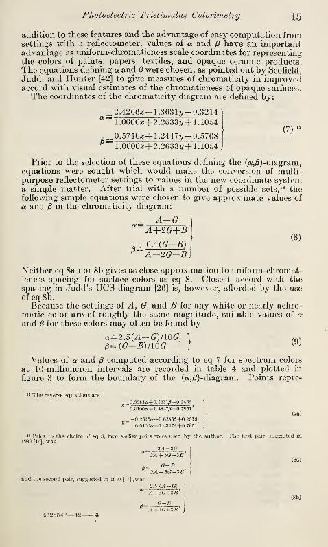
addition to these features and the advantage of easy computation fromsettings with a reflectometer, values of a and jS have an importantadvantage as uniform-chromaticness scale coordinates for representingthe colors of paints, papers, textiles, and opaque ceramic products.The equations defining a and (3 were chosen, as pointed out by Scofield,
Judd, and Hunter [42] to give measures of chromaticity in improvedaccord with visual estimates of the chromaticness of opaque surfaces.
The coordinates of the chromaticity diagram are defined by:
__ 2.4266a;— 1.3631?/— 0.3214“ 1.0000z+2.2633y+ 1.1054*
(7)17
0.5710z+1.2447?/-0.5708
1.00003+2.2633^+1.1054*,
Prior to the selection of these equations defining the (or,ft)-diagram,equations were sought which would make the conversion of multi-purpose reflectometer settings to values in the new coordinate systema simple matter. After trial with a number of possible sets, 18 thefollowing simple equations were chosen to give approximate values of
a and (3 in the chromaticity diagram:
A-G“ A+2G+B’\
OA(G-B)p A+2G+B]
Neither eq 8a nor 8b gives as close approximation to uniform-cliromat-icness spacing for surface colors as eq 8. Closest accord with thespacing in Judd’s UCS diagram [26] is, however, afforded by the useofeq8b.
Because the settings of +, G}and B for any white or nearly achro-
matic color are of roughly the same magnitude, suitable values of aand 0 for these colors may often be found by
a=2.5(A-G)/10G, 1
0= (G—B)/10G. J(9)
Values of a and /3 computed according to eq 7 for spectrum colors
at 10-millimicron intervals are recorded in table 4 and plotted in
figure 3 to form the boundary of the (a,&) -diagram. Points repre-
17 The reverse equations are
0 .5583a+0 . 1631/8+0.2466]
0.0100a- 1.4347/3+0.7951'(7a)
_ —0.2515a+0.62850+0.2515V
0.0100a- 1.43470+0.7951* j
18 Prior to the choice of eq 8, two earlier pairs were used by the author.1939 [16], was
_ 2A-2G]a
2A+5G+3B’
G-B'2++5G+3B*
and the second pair, suggested in 1940 [17] ,was
. 2.5 (A-G)A+6G+3B'
G-B
462854
*
++6G+3.B
The first pair, suggested in
(8a)
(8b)

16 Circulars of the National Bureau of Standards
senting three colors widely used on signs and markers have also beenplotted in figure 3. In addition, points have been plotted to showthe degree of agreement between the chromaticity scales of the newsystem and the chromaticness spacing of the Munsell system. UsingNickerson “smoothed” values of x and y for Munsell papers [381,
values of a and were computed by eq 7 for the 10 papers representingthe hues and intermediate hues of 4-value and 6-chroma under ICIilluminant C. The points representing these 10 papers would bespaced at equal intervals along the circumference of a circle if theMunsell system and the (a, fi)-diagram both gave perfectly uniformchromaticness spacings.
Table 4.—Values of a and /3, computed according to eq 7, of spectrum colors at1 0-millimicron intervals
Wavelength in millimicrons a. 0I
1
! Wavelength in millimicrons a 0
380 +0.0731+.0725
-0. 3604 550 —0. 1793 +0. 1557+. 1451
+. 1330+.1204+. 1082
90 -.3608 60 _. -.092470 +.0001
+. 0952+. 1879
400 +. 0718 -. 3612 8010 +. 0705
+. 0679+. 0613+.0484
-. 3617 90 .
20 -.362230 .. -. 3611 600 +. 2688
+. 3320+. 3754+. 4035+.4229
+.0974+. 0891+.0833+. 0796+. 0769
40 -. 3579 1020
450 +. 0265 -.3528 3060 -.0095 -. 3430 4070 -. 0729 -. 3146
80 -. 1876 — . 2361 650 +. 4352+.4423+. 4458+. 4483+. 4501
+.0753+. 0744+. 0740+. 0736+. 0734
90 -. 3373 -. 0977 6070
500 -.4440 +. 0446 80
10 -. 4651 +. 1317+. 1661
9020 -. 416630 -. 3387
-.2605+. 1688
+. 1641700 to \ +.4506 +. 0733
40 780 inelj~ ~
MgO under ICI illuminant C. .0000 .0000
Since the chromaticness spacing of the Munsell system is knownto be fairly good [37], the departure of the actual 10 points plotted in
figure 3 from equal spacing on the circumference of a circle can beconsidered a rough measure of the degree to which the (a
,$)-diagram
fails to give uniform chromaticness spacing of surface colors. Com-parison of the spacing of points in figure 3 with the similar spacingsof points representing Munsell papers in the {x,y)-diagram as shownby Newhall [37, p. 640] indicates a considerable advantage in favorof the (a,(3)-system.
3. TO THE AMOUNT OF PERCEIVED COLOR DIFFERENCE. AE,
BETWEEN TWO SURFACE COLORS
Expressions for estimating the amount of difference perceivedbetween two colors and for estimating the whiteness of a perceivedcolor have recently been set up by Judd [28, 29, 32]. Visual estimates
of these two properties are widely used in commerce, where it mustfrequently be decided whether the perceived color of one object is asuitable match for that of another, or whether a material meets awhiteness specification. By making minor changes in Judd’s twoexpressions, methods are available for rapidly converting photoelectric
tristimulus settings to values of AE and W which are in good accordwith perceived color difference and whiteness, respectively.

Photoelectric Tristimulus Colorimetry 17
To form his empirical equation for AjE, the approximate amount ofperceived color difference, Judd first assumed that color can be repre-sented by a three-dimensional figure in which distance is a closemeasure of the perceptibility of the corresponding surface-colordifference. In this Euclidian solid, the chromaticity and reflectancecomponents of color difference, AEc and AEY ,
are vectors at rightangles. By expressing these two components in a unit which givesuniform measure of perceived color difference throughout the colorsolid, the definition of AE may be written
AE=^AEc2+AEr2(10)
Because the square root of luminous apparent reflectance is knownto correlate well with observers' estimates of lightness under usualobserving conditions, Judd wrote the reflectance component [28, 29]:
AEy=JcMY1 '2), (11)
where Y is the luminous apparent reflectance.
The chromaticness difference corresponding to a given chromaticitydifference varies with the luminous apparent reflectance of the speci-
mens represented. Judd assumed this variation to be proportionalto F1/4
:
AEc=k2Y1/*AS,
where the chromaticity difference, AS, is expressed in the units of
Judd's own uniform-chromaticness-scale diagram [26].
For the present work, use is made of chromaticity differences
measured in the (a,0) -coordinate system, represented by -yjAa2jr A ft2
.
In order to find the factor relating chromaticity differences in Judd’sUCS diagram and chromaticity differences in the author’s (a,j3)-
diagram, points representing eight selected stimuli were plotted in
each system. The stimuli were chosen so that the points representingthem were distributed throughout each diagram and lines were drawnconnecting various pairs of these points. It was found by measure-ment that the lines in Judd’s diagram averaged 1.16 (from 1.10 to
1.27) times the lengths of the corresponding lines in the (a, (3) -diagram:
AEc=1.16k2Y1li-yjA^!+&j32. (12)
To establish the “NBS Unit of Color Difference”, 19 numbers wereassigned to the constants k x and k2 in the expressions representing thelightness and chromaticness components of perceived color difference,
respectively. These numbers were intended to make the unit of color
difference so small that measured differences of less than one unit
would represent perceptually unimportant color differences in mostcommercial transactions. Measured differences of more than oneunit, however, were expected to represent color differences whichare commercially important. For k2 the number 600 was chosen
[28, 29]. The quantity k x is called the proximity factor; the numberassigned is properly chosen on the basis of the visual proximity of the
surface areas compared for color difference (see table 5 and accom-panying text, below).By replacing 1.16 times k2 by its equivalent, 7 times 102
,in eq 12,
substituting in eq 10, and adding a factor (Jg), explained below, to
19 This unit has since been called by Balinkin [1] the “judd”, after its originator.

18 Circulars of the National Bureau of Standards
account for the masking of the perceived color difference by specularly
reflected light from glossy surfaces, the equation for AE becomes
AE=f'{[lY^^+A&. 102
]
2
+U-,A(F*)]f. (13)
As given, eq 13 is not in the most conventional form, because the
chromaticity difference, ->JAa2 -\- A/32,is within a bracket which is itself
squared. One would think that the indicated squaring should becarried out. However, the expression is given in the above formbecause of the convenience of evaluating it graphically. Twice in
computing a value of AE according to eq 13, it is necessary [to find
the square root of the sum of two squares. These two operations werepurposely provided because they can easily be done graphically withsufficient precision for color-difference measurement by using a pair of
dividers and a piece of rectangular cross-section paper to get thelength of the hypotenuse of the right triangle whose other two sides
are known.The constant, kh and the gloss factor, jg ,
remain to be discussed.
With respect to k x ,experience has shown that the expression A(Y**)
is proportional to lightness difference only so long as the conditionsfor observation of the samples remain unchanged. To obtain the bestagreement between instrumentally obtained data substituted in eq 13
and the average of visual estimates, it has proved necessary to varyvalues of k x to accord with the proximity of the areas visually compared.Thus ki has been called the proximity factor. When specimens are
compared by holding their colored areas in immediate juxtaposition,
differences in are found to be readily apparent. The value of k x
representing this manner of observation must therefore be relatively
large and is, in practice, taken as about 100. If, however, specimensmust be examined with a border or pattern separating the areas com-pared, the same differences in Y^ are found to correspond to less dis-
crimin able, lightness differences. The value of k x representing this
manner of observation is therefore smaller, perhaps as low as 40. Thevalues of the proximity factor, k x ,
suggested by Judd [28, p. 425] are
listed in table 5.
Table 5.—Values of kx ,the proximity factor, suggested, by Judd [28, p. 425]
Conditions of observation giving equivalent visual estimates of color difference ki
Samoles separated by a very narrow or nonexistent dividing line - . 120904020
Samples separated bv a contrasting, but narrow dividing line
Samples separated by a broad patterned area different from the areas being comparedSamples evaluated for whiteness without visual reference to other samples
However a convenient value for use when samples are separated by a narrow line is - - __ 100
The factorjg in eq 13 was added to account for the masking of per-
ceived color difference by specularly reflected light [28, p. 426]. Formatte surfaces, jg is unity
;for glossy surfaces it is assumed to be
ft=YKY+KJ,
where Ke is a constant referring to the conditions under which the
samples are examined visually. In situations yielding considerable

Photoelectric Tristimulus Colorimetry 19
admixture of specularly reflected light, Kg is made large to give cor-respondingly small values of AE. If, on the other hand, care is takenin the corresponding visual situation to illuminate the samples sothat only a small portion of the incident light is specularly reflected
into the eyes of the observer, Kg should be small. A value of 0.025was found by Judd to give satisfactory correspondence betweenvisual estimates under the latter conditions and measured values ofAE for a number of pairs of glossy porcelain-enameled plaques. Infigure 4,/^ is plotted against apparent reflectance for i£g =0.025.
Figure 4.— The gloss factor, fa ,'plotted as a function of Y for K a=0.025.
4. TO THE COORDINATES, a', p, L', OF A SOLID WITH AN APPROXI-MATELY UNIFORM COLOR-PERCEPTION SPACING
From eq 13 rectangular coordinates can be derived for a color solid
designed to give spacings which accord with perceptual surface-color
differences observed with light-gray backgrounds. If the unit of
length along each of the rectangular axes is made the NBS unit of
color difference, if the point representing black is made the origin for
these axes, and if the components of color parallel to the a, the 0,
and the YVl axes are designated by <*', 0' and X', respectively, thenfrom eq 13 it may be shown that
cl'= 7Q0Y*cl}0'= 7OOF*0, (14)
L'=kiY*.j
A value of 100 is frequently substituted for k x .
The (<*', 0', Z')-uniform-surfaCe-color solid, in which
AE=-VA<*,2+A0,2+ Ai' 2. (15)

20 Circulars of the National Bureau of Standards
is illustrated in figure 5. White is at the top of this solid, with avalue of L' equal to ^= 100. The chromaticity plane at an U level
of approximately 45 has been drawn. Its boundary was determinedby finding the points representing colors of maximum saturation index
Figure 5.—Diagram of the (a /3', L') -surface-color solid showing the chromaticityplane for Y—0.20.
[34] for apparent reflectance of 0.20 (corresponding closely to L'=45for &!= 100, or a midlde gray).
5. TO THE HUE ANGLE, <*>, THE SATURATION INDEX, S, AND THELIGHTNESS INDEX, L
In the psychological surface-color solid, which is perhaps bestexemplified in the Munsell Color System, the two components of
chromaticness, hue and saturation, combine in a polar-coordinatearrangement. To correlate with hue, a number must be a measureof angle; to correlate with saturation, a number must be a measureof radius [31, p. 353 and 33, p. 11]. To obtain numbers from photo-electric tristimulus settings which will correlate well with hue, satura-
tion, and lightness of surface-color perceptions, the following defini-
tions have proved useful:
<t>= angle whose tangent is (3/a,) v
S^V(a2+02)F*, (16)
L^Y*. J
The above quantities have been designated the hue angle, the satura-
tion index and the lightness index, respectively. It can be seen thatthe signs of both a and (3 must be known to place
<f>in the proper
quadrant.
6. TO ESTIMATES IN NBS UNITS OF THE HUE, SATURATION, ANDLIGHTNESS COMPONENTS, AH', AS', AND AL', OF A PERCEIVEDSURFACE-COLOR DIFFERENCE
It is frequently valuable to compute not only an estimate of thesize of the difference perceived between two surface colors, but also
estimates of sizes of the separate hue, saturation, and lightness com-ponents of the difference.
To compute these separate components of color difference, it is
necessary to convert the rectangular coordinates of the color solid

Photoelectric Tristimulus Colorimetry 21
defined by eq 14 to cylindrical coordinates. The saturation attributein this solid is measured by radius from the lightness axis as center:
6"^V«,2+^' 2.
The hue-difference component of color difference in this solid, for hue-angle differences not too large, is measured by distance along thecircumference which passes through the point midwTay between thepoints representing the two colors:
From these relations and eq 14,
AH'= 12.2 VoM-02,A</>,
where A<f>
is measured in degrees;
AS'=700F*A(V?+^),AL^JcMY*),
where the values which do not refer to difference measurements are
taken as averages of the corresponding values for the two specimensconcerned.
7. TO WHITENESS, WThe whiteness of a sample is assumed, for purposes of its measure-
ment, to be proportional to the perceived degree of approach of its
color to that of an ideal white surface. If MgO is assumed to approxi-mate sufficiently well the ideal white, the whiteness of the unknownsurface may be quantitatively defined by a relation suggested byJudd [32]:
W=l A£MgO to specimen
AEMgQ to black(18)
which gives a scale of whiteness from 1.00 for MgO to zero for black.
Judd found that a proximity factor (ki ) of 20 yielded numerical ratings
for the whiteness of surfaces in good accord with visual estimates. Bysubstituting this value in eq 13, the color difference between MgO andblack for the assumed conditions of whiteness grading is found to be20 NBS units. The above equations for whiteness may therefore bewritten
W= 11 A Tfl
20^^Mgo t0 8Peclmen*
Since the use of this equation is to be restricted to white and near-white surfaces, eq 13 may be somewhat simplified when incorporatedinto the relation for whiteness. Within the range of apparent reflect-
ances (0.60 to 1.00) covered by whites and near whites, (7 • F1/4• 102
)/20does not vary greatly from 30, and, for the A(F1/2
) component,(1.00—
F
172) does not differ greatly from the more easily computed
(1.00— F)/2. Since, in addition, the values of a and /3 for MgO are
both zero, an approximate expression for whiteness of a white or
near-white surface may be written:

22 Circulars of the National Bureau of Standards
Whiteness evaluated by this expression differs from that by eq 18 byless than 0.025 for W greater than 0.80. This difference is less thanthe uncertainty of estimates of whiteness equality by direct visual
inspection. In correlating visual estimates of whiteness of whitepapers, finishes, and other materials with colorimetric values of the
samples examined, one frequently finds that magnesium oxide is not a
suitable standard for whiteness. Judd [27] had 15 experienced papertechnologists each rate 29 pieces of paper for whiteness. As a result
of the ratings supplied, he found that in the paper industry there are
recognized apparently not one, but at least two “ideal whites.” Oneideal white is “natural paper white,” a yellowish color representing the
best grade of undyed paper. Another ideal white seems to possess
almost the chromaticity of MgO; it is typical of papers “whitened”with blue dye. Some observers judge whiteness by one ideal, others
by another.
The fact that some observers use ideal whites differing in color
from MgO does not destroy the usefulness of relations for rating white-
ness numerically. If the ideal white used by the graders of the
material in question can be identified, eq 18 can be used by substituting
the colorimetric coordinates of this ideal white for those of MgO.
8. TO YELLOWNESS
White and near-white surfaces are so frequently rated for degree of
yellowness that it is convenient to have a scale which provides ap-proximate psychophysical measures of yellowness. The equation
Yellowness (20)
is similar to others which have been used for the same purpose [48, 49]
and gives a scale of yellowness increasing from zero for MgO or anyequally nonselective surface to positive values for yellowish surfaces
and negative values for bluish surfaces.
V. STANDARDS FOR PHOTOELECTRIC TRISTIMULUSCOLORIMETRY
For almost all photoelectric tristimulus measurements, regardless
of the purpose for which they are made, a substitution method shouldbe employed. That is, the specimens being measured should beexposed under the same circumstances as the standard with whichthey are compared. This standard may be either the actual referencestandard, which for surface colors is usually a freshly smoked magne-sium-oxide surface, or it may be a secondary or working standard,such as a porcelain-enameled plaque which has been calibrated in
terms of the reference standard. If simply the differences in color
between the test specimens and a specimen designated as standardare of interest, this arbitrary standard often need not be calibrated.
The present photoelectric tristimulus method is subject to error
because of the above-mentioned spectral inaccuracy of the source-filter-photocell combinations. In the following section of this paper,it will be shown that this error tends to increase in amount with thespectral dissimilarity between the specimens compared. Because of
this tendency, it is advantageous to use wherever possible in photo-
Photoelectric Tristimulus Colorimetry 23
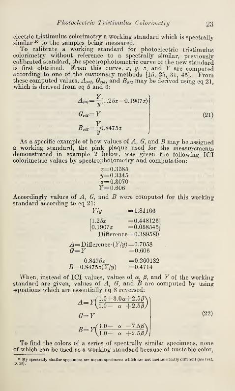
electric tristimulus colorimetry a working standard which is spectrallysimilar 20 to the samples being measured.To calibrate a working standard for photoelectric tristimulus
colorimetry without reference to a spectrally similar, previouslycalibrated standard, the spectrophotometric curve ol the new standardis first obtained. From this curve, x, y, z
,and F are computed
according to one of the customary methods [15, 25, 31, 45]. Fromthese computed values, Astd ,
Gstd ,and Bstd may be derived using eq 21,
which is derived from eq 5 and 6:
Astd='-(l.25x-0.1907z)y
o,u=r
Bsia=^0M75z
(21 )
As a specific example of how values of A, G, and B may be assigneda working standard, the pink plaque used for the measurementsdemonstrated in example 2 below, was given the following ICIcolorimetric values by spectrophotometry and computation:
2=0.3585
y= 0.33452=0.3070F=0.606
Accordingly values of A, G, and B were computed for this workingstandard according to eq 21:
Y/y =1.81166
[1.25a; =0.44812510.19072 = 0.058545
[
Difference= 0.389580
A= Difference- (F/y)= 0.7058
G=Y =0.606
0.84752 =0.260182B=0M75z(Y/y) =0.4714
When, instead of ICI values, values of a, jS, and F of the workingstandard are given, values of A, G, and B are computed by usingequations which are essentially eq 8 reversed:
A= 1.0+3.0a+2.5/3\1.0- a +2.50/
G=Y1 .0-1 .0-
a -7.5Aa +2.50/
(22)
To find the colors of a series of spectrally similar specimens, noneof which can be used as a working standard because of unstable color,
30 By spectrally similar specimens are meant specimens which are not metamerically different (see text,
p. 25).

24 Circulars of the National Bureau of Standards
a stable plaque is assigned values of A, G, and B which relate to theimpermanent specimens rather than to its own color. To calibratesuch a working standard, one of the unstable specimens must bemeasured on a spectrophotometer and then compared immediatelywith the stable plaque on the tristimulus instrument.
VI. ERRORS IN PHOTOELECTRIC TRISTIMULUSMEASUREMENTS
In the paper describing the multipurpose reflectometer [18J, 18potential sources of instrument error are listed. These 18 sourcesinclude most of those which will be found in photoelectric tristimulusinstruments, and it is believed, therefore, that no further study of theerrors of instruments is needed here. With special reference to theerrors of photoelectric tristimulus colorimetry, however, there areseveral matters which merit attention. These matters are consideredherein with particular reference to measurements with the author’sthree-filter multipurpose reflectometer.
It should be pointed out first that high precision is needed for useful
photoelectric tristimulus measurements. In order to identify by aninstrument, chromaticity differences as small as can be distinguishedby an experienced observer, relative values of A, G, and B must behighly precise. To show what this precision must be, changes of 0.001
in the instrument settings on a hypothetical white surface and on ahypothetical yellow surface have been converted to correspondingchanges in x, y )
a,
/S, AE, and W by using the relations above. Theseare shown in table 6.
Table 6.— Amounts of change in chromaticity and color difference introduced bychanges in instrument settings of 0.001
J
For a white1 surface re-
1
fleeting 80percent
For a yellowsurface re-
flecting 35percent
\A 0.800 0.500.800 .350
Ib_ - .800 .050
\A .801 .501.799 .349
1B .801 .051
/in x... +. 00024 +.00049in y -.00054 -.00182in a. _ ... +. 00062 +. 00160in e -.00025 -.00064
in V« 2+0 2 .00067 .00172in AE (maximum,NBS units).- ±.45 ±.94
.in W -.0025
If settings of the instrument should be_
Changes of the following magnitudes will result-
Under favorable observing conditions, a trained inspector can usu-ally distinguish as different the colors of two light-colored surfaces if
A£’=0.3,
or if V^?+^2=0.0005.
In general, it can therefore be said that a tristimulus colorimetergiving apparent reflectances imprecise by 0.001 will not serve to iden-

Photoelectric Tristimulus Colorimetry 25
tify color differences as small as those which the trained color inspectorcan distinguish.
Although the individual settings of a multipurpose reflectometerare usually uncertain by more than 0.001, a technique is used to obtainsettings with this instrument which ordinarily reduces the errors ofthe resulting values of x, y, a, (3, AE, and W to considerably less thanthose given in table 6. With this instrument the settings on eachspecimen with the three filters are made consecutively. By thustaking settings with the three filters almost simultaneously and withoutmoving the specimen, the errors ordinarily introduced by temperaturedrift and by change of the position of the specimen between exposuresare minimized in the computed differences between the settings.
It may be seen from eq 8 above that the chromaticity measurementof a sample depends chiefly upon these differences between settings.
These differences must be uncertain by less than 0.001 for precise
photoelectric colorimetry, since changes in the differences betweenA, G, and B are relatively more important in determining chromaticitythan changes in their magnitudes. The three readings of a samplewould have to be simultaneously high, or simultaneously low by fourtimes 0.001 (for a near-white sample) to cause a lightness-componenterror in AE as large as the chromaticity-component error caused byan inaccuracy in A-G of 0.001. Resort to eq 13 above will verify
this conclusion.
1. ERRORS IN TRISTIMULUS MEASUREMENTS OF CHROMATICITYDIFFERENCE DUE TO SPECTRAL INACCURACY OF THE SOURCE-FILTER-PHOTOCELL COMBINATIONS
The spectral inaccuracy of the source-filter-photocell representationof the ICI standard observer has been demonstrated above. Althoughthe errors from this source were shown [18] to be not serious in measure-ments of luminous apparent reflectance, the errors from the samesource are serious in measurements of chromaticity.
It was pointed out by Perry [40] that these chromaticity errors are
small and can usually be tolerated when the photoelectric tristimulus
method is used to measure differences in chromaticity between spec-
trally similar, or as he said, “spectrophotometrically similar” specimens.Under other circumstances, however, the chromaticity errors
are frequently larger than can be tolerated. It can only be recom-mended, therefore, that the present method be used to measure color
differences between spectrally similar specimens.Before undertaking quantitative evaluations of chromaticity errors,
it seems desirable to explain in some detail what Perry meant when hespoke of “spectrophotometrically similar” specimens. Actually a
word suggested by Ostwald [39], “nonmetameric”, seems to applymore specifically than either spectrally similar or spectrophoto-
metrically similar to the property of the differences which is important.
The stimuli produced by two illuminated specimens are metamerswhen there is a spectral difference between them which is of such a
nature that they nevertheless have the same color. As an example,
there is the frequently cited case of two specimens which have the samecolor under one illumination, but different colors under a second illu-
mination. Under the first illumination, the two stimuli are metamers

26 Circulars of the National Bureau of Standards
for the specimens have to be spectrally different to appear different
in color under the second illumination.
In the present discussion, reference is made to “degree of meta-
merism.” It is supposed that the spectral difference for two speci-
Figuhe 6.—Spectral curves of four pairs of specimens used for the study of amounts
of error resulting from failure of the source-filter-photocell combinations to be
spectrally equivalent to the ICl standard observer.
Upper two pairs—curves representing essentially nonmetameric differences; lower two pairs—curves
representing differences in which there is appreciable metamerism.
mens under a given illumination can be separated into three compo-
nents: (1) a factor of constant proportionality throughout the spec-
trum corresponding to the lightness difference, (2) a component which
is responsible for the chromaticity difference, and (3) a metameric
component yielding no color difference.

Photoelectric Tristimulus Colorimetry 27
In general, the chromaticity error in photoelectric tristimulus mea-surement increases with the size of the latter two components. Forpairs yielding no appreciable metameric component, therefore, thesize of the chromaticity error is roughly proportional to the size ofthe chromaticity difference.
In order to find the approximate factor relating chromaticity errorto size of nonmetameric chromaticity difference, and to show also thatthis factor fails to evaluate the amount of error when there is appre-ciable metamerism, four chromaticity differences were carefullystudied. The errors of these four differences were computed from thespectral curves of the eight specimens involved. With each of the fourpairs, one specimen was assumed to represent a standard and the otheran unknown sample. True (a, 0) and approximate (photo-electric) values of chromaticity were computed, using the spectralspecifications of the ICI observer and the source-filter-photocell com-binations, respectively. True chromaticity differences were thencompared with the corresponding photoelectric-tristimulus chroma-ticity differences to obtain the errors of the latter values.
The spectral curves of the four pairs of specimens are shown in
figure 6. With the top two pairs there is relatively little metamerism;with the bottom two there is significant metamerism. For the first
pair, MgO and Munsell paper BPB 8/2 were chosen. The Munsellpaper was chosen to represent a specimen which differed in chroma-ticity from MgO by about as much as any specimen which would becalled “near white.” Perry pointed out that because white and near-
white specimens were relatively nonselective, significantly metamericdifferences between them were rare. Realizing that a photoelectric
tristimulus colorimeter thus possessed special advantages for use onwhite materials, Perry named the device which he designed theBlancometer [40].
The two yellow papers, Y1 and Y2, are very nearly alike in color;
in fact the perceived color difference between them will change in
character with change from daylight to incandescent illuminant.
Thus they represent a case in which the spectral difference is chiefly ametameric difference. The degree of metamerism is even greater for
the difference between the two gray samples, Gl and G2.
The true chromaticity differences and the computed errors of the
photoelectric tristimulus method are given for the four pairs of speci-
mens in table 7. Since these data are computed from the spectral
curves of the specimens, the errors shown are those due solely to the
spectral inaccuracy of the source-filter-photocell combinations.
From table 7 it can be seen that if sample and standard are not meta-merically different, photoelectric tristimulus measurements of chro-
maticity difference may be in error by roughly 10 percent of the dif-
ference measured. If there is appreciable metamerism, however, the
error is not related to the size of the chromaticity difference. Forthis reason parentheses have been placed about thv latter two “per-
cent errors” in table 7.

28 Circulars of the National Bureau of Standards
Table 7.—Errors in measured chromaticity differences which resultfrom substitution
of 'photoelectric tristimulus combinations for the ICl standard observer
Specimens compared
Size of thechromaticitydifference
Aa^-^AfJ2
Error in the photoelectricallymeasured chromaticity dif-
ference
ActualRelative to
size of differ-
ence
Munsell BPB 8/2 and MgO. 0.0229 0. 0013%
6
BG 6/4 and BG 7/4 .0150 .0018 12
Yellow Y1 and vellow Y2 . 00187 .00043 (23)
(38)Gray 01 and gray 02 .0160 .0061
In figure 7 there is experimental confirmation of the conclusion that
errors are small in the measurement of the chromaticities of whitesamples. Points representing twelve white porcelain-enameledplaques which were measured with both the multipurpose photoelec-
tric reflectometer and the visual, subtractive colorimeter [29] are
plotted in this figure. The plaques were compared in both instru-
ments with a Yitrolite standard, for which the assigned chromaticityis shown. For none of the plaques is the disparity as great as 0.001 in
Vaz2+ Ay2
, even though it includes the errors of both instrumentsas well as the error due to spectral inaccuracy of the source-filter-
photocell combinations. To show how large a part of the total
(x,
y
)-diagram is covered by figure 7, its boundaries were plotted as asmall rectangle near the center of figure 2.
The errors represented in table 7 and figure 7 have involved onlysmall chromaticity differences. In figure 2, above, there is evidencewhich extends to large chromaticity differences the findings abouterrors given in table 7 for small differences. If distances betweenthe different pairs of points representing the same colors are measuredin figure 2, it will be found that they are, on the average, roughly one-tenth the respective distances from these points to the white pointcommon to both diagrams. Since magnesium oxide, representedby the white point, was the standard against which the several speci-
mens were measured, this average error of one-tenth the chromaticitydifference is in good agreement with the errors of roughly 10 percentindicated in table 7. Thus one may expect errors which will averageabout 10 percent of the measured chromaticity differences for large
as well as small nonmetameric differences.
2. CHANGES IN MEASURED CHROMATICITY RESULTING FROMCHANGE OF PHOTOCELL IN AN INSTRUMENT
Of the three components of each source-filter-photocell combina-tion, the photocell is in practice the most difficult to duplicate spec-trally. In the absence of an evaluation of errors possible from all thesecomponents, it may be instructive to evaluate the changes in measuredchromaticity which can result from change from one photocell in aninstrument to another of the same manufacture. Of the several GEcells for which data were available, the cell most different in spectralresponse from cell No. 55 was cell No. 2. The relative spectralresponses for these two cells are compared in figure 8.
The photoelectrically measured chromaticity difference for eachpair of samples identified in figure 6 would change with substitution of

Photoelectric Ti'istimuZus Colorimetry 29
cell No. 2 for cell No. 55. The amounts of these changes were com-puted in the same way as the errors reported in table 7, and are givenin table 8. It will be noted that the changes in computed chroma-ticity difference are somewhat smaller than the errors for the corre-
sponding pairs reported in table 7, but the changes are neverthelesslarge enough to be important.
.320
.315
y
.310
.305
.300 .305 .310 .315
XFigure 7.—Part of (x,y) -diagram (outlined by rectangle in fig. 2
,above) showing
x and y of a number of white porcelain-enameled plaques measured both with the
visual subtractive colorimeter [29] and with the multipurpose reflectometer [18].
Table 8.—Changes in measured chromaticity difference which would result from the
substitution of one photocell for another of the same type, but of different spectral
response
Specimens compared
Measured size
of the chroma-ticity difference
Change in the measured chro-maticity difference with sub-stitution of cell
(with cell 55)
y/^+Ap ActualRelative to size
of difference
Munsell BPB 8/2 and MgO 0. 0261 0. 0016%
6BO 6/4 and BO 7/4 .0136 .0004 3Yellow Yl and yellow YU.. .00224 .00035 (16)
(13)Gray 01 and Gray Gi .0184 .0024
O FROM SUBTRACTIVE COLOR-IMETER
024ss2a
O FROM MULTIPURPOSEREFLECTOMETER
10’
9°0
f/JTROLlTE
29
€>Z\
M 90; q2Z & o'*oO ©23
&0On
30 Circulars of the National Bureau of Standards
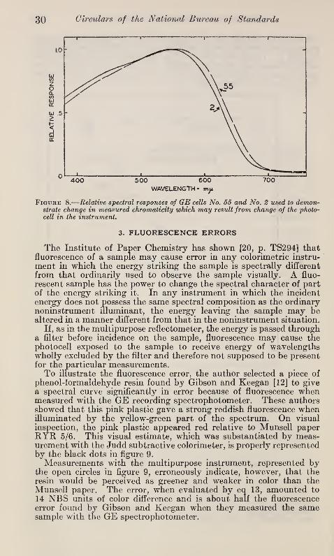
Figure 8.—Relative spectral responses of GE cells No. 55 and No. 2 used to demon-strate change in measured chromaticity which may result from change of the photo-cell in the instrument.
3. FLUORESCENCE ERRORS
The Institute of Paper Chemistry has shown [20, p. TS294] thatfluorescence of a sample may cause error in any colorimetric instru-
ment in which the energy striking the sample is spectrally different
from that ordinarily used to observe the sample visually. A fluo-
rescent sample has the power to change the spectral character of partof the energy striking it. In any instrument in which the incidentenergy does not possess the same spectral composition as the ordinarynoninstrument illuminant, the energy leaving the sample may bealtered in a manner different from that in the noninstrument situation.
If, as in the multipurpose reflectometer, the energy is passed througha filter before incidence on the sample, fluorescence may cause thephotocell exposed to the sample to receive energy of wavelengthswholly excluded by the filter and therefore not supposed to be presentfor the particular measurements.To illustrate the fluorescence error, the author selected a piece of
phenol-formaldehyde resin found by Gibson and Keegan [12] to givea spectral curve significantly in error because of fluorescence whenmeasured with the GE recording spectrophotometer. These authorsshowed that this pink plastic gave a strong reddish fluorescence whenilluminated by the yellow-green part of the spectrum. On visual
inspection, the pink plastic appeared red relative to Munsell paperRYR 5/6. This visual estimate, which was substantiated by meas-urement with the Judd subtractive colorimeter, is properly representedby the black dots in figure 9.
Measurements with the multipurpose instrument, represented bythe open circles in figure 9, erroneously indicate, however, that the
resin would be perceived as greener and weaker in color than theMunsell paper. The error, when evaluated by eq 13, amounted to
14 NBS units of color difference and is about half the fluorescence
error found by Gibson and Keegan when they measured the samesample wdth the GE spectrophotometer.

Photoelectric Tristimulus Colorimetry 31
Figure 9.—Error in photoelectrically measured chromaticity due to fluorescence ofthe resin specimen
,R.
When compared in the subtractive colorimeter [29] with Munsell paper RYE 5/6, the resin is properlyassigned the chromaticity represented by the black dot, rather than the erroneous chromaticity assignedby the multipurpose reflectometer [18J and represented by the [open circle.
4. SHORT CUTS IN COMPUTATION WHICH PRODUCEONLY SMALL ERRORS
There are several short cuts which at times may be used to reducethe labor of computing tristimulus quantities from settings with themultipurpose reflectometer. The shortened procedures result in
errors which diminish with the computed color difference between thespecimens compared. With many small color differences, therefore,
the short-cut computational errors are smaller than the errors intro-
duced by lack of precision and are therefore unimportant. Evenlarger errors from this cause are unimportant if they are appreciablyless than the maximum error permitted for a successful solution of
the problem.As an example, short-cut errors are seldom serious when one is
following the day-to-day change of the color of a paint or textile
material due to fading or other cause. The highest accuracy is notnecessary for such measurements so long as the day-to-day repro-
ducibility is fairly good. The short-cut computational .errors havenegligible effect on this reproducibility.
(a) OMITTING SCALE CORRECTIONS
In practice, the apparent-reflectance scale supplied with a multi-
purpose reflectometer is not exact. Correction curves, which are
found by calibration after the instrument is completed, are necessaryto obtain accurate values with the device [18, p. 601; 18a, p. 548].
The corrections do not change value rapidly with the scale readingfor most parts of the scales employed. Therefore the omission of
scale corrections usually produces only small changes in the computedcolor differences between samples of similar color. In all but oneof the examples of tristimulus color measurement reproduced below,
in section VIII, the scale corrections were omitted.
(b) NEGLECT OF THE DIFFERENCE BETWEEN THE KNOWN A, G, AND B VALUESFOR THE STANDARD AND THE APPROXIMATE VALUES READ DIRECTLY FROMTHE INSTRUMENT
Because of the usual drift of instrument readings with time, the
difficulty of making minute adjustments of photometric balance, and

32 Circulars of the National Bureau of Standards
the frequent necessity of correcting readings for scale errors, the read-ings of a photoelectric tristimulus instrument seldom give accuratevalues of A, G
,and B directly. Instead, values of A, values of G,
and values of B each relative to those of the standard are obtainedfrom instrument settings, after the effect of drift is balanced out in
the manner illustrated in examples 1, 3, 5, and 6, below. Thus if
one exposes a standard and two samples for which the accuratetristimulus values are
Aam, Gstd)
Gi, B l
A2 ,g2 ,
B2 ,
he actually obtains from the corrected settings
haAsx&i kgGat&, h}yBSXA.
haA\, kgG\, kbBi
kaA2 ,kgG2 ,
k^B2 -
For many cases in which the highest accuracy is not required, it
is not worthwhile to evaluate ka ,kg ,
and & 6 ;their departures from unity
are found to be negligible. In examples 3 and 4, section VIII, usewas made of this short-cut B.One might suppose that a simple additive method could be used
to compute accurate tristimulus values from instrument readings. If
such a procedure were possible, one could take settings on a standardand sample, and from these settings compute values of x and y. Fromthe computed and known values of x and y for the standard, the sup-posed additive corrections, Ax and Ay, would be found. That suchcorrections applied additively are inexact, however, may easily beshown. An “uncorrected” value of x for the standard would becomputed from the readings on it by:
, n__ 0 .80&gA8td-}- 0 . 1 8k^Bstd
8td u0.80&aAst(iA^g^stdH- 1 *36&j,i58 t(i
whereas the true value of x would be
0.80A8td+ 0 . 1 8l?8tdBtd 0.80Aatd+£8td+1.365st(i
*
It will be seen that there is no simple function of ;rBtd(M) and z8td bywhich the factors ka ,
kg ,and k b can be eliminated.
(c) USING 0.5 AND 0.1 INSTEAD OF THE ACCURATE VALUES FOR THE NEUTRAL-FILTER TRANSMISSION FACTORS
To extend its photometric range, the multipurpose reflectometer
makes use of two neutral filters transmitting approximately 0.5 and0.1, respectively, of the normally incident energy. Actually the
transmissions of the two filters used in the author’s instrument are

Photoelectric Tristimulus Colorimetry 33
not 0.5 and 0.1, nor are the filters ideally neutral. Instead the trans-missions are as follows:
Nominal trans-missions of“neutral”filters
Exact transmissions of “neutral” filters
For amber tri-
stimulus filter
For green tri-
stimulus filter
(giving lumi-nosity func-
tion)
For blue tri-
stimulus filter
0. 5. 1
0. 480. 088
0. 479. 086
0. 427. 065
When the color differences between the specimens being comparedare very small, or when accuracy is not needed, use of 0.5 and 0.1
instead of the proper filter factors is frequently permissible. It shouldbe obvious, however, that these approximate factors should not beused for the computations if the neutral filter employed in conjunctionwith any one of the tristimulus filters was changed during the settings
on the group of specimens. Example 4, section VIII, illustrates this
third short cut.
(d) AMOUNTS OF ERROR FROM USING SHORT-CUT METHODS
To give an idea of the sizes of the errors which would be found in
actual practice, instrument settings for six typical color differences
were converted to amounts of color difference, first by the accuratecomputational procedure and then by using the short cuts. Twowhite, two delphinium-blue, and two international-orange pairs of
samples were chosen, so that for each color there was one difference
of about 1.5 NBS units and one of about 7 units. For each color, pairs
of samples were sought which seemed likely to give the most serious
errors from the use of the short-cut methods. For these pairs,
amounts of color difference were computed five times; first they werecomputed accurately, then each of the three short cuts was usedseparately, and finally they were used together.
Table 9.—Percentage errors in computed values of color difference from using the
suggested short cuts
Errors in percentage of total difference
—
Short cutFor two pairs ofwhite samples
For two pairs of
blue samplesFor two pairs of
orange samples
AU=1.8 AE=6.6 > ii o AjE=7.6 AE=1A AE=6.0
Scale corrections omitted _ _ 0.6 1.
1
0 4.1 4.2 4.8
Use of instrument values of A, G, and B,having only relatively correct magni-tudes _ ... ... _ _ ... 0 0 1.0 2.9 26.6 6.3
Use of 0.5 and 0.1 instead of true neutral-filter factors.. 3.9 3.6 7.7 1.0
Combination of above three short cuts 0.6 0.3 0 8.7 27.3 4.8
The errors are given in table 9 as percentages of the accurately
computed differences. The size of each error depends upon the nature
of the color difference involved as well as upon the spectral selectivity

34 Circulars of the National Bureau of Standards
of the samples, and hence some of the differences are surprisingly
small. In general, it will be seen that the errors become larger as thesamples become more strongly colored. It will also be seen that theerrors from the use of more than one short cut are not always additive.
By comparison of the percentage errors in table 9 with those in table 7,
it will be seen that most of these short-cut errors are smaller than theerrors from spectral inaccuracy of the source-filter-photocell com-binations. For this reason the short cuts can be recommended for usein many photoelectric tristimulus comparisons of color in which thehighest accuracy possible is not needed.
VII. THE RELATION OF PERCEPTUAL IMPRESSIONS ANDMEASURED VALUES OF COLOR
Because the ICI standard observer was created from the color
matches made by a number of normal observers [13, 51], the numericaldescription of a color difference in the ICI or a related color systemwill, if possible interfering circumstances are eliminated, indicate thecharacter of the color difference perceived and described by the normalobserver. With some of the methods of measuring color suggestedin the present paper, however, numbers are given which, in addition
to indicating the character of the difference, are intended to designatequantitatively the perceptual impression of the difference. Un-fortunately there is at present little information on the success withwhich quantitative perceptual impressions are duplicated by thesephotoelectric tristimulus measurements. One bit of information maybe noted. In a study of several methods for measuring color dif-
ference, Balinkin [1] compared the photoelectrically measured valuesof AE for 10 pairs of green porcelain tiles with the averages of thevisual estimates of the same differences by 60 observers. He foundfairly good agreement between measured and estimated values, witha correlation according to ranks of 0.86.
A number of the circumstances which may disturb the correspond-ence between visual estimates and photoelectric determinations of
color and color difference are well known. Some of these circum-stances relate to imperfections in the measuring method, others to
imperfections in the observing situation. There follows a two-partlist in which a number of the circumstances are given. It will beseen that each of those listed under “imperfections in the measuringmethod” was discussed above.

Photoelectric Tristimulus Colorimetry 35
CIRCUMSTANCES WHICH MAY INTERFERE WITH CORRELATIONBETWEEN VISUALLY ESTIMATED AND PHOTOELECTRICALLYMEASURED VALUES OF COLOR AND COLOR DIFFERENCE
Imperfections in the Measuring Method:
Error from spectral inaccuracy of source-filter-photocell com-binations.
Error from fluorescence of sample.Error from photometric inaccuracy of measuring instrument.Failure of the empirically chosen scales for chromaticity, surface-
color difference, and lightness to represent appropriate scales
for these quantities.
Imperfections in the Observing Situation:
Spectral difference between illuminant used for observations andICI illuminant C.
Angular difference between directions of illuminating and viewingused for the visual observations and those used for the meas-urements. (This factor frequently affects the correlation if
appreciable specularly reflected light is present in one case,
but is eliminated in the other.)
Differences in texture and shape of the specimens being com-pared.
Nonuniformity of color from point to point on some of the speci-
mens. (For instrument measurements of pairs of specimens,central areas are usually used; for visual comparisons, thecolors of the immediately adjacent areas of the specimenshave the greatest influence on estimated color difference.)
Failure to take proper account in the measured values of thecharacter of the dividing line, separating pattern, or back-ground used during visual observation.
Abnormality of the observer, either temporary as from fatigue,
or permanent as with an observer having abnormal color
vision.
VIII. EXAMPLES
To demonstrate uses of the photoelectric tristimulus method, andto illustrate forms for recording the corresponding data, six exampleshave been prepared. These examples represent multipurpose reflec-
tometer measurements made at the National Bureau of Standards for
purposes which have been identified on each of the forms which is
shown. All of the steps leading from the initially recorded settings
to the desired values for color have been duplicated. The numberof settings taken on each sample and the short cuts permitted in thereduction of the data were decided in each case by a consideration of
the needs for precision and accuracy of the problem at hand. When-ever two readings were made with each filter for every specimen, theorder of readings was: Standard, No. 1, No. 2, No. 3,
* * * No.3, No. 2, No. 1, Standard. This symmetrical order, which was usedto eliminate some of the error of drift, was mentioned above. Theequations used in the following examples are given in table 3 and in
the text above.

36 Circulars of the National Bureau of Standards
Example 1.—Measurement of the ICl values, x, y ,
z, and Y of four white paintedplaques (see eq 5 and 6
,and fig. 10.)
Purpose—To test samples for compliance with color requirements given inFederal Specification TT-P-23a [8], namely,
x y z YMinimum 0. 355 0. 85Maximum 0. 324 0. 331
Computational short cut—Scale corrections omitted.Working standard—vitrolite No. 1 (A= 0. 906, G=0. 909, 73=0. 890).
Specimen Standard No. 1 No. 2 No. 3 No. 4
Blue settings JO. 89851 . 8955
. 8970
0. 8480. 8450. 8465
0. 7900. 7880. 7890
0. 7810. 7790. 7800
0. 7080. 7070. 7075Mean.. _
0. 890. 8398 . 7828 . 7739 . 7020^ 0. 8970
"
Amber settings _ _ __ JO. 9055
t . 9030. 9042
0. 8785. 8770. 8778
0. 8720. 8680. 8700
0. 8420. 8400. 8410
0. 8530. 8520. 8525Mean_
. 0.906A—mean _ . 8795 . 8717 . 8427 . 8542x 0.9042
Green settings _ __JO. 91001 . 9070
. 9085
0. 8770. 8740. 8755
0. 8620. 8585. 8602
0. 8340. 8320. 8330
0. 8320. 8310. 8315Mean _ _ _ _ __
Tr . „ 0.909i == (j— mean X a aao r . . 8760 . 8607 . 8335 . 8320
0.9085
0.18 B 0. 1512 0. 1409 0. 1393 0. 12641.18 B . 9910 . 9237 . 9132 . 82840.80 A+ 0.18 B . 8548 . 8383 . 8135 . 8098Denominator ((7+0.80 + +1.36 B) 2. 7218 2. 6227 2. 5602 2. 4702
0.80 A 4-0.18 BX =—3 : 7 _ 0. 3141 0. 3196 0. 3177 0. 3278denominator
y ^^/denominator . 3218 . 3282 . 3256 . 3368
z = 1 . 1 8i3/denominator . 3641 . 3522 . 3567 . 3354
Result of test Pass Fail Fail Fail
(*) (Y) (all)

Photoelectric Tristimulus Colorimetry 37
XFigure 10.—Part of the (x,y)-diagram showing chromaticities acceptable and
chromaticities not acceptable according to Federal Specification TT-P-23a for
white casein paints.
The plotted points show values obtained with actual samples.

38 Circulars of the National Bureau of Standards
Example 2.—Measurement of the change of a and /3 of three painted plaques withexposure (see eq 8 and fig. 11)
Purpose—To follow the chromaticity changes of panels of the same paint exposedout of doors and in two machines which accelerate the changes pro-duced by weathering.
Note—Only one of the many sets of computations used to obtain values of a and/3 is reproduced below.
Computational short cut—Scale corrections omitted.Working standard—pink plaque (A= 0.7058, G= 0.606, 15=0.4714).
Specimen Standard Roof(4 days)
Machine 1
(43 hours)Machine 2
(41 hours)
Blue settings / 0. 4995 0. 300 0. 685 0. 597l . 501
Mean . 5002_ ... 0.4714-D— SettingX n -nno . 2827 . 6453 . 5626& 0.o002
Amber settings / . 704 . 510 . 7075 . 675
{ . 704Mean . 704
, ... 0.7058A.= settingX n ’-rn a . 5113 . 7093 . 6767
Green settings / . 620 . 424 . 708 . 656{ . 619
Mean . 6195„ ... 0.606
(JC settingX ^ n 1 r . 4148 . 6926 . 64170.6195
A—G ___ + • 0965 +. 0167 + . 0350G-B + • 1321 +. 0473 +. 07910.4 (G—B) . __ +. 0528 +. 0189 +. 0316B+A+2G= denominator _ 1. 6236 2. 7398
j
2. 5227
a — (A— (?) /denominator. + 0. 0594 + 0. 0061 + 0. 0139£=0.4((?— B)/denominator +. 0325 +. 0069 +. 0125

Photoelectric Tristimulus Colorimetry 39
One fact is worthy of comment in connection with the changes of
chromaticity accompanying fading of the paint illustrated in figure 11.
At the start of exposure, a change in the paint from moderate pink to
weak orange took place. This pronounced hue change is unusual in
Figure 11 .—Part of the (<x,0) -diagram used to show the changes of chromaticity ofa pink-colored paint with exposure outdoors and in two machines designed to
accelerate the changes produced in weathering.
fading; paints, textile, and other materials are usually perceived to
become merely weaker in color as the result of exposure to light, heat,
and humidity. The usual curve of chromaticity change with time of
exposure is therefore merely a curve directed toward the origin of the
(a,/3)-diagram, similar to the curves of figure 11 beyond the points
showing the initial hue change.

40 Circulars of the National Bureau of Standards
Example 3.—Measurement of the amount of color difference, AE, between a standardand each of four similarly colored brown automobile pile fabrics (see eq 18).
Purpose—To find which fabrics comply with the requirement that they differ
from the standard by no more than one NBS unit of color difference.
Computational short cut—No calibrated standard used.
fci= 100, /„=1.00.
Fabric Standard No. 1 No. 2 No. 3 No. 4
Blue settings (with 0.427 filter) __
Mean (M)
/ 0. 1700
l . 1688. 1694
0. 1744. 1738. 1741
0. 1620. 1618. 1619
0. 1690. 1686. 1688
0. 2024. 2018. 2021
Scale correction — . 0139 — . 0138 —. 0138 0136 —
. 0121Corrected M . 1555 . 1603 . 1481 . 1552 . 1900
J3= Above times .427 . 0664 . 0684 . 0632 . 0663 . 0811
Amber settings (with 0.480filter)
_
/ . 20981 . 2082
. 2144
. 2142. 2022. 2018
. 2042
. 2036. 2524. 2520
Mean (M) . 2090 . 2143 . 2020 . 2039 . 2522Scale correctionCorrected M_
0120. 1970
0120. 2023
0120. 1900
-. 0120. 1919
-. 0113. 2409
A= above times .480 . 0946 . 0971 . 0912 . 0921 . 1156
Green settings (with 0.479 fil-
ter) _ _
/ . 1916l . 1900
. 1946
. 1944. 1848. 1844
. 1882
. 1876. 2300. 2302
Mean (M) . 1908 . 1945 . 1846 . 1879 . 2301Scale correction -. 0127 —
. 0126 —. 0130 —
. 0129 —. 0122
Corrected M . 1781 . 1819 . 1716 . 1750 . 2179Y— G= Above times .479 .0853 . 0871 . 0822 . 0838 . 1044
A-G +. 0093 +. 0100 +. 0090 + . 0083+ . 0175
+ . 0112G-B +. 0189 +. 0187 +. 0190 +. 0233
+. 0093. 4055
0.4 (G-B) + . 0076 +. 0075 +. 0076 +. 0070Denominator=B+A+ 2G . 3316 . 3397 . 3188 . 3260
a= (A— G)/denominator _ 4-. 0280+. 0229
+. 0294 +. 0282+. 0238
-f . 0255+. 0215
+. 0276/3 = 0A(G—B)/denominator +. 0221 +. 0229
Aol— ol— astd _ + . 0014 + . 0002 -. 0025 0004A/3=/3— /3std — —
. 0008 +. 0009
. 09
—. 0014 . 0000
Va^+ A^-IOs _ . 16 . 29 . 04
yi/2. 292 . 295 . 287 . 289 . 323
7(F74)* 3. 78 3. 98
AC= 7(y1/4)VAa2+ A/32 - 102
. 60 . 34 1. 10 0. 16
AY1/2
_ +. 003 — . 005 -0. 003 +. 031AL=k 1 (AYV2
) . 3 . 5 . 3 3. 1
> -s II< $ .67 . 60 1. 14 3. 11
AE|
0. 7 0. 6 1 . 1 3. 1
1
•Compute 7(yV4) for standard and for any samples for which the value of Ydiffers from that ofthe standard
by more than 10 percent. For the latter samples, use the mean of the two values of 7(F1/4); for others,
use the value for the standard.
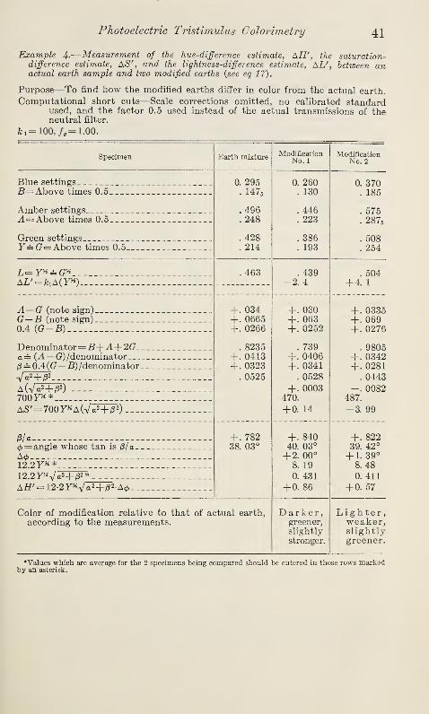
Photoelectric Tristimulus Colorimetry 41
Example —Measurement of the hue-difference estimate,AH', the saturation-
difference estimate, AS', and the lightness-difference estimate, AL', between anactual earth sample and two modified earths (see eq 17).
Purpose—To find how the modified earths differ in color from the actual earth.
Computational short cuts—Scale corrections omitted, no calibrated standardused, and the factor 0.5 used instead of the actual transmissions of theneutral filter.
ki= 100,/o =1.00.
!
Specimen Earth mixture ModificationNo. 1
ModificationNo. 2
Blue settings 0. 295. 1476
. 496
. 248
. 428
. 214
0. 260. 130
. 446
. 223
. 386
. 193
0. 370. 185
. 575
. 2876
. 508
. 254
B= Above times 0.5
Amber settings.
A= Above times 0.5
Green settings
Y—G= Above times 0.5
. 463 . 439-2. 4
. 504+ 4. 1
__ _ _
AL'= fciA(Y*) __
A— G (note sign) _ _ +. 034+. 0665+. 0266
. 8235+. 0413+ . 0323
. 0525
+. 030+. 063+. 0252
. 739+. 0406+. 0341
. 0528
+• 0003470.
+ 0. 14
+. 0335+. 069+. 0278
. 9805+ . 0342+. 0281
. 0443
0082487.
-3. 99
G—B (note sign)
0.4 (G—B) _
Denominator
=
B+A+2Ga = (A—G) /denominator/3 = 0.4 ((?— B) /denominator
Va2+ j82
A (V
a
2+ /S2) _ __
700YH *
A£'= 700y*A(Va2+ |52)_._
/3/ a + . 78238. 03°
+. 84040. 03°
+ 2. 00°
8. 19
0. 431
+0. 86
+. 82239. 42°
+ 1. 39°
8. 480. 411
+0. 57
0= angle whose tan is /3/a
A <j>
12.2F**12.2y*Va2+ /3
2 *
AH'— 12-2YkVa 2+ /32 -A</>
Color of modification relative to that of actual earth,according to the measurements.
Darker,greener,slightly
stronger.
Lighter,weaker,slightlygreener.
Values which are average for the 2 specimens being compared should be entered in those rows markedby an asterisk.
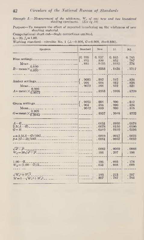
42 Circulars of the National Bureau of Standards
Example 5.—Measurement of the whiteness,W, of one new and two laundered
sheeting specimens. (See eq 19)
Purpose—To measure the effect of repeated laundering on the whiteness of newsheeting material.
Computational short cut—Scale corrections omitted.
Jfci= 20, /o=1.00.
Working standard—vitrolite No. 1 (.4=0.906, (?=0.909, £=0.890).
Specimen Standard New 1L 20L
Blue settings JO. 898
\ . 892. 895
0. 837. 850. 8435
. 8388
0. 845. 852. 8485
. 8438
0. 765. 787. 776
. 7717
MeanD 0.890B—meanX a~oTTk -- _ _^ 0.895
Amber settings / . 9085
t . 906. 9072
. 892
. 904
. 898
. 8968
. 912
. 912
. 912
. 9108
. 826
. 836
. 831
. 8299
Mean4 v °-906A= meanX q qq
i
j2 -
Green settings _ _ / . 90551 . 903
. 9042
. 884
. 894
. 889
. 8937
. 900
. 900
. 900
. 9048
. 812
. 824
. 818
. 8223
Mean„ v 0.909(j^meanXn aau.x 0.9042
A-G . 0031. 0078. 0549
. 0009
. 0061
. 0060
. 0150
. 0610
. 0017
. 0067
. 0076
. 0190
. 0506
. 0023
. 0062
2.5(4L-(7)__G—B. __
a — 2.5(A— G)/lOG/?= (G—B)fl0G
V«2+ /32_ _ _ _ __ __ . 0062. 186
. 0069
. 207. 0066
. 198Wc= 30Va2+ /32 - - - -
1.00— G _ _ . 106. 053
. 095
. 048. 178. 089Wl =(1.00— G)/2
JWc2+Wl
2. 193. 807
. 213
. 787. 217. 783w— 1—VWc2+ WL
2

Photoelectric Tristimulus Colorimetry 43
Example 6.—Measurement of the yellowness of four near-white porcelain-enameledspecimens (eg 20).
Purpose—To find which of several enamel specimens are yellowish (+ values)and which are bluish (— values).
Computational short cut—scale corrections omitted.Working standard—vitrolite No. 1 (A= 0.906, G= 0.909, -6=0.890).
Plaque No. Standard 1 10 22 24
Blue settings/0. 89551 . 8920
. 8938
0. 7540. 7490. 7515
. 7483
0. 7760. 7716. 7738
. 7705
0. 8238. 8222. 8230
. 8195
0. 7804. 7780. 7792
. 7759
MeanD . . 0.890B—meanX ^
0.8938
Amber settings / . 8945l . 8936
. 8940
. 7276
. 7222
. 7249
. 7346
. 7236
. 7176
. 7206
. 7303
. 7990
. 7962
. 7976
. 8083
. 7980
. 7962
. 7971
. 8078
Mean_ 0.906
A meanX 08940
Green settings
Mean„ 0.909
/ . 9037l . 9030
. 9034
. 7370
. 7316
. 7343
. 7389
. 7364
. 7324
. 7344
. 7390
. 8094
. 8074
. 8084
. 8134
. 8046
. 8030
. 8038
. 8088er mean Xq 9Q34
A— BYellowness= (A— B)/G (eq 20)
-. 0137-. 0185
-. 0402-. 0544
-. 0112-. 0138
+. 0319+ . 0394
IX. SUMMARYPhotoelectric tristimulus measurements are well suited for com-
parisons of the colors of spectrally similar specimens. In commercethere seem to be many situations in which such measurements mayprove to be useful: (1) in the day-to-day control of the colors of
materials in production, (2) in obtaining compliance of materials withcolor-tolerance requirements, (3) in making modifications of color to
produce matches, and (4) in the measurements of color changesaccompanying fading. For problems of this general character, it is
believed that photoelectric tristimulus measurements will prove to beuseful.
The advantages and disadvantages of photoelectric tristimulus
colorimetry have been summarized as follows:
ADVANTAGES
Small number of settings required for each sample.Small number of computational steps required to obtain x, y ,
and Y, or a, (3, and Y.Simplicity and inexpensiveness of apparatus.Opportunity to convert settings rapidly to numbers giving size
and character of color difference perceived between samples.
Correspondence between values of a, (3, and Y, and positions of
points representing colors in the uniformly spaced surface-
color solid.

44 Circulars of the National Bureau of Standards
DISADVANTAGES
Errors resulting from the inaccurate spectral response of thesource-filter-photocell combinations used.
The necessity for working standards which are spectrally similarto the samples measured.
The necessity for special precautions to attain the high precisionrequired if the tristimulus method is to equal the eye in powerto discriminate colors.
Failure of tristimulus measurements to provide the physicaldescription of a color stimulus such as is given by a spectro-photometric curve.
The directness of the method and the small number of computationalsteps necessary to give numbers indicative of color recommend themethod. Its inaccuracy because of failure of the source-filter-photo-
cell combinations to be spectrally equivalent to the ICI standardobserver is its most important defect. Nevertheless it can be reason-ably expected that the use of photoelectric tristimulus colorimetrywill increase as the combinations of elements used are improved in
spectral character.
X. REFERENCES
[1] I. A. Balinkin, Industrial color tolerances, Am. J. Psychology 52, 428 (1939).
[2] B. T. Barnes, A four-filter 'photoelectric colorimeter, J. Opt. Soc. Am. 29,448 (1939).
[3] F. C. Breckenridge and W. R. Schaub, Rectangular uniform-chromaticity-scalecoordinates, J. Opt. Soc. Am. 29, 370 (1939).
[4] A. Dresler and H. G. Friihling, Uber ein photoelektrisches Dreifarbenmessgerdt,Das Licht 8, 238 (1938).
[5] R. S. Estey, The selection of color temperature altering filters, J. Opt. Soc. Am.20, 293 (1936).
[6] Federal Standard Stock Catalog, Procurement Division, Washington, D. C.,
Federal Specification TT-P-53 for paint; outside, ready-mixed, medium-chrome-yellow (Feb. 12, 1937).
[7] Federal Standard Stock Catalog, Procurement Division, Washington, D. C.,
Federal Specification TT-P-59 for paint; ready-mixed, international-orange(June 17, 1937).
[8] Federal Standard Stock Catalog, Procurement Division, Washington, D. C.,
Federal Specification TT-P-23a for paint; cold-water, interior, light-tints
and white (March 22, 1940).
[9] H. P. Gage, Color filters for altering color temperature. Pyrometer absorptionand daylight glasses, J. Opt. Soc. Am. 23, 46 (1933).
[10] General Electric Company, The G-E light-sensitive cell, Catalog GEA-2467(1936)
;see also R. H. Mighell, The light-sensitive cell, Gen. Elec. Rev.
40, 372 (1937).
[11] K. S. Gibson, Photoelectric photometers and colorimeters, Instruments 9,
309 and 335 (1936); see also NBS Letter Circular LC545, Photoelectric
colorimeters (March 8, 1939).
[12] K. S. Gibson and H. J. Keegan, On the magnitude of the error resulting fromfluorescence in spectrophotometric measurements
,
J. Opt. Soc. Am. 28, 180(1938).
[13] J. Guild, The colorimetric properties of the spectrum,Trans. Roy. Soc. (Lon-
don) [A] 230, 149 (1931).
[14] J. Guild, The instrumental side of colorimetry, J. Sci. Instruments 11 , 69(1934).
[15] A. C. Hardy, Handbook of Colorimetry (The Technology Press, Cambridge,Mass., 1936).
[16] R. S. Hunter, Progress in developing a photoelectric method for measuring color
difference, Bui. Am. Ceramic Soc. 18, 121 (1939),

Photoelectric Tristimulus Colorimetry 45
[17] R. S. Hunter, Further progress in developing a photoelectric methodfor measuringcolor difference, Bui. Am. Ceramic Soc. 19, 133 (1940).
[18] R. S. Hunter, A multipurpose photoelectric refiectometer,J. Research NBS 25,
581 (1940) RP1345; also [18a] J. Opt. Soc. Am. 30, 536 (1940).
[19] R. S. Hunter, Photoelectric tristimulus colorimetry, part of Symposium onColor, published by the American Society for Testing Materials, Phila-delphia, Pa. (1941).
[20] Institute of Paper Chemistry, Instrumentation studies, XX, A study of photo-electric instruments for the measurements of color, reflectance and transmittance,Paper Trade J. 105, TS293 (1937).
[21] Institute of Paper Chemistry, Instrumentation studies,XIII, Adaptability of
the G. E. reflection meter as a color analyzer, Paper Trade J. 104, TS245(1937).
[22] International Commission on Illumination, Proceedings of the 8th Session,Commission Internationale de Pficlairage, Cambridge, p. 19-29 (Sept.
1931) ;see also reference [25].
[23] H. E. Ives, A precision artificial eye, Phys. Rev. [2], 6 , 334 (1915).
[24] L. A. Jones, Colorimetry; preliminary draft of a report on nomenclature anddefinitions, J. Opt. Soc. Am. 27, 207 (1937).
[25] D. B. Judd, The 1931 I. C. I. standard observer and coordinate system forcolorimetry, J. Opt. Soc. Am. 23, 359 (1933).
[26] D. B. Judd, A Maxwell triangle yielding uniform chromaticity scales, J.
Research NBS 14, 41 (1935) RP756; also J. Opt. Soc. Am. 25, 24 (1935).
[27] D. B. Judd, A method for determining whiteness of paper, 77. Paper Trade J.
103, TS154 (1936); also Tech. Assoc. Papers, Series 19, 359 (1936).
[28] D. B. Judd, Specification of color tolerances at the National Bureau of Standards,Am. J. Psychology 52, 418 (1939).
[29] D. B. Judd, Specification of uniform color tolerances for textiles, Textile Re-search 9, 253, 292 (1939).
[30] D. B. Judd, Hue, saturation, and lightness of surface colors with chromaticillumination, J. Research NBS 24, 293 (1940) RP1285; also J. Opt. Soc.Am. 30, 2 (1940).
[31] D. B. Judd, Color systems and their inter-relation, Illuminating Engineering 36 ,
336 (1941).
[32] D. B. Judd, Whiteness of light surface-colors, J. Opt. Soc. Am. 31, 462 (1941).
[33] D. B. Judd, Introduction to color, part of Symposium on Color, published bythe American Society for Testing Materials, Philadelphia, Pa. (1941).
[34] D. L. MacAdam, Maximum visital efficiency of colored materials, J. Opt. Soc.Am. 25, 361 (1935).
[35] National Bureau of Standards, Letter Circular LC547, Preparation andColorimetric Properties of a Magnesium-Oxide Reflectance Standard(1939).
[36] National Bureau of Standards, Commercial standards CS62-38, Colors for
Kitchen Accessories, and CS63-38, Colors for Bathroom Accessories (1937).
[37] S. M. Newhall, Preliminary report of the 0. S. A. Subcommittee on the Spacingof the Munsell Colors, J. Opt. Soc. Am. 30, 617 (1940.)
[38] D. Nickerson, Use of I. C. I. Tristimulus Values in Disk Colorimetry, U. S.
Department of Agriculture, Bureau of Agricultural Economics, Wash-ington, D. C. (May 1938).
[39] W. Ostwald, Colour Science; Part II, Colour Measurement and ColourHarmony (English trans.) p. 35 (Winsor and Newton, London, 1933).
[40] J. W. Perry, The objective measurement of colour, J. Sci. Instruments 15, 270(1938).
[41] I. G. Priest, Apparatus for the determination of color in terms of dominantwave length, purity, and brightness, J. Opt. Soc. Am. 8, 173 (1924).
[42] F. Scofield, D. B. Judd, and R. S. Hunter, A Proposed Method of Desig-nating Color, ASTM Bulletin No. 110, p. 19 (May, 1941).
[43] F. W. Sears, An improved calculator for obtaining tristimulus values fromspectrophotometric curves, J. Opt. Soc. Am. 29, 77 (1939).
[44] J. F. Skogland, Tables of Spectral Energy Distribution and Luminosity for
Use in Computing Light Transmissions and Relative Brightnesses FromSpectrophotometric Data, Misc. Pub. BS 86 (1929).
[45] T. Smith and J. Guild, The C. /. E. colorimetric standards and their use,
Trans. Opt. Soc. (London)'
33 , 74 (1931).
[46] F. Twyman and J. Perry, Improvements in or Relating to Colorimeters,British Patent Spec. No. 324,351, (Jan. 20, 1930); Application datedAug. 18, 1928.

46 Circulars of the National Bureau of Standards
[47] J. A. Van den Akker, Chromaticity limitations of the best 'physically realizable
three-filter photoelectric colorimeter,J. Opt. Soc. Am 27, 401 (1937).
[48] A. W. VanHeuckeroth, Effect of Several Factors Upon the Yellowing of
Some Protective Coatings, Sci. Sec. Cir. No. 407 of the Nat. Paint, Varnishand Lacquer Assn., Washington, D. C. (1932).
[49] S. Werthan, A. C. Elm, and R. H. Wien, Yellowing of interior gloss paintsand enamels, Ind. Eng. Chem. Ind. Ed. 22, 772 (1930).
[50] G. T. Winch and E. H. Palmer, A direct reading photoelectric trichromaticcolorimeter
,Trans. Illuminating Eng. Soc. London 2, 137 (1937).
[51] W. D. Wright, A re-determination of the trichromatic coefficients of the spectral
colours, Trans. Opt. Soc. 30, 141 (1928-29);A Re-determination of the
Trichromatic Mixture Data, Medical Research Council, Reports of theCommittee upon the Physiology of Vision, VII, Special Report SeriesNo. 139 (London 1929).
Washington, March 27, 1942
o