Photoelectric sensors in M18 stainless steel housing E3FC€ Bright visible red LED enabling easy...
14
1 Photoelectric sensors in M18 stainless steel housing E3FC Best durability for wash-down applications • High grade steel housing (SUS316L) • Withstands heat shock conditions • Epoxy resin preventing water ingress if connector is not fixed properly • Proven with various industrial detergents of Ecolab and Diversey (Details see page 10) • Bright visible red LED enabling easy alignment Ordering Information Sensors *1. The set type includes the emitter and receiver. *2. The Reflector is sold separately. Select the Reflector model most suited to the application. Sensor type Sensing distance Connection method Model NPN output PNP output Through-beam pre-wired E3FC-TN11 2M *1 E3FC-TP11 2M *1 M12 connector E3FC-TN21 *1 E3FC-TP21 *1 Retro-reflective with MSR function *2 pre-wired E3FC-RN11 2M E3FC-RP11 2M M12 connector E3FC-RN21 E3FC-RP21 Diffuse-reflective pre-wired E3FC-DN12 2M E3FC-DP12 2M M12 connector E3FC-DN22 E3FC-DP22 pre-wired E3FC-DN13 2M E3FC-DP13 2M M12 connector E3FC-DN23 E3FC-DP23 pre-wired E3FC-DN15 2M E3FC-DP15 2M M12 connector E3FC-DN25 E3FC-DP25 pre-wired E3FC-DN16 2M E3FC-DP16 2M M12 connector E3FC-DN26 E3FC-DP26 BGS (background suppression) pre-wired E3FC-LN11 2M E3FC-LP11 2M M12 connector E3FC-LN21 E3FC-LP21 pre-wired E3FC-LN12 2M E3FC-LP12 2M M12 connector E3FC-LN22 E3FC-LP22 Transparent object detection (co-axial retro-reflective with MSR *2 ) pre-wired E3FC-BN11 2M E3FC-BP11 2M M12 connector E3FC-BN21 E3FC-BP21 Red light Infrared light 20 m 0.1 to 4 m with E39-R1S 300 mm 1 m 300 mm 1 m 100 mm 200 mm 100 to 500 mm with E39-RP1
Transcript of Photoelectric sensors in M18 stainless steel housing E3FC€ Bright visible red LED enabling easy...

1
Photoelectric sensors in M18 stainless steel housing
E3FCBest durability for wash-down applications• High grade steel housing (SUS316L)
• Withstands heat shock conditions• Epoxy resin preventing water ingress if connector is not fixed properly
• Proven with various industrial detergents of Ecolab and Diversey(Details see page 10)
• Bright visible red LED enabling easy alignment
Ordering Information
Sensors
*1. The set type includes the emitter and receiver.*2. The Reflector is sold separately. Select the Reflector model most suited to the application.
Sensor type Sensing distance Connection methodModel
NPN output PNP outputThrough-beam pre-wired E3FC-TN11 2M *1 E3FC-TP11 2M *1
M12 connector E3FC-TN21 *1 E3FC-TP21 *1
Retro-reflective with MSR function *2
pre-wired E3FC-RN11 2M E3FC-RP11 2M
M12 connector E3FC-RN21 E3FC-RP21
Diffuse-reflective pre-wired E3FC-DN12 2M E3FC-DP12 2M
M12 connector E3FC-DN22 E3FC-DP22
pre-wired E3FC-DN13 2M E3FC-DP13 2M
M12 connector E3FC-DN23 E3FC-DP23
pre-wired E3FC-DN15 2M E3FC-DP15 2M
M12 connector E3FC-DN25 E3FC-DP25
pre-wired E3FC-DN16 2M E3FC-DP16 2M
M12 connector E3FC-DN26 E3FC-DP26
BGS (background suppression)
pre-wired E3FC-LN11 2M E3FC-LP11 2M
M12 connector E3FC-LN21 E3FC-LP21
pre-wired E3FC-LN12 2M E3FC-LP12 2M
M12 connector E3FC-LN22 E3FC-LP22
Transparent object detection(co-axial retro-reflective with MSR*2)
pre-wired E3FC-BN11 2M E3FC-BP11 2M
M12 connector E3FC-BN21 E3FC-BP21
Red light Infrared light
20 m
0.1 to 4 m with E39-R1S
300 mm
1 m
300 mm
1 m
100 mm
200 mm
100 to 500 mmwith E39-RP1

E3FC
2
Reflectors [Refer to Dimensions on page 12.]Reflectors required for Retro-reflective Sensors: A Reflector is not provided with the Sensor. Be sure to order a Reflector separately.
Mounting brackets [Refer to Dimensions on page 12.]A Mounting Bracket is not enclosed with the Sensor. Order a Mounting Bracket separately if required.
Sensor I/O connectorsModels for Connectors: A Connector is not provided with the Sensor. Be sure to order a Connector separately.
Sensing distance Appearance Model Material Remarks
0.1 to 4 m E39-R1S ABS, PMMA IP67
0.1 to 4 m E39-R50 PET IP67, IP69KEcolab tested plastic material
0 to 500 mm E39-RP1 ABS, PMMA for E3FC-B, enhanced PET detection, IP67
0.1 to 2 m E39-R16 SUS316L, glass (window)enhanced chemical resistance for pharma industry IP67, IP68, IP69K
Sensor Appearance Model (Material) Material Remarks
all types
E39-L183 SUS304 Mounting bracket
E39-EL16 SUS316L M18 Flush mounting nut
Sensor Model Material Appearance Cable type Model
M12 connector types Detergent resistant connector cable
Cable: Detergent resistant PVCConnector: SUS316L
2 m
4-wire
Y92E-S12PVC4S2M-L
5 m Y92E-S12PVC4S5M-L
2 m Y92E-S12PVC4A2M-L
5 m Y92E-S12PVC4A5M-L
Straight
Angle

3
E3FCRatings and Specifications
*1. L-On fixed output available for Diffuse reflective and BGS models. Please add "A" in order code (e.g. E3FC-DP11A 2M)*2. IP68 Degree of Protection Specifications
IP68 is defined by heat shock resistance with 20 test cycles of 30 min. changing between 3° and 60° surface tensioned water. *3. IP69K Degree of Protection Specifications
IP69K is a protection specification stipulated by DIN 40050 Part 9 of the German standards.The test item is sprayed with 80C water from a nozzle of a specified shape at a water pressure of 80 to 100 bar. The amount of water is 14 to 16 liters per minute.The distance between the test item and the nozzle is 10 to 15 cm. The water is discharged at angles of 0, 30, 60, and 90 from the horizontal plane for 30 seconds at each angle while the test item is rotated horizontally.
Sensing method Through-beam Retro-reflective with MSR functionModel NPN
outputPre-wired E3FC-TN11 2M E3FC-RN11 2MM12 Connector E3FC-TN21 E3FC-RN21
PNP output
Pre-wired E3FC-TP11 2M E3FC-RP11 2MItem M12 Connector E3FC-TP21 E3FC-RP21
Sensing distance 20 m 0.1 to 4 m(with E39-R1S)
Spot diameter (reference value) —Standard sensing object Opaque: 7 mm dia.min. Opaque: 75 mm dia.min.Differential travel —Directional angle 2 min.Light source (wavelength) Red LED (624 nm) Red LED (624 nm)Power supply voltage 10 to 30 VDC (include voltage ripple of 10%(p-p) max.)
Current consumption 40 mA max.(Emitter 25 mA max. Receiver 15 mA max.) 25 mA max.
Control output NPN/PNP (open collector)Load current: 100 mA max. (Residual voltage: 3 V max.), Load power supply voltage: 30 VDC max.
Operation mode Light-ON/Dark-ON selectable by wiring *1.
IndicatorOperation indicator (orange)Stability indicator (green)Power indicator (green): only Emitter of Through-beam
Protection circuits Power supply reverse polarity protection, Output short-circuit protection, and Output reverse polarity protectionResponse time 0.5 msSensitivity adjustment FixedAmbient illumination (Receiver side) Incandescent lamp: 3,000 lx max./ Sunlight: 10,000 lx max.Ambient temperature range Operating: -25 to 55C/ Storage: -30 to 70C (with no icing or condensation)Ambient humidity range Operating: 35 to 85%/ Storage: 35 to 95% (with no condensation)Insulation resistance 20 M min. at 500 VDCDielectric strength 1,000 VAC at 50/60 Hz for 1 min. between current-carrying parts and caseVibration resistance Destruction: 10 to 55 Hz, 1.5 mm double amplitude for 2 hours each in X, Y and Z directionsShock resistance Destruction: 500 m/s2 3 times each in X, Y and Z directionsDegree of protection IEC: IP67, IP68 *2., DIN 40050-9: IP69K *3.
WeightPre-wired cable (2M) 152 g 76 gConnector 44 g 22 g
Material
Case SUS 316L (1.4404)Lens and Display PMMAAdjuster –Nut SUS 316L (1.4404)
Accessories Instruction sheetM18 nuts (4 pcs)
Instruction sheetM18 nuts (2 pcs)

E3FC
4
*1. L-On fixed output available for Diffuse reflective and BGS models. Please add "A" in order code (e.g. E3FC-DP11A 2M)*2. IP68 Degree of Protection Specifications
IP68 is defined by heat shock resistance with 20 test cycles of 30 min. changing between 3° and 60° surface tensioned water. *3. IP69K Degree of Protection Specifications
IP69K is a protection specification stipulated by DIN 40050 Part 9 of the German standards.The test item is sprayed with 80C water from a nozzle of a specified shape at a water pressure of 80 to 100 bar. The amount of water is 14 to 16 liters per minute.The distance between the test item and the nozzle is 10 to 15 cm. The water is discharged at angles of 0, 30, 60, and 90 from the horizontal plane for 30 seconds at each angle while the test item is rotated horizontally.
Sensing method Diffuse-reflectiveModel NPN
outputPre-wired E3FC-DN12 2M E3FC-DN13 2M E3FC-DN15 2M E3FC-DN16 2MM12 Connector E3FC-DN22 E3FC-DN23 E3FC-DN25 E3FC-DN26
PNP output
Pre-wired E3FC-DP12 2M E3FC-DP13 2M E3FC-DP15 2M E3FC-DP16 2MItem M12 Connector E3FC-DP22 E3FC-DP23 E3FC-DP25 E3FC-DP26
Sensing distance300 mm(white paper: 300 300 mm)
1 m(white paper: 300 300 mm)
300 mm(white paper: 300 300 mm)
1 m(white paper: 300 300 mm)
Spot diameter (reference value)40 50 mmSensing distance of 300 mm
120 150 mm Sensing distance of 1 m
40 50 mmSensing distance of 300 mm
120 150 mm Sensing distance of 1 m
Standard sensing object —Differential travel 20% max.Directional angle —Light source (wavelength) Red LED (624 nm) Infrared LED (850 nm)Power supply voltage 10 to 30 VDC (include voltage ripple of 10%(p-p) max.)Current consumption 25 mA max.
Control output NPN/PNP (open collector)Load current: 100 mA max. (Residual voltage: 3 V max.), Load power supply voltage: 30 VDC max.
Operation mode Light-ON/Dark-ON selectable by wiring *3.
Indicator Operation indicator (orange)Stability indicator (green)
Protection circuits Power supply reverse polarity protection, Output short-circuit protection, and Output reverse polarity protectionResponse time 0.5 msSensitivity adjustment One-turn adjusterAmbient illumination Incandescent lamp: 3,000 lx max./ Sunlight: 10,000 lx max.Ambient temperature range Operating: -25 to 55C/ Storage: -30 to 70C (with no icing or condensation)Ambient humidity range Operating: 35 to 85%/ Storage: 35 to 95% (with no condensation)Insulation resistance 20 M min. at 500 VDCDielectric strength 1,000 VAC at 50/60 Hz for 1 min. between current-carrying parts and caseVibration resistance Destruction: 10 to 55 Hz, 1.5 mm double amplitude for 2 hours each in X, Y and Z directionsShock resistance Destruction: 500 m/s2 3 times each in X, Y and Z directionsDegree of protection IEC: IP67, IP68 *2., DIN 40050-9: IP69K *3.
WeightPre-wired cable (2M) 76 gConnector 22 g
Material
Case SUS 316L (1.4404)Lens and Display PMMAAdjuster POMNut SUS 316L (1.4404)
Accessories Instruction sheetM18 nuts (2 pcs)

E3FC
5
*1. L-On fixed output available for Diffuse reflective and BGS models. Please add "A" in order code (e.g. E3FC-DP11A 2M)*2. IP68 Degree of Protection Specifications
IP68 is defined by heat shock resistance with 20 test cycles of 30 min. changing between 3° and 60° surface tensioned water. *3. IP69K Degree of Protection Specifications
IP69K is a protection specification stipulated by DIN 40050 Part 9 of the German standards.The test item is sprayed with 80C water from a nozzle of a specified shape at a water pressure of 80 to 100 bar. The amount of water is 14 to 16 liters per minute.The distance between the test item and the nozzle is 10 to 15 cm. The water is discharged at angles of 0, 30, 60, and 90 from the horizontal plane for 30 seconds at each angle while the test item is rotated horizontally.
Sensing method BGS (Background suppression) Transparent detected with P-opaquing function
Model NPN output
Pre-wired E3FC-LN11 2M E3FC-LN12 2M E3FC-BN11 2MM12 Connector E3FC-LN21 E3FC-LN22 E3FC-BN21
PNP output
Pre-wired E3FC-LP11 2M E3FC-LP12 2M E3FC-BP11 2MItem M12 Connector E3FC-LP21 E3FC-LP22 E3FC-BP21
Sensing distance100 mm(white paper: 300 300 mm)
200 mm(white paper: 300 300 mm)
100 to 500 mm(with E39-RP1)
Spot diameter (reference value) 10 10 mm Sensing distance of 100 mm
10 15 mm Sensing distance of 200 mm —
Standard sensing object — glass (t = 1.0 mm): 150 × 150 mmDifferential travel 20% max. —Directional angle —Light source (wavelength) Red LED (624 nm)Power supply voltage 10 to 30 VDC (include voltage ripple of 10%(p-p) max.)Current consumption 25 mA max.
Control output NPN/PNP (open collector)Load current: 100 mA max. (Residual voltage: 3 V max.), Load power supply voltage: 30 VDC max.
Operation mode Light-ON/Dark-ON selectable by wiring *1.
Indicator Operation indicator (orange)Stability indicator (green)
Protection circuits Power supply reverse polarity protection, Output short-circuit protection, and Output reverse polarity protectionResponse time 0.5 msSensitivity adjustment Fixed One-turn adjusterAmbient illumination Incandescent lamp: 3,000 lx max./ Sunlight: 10,000 lx max.Ambient temperature range Operating: -25 to 55C/ Storage: -30 to 70C (with no icing or condensation)Ambient humidity range Operating: 35 to 85%/ Storage: 35 to 95% (with no condensation)Insulation resistance 20 M min. at 500 VDCDielectric strength 1,000 VAC at 50/60 Hz for 1 min. between current-carrying parts and caseVibration resistance Destruction: 10 to 55 Hz, 1.5 mm double amplitude for 2 hours each in X, Y and Z directionsShock resistance Destruction: 500 m/s2 3 times each in X, Y and Z directionsDegree of protection IEC: IP67, IP68 *2., DIN 40050-9: IP69K *3. IEC: IP67, DIN 40050-9: IP69K *3
Weight (packed state/only sensor)
Pre-wired cable (2M) 76 g Approx. 95 g/Approx. 65 g
Connector 22 g Approx. 50 g/Approx. 20 g
Material
Case SUS316L (1.4404)Lens and Display PMMAAdjuster – POMNut SUS316L (1.4404)
Accessories Instruction sheetM18 nuts (2 pcs)

E3FC
6
Engineering Data (Reference Value)
Parallel Operating RangeThrough-beam Models Retro-reflective Models (with MSR function)E3FC-T@ E3FC-R@
Operating RangeDiffuse-reflective ModelsE3FC-D@2 E3FC-D@3 E3FC-D@5
BGS Models Transparent object detection modelsE3FC-D@6 E3FC-L@1, E3FC-L@2 E3FC-B@1
Dis
tanc
e Y
(m
m)
Distance X (m)405 10 15 20 25 30 350
-1000
-800
-600
-400
-200
200
0
400
600
800
1000
Y
X
Dis
tanc
e Y
(m
m)
Distance X (m)
200
-20082 4 60
150
50
-50
100
0
-100
-150
Reflector: E39-R1SY
X
30
-30600100 200 300 400 5000
10
-10
20
0
-20
Dis
tanc
e Y
(m
m)
Distance X (mm)
Sensing object: white paper
Y
X
Dis
tanc
e Y
(m
m)
Distance X (mm)
100
-1001800200 400 600 800 1000 1200 1400 16000
80
20
-40
40
-20
60
0
-60
-80
Sensing object: 300 × 300 (mm) white paper
Y
X
Dis
tanc
e Y
(m
m)
Distance X (mm)
100
-100700100 200 300 400 500 6000
80
20
-40
40
-20
60
0
-60
-80
Sensing object: white paper
Y
X
Dis
tanc
e Y
(m
m)
Distance X (mm)
100
−1001600200 400 600 800 1000 1200 14000
80
20
−40
40
−20
60
0
−60
−80
Sensing object: 300 × 300 (mm) white paper
Y
X
Dis
tanc
e Z
(m
m)
Distance X (mm)
40
-4025010050 150 2000
30
10
-10
20
0
-20
-30
E3FC-L@1
E3FC-L@2
Sensing object: white paper
Z
X
Dis
tanc
e Y
(m
m)
Distance X (mm)
40
−401200200 400 600 800 10000
30
10
−10
20
0
−20
−30
Reflector: E39-RP1
Y
X

7
E3FC
Excess Gain vs. DistanceThrough-beam Models Retro-reflective Models (with MSR function)E3FC-T@ E3FC-R@
Diffuse-reflective ModelsE3FC-D@2 E3FC-D@3 E3FC-D@5
Transparent object detection modelsE3FC-D@6 E3FC-B@1
Sensing Distance vs. Sensing Object MaterialBGS ModelsE3FC-L@1 E3FC-L@2
1007050
30
1075
3
10.70.5
0.3
0.10 10 20 30 40 50 60 70
Exc
ess
gain
rat
io (
mul
tiple
)
Distance (m)
Operating level
1007050
30
1075
3
10.70.5
0.3
0.10 2 4 6 8 10
Exc
ess
gain
rat
io (
mul
tiple
)
Distance (m)
Operating level
Reflector: E39-R1S
1007050
30
1075
3
10.70.5
0.3
0.10 200 400 600 800 1000
Exc
ess
gain
rat
io (
mul
tiple
)
Distance (mm)
Operating level
Sensing object: 100 × 100 (mm) white paper1007050
30
1075
3
10.70.5
0.3
0.10 0.5 1 1.5 2 2.5 3
Exc
ess
gain
rat
io (
mul
tiple
)
Distance (m)
Operating level
Sensing object: 300 × 300 (mm) white paper1007050
30
1075
3
10.70.5
0.3
0.10 200 400 600 800 1000
Exc
ess
gain
rat
io (
mul
tiple
)
Distance (mm)
Operating level
Sensing object: 300 × 300 (mm) white paper
1007050
30
1075
3
10.70.5
0.3
0.10 0.5 1 1.5 2 2.5 3
Exc
ess
gain
rat
io (
mul
tiple
)
Distance (m)
Operating level
Sensing object: 300 × 300 (mm) white paper100
7050
30
1075
3
10.70.5
0.3
0.10 1 2 3 4
Exc
ess
gain
rat
io (
mul
tiple
)
Distance (m)
Operating level
Reflector: E39-RP1
120
100
80
60
40
20
0
Material
Sen
sing
dis
tanc
e (m
m)
White paper SUSBlack paper
250
200
150
100
50
0
Material
Sen
sing
dis
tanc
e (m
m)
White paper SUSBlack paper

E3FC
8
Output circuit diagram
PNP Output
Model Operation mode Timing charts Operation
selector Output circuit
E3FC-TP@E3FC-RP@E3FC-DP@E3FC-BP@
Light-ON
Connect the pink wire (Pin(2)) to the brown (Pin(1))
Dark-ON
Connect the pink wire (Pin(2)) to the blue (Pin(3)) or open the pink wire (Pin(2))
E3FC-LP@
Light-ON
Connect the pink wire (Pin(2)) to the brown (Pin(1))
Dark-ON
Connect the pink wire (Pin(2)) to the blue (Pin(3)) or open the pink wire (Pin(2))
Light incidentLight interrupted
ONOFFON
OFFOperate
Reset
Operation indicator (orange)
(Between blue and black leads)
Output transistor
Load(e.g., relay)
4
3
2
1
Pink
100 mA max.(Control output)
Light-ON
Dark-ON0 V
Operation indicator(Orange)
Stabilityindicator(Green)
Photo-electric Sensor Main Circuit
10 to 30 VDCBrown
Black
BlueLoad
(Relay)
Through-beam Receivers, Retro-reflective Models, Diffuse-reflective Models
Light incidentLight interrupted
ONOFFON
OFFOperate
Reset
Operation indicator (orange)
(Between blue and black leads)
Output transistor
Load(e.g., relay)
3
1
Through-beam EmitterPower indicator (green)
Photo-electric Sensor MainCircuit
Brown
Blue
10 to 30 VDC
NEAR FAR
ON
OFF
ON
OFF
OperateReset
Operation indicator (orange)
Output transistor
Load(e.g., relay)
(Between blue and black leads)
4
3
2
1
Pink
100 mA max.(Control output)
Light-ON
Dark-ON0 V
Operation indicator(Orange)
Stabilityindicator(Green)
Photo-electric Sensor Main Circuit
10 to 30 VDCBrown
Black
BlueLoad
(Relay)
Background suppression.
NEAR FAR
ONOFF
ONOFF
OperateReset
Operation indicator (oramge)
Output transistor
Load(e.g., relay)
(Between blue and black leads)

9
E3FC
NPN Output
Connector Pin ArrangementM12 Connector Pin Arrangement
Connectors (Sensor I/O connectors)M12 4-wire Connectors
Model Operation mode Timing charts Operation
selector Output circuit
E3FC-TN@E3FC-RN@E3FC-DN@E3FC-BN@
Light-ON
Connect the pink wire (Pin(2)) to the brown (Pin(1)) or open the pink wire (Pin(2))
Dark-ON
Connect the pink wire (Pin(2)) to the blue (Pin(3))
E3FC-LN@
Light-ON
Connect the pink wire (Pin(2)) to the brown (Pin(1)) or open the pink wire (Pin(2))
Dark-ON
Connect the pink wire (Pin(2)) to the blue (Pin(3))
Light incidentLight interrupted
ONOFFON
OFFOperate
Reset
Operation indicator (orange)
(Between brown and black leads)
Output transistor
Load(e.g., relay)
4
3
2
110 to 30 VDCBrown
Black
Blue
Pink
100 mA max.(Control output)
Light-ON
Dark-ON
Operation indicator(Orange)
Stabilityindicator(Green)
0 V
Load(Relay)
Photo-electric Sensor MainCircuit
Through-beam Receivers, Retro-reflective Models, Diffuse-reflective Models
Light incidentLight interrupted
ONOFFON
OFFOperate
Reset
Operation indicator (orange)
(Between brown and black leads)
Output transistor
Load(e.g., relay)
3
1
Through-beam EmitterPower indicator (green)
Photo-electric Sensor MainCircuit
Brown
Blue
10 to 30 VDC
NEAR FAR
ON
OFF
ON
OFF
OperateReset
Operation indicator (orange)
Output transistor
Load(e.g., relay)
(Between brown and black leads)
Background suppression.
4
3
2
110 to 30 VDCBrown
Black
Blue
Pink
100 mA max.(Control output)
Light-ON
Dark-ON
Operation indicator(Orange)
Stabilityindicator(Green)
0 V
Load(Relay)
Photo-electric Sensor MainCircuit
NEAR FAR
ONOFF
ONOFF
OperateReset
Operation indicator (oramge)
Output transistor
Load(e.g., relay)
(Between brown and black leads)
3
1
2 4
Classification Wire color Connector pin No. Application
DC
Brown ➀ Power supply (+V)
White ➁ L/on · D/on selectable
Blue ➂ Power supply (0 V)
Black ➃ Output
2
4
1 3
1234
Brown
BlueWhite
Black
Pin No.Wire color

E3FC
10
Safety Precautions
Refer to Warranty and Limitations of Liability.
This product is not designed or rated for directly or indirectly ensuring safety of persons. Do not use it for such a purpose.
Never use the product with an AC power supply.
Do not use the product with voltage in excess of the rated voltage.
Do not use the product with incorrect wiring.
Otherwise, explosion, fire, malfunction may result.
Be sure to follow the safety precautions below for added safety.
1. Do not use the sensor under the environment with explosive, flammable or corrosive gas.
2. Do not use the sensor under the oil or chemical environment exceeding specifications. Performance is assured for typical detergents and disinfectants used in Food & Beverage industry. Refer to the following table when using these agents:
3. Do not use the sensor under the environment under the other conditions in excess of rated.
4. Do not use the sensor in place that is exposed by direct sunlight.5. Do not use the sensor in place where the sensor may receive
direct vibration or shock.6. Do not use the thinner, alcohol, or other organic solvents.7. Never disassemble, repair nor tamper with the sensor.8. Please process it as industrial waste.
1. Laying Sensor wiring in the same conduit or duct as high-voltage wires or power lines may result in malfunction or damage due to conduit or use shielded cable.
2. Do not pull on the cable with excessive force. 3. If a commercial switching regulator is used, ground the FG (frame
ground) terminal. 4. The sensor will be available 100 ms after the power supply is tuned
ON. Start to use the sensor 100 ms or more after turning ON the power supply. If the load and the sensor are connected to separate power supplies, be sure to turn ON the sensor first.
5. Output pulses may be generated even when the power supply is OFF. Therefore, it is recommended to first turn OFF the power supply for the load or the load line.
6. The sensor must be mounted using the provided nuts. The proper tightening torque is 20 N°m max..
WARNING
CAUTION
Precautions for Safe Use
Manufacturer Product name Concen-tration Testtime
Diversey
Diverfoam SMS HD 5% 720 hOxofoam 5% 720 hAcifoam 5% 720 hDivosan Hypochlorit 1% 720 hDivosan Forte 1% 720 h
Ecolab
P3-topactive® 200 5% 720 hP3-topax® 56 5% 720 hP3-topactive® OKTO 3% 720 hP3-topax® 990 3% 720 hP3-topax® 66 3% 720 h
General H2O2 6,5% 240 h
Precautions for Correct Use
11
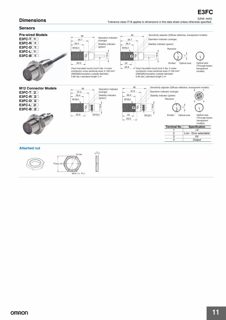
E3FCDimensions
Sensors
(Unit: mm)Tolerance class IT16 applies to dimensions in this data sheet unless otherwise specified.
35.7
23
29.9
48
16
.6
26.4
Operation indicator (orange)
Stability indicator (green)
M18×1
Sensitivity adjuster (Diffuse reflective, transparent models)
7
Receiver
Emitter Optical axis Optical axis(Through-beam, transparent models)
48
35.7
29.9
16
.6
26.4
Operation indicator (orange)
Stability indicator (green)M18×1
Vinyl insurated round cord 4 dia. 4 cores (conductor cross sectional area: 0.128 mm² (AWG26)/insulation outside diameter: 0.85 dia.) standard length 2 m
Vinyl insurated round cord 4 dia. 4 cores (conductor cross sectional area: 0.128 mm² (AWG26)/insulation outside diameter: 0.85 dia.) standard length 2 m
Pre-wired ModelsE3FC-T@1@E3FC-R@1@E3FC-D@1@E3FC-L@1@E3FC-B@1@
23
29,9
37,5
48
16
,6
26,4
M18x1
M12x1
Sensitivity adjuster (Diffuse reflective, transparent models)
Operation indicator (orange)
Stability indicator (green)
7
Receiver
Emitter Optical axis Optical axis (Through-beam, transparent models)
29,9
37,5
48
16
,6
26,4
M18x1
M12x1
Operation indicator (orange)
Stability indicator (green)
12
3 4
M12 Connector ModelsE3FC-T@2@E3FC-R@2@E3FC-D@2@E3FC-L@2@E3FC-B@2@
Terminal No. Specification1 +V2 L/on · D/on selectable3 0V4 Output
Three, 24
24 dia.
M18 4 P=1
4
Attached nut

E3FC
12
Accessories (Order Separately)
34
40.3
5259.9
2.7
8
1.6
7.57
Two, 3.5 dia.
3.5
3.85
8±0.
3
4.2 1
51.9
956 60
3436.95
41
ReflectorsE39-R1S E39-R50
72 63.680
44
Two, 3.5 dia.
Reflector
3
8.5
0.2
43
37
R4
15
Ø 3.2
reflective surface21.8 × 27.8 mm
5
30
E39-RP1 E39-R16
4.3
37
22
15
36.5
20
Two, 30°
Two, 4.3
Two, R15
42
1.5
90°(R16.5)
18.2 dia.
M18×1 4
Ø26
45°
Mounting bracketsE39-L183
Flush mounting nutE39-EL16
In the interest of product improvement, specifications are subject to change without notice.
ALL DIMENSIONS SHOWN ARE IN MILLIMETERS.
To convert millimeters into inches, multiply by 0.03937. To convert grams into ounces, multiply by 0.03527.
Terms and Conditions of Sale1. Offer; Acceptance. These terms and conditions (these "Terms") are deemed
part of all quotes, agreements, purchase orders, acknowledgments, price lists,catalogs, manuals, brochures and other documents, whether electronic or inwriting, relating to the sale of products or services (collectively, the "Products")by Omron Electronics LLC and its subsidiary companies (“Omron”). Omronobjects to any terms or conditions proposed in Buyer’s purchase order or otherdocuments which are inconsistent with, or in addition to, these Terms.
2. Prices; Payment Terms. All prices stated are current, subject to change with-out notice by Omron. Omron reserves the right to increase or decrease priceson any unshipped portions of outstanding orders. Payments for Products aredue net 30 days unless otherwise stated in the invoice.
3. Discounts. Cash discounts, if any, will apply only on the net amount of invoicessent to Buyer after deducting transportation charges, taxes and duties, and willbe allowed only if (i) the invoice is paid according to Omron’s payment termsand (ii) Buyer has no past due amounts.
4. Interest. Omron, at its option, may charge Buyer 1-1/2% interest per month orthe maximum legal rate, whichever is less, on any balance not paid within thestated terms.
5. Orders. Omron will accept no order less than $200 net billing. 6. Governmental Approvals. Buyer shall be responsible for, and shall bear all
costs involved in, obtaining any government approvals required for the impor-tation or sale of the Products.
7. Taxes. All taxes, duties and other governmental charges (other than generalreal property and income taxes), including any interest or penalties thereon,imposed directly or indirectly on Omron or required to be collected directly orindirectly by Omron for the manufacture, production, sale, delivery, importa-tion, consumption or use of the Products sold hereunder (including customsduties and sales, excise, use, turnover and license taxes) shall be charged toand remitted by Buyer to Omron.
8. Financial. If the financial position of Buyer at any time becomes unsatisfactoryto Omron, Omron reserves the right to stop shipments or require satisfactorysecurity or payment in advance. If Buyer fails to make payment or otherwisecomply with these Terms or any related agreement, Omron may (without liabil-ity and in addition to other remedies) cancel any unshipped portion of Prod-ucts sold hereunder and stop any Products in transit until Buyer pays allamounts, including amounts payable hereunder, whether or not then due,which are owing to it by Buyer. Buyer shall in any event remain liable for allunpaid accounts.
9. Cancellation; Etc. Orders are not subject to rescheduling or cancellationunless Buyer indemnifies Omron against all related costs or expenses.
10. Force Majeure. Omron shall not be liable for any delay or failure in deliveryresulting from causes beyond its control, including earthquakes, fires, floods,strikes or other labor disputes, shortage of labor or materials, accidents tomachinery, acts of sabotage, riots, delay in or lack of transportation or therequirements of any government authority.
11. Shipping; Delivery. Unless otherwise expressly agreed in writing by Omron:a. Shipments shall be by a carrier selected by Omron; Omron will not drop ship
except in “break down” situations.b. Such carrier shall act as the agent of Buyer and delivery to such carrier shall
constitute delivery to Buyer;c. All sales and shipments of Products shall be FOB shipping point (unless oth-
erwise stated in writing by Omron), at which point title and risk of loss shallpass from Omron to Buyer; provided that Omron shall retain a security inter-est in the Products until the full purchase price is paid;
d. Delivery and shipping dates are estimates only; ande. Omron will package Products as it deems proper for protection against nor-
mal handling and extra charges apply to special conditions.12. Claims. Any claim by Buyer against Omron for shortage or damage to the
Products occurring before delivery to the carrier must be presented in writingto Omron within 30 days of receipt of shipment and include the original trans-portation bill signed by the carrier noting that the carrier received the Productsfrom Omron in the condition claimed.
13. Warranties. (a) Exclusive Warranty. Omron’s exclusive warranty is that theProducts will be free from defects in materials and workmanship for a period oftwelve months from the date of sale by Omron (or such other period expressedin writing by Omron). Omron disclaims all other warranties, express or implied.(b) Limitations. OMRON MAKES NO WARRANTY OR REPRESENTATION,EXPRESS OR IMPLIED, ABOUT NON-INFRINGEMENT, MERCHANTABIL-
ITY OR FITNESS FOR A PARTICULAR PURPOSE OF THE PRODUCTS.BUYER ACKNOWLEDGES THAT IT ALONE HAS DETERMINED THAT THEPRODUCTS WILL SUITABLY MEET THE REQUIREMENTS OF THEIRINTENDED USE. Omron further disclaims all warranties and responsibility ofany type for claims or expenses based on infringement by the Products or oth-erwise of any intellectual property right. (c) Buyer Remedy. Omron’s sole obli-gation hereunder shall be, at Omron’s election, to (i) replace (in the formoriginally shipped with Buyer responsible for labor charges for removal orreplacement thereof) the non-complying Product, (ii) repair the non-complyingProduct, or (iii) repay or credit Buyer an amount equal to the purchase price ofthe non-complying Product; provided that in no event shall Omron be responsi-ble for warranty, repair, indemnity or any other claims or expenses regardingthe Products unless Omron’s analysis confirms that the Products were prop-erly handled, stored, installed and maintained and not subject to contamina-tion, abuse, misuse or inappropriate modification. Return of any Products byBuyer must be approved in writing by Omron before shipment. Omron Compa-nies shall not be liable for the suitability or unsuitability or the results from theuse of Products in combination with any electrical or electronic components,circuits, system assemblies or any other materials or substances or environ-ments. Any advice, recommendations or information given orally or in writing,are not to be construed as an amendment or addition to the above warranty.See http://www.omron247.com or contact your Omron representative for pub-lished information.
14. Limitation on Liability; Etc. OMRON COMPANIES SHALL NOT BE LIABLEFOR SPECIAL, INDIRECT, INCIDENTAL, OR CONSEQUENTIAL DAMAGES,LOSS OF PROFITS OR PRODUCTION OR COMMERCIAL LOSS IN ANYWAY CONNECTED WITH THE PRODUCTS, WHETHER SUCH CLAIM ISBASED IN CONTRACT, WARRANTY, NEGLIGENCE OR STRICT LIABILITY.Further, in no event shall liability of Omron Companies exceed the individualprice of the Product on which liability is asserted.
15. Indemnities. Buyer shall indemnify and hold harmless Omron Companies andtheir employees from and against all liabilities, losses, claims, costs andexpenses (including attorney's fees and expenses) related to any claim, inves-tigation, litigation or proceeding (whether or not Omron is a party) which arisesor is alleged to arise from Buyer's acts or omissions under these Terms or inany way with respect to the Products. Without limiting the foregoing, Buyer (atits own expense) shall indemnify and hold harmless Omron and defend or set-tle any action brought against such Companies to the extent based on a claimthat any Product made to Buyer specifications infringed intellectual propertyrights of another party.
16. Property; Confidentiality. Any intellectual property in the Products is the exclu-sive property of Omron Companies and Buyer shall not attempt to duplicate itin any way without the written permission of Omron. Notwithstanding anycharges to Buyer for engineering or tooling, all engineering and tooling shallremain the exclusive property of Omron. All information and materials suppliedby Omron to Buyer relating to the Products are confidential and proprietary,and Buyer shall limit distribution thereof to its trusted employees and strictlyprevent disclosure to any third party.
17. Export Controls. Buyer shall comply with all applicable laws, regulations andlicenses regarding (i) export of products or information; (iii) sale of products to“forbidden” or other proscribed persons; and (ii) disclosure to non-citizens ofregulated technology or information.
18. Miscellaneous. (a) Waiver. No failure or delay by Omron in exercising any rightand no course of dealing between Buyer and Omron shall operate as a waiverof rights by Omron. (b) Assignment. Buyer may not assign its rights hereunderwithout Omron's written consent. (c) Law. These Terms are governed by thelaw of the jurisdiction of the home office of the Omron company from whichBuyer is purchasing the Products (without regard to conflict of law princi-ples). (d) Amendment. These Terms constitute the entire agreement betweenBuyer and Omron relating to the Products, and no provision may be changedor waived unless in writing signed by the parties. (e) Severability. If any provi-sion hereof is rendered ineffective or invalid, such provision shall not invalidateany other provision. (f) Setoff. Buyer shall have no right to set off any amountsagainst the amount owing in respect of this invoice. (g) Definitions. As usedherein, “including” means “including without limitation”; and “Omron Compa-nies” (or similar words) mean Omron Corporation and any direct or indirectsubsidiary or affiliate thereof.
Certain Precautions on Specifications and Use1. Suitability of Use. Omron Companies shall not be responsible for conformity
with any standards, codes or regulations which apply to the combination of theProduct in the Buyer’s application or use of the Product. At Buyer’s request,Omron will provide applicable third party certification documents identifyingratings and limitations of use which apply to the Product. This information byitself is not sufficient for a complete determination of the suitability of the Prod-uct in combination with the end product, machine, system, or other applicationor use. Buyer shall be solely responsible for determining appropriateness ofthe particular Product with respect to Buyer’s application, product or system.Buyer shall take application responsibility in all cases but the following is anon-exhaustive list of applications for which particular attention must be given:(i) Outdoor use, uses involving potential chemical contamination or electricalinterference, or conditions or uses not described in this document.(ii) Use in consumer products or any use in significant quantities. (iii) Energy control systems, combustion systems, railroad systems, aviationsystems, medical equipment, amusement machines, vehicles, safety equip-ment, and installations subject to separate industry or government regulations. (iv) Systems, machines and equipment that could present a risk to life or prop-erty. Please know and observe all prohibitions of use applicable to this Prod-uct. NEVER USE THE PRODUCT FOR AN APPLICATION INVOLVING SERIOUSRISK TO LIFE OR PROPERTY OR IN LARGE QUANTITIES WITHOUTENSURING THAT THE SYSTEM AS A WHOLE HAS BEEN DESIGNED TO
ADDRESS THE RISKS, AND THAT THE OMRON’S PRODUCT IS PROP-ERLY RATED AND INSTALLED FOR THE INTENDED USE WITHIN THEOVERALL EQUIPMENT OR SYSTEM.
2. Programmable Products. Omron Companies shall not be responsible for theuser’s programming of a programmable Product, or any consequence thereof.
3. Performance Data. Data presented in Omron Company websites, catalogsand other materials is provided as a guide for the user in determining suitabil-ity and does not constitute a warranty. It may represent the result of Omron’stest conditions, and the user must correlate it to actual application require-ments. Actual performance is subject to the Omron’s Warranty and Limitationsof Liability.
4. Change in Specifications. Product specifications and accessories may bechanged at any time based on improvements and other reasons. It is our prac-tice to change part numbers when published ratings or features are changed,or when significant construction changes are made. However, some specifica-tions of the Product may be changed without any notice. When in doubt, spe-cial part numbers may be assigned to fix or establish key specifications foryour application. Please consult with your Omron’s representative at any timeto confirm actual specifications of purchased Product.
5. Errors and Omissions. Information presented by Omron Companies has beenchecked and is believed to be accurate; however, no responsibility is assumedfor clerical, typographical or proofreading errors or omissions.

OMRON CANADA, INC. • HEAD OFFICEToronto, ON, Canada • 416.286.6465 • 866.986.6766 • www.omron247.com
OMRON ELECTRONICS DE MEXICO • HEAD OFFICEMéxico DF • 52.55.59.01.43.00 • 01-800-226-6766 • [email protected]
OMRON ELECTRONICS DE MEXICO • SALES OFFICEApodaca, N.L. • 52.81.11.56.99.20 • 01-800-226-6766 • [email protected]
OMRON ELETRÔNICA DO BRASIL LTDA • HEAD OFFICESão Paulo, SP, Brasil • 55.11.2101.6300 • www.omron.com.br
OMRON ARGENTINA • SALES OFFICECono Sur • 54.11.4783.5300
OMRON CHILE • SALES OFFICESantiago • 56.9.9917.3920
OTHER OMRON LATIN AMERICA SALES54.11.4783.5300
Authorized Distributor:
E65I-E-02 12/14 Note: Specifications are subject to change. © 2014 Omron Electronics LLC Printed in U.S.A.
Printed on recycled paper.
Automation Control Systems• Machine Automation Controllers (MAC) • Programmable Controllers (PLC) • Operator interfaces (HMI) • Distributed I/O • Software
Drives & Motion Controls • Servo & AC Drives • Motion Controllers & Encoders
Temperature & Process Controllers • Single and Multi-loop Controllers
Sensors & Vision• Proximity Sensors • Photoelectric Sensors • Fiber-Optic Sensors• Amplified Photomicrosensors • Measurement Sensors• Ultrasonic Sensors • Vision Sensors
Industrial Components • RFID/Code Readers • Relays • Pushbuttons & Indicators• Limit and Basic Switches • Timers • Counters • Metering Devices • Power Supplies
Safety • Laser Scanners • Safety Mats • Edges and Bumpers • Programmable Safety Controllers • Light Curtains • Safety Relays • Safety Interlock Switches
OMRON AUTOMATION AND SAFETY • THE AMERICAS HEADQUARTERS • Chicago, IL USA • 847.843.7900 • 800.556.6766 • www.omron247.com
OMRON EUROPE B.V. • Wegalaan 67-69, NL-2132 JD, Hoofddorp, The Netherlands. • +31 (0) 23 568 13 00 • www.industrial.omron.eu