PHOTOCATALYTIC MEMBRANES FOR VIRUS … MEMBRANES FOR VIRUS INACTIVATION By ... span compared with...
74
PHOTOCATALYTIC MEMBRANES FOR VIRUS INACTIVATION By Brian J. Starr A THESIS Submitted to Michigan State University in partial fulfillment of the requirements for the degree of Environmental Engineering – Master of Science 2015
Transcript of PHOTOCATALYTIC MEMBRANES FOR VIRUS … MEMBRANES FOR VIRUS INACTIVATION By ... span compared with...

PHOTOCATALYTIC MEMBRANES FOR VIRUS
INACTIVATION
By
Brian J. Starr
A THESIS
Submitted to
Michigan State University
in partial fulfillment of the requirements
for the degree of
Environmental Engineering – Master of Science
2015
ABSTRACT
PHOTOCATALYTIC MEMBRANES FOR VIRUS INACTIVATION
By
Brian J. Starr
Porous ceramic membranes are ideal candidates for use in environmental treatment and
remediation. Ceramic membranes have a high chemical and thermal stability, allowing for
aggressive cleaning and increased life span compared with polymeric membranes. For the same
reasons, they are often used as substrates in photocatalytic membrane reactors. A multitude of
techniques have been proposed to fabricate these photocatalytic membranes. In this study,
Layer-by-layer self-assembly (LbL) and plasma enhanced chemical vapor deposition (PECVD)
were used to create photocatalytic TiO2 coatings on the support structure of ceramic disc
microfiltration membranes. The resulting photocatalytic layers did not measurably reduce the
membrane permeability. The LbL coated membrane degraded methylene blue at a higher rate
compared to the PECVD coated membrane during UV filtration experiments. By assuming a
plug flow reactor (PFR) model and normalizing the measured PFR rate constant by the catalytic
efficiency of each catalyst, it is evident the LbL fabricated membrane benefited from the high
catalytic efficiency of the Degussa P25 photocatalyst. Additionally, the LbL fabricated
membrane’s efficiency at inactivating MS2 and P22 bacteriophages was tested. While P22 was
inactivated at a higher rate in batch reactors, MS2 was more susceptible to inactivation during
UV dead-end filtration, with a maximum log removal value (LRV) of 4.9 achieved at the flow
rate of 4x10⁻³ liters per minute for MS2 and only 1.6 LRV of P22 at the lower flow rate 3x10⁻³
liters per minute. With the coating on the permeate side of the membrane, this approach to virus
inactivation is particularly promising in applications to waters with high degree of turbidity.
iii
ACKNOWLEGMENTS
Thanks to Craig Burck from The Department of Civil and Environmental Engineering at
Michigan State University for his assistance in constructing the UV dead-end filtration cell.
Becca Ives and Daniel Ginsburg from The Water Quality and Environmental Microbiology
Laboratory at Michigan State Universe for their assistance with culturing bacteriophages. Ghada
Jamal, Stephanie Roualdes, and Andre Ayral at the European Institute of Membranes allowing
use of their PECVD coating equipment and providing valuable guidance. My advisor,
Volodymyr Tarabara, from The Department of Civil and Environmental Engineering at
Michigan State University, for his continued support and direction throughout my graduate
studies at Michigan State University.

iv
TABLE OF CONTENTS
LIST OF TABLES ......................................................................................................................... vi
LIST OF FIGURES ...................................................................................................................... vii
CHAPTER 1 ................................................................................................................................... 1 1.1 Introduction to titanium dioxide, photocatalytic reactions, and photocatalytic processes .................. 1 1.2 Ceramic Membranes ........................................................................................................................... 4 1.3 Catalyst-membrane configuration ....................................................................................................... 8
1.4 Membrane-catalyst coating techniques ..................................................................................... 11
1.5 Photocatalytic Membrane Applications ............................................................................................ 13
REFERENCES ....................................................................................................................................... 18
CHAPTER 2 ................................................................................................................................. 25 2.1 Introduction ....................................................................................................................................... 25
2.2 Approach ........................................................................................................................................... 28 2.2.1 Fabrication of photoactive membrane layer ........................................................................ 28
2.2.2 Important elements of photocatalytic membrane layers ....................................................... 29
2.3 Experimental ..................................................................................................................................... 33 2.3.1 Reagents.......................................................................................................................... 33
2.3.2 LbL assembly .................................................................................................................. 33
2.3.3 Plasma enhanced chemical vapor deposition ...................................................................... 35
2.3.4 Batch experiments ............................................................................................................ 36
2.3.5 Dead-end filtration experiments ........................................................................................ 36
2.3.6 Measuring concentration of Methylene Blue ...................................................................... 39
2.3.7 UV fluence quantification ................................................................................................. 39
2.3.8 Scanning electron microscope imaging .............................................................................. 40
2.4 Results and Discussion ..................................................................................................................... 40 2.4.1 Titanium dioxide LbL assembly characterization ............................................................... 41
2.4.2 Batch experiments on photocatalytic oxidation of methylene blue ....................................... 44
2.4.3 LbL and PECVD layer permeability .................................................................................. 46
2.4.4 UV MB dead-end filtration and analysis ............................................................................ 48
2.5 Conclusion ........................................................................................................................................ 53 REFERENCES ....................................................................................................................................... 54
CHAPTER 3 ................................................................................................................................. 57
3.1 Introduction ....................................................................................................................................... 57 3.2 Experimental ..................................................................................................................................... 58
3.2.1 Reagents.......................................................................................................................... 58
3.2.2 Batch Experiments ........................................................................................................... 58
3.2.3 Dead-end filtration experiments ........................................................................................ 59
3.2.4 Quantification of bacteriophage concentration ................................................................... 60
3.3 Results and Discussion ..................................................................................................................... 61
3.3.1 Bacteriophage batch experiments ...................................................................................... 61

v
3.3.2 UV Bacteriophage dead-end filtration ............................................................................... 63 3.4 Conclusion ........................................................................................................................................ 65 REFERENCES ....................................................................................................................................... 66
vi
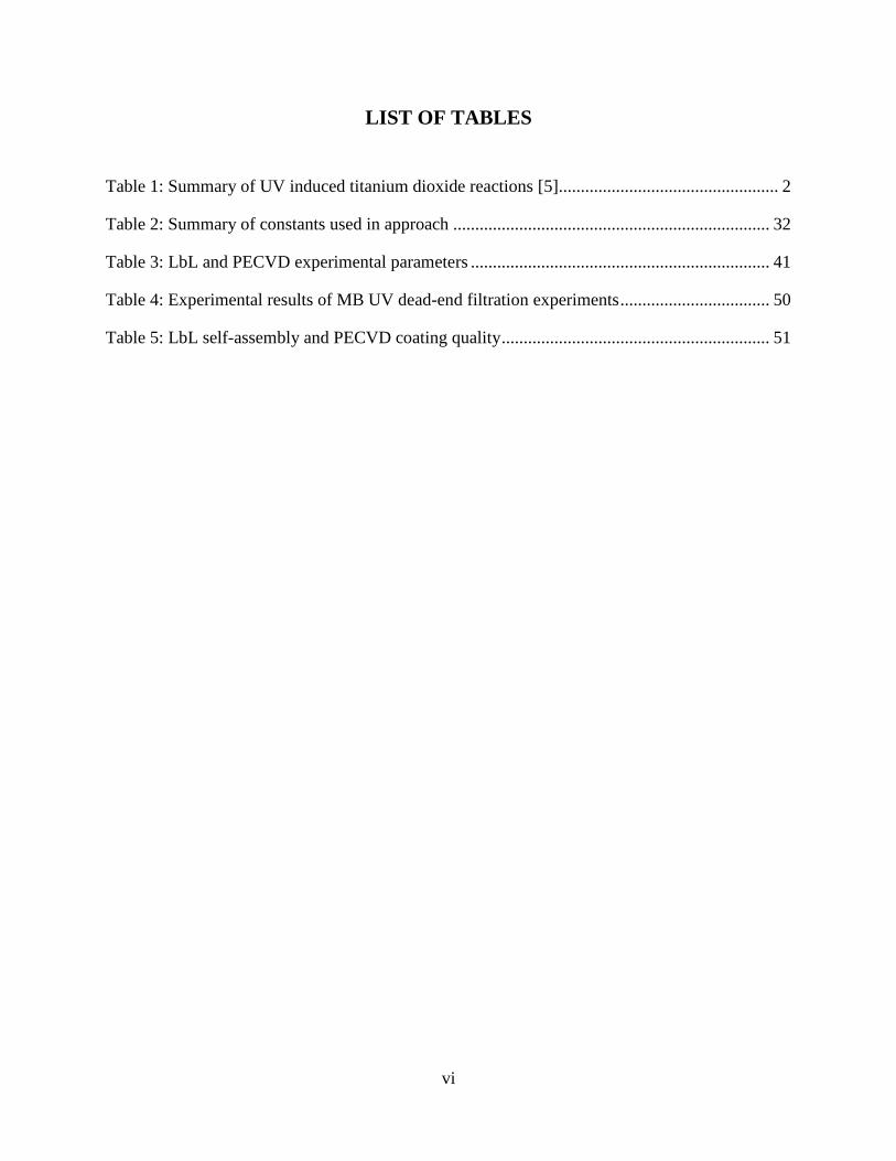
LIST OF TABLES
Table 1: Summary of UV induced titanium dioxide reactions [5] .................................................. 2
Table 2: Summary of constants used in approach ........................................................................ 32
Table 3: LbL and PECVD experimental parameters .................................................................... 41
Table 4: Experimental results of MB UV dead-end filtration experiments .................................. 50
Table 5: LbL self-assembly and PECVD coating quality ............................................................. 51

vii
LIST OF FIGURES
Figure 1: Photocatalytic membrane configurations A) Selective layer coating B) Coupled
photoactive-selective layer C) Support coating D) Embedded coating .......................................... 9
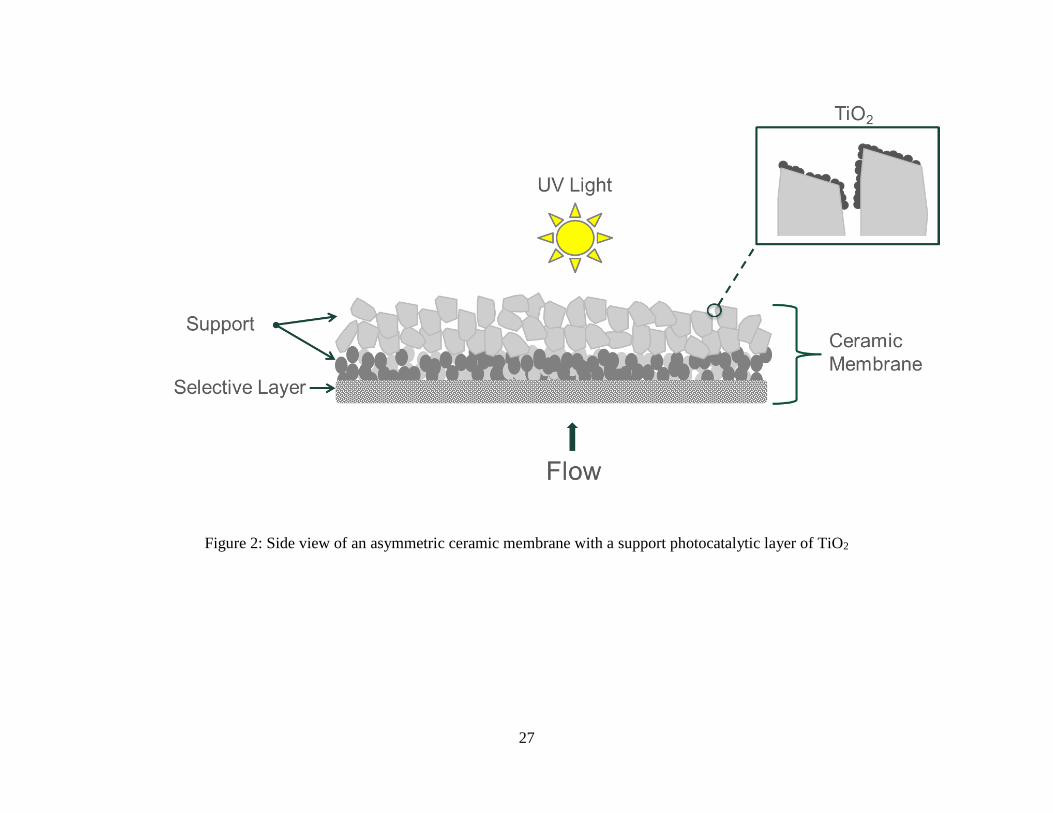
Figure 2: Side view of an asymmetric ceramic membrane with a support photocatalytic layer of
TiO2 ............................................................................................................................................... 27
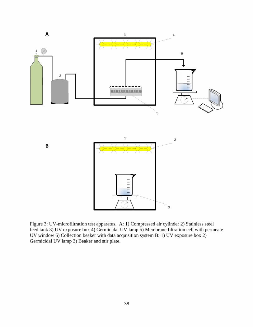
Figure 3: UV-microfiltration test apparatus. A: 1) Compressed air cylinder 2) Stainless steel
feed tank 3) UV exposure box 4) Germicidal UV lamp 5) Membrane filtration cell with permeate
UV window 6) Collection beaker with data acquisition system B: 1) UV exposure box 2)
Germicidal UV lamp 3) Beaker and stir plate. ............................................................................. 38
Figure 4: SEM images of LbL assembly of TiO2 nanoparticles on glass slides: A)
(PAH+PSS)+TiO2; B) (PDADMAC+PAA)4+TiO2 with catalyst in 0.01 M ionic strength
solution; C) (PDADMAC+PAA)4+TiO2 with PAA and TiO2 pH 2.5; D)
(PDADMAC+PAA)4+TiO2 with PAA and TiO2 pH 5; E) (PDADMAC+PAA)4+TiO2 using high
power probe sonicator; F) (PDADMAC+PAA)4+TiO2 using bath sonicator. .............................. 43
Figure 5: SEM images of (PDADMAC+PAA)4+TiO2 coated ceramic membranes .................... 44
Figure 6: MB batch experiments with A) 10 mg/L Degussa P25 catalyst B) 17 mg/L PECVD
generated catalyst .......................................................................................................................... 46
Figure 7: Clean water flux tests with photocatalytic 0.14 μm membranes A) 5-layer LbL; B) 1-
layer PECVD; C) 2-layer PECVD. ............................................................................................... 47
Figure 8: MB UV dead-end filtration experiments A) 0.14 µm, 1 layer PECVD B) 0.14 µm 2
layers PECVD C) 0.14 µm, 5-layer LbL ...................................................................................... 49
Figure 9: Comparison of Photocatalytic Coatings A) Reactive flux B) Θxlx/Θyly, where x is the
coating used in the column and y is the PECVD coating with 2 layers........................................ 52
Figure 10: Bacteriophage batch testing using 1.25 mg/L Degussa P25 photocatalyst: A) MS2; B)
P22 ................................................................................................................................................ 62
Figure 11: UV dead-end filtration experiments A) MS2 B) P22 .................................................. 64
1
CHAPTER 1
A review of titanium dioxide photocatalytic ceramic membranes
Titanium dioxide photocatalytic properties, related reactions, and photocatalytic treatment
processes are reviewed in section 1.1. Section 1.2 highlights ceramic membrane fabrication
techniques and research aimed at reducing costs of manufacturing membranes. Sections 1.3-1.5
discuss photocatalytic membrane processes, fabrication of photocatalytic membranes, and their
application to water treatment.
1.1 Introduction to titanium dioxide, photocatalytic reactions, and
photocatalytic processes
Titanium dioxide is a semiconducting metal capable of splitting water [1]. With irradiation from
UV light, it has been widely shown to generate reactive oxygen species, including •OH and O2−
[2-4]. The chain reactions necessary to generate these reactive species are summarized in Table
1 [5]. The reactions are initiated when UV light, with a wavelength less than 400 nm, excites
electrons from the valence band (vb) to the conduction band (cb). This excitation leaves a
reactive hole where the electron was previously located. The excited electron and reactive hole
combine with bonded TiO2 to migrate the reactive species to the crystal surface and delay
recombination; these reactions are referred to as traps. In the presences of oxygen species, the
trapped electron can combine with O2 to create superoxide radicals and the reactive hole can
combine with hydroxyl ions to create hydroxyl radicals. These species can then go on to create

2
other reactive oxygen species (ROS) or react with an organic contaminant. Additionally, the
electron may return to the valence band and not result in a reaction.
Table 1: Summary of UV induced titanium dioxide reactions [5]
Reaction Description
𝑇𝑖𝑂2 + 𝑈𝑉 → 𝑒− + ℎ𝑜𝑙𝑒+ Electron excitation and hole creation
𝑒𝑐𝑏− → 𝑒𝑡𝑟
− & ℎ𝑜𝑙𝑒𝑣𝑏 → ℎ𝑜𝑙𝑒𝑡𝑟 Electron and hole trapping
𝑒𝑡𝑟− + ℎ𝑜𝑙𝑒𝑡𝑟 → 𝑒𝑐𝑏
− + ℎ𝑒𝑎𝑡 Electron hole recombination
𝑂2 + 𝑒𝑡𝑟− → 𝑂2
∗− Superoxide radical formation
𝑂𝐻− + ℎ𝑜𝑙𝑒𝑡𝑟 → 𝑂𝐻∗ Hydroxyl radical formation
𝑂𝑟𝑔𝑎𝑛𝑖𝑐𝑠 + 𝑇𝑖𝑂2 → 𝐶𝑂2 + 𝐻2𝑂 Overall reaction of organic pollutant and
TiO2 results in mineralization
Significant research has been aimed at exploiting these pathways for the degradation of organic
pollutants and inactivation of pathogens in water treatment [6-8]. Compared with chemical
disinfection and oxidation, photocatalysis with TiO2 produces significantly fewer disinfection
byproducts (DBP) [9]. Additionally, TiO2 has the ability to degrade DBP precursors that are
present, resulting in fewer produced DBPs when TiO2 disinfection is combined with chlorine [9].
Titanium dioxide generally exists in any of four phases; amorphous, brookite, anatase, and rutile,
with anatase and rutile the most commonly generated crystallinity [10]. The crystallinity of TiO2
can be altered by adjusting the catalyst preparation parameters, such as the sintering temperature
[11]. As reviewed by Ismail and Bahnemann, anatase crystallinity is often the objective when
generating TiO2 photocatalyst, due to its high photoactivity [12]. This is not true for all
3
reactions, as Tay found brookite to be more productive in generating H2 than anatase [10].
Interestingly, Bacsa and Kiwi showed that pure anatase was less photoactive than a mixture of
rutile and anatase [13]. From their experimental work a ratio of 70% anatase to 30% rutile was
more efficient than Degussa P25, a highly efficient TiO2 catalyst. A similar result was obtained
by Bakardjeiva et at, who found 100% anatase exhibited poorer photodegradation of 4-
chlorophenol, while a mixture of ~77% anatase and 33% rutile enhanced degradation [14].
Lastly, the lower surface areas, due to elevated calcination temperatures, associated with rutile
may account for its lower apparent catalytic efficiency [15]. A direct comparison on the inherent
catalytic properties of rutile and anatase must account these physical changes, as well as
differences in the crystal phase composition.
Degussa P25, is a commercially available TiO2 nanoparticle often cited as a standard for high
photoactivity [14]. It is frequently reported as a simple mixture of anatase and rutile crystallinity
[16, 17]. Further investigation has shown that although the XRD graphs of P25 and simple
mixtures of pure anatase and pure rutile are similar, images with TEM show that P25 contains
complicated amorphous/anatase and amorphous/rutile regions, that are not present in the simple
mixtures [18]. The high photoactivity of P25 has been attributed to these complicated multi-
crystalline regions. More recently, this finding was contradicted by Ohtani [19], who found the
phases did not interact and suggests there is no evidence of a synergism between the mixed
phases.
Metal doping of titanium dioxide is an active area of research in photocatalysis. Various benefits
have been seen, such as improved bacterial disinfection with Ag-TiO2 membranes [20] and
increased visible light photoactivity with nickel [21]. Experiments testing a multitude of M-TiO2
coatings under visible light have demonstrated that improved reaction kinetics are often pollutant

4
specific [22]. Interestingly, metal doping TiO2 has been shown to change the anatase-rutile
phase conversion temperature. Specifically, ruthenium inhibited the conversion from anatase to
rutile up to 700°C [22]. This can become important in photocatalytic membrane fabrication
techniques that require high sintering temperatures, such as hollow fiber fabrication.
Photocatalytic processes using TiO2 are generally implemented by either suspending the TiO2 in
a photoreactor or immobilizing it on the surface of a contactor [23]. Suspended reactors have the
benefit of higher TiO2 loading, but require an additional process unit for photocatalyst recovery
[24]. Immobilized TiO2 reactors have lower catalyst loadings, but do not require catalyst
recovery [24].
Immobilized photocatalytic processes require a contactor. Contactors can take various
geometries, such as the smooth surface of a reaction vessel [26] or porous particles [27].
Properties of contactors include high surface area, chemical and thermal stability, and ease of
cleaning. With the addition of a separation layer, a porous contactor may also serve as a
membrane. Depending on where the catalyst is deposited, the use of a membrane as a contactor
provides several benefits to both the membrane and the photocatalytic processes, including
contaminant concentration on the catalyst, reduced turbidity for the improved efficiency of UV
light, and reduced membrane fouling. Due to their mechanical and chemical stability, ceramic
membranes are the most frequently used membrane contactors.
1.2 Ceramic Membranes
Inorganic membranes are available in a wide variety of materials, geometries, and
configurations. Due to their chemical and thermal stability, inorganic membranes are often used
5
in processes with demanding conditions that justify their additional cost compared to polymeric
membranes. Inorganic membranes can be made of oxide, metal, carbon, or other materials [28].
Commonly available geometries include disk and tubular [29]. Multi-channel tubular
membranes, referred to as monoliths, are commercially available and provide an increased
surface area density [29]. Inorganic membranes can be porous or dense. The pore size cutoff
between porous and dense is not precisely defined, but dense inorganic membranes are used in
gas phase separation processes, whereas porous inorganics are used in water treatment. This
review will focus on porous ceramic membranes, which are suitable for use as photocatalytic
contactors and in water treatment processes.
Porous ceramic membranes are typically asymmetrical and can be defined by several layers. The
active layer has the smallest pore size and performs the separative process. This layer is
typically made very thin to reduce its hydraulic resistance. The outer layers have increasingly
larger pore sizes and act to support the thin active layer. Slip casting, tape casting, pressing, and
extrusion are all methods used to fabricate support structures [30]. The active layer is typically
formed via advanced techniques, such as sol-gel precipitation, chemical vapor deposition, or dip
coating [30].
In slip casting, tape casting, and pressing methods a pliable paste of ceramic particles is formed
into a solid structure by removing solvent from the paste. This structure is then dried and
sintered to create a stable support. During slip casting, the ceramic paste is applied to a porous
mold and capillary forces remove the solvent. The tape casting process uses a casting knife to
deposit a film of suspended ceramic and the solvent is removed by evaporation. Pressing
techniques use force to remove the solvent. Extrusion methods force a plastic-like paste through
a nozzle to give it shape. When force is not being applied, the paste has increased rigidity.

6
When forming the active layer using sol-gel processes, a solution of ceramic precursor is applied
to a support structure and ceramic is then precipitated on the surface. This process has higher
control of pore size, porosity, and film thickness than the casting and pressing methods. With
dip coating, a substrate is submersed in a suspension of ceramic particles. The layers morphology
can be adjusted by varying the suspension viscosity, contact time, and dipping speed. Chemical
vapor deposition uses a carrier gas to bring a flux of precursor to a substrates surface. A reaction
then occurs either in the gas phase or on the substrate itself, resulting in a thin film of deposited
ceramic.
Active research in ceramic membrane fabrication focuses on improving the stability of the
membranes [31-32], separative functionality [33-34], and/or reducing manufacturing costs [35-
36]. While stability is a critical property in processes such as high temperature flue gas
treatment, membranes in water treatment are not typically exposed to such extreme conditions.
Research on improving ceramic membrane separative functionality centers on dense membrane
fabrication, often for gas separation. In water treatment, which uses porous membranes,
important research to allow widespread application is centered on reducing manufacturing cost.
Major costs associated with ceramic membrane fabrication are expensive precursor materials
such as alumina, zirconia, titania, and silica and the energy intensive sintering process [37].
Sintering is an additional cost that polymeric membrane fabrication does not require. Lower cost
materials, such as clay, sawdust, fly ash, calcium carbonate, and quartz have all been
successfully used in creating ceramic membranes. New low cost ceramic membrane fabrication
techniques blend a selection of these precursors in order to create a stable porous membrane.
Clay is used for its low plasticity and high refractory properties [38]. Calcium carbonate is often
used as a pore former [39]. Quartz or similar materials add strength to the membrane [38]. Fly

7
ash is a readily available byproduct of the coal industry and serves as a filler material.
Membranes utilizing fly ash require binders, such as polyvinyl alcohol [40].
In effort to make ceramic technologies more affordable, recent research has shown ceramic
membranes can be fabricated using locally available natural materials. Belibi et al. fabricated a
microfiltration membrane using only Cameroonian clay, with sawdust as a pore former [40].
Wang et al. developed microfiltration membranes using a mix of Portland cement and quartz,
which did not require any sintering [42].
Membranes fabricated with low cost materials are typically prepared by uniaxial wet or dry
compaction or the paste methodology. In the paste method, the precursors are simply mixed with
a small amount of water, placed in a mold, slowly dried, and then sintered [37]. In the
compaction method, similar to conventional ceramic membrane support fabrication, the
precursors are homogenously mixed with or without water, pressed with mechanical force, and
sintered [39]. A comparison between the two methods showed that uniaxial compaction resulted
in larger pore sizes compared with the paste method, even with the same precursor formulation
[39]. Vasanth et al. has shown these fabrication techniques can produce a ceramic membrane for
approximately $61 per square meter compared to $500 per square meter for a similar ceramic
alumina membrane.
Low cost ceramics have been successfully applied in bacterial separation [36], oil-water
separation [39], and food processing [43]. Further testing is needed to understand the chemical
and thermal stability of these low cost membranes. Only one of the above cited studies
investigated the mechanical strength and hydraulic stability [41], but as Buekenhoud [44]
reviewed, dynamic tests with corrosive fluids are needed to understand the true chemical stability
of these membranes.

8
1.3 Catalyst-membrane configuration
Photocatalytic membranes can be categorized into three groups based on the catalyst location;
membranes with selective layer coating, membranes with support coating, or embedded reactors.
Locating the photocatalyst on the selective layer is the most commonly reported configuration.
With this configuration (Figure 1A), there are several synergistic benefits to both the membrane
and photocatalytic process. During filtration, the pollutant is concentrated on the catalyst due to
the concentration polarization effect, resulting in faster reaction kinetics. The catalyst reaction
may also benefit the membrane separation process by degrading pollutants that cause fouling
[45]. Additionally, since titanium dioxide is hydrophilic, TiO2 coated selective layers have
shown increased water flux compared to uncoated membranes [46].
In order to reduce the hydraulic resistance of the coated membrane, research has been performed
into creating a dual-purpose selective and photoactive layer of TiO2, referred to as coupled
functionality. With these membranes, the catalyst layer acts as the mechanical barrier to
pollutants and is also the photoactive layer (Figure 1B). This eliminates the need for a separate
catalyst layer and selective layer. The primary drawback of coupled membranes is that the
separative functionality and photoactivity may have distinctly different optimized requirements.
For example, a 3 nm coupled TiO2 membrane produced by Wu et al. [11] had a molecular weight
cut off of 4,000 kDa, while they reported a commercially available non-photoactive membrane
with the same pore size made of silica/zirconia had a MWCO of just 1,000 kDa. This difference
was attributed to the more favorable interaction between the non-photoactive membrane material
and contaminants.

9
Figure 1: Photocatalytic membrane configurations A) Selective layer coating B) Coupled
photoactive-selective layer C) Support coating D) Embedded coating

10
Coating the membrane support (Figure 1C), has the benefit of allowing optimization of the
selective layer and photoactive layers independently. This process arrangement was first
proposed by Bosc et al. [47], though experimental results were not reported. Having the
photoactive layer on the outside of the membrane also allows for a simpler arrangement of
coupling between the source of UV irradiation and the photocatalytic surface, especially when
ceramic tubular membranes are employed. Also, the membrane will remove turbidity prior to
photocatalysis, improving catalytic performance through two mechanisms. First, the less turbid
water will allow for higher fluence on the catalyst. Second, the turbidity causing particles react
with reactive oxygen species, reducing the ROS concentration available for disinfection.
Literature on membrane support side coatings is limited. In one study [48], both the feed and
permeate side of a ceramic support were coated; the authors showed that both layers of TiO2
contributed to the degradation of a model pollutant.
The embedded reactor has catalyst coated or embedded throughout the matrix of the membrane
(Figure 1D.) In contrast to the previous configurations, catalyst is not limited to outer layers on
the feed or support side. Catalytic membrane reactors with this configuration are the most
commonly developed due to the increased pollutant-catalyst contact time. Since photocatalytic
reactions require catalyst exposure to UV light, photocatalytic membranes with this
configuration have seen limited development. An exception are photocatalytic membranes that
use photoactive catalyst as the only membrane material. Zhang et al. [16] created photocatalytic
hollow fibers through membrane spinning and phase inversion that resulted in pure TiO2 hollow
fibers. Due to their small size, hollow fibers have a high specific surface area, which is
beneficial to photocatalytic reactions and membrane separation. A significant limitation of this
technique is that photoactivity decreases with increasing sintering temperature while high

11
sintering temperatures are needed to give mechanical strength to the hollow fibers. In
permeability experiments the authors used hollow fiber membranes prepared with low
photoactivity due to the weak mechanical strength of the hollow fibers with high photoactivity.
Similar to the dual-functionality membranes, the photoactive and membrane separation function
need to optimize simultaneously, which may be a challenge.
1.4 Membrane-catalyst coating techniques
Methods of fabrication of photocatalytic membranes can be divided broadly into two groups of
techniques: 1) deposition of existing (pre-formed) nanoparticles on the membrane and 2) the use
of TiO2 precursors to precipitate photocatalyst on the membrane. When using existing
nanoparticles, they are typically suspended in solution and the substrate is coated using a dip
coating procedure [49-50]. This has the benefit of simple assembly techniques and the known
high photoactivity of the particle, such as Degussa P25 [51]. The drawback is that the particles
may not be optimally placed on the membrane, resulting in a significant reduction in flux [52].
In dip coating, high concentrations of particles are suspended, often with the aid of a dispersant
[49]. A substrate is then dipped in the catalyst suspension and withdrawn at a constant rate. The
deposited film thickness is dependent on withdrawal speed, suspension viscosity, evaporation
rate, and substrate width [53].
Similar to dip coating, LbL self-assembly is a simple method that has been used to create thin
films from existing nanoparticles. In LbL self-assembly, polyelectrolytes are coated on a
substrate, resulting in a modification of the surface charge characteristics. The polyelectrolyte
coated substrate is then submersed in a low concentration nanoparticle suspension.
12
Nanoparticles adhere to the polyelectrolytes via electrostatic interactions. LbL self-assembly can
be completed by either two-step or three-step assembly. In three-step assembly, a substrate is
coated with multiple bilayers of alternatively charged polyelectrolytes [54]. The terminating
layer has the same charge as the substrate. The oppositely charged nanoparticles are then
adhered to this layer. In two-step assembly, a single polyelectrolyte is used [55]. LbL self-
assembly has been applied to non-photoactive catalytic membrane reactors. Dotzauer utilized
LbL self-assembly to create a catalytic wall reactor membrane with a sub-monolayer deposition
of gold particles on a polymeric membrane [56]. A review of literature could not find examples
of LbL self-assembly used in TiO2 photocatalytic membrane fabrication.
Using TiO2 precursors, TiO2 crystals have been formed in place on various membrane materials,
with the aim of improving flux, selectivity, photoactivity, or all of the above. Sol-gel dip coating
is a common technique that utilizes TiO2 precursors. Typically, a precursor, such as titanium
tetraisopropoxide (TTIP), is added to a solution containing surfactants and other reagents that
cause the TTIP to hydrolyze and form TiO2 [57]. The membrane is dipped into the sol, dried,
and then sintered. The surfactants structure the precursors. These organics are removed through
sintering, leaving an organized TiO2 structure.
Varying the surfactants and adding copolymers can create unique crystal structures, such as
cylindrical or hexagonal pores [47]. This technique is most beneficial for coupled selective and
photoactive coatings, allowing the pore size to be tuned by varying assembly conditions.
Additionally, varying the drying, stabilizing, and sintering temperature and duration can also
lead to structural changes [47]. The sol-gel dip coating procedure can be repeated, adjusting the
parameters to create a hierarchical structure with improve permeability compared to non-
hierarchical multilayers, while preserving photoactivity [58]. Non-selective nanostructures, such
13
as nano-ribbons and nano-wires, have been generated from TTIP precursors by controlling the
hydrolysis rate [52]. The authors found these coated membranes to have a significantly higher
permeability, while maintaining a similar photoactivity to a P25 coated membrane.
Chemical vapor deposition (CVD) has been used to deposit TiO2 films onto various porous
substrates, including alumina, activated carbon, and silica [27]. This technique has been
extended to produce photoactive TiO2 membranes [48]. Stated benefits of CVD are scalability,
reduced manufacturer costs, and improved permeability. Though comprehensive comparisons
on these metrics for dip coating, LbL self-assembly, sol-gel dip coating and CVD could not be
found in literature. One comparison study on the photoactivity found that both CVD and sol-gel
dip coating could produce equally high photoactivity [59]. A drawback of CVD is the high
temperature required during the deposition. The previously cited study uses temperatures up to
600°C during deposition. With the aid of plasma, the reactor temperature can be lowered to near
room temperature [60]. Plasma enhanced vapor deposition excites the TiO2 precursor in the
vapor phase into a plasma using R.F., causing the photocatalyst to then form on the substrate.
This reduces energy demand of the process and allows for coating on temperature sensitive
materials.
1.5 Photocatalytic Membrane Applications
Titanium dioxide photocatalytic membranes have many potential applications in water treatment,
including: mineralization of organic pollutants, improved membrane flux, and inactivation of
pathogens. There have been several proposed mechanisms for the increased flux of TiO2 coated
membranes, including increased hydrophilicity, reduced biofilm generation, and degradation of
14
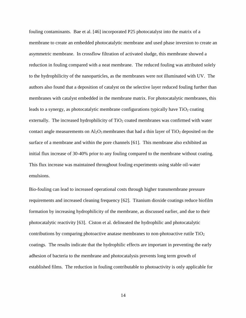
fouling contaminants. Bae et al. [46] incorporated P25 photocatalyst into the matrix of a
membrane to create an embedded photocatalytic membrane and used phase inversion to create an
asymmetric membrane. In crossflow filtration of activated sludge, this membrane showed a
reduction in fouling compared with a neat membrane. The reduced fouling was attributed solely
to the hydrophilicity of the nanoparticles, as the membranes were not illuminated with UV. The
authors also found that a deposition of catalyst on the selective layer reduced fouling further than
membranes with catalyst embedded in the membrane matrix. For photocatalytic membranes, this
leads to a synergy, as photocatalytic membrane configurations typically have TiO2 coating
externally. The increased hydrophilicity of TiO2 coated membranes was confirmed with water
contact angle measurements on Al2O3 membranes that had a thin layer of TiO2 deposited on the
surface of a membrane and within the pore channels [61]. This membrane also exhibited an
initial flux increase of 30-40% prior to any fouling compared to the membrane without coating.
This flux increase was maintained throughout fouling experiments using stable oil-water
emulsions.
Bio-fouling can lead to increased operational costs through higher transmembrane pressure
requirements and increased cleaning frequency [62]. Titanium dioxide coatings reduce biofilm
formation by increasing hydrophilicity of the membrane, as discussed earlier, and due to their
photocatalytic reactivity [63]. Ciston et al. delineated the hydrophilic and photocatalytic
contributions by comparing photoactive anatase membranes to non-photoactive rutile TiO2
coatings. The results indicate that the hydrophilic effects are important in preventing the early
adhesion of bacteria to the membrane and photocatalysis prevents long term growth of
established films. The reduction in fouling contributable to photoactivity is only applicable for

15
membranes with selective layer catalyst coatings, whereas membranes with only permeate side
surface coatings will not benefit from reduced fouling.
Both suspended and immobilized titanium dioxide has been investigated for application in
mineralizing organic pollutants [26]. As compared to traditional membrane processes,
photocatalytic treatment of organic pollutants mineralizes the pollutant, rather than concentrating
it. Photocatalytic membranes have been studied in this application, most commonly using dyes
as a model [49, 16]. One drawback photocatalytic membranes have is the limited contact time as
compared to suspended TiO2 reactors. Wang et al. found the maximum one pass decomposition
of Acid Red 4 dye to be about 65% for dead-end filtration, but this decreases rapidly with
increasing flowrate [49]. Similarly, Zhang et al. demonstrated an 82% removal of Direct Black
168 with TiO2 photocatalytic membrane, though this required an extended run time of 300
minutes [16]. For treatment of highly concentrated dyes, coating the membrane permeate side
may provide improved reaction kinetics from the increased UV fluence, due to reduced dye
concentration by the membrane. In addition to dyes, other organic pollutants have been tested.
Kovaleva et al have studied the removal of benzothiazoles [64], Molinari et al tested the
degradation of 4-nitrophenol with the use of polymeric photocatalytic membranes [65], and
Zhang removed sodium dodecylbenzene sulfonate with composite ceramic nano-rod membranes
[66].
Pharmaceutical and personal care products (PPCPs), such as 4-Methylbenzylidene Camphor and
Octocrylene, have been found to persist through conventional wastewater treatment processes
and be discharged to the environment [67]. Titanium dioxide photocatalytic membranes have
been shown to degrade a number of PCPPs, including norfluxentine, atrazine, and trimethoprim
[68], but suffer from a shortcoming of other treatment options for PPCPs [69], in that the

16
reaction rate is very dependent on the particular pollutant [70]. Pharmaceuticals and personal
care products are typically present in minute concentrations and may benefit from active layer
coating configurations, taking advantage of concentration polarization, though data on this
potential synergism for PPCP removal has not been published.
Disinfection with UV photocatalysis has obvious benefits due to the generation of reactive
oxygen species that have been shown to inactivate a wide spectrum of pathogens, including
bacteria, fungi, algae, protozoa, viruses, and bacterial toxins [71, 4]. Compared to UV-only
inactivation, photocatalyst can reduce the time required to achieve a 4-log reduction of E. coli by
half [57]. The vast majority of research into photocatalytic disinfection, as extensively
summarized by Foster [4], has been with suspended TiO2 or thin films, not membranes. But as
pointed out by Rincón [72], turbidity reduces photocatalytic disinfection by scattering light,
aggregating suspended photocatalyst, and reducing the concentration of reactive oxygen species.
Immobilizing titanium dioxide on the permeate side of the membrane could mitigate these
turbidity related issues.
While titanium dioxide membrane coatings have shown promising results for water treatment,
the application of these coatings as a viable water treatment technology outside of a laboratory
requires additional research. Most studies have focused on the photoactivity, antifouling, and
permeability of these membranes, but only one of the articles reviewed here looked at the
durability of the coatings over wash cycles [20]. Durability becomes critical when separation
and photocatalysis are coupled into one layer and act as the sole barrier, especially when
removing pathogenic microorganisms. Furthermore, to replace existing technology, the TiO2
membranes will need to be more cost efficient than current processes. Only one study [48]
compared the energy requirement of photoactive membrane processes to membrane only

17
separation and interestingly found photoactive membranes have the potential to reduce energy
demand. Lastly, combining the low cost ceramic membrane manufacturing techniques reviewed
earlier with the latest research into titanium dioxide photocatalysis may yield a photocatalytic
membrane suitable for widespread adoption.

18
REFERENCES
19
REFERENCES
1. Fujishima, A.; Honda, K., Electrochemical Photolysis of Water At a Semiconductor
Electrode. Nature 1972, 238 (5358), 37-38.
2. Kikuchi, Y.; Sunada, K.; Iyoda, T.; Hashimoto, K.; Fujishima, A., Photocatalytic
bactericidal effect of TiO2 thin films: Dynamic view of the active oxygen species
responsible for the effect. Journal of Photochemistry and Photobiology a-Chemistry 1997,
106 (1-3), 51-56.
3. Chang, C. Y.; Hsieh, Y. H.; Hsieh, L. L.; Yao, K. S.; Cheng, T. C., Establishment of activity
indicator of TiO2 photocatalytic reaction-Hydroxyl radical trapping method. Journal of
Hazardous Materials 2009, 166 (2-3), 897-903.
4. Foster, H. A.; Ditta, I. B.; Varghese, S.; Steele, A., Photocatalytic disinfection using
titanium dioxide: spectrum and mechanism of antimicrobial activity. Applied
Microbiology and Biotechnology 2011, 90 (6), 1847-1868.
5. Chong, M. N.; Jin, B.; Chow, C. W. K.; Saint, C., Recent developments in photocatalytic
water treatment technology: A review. Water Research 2010, 44 (10), 2997-3027.
6. Teoh, W. Y.; Denny, F.; Amal, R.; Friedmann, D.; Madler, L.; Pratsinis, S. E.,
Photocatalytic mineralisation of organic compounds: a comparison of flame-made TiO2
catalysts. Topics in Catalysis 2007, 44 (4), 489-497.
7. Cho, M.; Chung, H. M.; Choi, W. Y.; Yoon, J. Y., Different inactivation Behaviors of MS-
2 phage and Escherichia coli in TiO2 photocatalytic disinfection. Applied and
Environmental Microbiology 2005, 71 (1), 270-275.
8. Triantis, T. M.; Fotiou, T.; Kaloudis, T.; Kontos, A. G.; Falaras, P.; Dionysiou, D. D.;
Pelaez, M.; Hiskia, A., Photocatalytic degradation and mineralization of microcystin-LR
under UV-A, solar and visible light using nanostructured nitrogen doped TiO2. Journal of
Hazardous Materials 2012, 211, 196-202.
9. Richardson, S. D.; Thruston, A. D.; Collette, T. W.; Patterson, K. S.; Lykins, B. W.;
Ireland, J. C., Identification of TiO2/UV disinfection byproducts in drinking water.
Environmental Science & Technology 1996, 30 (11), 3327-3334.
10. Tay, Q. L.; Liu, X. F.; Tang, Y. X.; Jiang, Z. L.; Sum, T. C.; Chen, Z., Enhanced
Photocatalytic Hydrogen Production with Synergistic Two-Phase Anatase/Brookite TiO2
Nanostructures. Journal of Physical Chemistry C 2013, 117 (29), 14973-14982.
11. Wu, L. Q.; Huang, P.; Xu, N. P.; Shi, J., Effects of sol properties and calcination on the
performance of titania tubular membranes. Journal of Membrane Science 2000, 173 (2),
263-273.
20
12. Ismail, A. A.; Bahnemann, D. W., Mesoporous titania photocatalysts: preparation,
characterization and reaction mechanisms. Journal of Materials Chemistry 2011, 21 (32),
11686-11707.
13. Bacsa, R. R.; Kiwi, J., Effect of rutile phase on the photocatalytic properties of
nanocrystalline titania during the degradation of p-coumaric acid. Applied Catalysis B-
Environmental 1998, 16 (1), 19-29.
14. Bakardjieva, S.; Subrt, J.; Stengl, V.; Dianez, M. J.; Sayagues, M. J., Photoactivity of
anatase-rutile TiO2 nanocrystalline mixtures obtained by heat treatment of homogeneously
precipitated anatase. Applied Catalysis B-Environmental 2005, 58 (3-4), 193-202.
15. Silva, Cláudia Gomes, and Joaquim Luís Faria., Anatase Vs. Rutile Efficiency on the
Photocatalytic Degradation of Clofibric Acid Under Near UV to Visible Irradiation.
Photochemical & photobiological sciences: Official journal of the European
Photochemistry Association and the European Society for Photobiology 8.5 (2009): 705.
16. Zhang, X. W.; Wang, D. K.; Lopez, D. R. S.; da Costa, J. C. D., Fabrication of
nanostructured TiO2 hollow fiber photocatalytic membrane and application for wastewater
treatment. Chemical Engineering Journal 2014, 236, 314-322.
17. Porter, J. F.; Li, Y. G.; Chan, C. K., The effect of calcination on the microstructural
characteristics and photoreactivity of Degussa P-25 TiO2. Journal of Materials Science
1999, 34 (7), 1523-1531.
18. Bickley, R. I.; Gonzalezcarreno, T.; Lees, J. S.; Palmisano, L.; Tilley, R. J. D., A structural
investigation of titanium-dioxide photocatalysts. Journal of Solid State Chemistry 1991, 92
(1), 178-190.
19. Ohtani, B.; Prieto-Mahaney, O. O.; Li, D.; Abe, R., What is Degussa (Evonik) P25?
Crystalline composition analysis, reconstruction from isolated pure particles and
photocatalytic activity test. Journal of Photochemistry and Photobiology a-Chemistry
2010, 216 (2-3), 179-182.
20. Liu, L.; Liu, Z. Y.; Bai, H. W.; Sun, D. D., Concurrent filtration and solar photocatalytic
disinfection/degradation using high-performance Ag/TiO2 nanofiber membrane. Water
Research 2012, 46 (4), 1101-1112.
21. Kim, D. H.; Choi, D. K.; Kim, S. J.; Lee, K. S., The effect of phase type on photocatalytic
activity in transition metal doped TiO2 nanoparticles. Catalysis Communications 2008, 9
(5), 654-657.
22. Choi, J.; Park, H.; Hoffmann, M. R., Effects of Single Metal-Ion Doping on the Visible-
Light Photoreactivity of TiO2. Journal of Physical Chemistry C 2010, 114 (2), 783-792.
23. Chong, M. N.; Jin, B.; Chow, C. W. K.; Saint, C., Recent developments in photocatalytic
water treatment technology: A review. Water Research 2010, 44 (10), 2997-3027.

21
24. Shan, A. Y.; Ghazi, T. I. M.; Rashid, S. A., Immobilisation of titanium dioxide onto
supporting materials in heterogeneous photocatalysis: A review. Applied Catalysis a-
General 2010, 389 (1-2), 1-8.
25. Mahmoodi, N. M.; Arami, M., Bulk phase degradation of Acid Red 14 by
nanophotocatalysis using immobilized titanium(IV) oxide nanoparticles. Journal of
Photochemistry and Photobiology a-Chemistry 2006, 182 (1), 60-66.
26. Brezova, V.; Jankovicova, M.; Soldan, M.; Blazkova, A.; Rehakova, M.; Surina, I.;
Ceppan, M.; Havlinova, B., Photocatalytic Degradation of p-Toluenesulphonic Acid in
Aqueous Systems Containing Powdered and Immobilized Titanium-Dioxide. Journal of
Photochemistry and Photobiology a-Chemistry 1994, 83 (1), 69-75.
27. Ding, Z.; Hu, X. J.; Yue, P. L.; Lu, G. Q.; Greenfield, P. F., Synthesis of anatase TiO2
supported on porous solids by chemical vapor deposition. Catalysis Today 2001, 68 (1-3),
173-182.
28. Vrijen Hoek, E. M.; Tarabara, V. V., Encyclopedia of membrane science and technology.
Wiley,: Hoboken, New Jersey, 2013; pp. 3 volumes (xviii, 2347 pages).
29. "Ceramic Membranes for Crossflow Filtration - TAMI Industries - Advanced Ceramic
Filtration." TAMI Industries. N.p., n.d. Web. 2015. <http://www.tami-industries.com/>.
30. Li, K., Ceramic membranes for separation and reaction. John Wiley,: Chichester, England
; Hoboken, NJ, 2007; pp. x, 306 p.
31. Shao, Z. P.; Yang, W. S.; Cong, Y.; Dong, H.; Tong, J. H.; Xiong, G. X., Investigation of
the permeation behavior and stability of a Ba0.5Sr0.5Co0.8Fe0.2O3-delta oxygen
membrane. Journal of Membrane Science 2000, 172 (1-2), 177-188.
32. Igi, R.; Yoshioka, T.; Ikuhara, Y. H.; Iwamoto, Y.; Tsuru, T., Characterization of co-doped
silica for improved hydrothermal stability and application to hydrogen separation
membranes at high temperatures. Journal of the American Ceramic Society 2008, 91 (9),
2975-2981.
33. Polfus, J. M.; Xing, W.; Fontaine, M. L.; Denonville, C.; Henriksen, P. P.; Bredesen, R.,
Hydrogen separation membranes based on dense ceramic composites in the
La27W5O55.5-LaCrO3 system. Journal of Membrane Science 2015, 479, 39-45.
34. Patricio, S. G.; Papaioannou, E.; Zhang, G.; Metcalfe, I. S.; Marques, F. M. B., High
performance composite CO2 separation membranes. Journal of Membrane Science 2014,
471, 211-218.
35. Agarwal, A.; Pujari, M.; Uppaluri, R.; Verma, A., Preparation, optimization and
characterization of low cost ceramics for the fabrication of dense nickel composite
membranes. Ceramics International 2013, 39 (7), 7709-7716.
36. Kaniganti, C. M.; Emani, S.; Thorat, P.; Uppaluri, R., Microfiltration of Synthetic Bacteria

22
Solution Using Low Cost Ceramic Membranes. Separation Science and Technology 2015,
50 (1), 121-135.
37. Nandi, B. K.; Uppaluri, R.; Purkait, M. K., Preparation and characterization of low cost
ceramic membranes for micro-filtration applications. Applied Clay Science 2008, 42(1-
2), 102-110.
38. Vasanth, D.; Pugazhenthi, G.; Uppaluri, R., Fabrication and properties of low cost
ceramic microfiltration membranes for separation of oil and bacteria from its solution.
Journal of Membrane Science 2011, 379 (1-2), 154-163.
39. Emani, S.; Uppaluri, R.; Purkait, M. K., Microfiltration of oil-water emulsions using low
cost ceramic membranes prepared with the uniaxial dry compaction method. Ceramics
International 2014, 40 (1), 1155-1164.
40. Jedidi, I.; Saidi, S.; Khmakem, S.; Larbot, A.; Elloumi-Ammar, N.; Fourati, A.; Charfi, A.;
Ben Amar, R., New ceramic microfiltration membranes from mineral coal fly ash. Arabian
Journal of Chemistry 2009, 2 (1), 31-39.
41. Belibi, P. B.; Nguemtchouin, M. M. G.; Rivallin, M.; Nsami, J. N.; Sieliechi, J.; Cerneaux,
S.; Ngassoum, M. B.; Cretin, M., Microfiltration ceramic membranes from local
Cameroonian clay applicable to water treatment. Ceramics International 2015, 41 (2),
2752-2759.
42. Wang, Z.; Chen, Z. L.; Chang, J.; Shen, J. M.; Kang, J.; Yang, L.; Chen, Q., A novel
cementitious microfiltration membrane: mechanisms of pore formation and properties for
water permeation. Rsc Advances 2015, 5 (1), 99-108.
43. Nandi, B. K.; Das, B.; Uppaluri, R.; Purkait, M. K., Microfiltration of mosambi juice
using low cost ceramic membrane. Journal of Food Engineering 2009, 95 (4), 597-605.
44. Buekenhoudt, A., Stability of porous ceramic membranes. In Inorganic Membranes:
Synthesis, Characterization and Applications, Mallada, R.; Menendez, M., Eds. Elsevier
Science Bv: Amsterdam, 2008; Vol. 13, pp 1
45. Choi, H.; Stathatos, E.; Dionysiou, D. D., Photocatalytic TiO2 films and membranes for
the development of efficient wastewater treatment and reuse
systems. Desalination2007, 202 (1-3), 199-206.
46. Bae, T. H.; Tak, T. M., Effect of TiO2 nanoparticles on fouling mitigation of ultrafiltration
membranes for activated sludge filtration. Journal of Membrane Science 2005, 249(1-2),
1-8.
47. Bosc, F.; Ayral, A.; Guizard, C., Mesoporous anatase coatings for coupling membrane
separation and photocatalyzed reactions. Journal of Membrane Science 2005, 265 (1-2),
13-19.
48. Athanasekou, C. P.; Romanos, G. E.; Katsaros, F. K.; Kordatos, K.; Likodimos, V.; Falaras,
P., Very efficient composite titania membranes in hybrid ultrafiltration/photocatalysis

23
water treatment processes. Journal of Membrane Science 2012, 392, 192-203.
49. Wang, W. Y.; Irawan, A.; Ku, Y., Photocatalytic degradation of Acid Red 4 using a
titanium dioxide membrane supported on a porous ceramic tube. Water Research 2008, 42
(19), 4725-4732.
50. Madaeni, S. S.; Ghaemi, N.; Alizadeh, A.; Joshaghani, M., Influence of photo-induced
superhydrophilicity of titanium dioxide nanoparticles on the anti-fouling performance of
ultrafiltration membranes. Applied Surface Science 2011, 257 (14), 6175-6180.
51. Hurum, D. C.; Agrios, A. G.; Gray, K. A.; Rajh, T.; Thurnauer, M. C., Explaining the
enhanced photocatalytic activity of Degussa P25 mixed-phase TiO2 using EPR. Journal of
Physical Chemistry B 2003, 107 (19), 4545-4549.
52. Bai, H. W.; Liu, L.; Liu, Z. Y.; Sun, D. D., Hierarchical 3D dendritic TiO2 nanospheres
building with ultralong 1D nanoribbon/wires for high performance concurrent
photocatalytic membrane water purification. Water Research 2013, 47 (12), 4126-4138.
53. Grosso, D., How to exploit the full potential of the dip-coating process to better control
film formation. Journal of Materials Chemistry 2011, 21 (43), 17033-17038.
54. Kim, T. H.; Sohn, B. H., Photocatalytic thin films containing TiO2 nanoparticles by the
layer-by-layer self-assembling method. Applied Surface Science 2002, 201 (1-4), 109-114.
55. Hattori, H., Two-step assembly technique for preparation of polymer-particle composite
films. Thin Solid Films 2001, 385 (1-2), 302-306.
56. Dotzauer, D. M.; Dai, J. H.; Sun, L.; Bruening, M. L., Catalytic membranes prepared using
layer-by-layer adsorption of polyelectrolyte/metal nanoparticle films in porous
supports. Nano Letters 2006, 6 (10), 2268-2272.
57. Choi, H.; Stathatos, E.; Dionysiou, D. D., Photocatalytic TiO2 films and membranes for
the development of efficient wastewater treatment and reuse systems. Desalination 2007,
202 (1-3), 199-206.
58. Choi, H.; Sofranko, A. C.; Dionysiou, D. D., Nanocrystalline TiO2 photocatalytic
membranes with a hierarchical mesoporous multilayer structure: Synthesis,
characterization, and multifunction. Advanced Functional Materials 2006, 16 (8), 1067-
1074.
59. Sobczyk-Guzenda, A.; Pietrzyk, B.; Szymanowski, H.; Gazicki-Lipman, M.; Jakubowski,
W., Photocatalytic activity of thin TiO2 films deposited using sol-gel and plasma enhanced
chemical vapor deposition methods. Ceramics International 2013, 39 (3), 2787-2794.
60. Julbe, A.; Rouessac, V.; Durand, J.; Ayral, A., New approaches in the design of ceramic
and hybrid membranes. Journal of Membrane Science 2008, 316 (1-2), 176-185.
61. Chang, Q. B.; Zhou, J. E.; Wang, Y. Q.; Liang, J.; Zhang, X. Z.; Cerneaux, S.; Wang, X.;
24
Zhu, Z. W.; Dong, Y. C., Application of ceramic microfiltration membrane modified by
nano-TiO2 coating in separation of a stable oil-in-water emulsion. Journal of Membrane
Science 2014, 456, 128-133.
62. Geesey, G. G.; Lewandowski, Z.; Flemming, H.-C., Biofouling and biocorrosion in
industrial water systems. Lewis Publishers: Boca Raton, 1994; p 297 p.
63. Ciston, S.; Lueptow, R. M.; Gray, K. A., Controlling biofilm growth using reactive ceramic
ultrafiltration membranes. Journal of Membrane Science 2009, 342 (1-2), 263-268.
64. Kovaleva, O. V.; Duka, G. G.; Kovalev, V. V.; Ivanov, M. V.; Dragalin, I. P., Membrane
photocatalytic destruction of benzothiazoles in an aqueous medium. Journal of Water
Chemistry and Technology 2009, 31 (5), 297-304.
65. Molinari, R.; Mungari, M.; Drioli, E.; Di Paola, A.; Loddo, V.; Palmisano, L.; Schiavello,
M., Study on a photocatalytic membrane reactor for water purification. Catalysis
Today 2000, 55 (1-2), 71-78.
66. Zhang, H. M.; Quan, X.; Chen, S.; Zhao, H. M.; Zhao, Y. Z., The removal of sodium
dodecylbenzene sulfonate surfactant from water using silica/titania nanorods/nanotubes
composite membrane with photocatalytic capability. Applied Surface
Science 2006, 252 (24), 8598-8604.
67. Buser, H. R.; Balmer, M. E.; Schmid, P.; Kohler, M., Occurrence of UV filters 4-
methylbenzylidene camphor and octocrylene in fish from various swiss rivers with inputs
from wastewater treatment plants. Environmental Science & Technology 2006, 40 (5),
1427-1431.
68. Hu, A. M.; Zhang, X.; Oakes, K. D.; Peng, P.; Zhou, Y. N.; Servos, M. R., Hydrothermal
growth of free standing TiO2 nanowire membranes for photocatalytic degradation of
pharmaceuticals. Journal of Hazardous Materials 2011, 189 (1-2), 278-285.
69. Kummerer, K., The presence of pharmaceuticals in the environment due to human use -
present knowledge and future challenges. Journal of Environmental Management 2009, 90
(8), 2354-2366.
70. Choi, J.; Lee, H.; Choi, Y.; Kim, S.; Lee, S.; Choi, W.; Lee, J., Heterogeneous
photocatalytic treatment of pharmaceutical micropollutants: Effects of wastewater effluent
matrix and catalyst modifications. Applied Catalysis B-Environmental 2014, 147, 8-16.
71. McCullagh, C.; Robertson, J. M. C.; Bahnemann, D. W.; Robertson, P. K. J., The
application of TiO2 photocatalysis for disinfection of water contaminated with pathogenic
micro-organisms: a review. Research on Chemical Intermediates 2007, 33 (3-5), 359-375.
72. Rincon, A. G.; Pulgarin, C., Photocatalytical inactivation of E. coli: effect of (continuous-
intermittent) light intensity and of (suspended-fixed) TiO2 concentration. Applied
Catalysis B-Environmental 2003, 44 (3), 263-284.
25
CHAPTER 2
Comparison of sub mono-layer and dense photocatalytic coating techniques
for fabrication of photocatalytic membrane supports
2.1 Introduction
Titanium dioxide (TiO2) photocatalysis for application in environmental treatment and
remediation has been an active area of research due to the ability of the highly reactive oxygen
species generated during exposure to UV light to mineralize organic pollutants [1-2]. While
TiO2 photocatalytic processes have seen commercial adoption in fields such as air purification,
photocatalytic processes face many challenges in water treatment [3]. Photocatalytic water
treatment processes with TiO2 are often categorized by whether the catalyst is suspended or
immobilized [4]. While benefiting from an increased loading, suspended reactors require
additional separation units for catalyst recovery. Immobilized photocatalytic catalytic reactors
have lower catalytic loadings and limited contact times. In water treatment, combining
membrane separation and photocatalysis into a single process unit yields several synergisms. In
this area, research has focused on coupling the selective and catalytic functionalities, where the
catalyst is integrated into the selective layer of the membrane [5]. This results in pollutant
concentration on the catalyst and a reduction in membrane fouling.
Creating photocatalytic coatings on the membrane’s support has not been studied extensively.
The only publications on the subject are by the groups of Bosc [6] and Athanasekou [7]. This
coating configuration has several benefits not available to coupled membranes. First, it allows
the optimization of both the photocatalytic and separation functionalities independently. Also,

26
due to the membranes ability to remove turbidity causing particles, the permeate stream may
have increased transparency and therefore afford a higher photocatalytic efficiency. Lastly,
coating the membrane’s support creates two independent barriers to pollution, which increases
process robustness. Whereas with coupled membranes, the photocatalysis and membrane
separation are combined and act as one barrier, so that a failure in the catalyst layer results in a
loss of both photocatalysis and separation.
Various thin film technologies have been used to create photocatalytic coatings, including dip
coating, LbL self-assembly, sol gel, and chemical vapor deposition (CVD) [8-11]. Recently,
plasma enhanced chemical vapor deposition (PECVD) was used to create thin films at low
temperatures [12]. This reduces energy demand compared with traditional CVD processes and
also allows for deposition on temperature sensitive materials. LbL self-assembly has been
applied to create various TiO2 film morphologies, but to date has not been applied on porous
ceramic membranes. As illustrated in Figure 2, the objective of this work is to investigate the
generation of sub-mono layer TiO2 layers, on membrane support structures, using LbL self-
assembly, with the goal to create photocatalytic membranes with no decrease in membrane
permeability. This work will compare the performance in permeability and photocatalytic
experiments of an LbL coated membrane to one prepared with PECVD techniques.
27
Figure 2: Side view of an asymmetric ceramic membrane with a support photocatalytic layer of TiO2

28
2.2 Approach
2.2.1 Fabrication of photoactive membrane layer
LbL self-assembly exploits the surface charge of polyelectrolytes to adhere suspended catalytic
nanoparticles to a surface. This involves a two-step process of i) applying polyelectrolytes to the
surface, and then ii) exposing the polyelectrolyte-modified surface to a nanoparticle suspension to
enable particle-polyelectrolyte adhesion and surface coating of nanoparticles. The morphology of
the resulting coating is dependent on the deposition conditions (e.g. pH and ionic strength of the
deposition catalyst suspension, the degree of polyelectrolyte ionization) and properties of surfaces
involved (e.g. the charge and hydrophilicity of nanoparticles and the membrane). The amount of
catalyst surface aggregation is a balance between the like-like repulsion of the catalyst particles
and the attractive force between the negatively charged terminating polyelectrolyte and the
positively charged catalyst. Manipulation of PE-catalyst interaction was performed by varying the
degree of polyelectrolyte ionization and charge of the particle.
PECVD has been developed by Professor André Ayral’s research group at the European Institute
of Membranes (IEM) [12] as a means of creating dense TiO2 layers. This method uses chemical
vapor deposition techniques with the aid of plasma to oxidize titanium dioxide precursors on a
substrate. The parameters used in this experiment have been previously optimized at IEM to create
thick and dense coatings [12].
29
2.2.2 Important elements of photocatalytic membrane layers
Both fabrication methods were applied to the same membrane, allowing for interesting
comparisons. PECVD created dense skin coatings, while the objective of the LbL self-assembly
was to create sub-mono layer coatings. Additionally, the LbL self-assembly used a commercially
available photocatalyst with a known high photoactivity, while the PECVD used catalyst
precursors to deposit catalyst in-situ. The approach of this study was to use batch reactions with
a model pollutant (Methylene Blue (MB)) to determine the photoactivity of each catalyst and
evaluate degradation of the same pollutant in a photocatalytic membrane reactor to lend insight
into the coating quality.
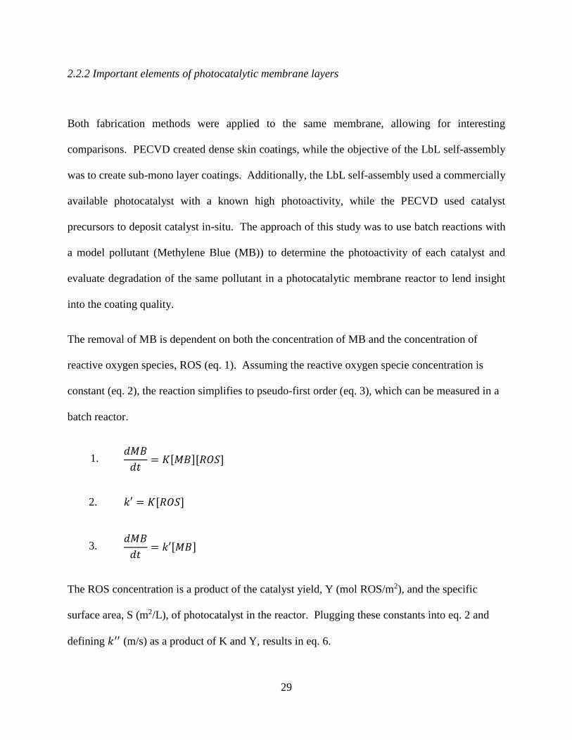
The removal of MB is dependent on both the concentration of MB and the concentration of
reactive oxygen species, ROS (eq. 1). Assuming the reactive oxygen specie concentration is
constant (eq. 2), the reaction simplifies to pseudo-first order (eq. 3), which can be measured in a
batch reactor.
1. 𝑑𝑀𝐵
𝑑𝑡= 𝐾[𝑀𝐵][𝑅𝑂𝑆]
2. 𝑘′ = 𝐾[𝑅𝑂𝑆]
3. 𝑑𝑀𝐵
𝑑𝑡= 𝑘′[𝑀𝐵]
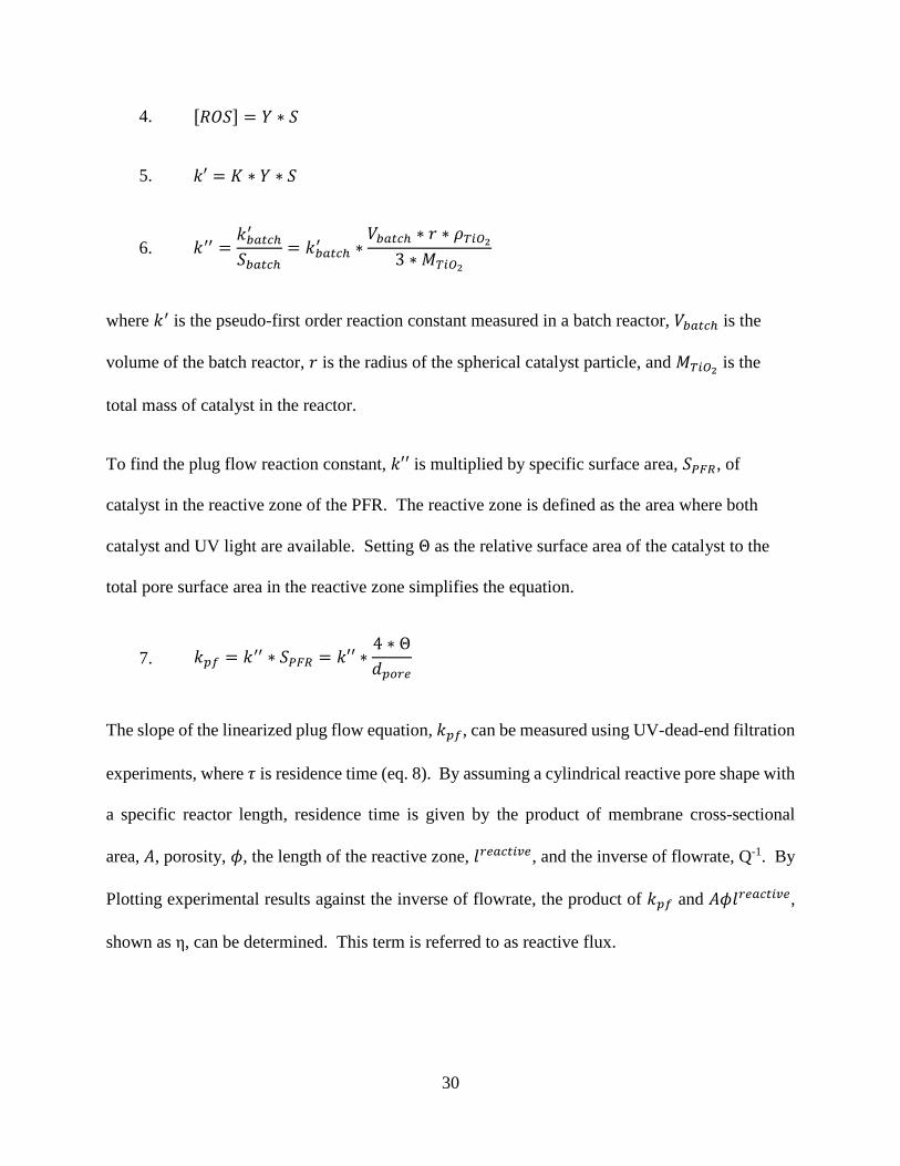
The ROS concentration is a product of the catalyst yield, Y (mol ROS/m2), and the specific
surface area, S (m2/L), of photocatalyst in the reactor. Plugging these constants into eq. 2 and
defining 𝑘′′ (m/s) as a product of K and Y, results in eq. 6.
30
4. [𝑅𝑂𝑆] = 𝑌 ∗ 𝑆
5. 𝑘′ = 𝐾 ∗ 𝑌 ∗ 𝑆
6. 𝑘′′ =𝑘𝑏𝑎𝑡𝑐ℎ
′
𝑆𝑏𝑎𝑡𝑐ℎ= 𝑘𝑏𝑎𝑡𝑐ℎ
′ ∗𝑉𝑏𝑎𝑡𝑐ℎ ∗ 𝑟 ∗ 𝜌𝑇𝑖𝑂2
3 ∗ 𝑀𝑇𝑖𝑂2
where 𝑘′ is the pseudo-first order reaction constant measured in a batch reactor, 𝑉𝑏𝑎𝑡𝑐ℎ is the
volume of the batch reactor, 𝑟 is the radius of the spherical catalyst particle, and 𝑀𝑇𝑖𝑂2 is the
total mass of catalyst in the reactor.
To find the plug flow reaction constant, 𝑘′′ is multiplied by specific surface area, 𝑆𝑃𝐹𝑅, of
catalyst in the reactive zone of the PFR. The reactive zone is defined as the area where both
catalyst and UV light are available. Setting Θ as the relative surface area of the catalyst to the
total pore surface area in the reactive zone simplifies the equation.
7. 𝑘𝑝𝑓 = 𝑘′′ ∗ 𝑆𝑃𝐹𝑅 = 𝑘′′ ∗4 ∗ Θ
𝑑𝑝𝑜𝑟𝑒
The slope of the linearized plug flow equation, 𝑘𝑝𝑓, can be measured using UV-dead-end filtration
experiments, where 𝜏 is residence time (eq. 8). By assuming a cylindrical reactive pore shape with
a specific reactor length, residence time is given by the product of membrane cross-sectional
area, 𝐴, porosity, 𝜙, the length of the reactive zone, 𝑙𝑟𝑒𝑎𝑐𝑡𝑖𝑣𝑒, and the inverse of flowrate, Q-1. By
Plotting experimental results against the inverse of flowrate, the product of 𝑘𝑝𝑓 and 𝐴𝜙𝑙𝑟𝑒𝑎𝑐𝑡𝑖𝑣𝑒,
shown as η, can be determined. This term is referred to as reactive flux.
31
8. ln (𝐶
𝐶0) = 𝑘𝑝𝑓𝜏 = 𝑘𝑝𝑓𝐴𝜙𝑙𝑟𝑒𝑎𝑐𝑡𝑖𝑣𝑒 ∗ (
1
𝑄)
9. 𝜂 = 𝑘𝑝𝑓𝐴𝜙𝑙𝑟𝑒𝑎𝑐𝑡𝑖𝑣𝑒
Using equations 7 and 9, a ratio can be taken between two coating techniques. With the use of
the same membrane, the cross-sectional area, porosity, and pore diameter are equal, leaving eq.
10. Here we can see the importance of both a long reactive zone and a dense coating to in
creating a highly efficient photocatalytic reactor. A ratio greater than 1 indicates the LbL
method has a higher quality coating and less than 1 indicates PECVD resulted in a better coating
with this membrane. Herein high quality refers to both higher amount of catalyst surface area
and optimal placement of the catalyst. The length of the reactive zone is a function of pore
morphology and depth of coating. By using the same membrane, the relative parameters, 𝑙 and
Θ, are attributed solely to the coating technique. The constants used in this approach are
summarized in Table 2.
10.
lLbL ∗ ΘLbL
lPECVD ∗ Θ𝑃𝐸𝐶𝑉𝐷=
(η)𝐿𝑏𝐿
𝑘𝐿𝑏𝐿′′ ∗
𝑘𝑃𝐸𝐶𝑉𝐷′′
(η)𝑃𝐸𝐶𝑉𝐷

32
Table 2: Summary of constants used in approach
Constant Units Description
K L·mol-1·s-1 Overall reaction constant for the degration of methylene blue by reactive
oxygen species
k' s-1 Product of [ROS] and K, pseudo-first order reaction constant
k'' L·s-1·m-2 k' normalized by the specific surface area of TiO2 in the reactor
η min·L-1 Reactive flux, slope of ln(C/Co) vs 1/Q, where C is concentration of meyhtlene
blue
Q L·min-1 Flowrate through membrane
l m Length of reactive area in pore
A m2 Cross-sectional area of membrane
Θ Dimensionless Ratio of catalyst surface area in pore to total pore wall area in reactive zone
lLbL*ΘLbL
lPECVD*ΘPECVD
Coating quality ratio, value larger than 1 indicates LbL results in a higher quality
coating. Value less than 1 indicates PECVD yields a higher quality coatingDimensionless

33
2.3 Experimental
2.3.1 Reagents
Polyelectrolytes used for the LbL deposition of catalyst included reagent grade
polydiallyldimethylammonium chloride (Aldrich, MW 100,000-200,000), polyacrylic acid
(Aldrich, MW 1,800), poly(sodium styrene sulfonate) (Aldrich, MW 70,000), and
poly(allylamine hydrochloride) (Aldrich, MW 70,000). Commercially available titanium dioxide
(Degussa P25) was used as a catalyst in all LbL self-assembly coatings. Titanium tetra-
isopropoxide (TTIP) (Sigma-Aldrich) was used as a precursor in plasma enhanced chemical
vapor deposition coatings. Methylene blue (Sigma) was used as a model pollutant in both batch
and photocatalytic filtration experiments. Potassium iodine (Jade Scientific), iodate (EM
Industries), and borate buffer (Sigma-Aldrich) solutions were used in chemical actinometry to
quantify UV fluence [13, 14]. All membranes were cleaned in nitric acid (EMD Performance
Materials) and sodium hydroxide (Sigma-Aldrich) solutions. Glass slides were cleaned with
detergent (Alconox), hydrochloric acid (EDM Performance Materials), and acetone (Sigma-
Aldrich). Piranha solution was prepared with a mixture of sulfuric acid (J.T. Baker) and
hydrogen peroxide (Fisher Scientific). Additionally, hydrochloric acid (EMD Performance
Materials) and sodium hydroxide (Sigma-Aldrich) were used for pH adjustments.
2.3.2 LbL assembly
LbL self-assembly involves a two-step coating process. First the polyelectrolytes are coated on a
substrate to modify the surface charge and then the polyelectrolyte-coated substrate is dipped in

34
suspended catalyst to adhere catalyst particles. Initial LbL deposition was performed on glass
slides (VWR, 24x60 mm). The slides were cleaned by consecutively sonicating in solutions of
detergent, hydrochloric acid, and acetone. After cleaning, the slides were oxidized with a 3:1
mixture of sulfuric acid and hydrogen peroxide. The clean slides were alternately dip coated in
anionic and cationic 0.02 M solutions of polyelectrolytes. After each layer of polyelectrolyte,
the samples were rinsed with DI water. The two polyelectrolyte systems used were PAH&PSS
and PDADMAC&PAA. With both systems, cationic polyelectrolytes were used as initiating
layers and anionic polyelectrolytes were used as the terminating layer. A complete coating of
polyelectrolytes consisted of 4 bilayers, with each bilayer having 1 anionic and 1 cationic
polyelectrolyte. After coating 4 bilayers of polyelectrolytes, the glass slides were dried in a
gentle stream of compressed air. The polyelectrolyte coated slides were then submerged in a 300
mg/L suspension of Degussa P25 photocatalyst for 30 minutes. To prepare the catalyst
suspension, the TiO2 was suspended in DI water and sonicated using a bath sonicator. Prior to
sonication, the pH of the catalyst suspension was adjusted to match the pH of the terminating
polyelectrolyte layer. Both 0.01 M and 0 M ionic strength catalyst suspensions were used for
investigation of double layer charge compression effects on deposited catalyst morphology.
Flat disc ceramic membranes (TAMI Industries, FR) with a 0.14 µm pore size were used for
fabrication of LbL self-assembled photocatalytic membranes. The membranes were cleaned
prior to coating by soaking for 30 minutes in 20 g/L sodium hydroxide at 80°C, followed by
soaking for 15 minutes in 5 ml/L nitric acid. The first LbL membrane was prepared with 4
bilayers of PDADMAC&PAA and 1 layer TiO2. The pH of the PAA solution and TiO2 were
adjusted to 5 and the TiO2 suspension had 0 M ionic strength. Additionally, a second membrane
was prepared with 5 total layers of TiO2 by repeating the alternating layers of

35
(PDADMAC&PAA)4 and TiO2 . During coating, only the support structure of the membrane
was exposed to polyelectrolytes and catalyst. Following deposition of catalyst, the membranes
were sintered at 500°C for 45 minutes (RHF 15/3, Carbolite Ltd).
2.3.3 Plasma enhanced chemical vapor deposition
Photocatalytic membranes fabricated with PECVD were prepared using the same flat disc
ceramic membranes used with the LbL technique. Membranes were coated at the European
Institute of Membranes, using a process previously developed and optimized [12]. Prior to the
deposition of catalyst, the membranes were cleaned by soaking for 30 minutes in 20 g/L sodium
hydroxide at 80°C, followed by soaking for 15 minutes in 5 ml/L nitric acid. The membrane was
then placed in the deposition chamber and a vacuum was applied. The membrane was heated to
150°C throughout deposition. Using argon as a carrier gas, titanium tetra-isopropoxide (TTIP)
was feed to the chamber along with oxygen. The flux ratio of TTIP to oxygen had been
previously optimized for maximum coating thickness and homogeneity. The carrier gas line was
heated to 100°C to prevent condensation of precursor. An R.F. induced plasma was applied for
20 minutes, resulting in the formation of titanium dioxide catalyst on the substrate. The
deposition process was repeated to create 1 and 2 layer PECVD coated membranes. During
deposition, only the membrane support was exposed to PECVD.

36
2.3.4 Batch experiments
The photocatalytic efficiency of P25 and PECVD generated catalysts were measured in a UV
batch reactor. The batch reactor consisted of a UV exposure box, UV lamp (16 W, model
GPH330T5L/4, Atlantic Ultraviolet Corp), stir plate, and a beaker (Figure 3B). The UV lamp
emitted within the germicidal range, with 95% of emitted energy at the 254 nm wavelength.
Batch experiments with P25 and PECVD generated catalysts were conducted using MB as a
model pollutant. The catalyst suspension was prepared by suspending catalyst particles in DI
water and adjusting the pH using HCl. The Degussa P25 suspension had pH 4 and the PECVD
generated catalyst had pH 3.1. MB was added to the catalyst suspensions and allowed to
equilibrate for 30 minutes prior to UV exposure. During the batch test, the fluid remained stirred
and samples were taken at periodic intervals of UV exposure.
To prepare PECVD generated catalyst powder, thin layers of catalyst were deposited on silicon
wafers and sintered at 500°C for 1 hour. Using a micro-spatula, the coatings were then scraped
to generate loose powder. This powder was suspended with DI water and sonicated for 2 hours.
The particle diameters of the suspended catalyst were measured prior to MB experiments
(Brookhaven, ZetaPALS).
2.3.5 Dead-end filtration experiments
A UV dead-end filtration test apparatus was constructed by machining a permeate window in a
47 mm diameter stainless steel dead-end filtration cell (Sterlitech). A 1/8” thick quartz glass disc
(Technical Glass Products) was fit into the window with a glass hose barb to capture the
37
permeate stream. During UV dead-end filtration experiments, the membrane holder was
positioned such that the permeate window was uniformly exposed to UV light. The dead-end
filtration experiments utilized the same UV exposure box and UV lamp as the batch reaction
experiments. All dead-end filtration experiments were conducted in the constant pressure
regime. The first stage of filtration was performed in the absence of UV until constant a
permeate concentration of MB was achieved. After reaching a steady permeate concentration,
the permeate was exposed to UV through the quartz window and permeate samples were
collected at regular intervals. Flux was recorded using a data acquisition system.
38
Figure 3: UV-microfiltration test apparatus. A: 1) Compressed air cylinder 2) Stainless steel
feed tank 3) UV exposure box 4) Germicidal UV lamp 5) Membrane filtration cell with permeate
UV window 6) Collection beaker with data acquisition system B: 1) UV exposure box 2)
Germicidal UV lamp 3) Beaker and stir plate.
1
2
3
6
4A
B
5
1
3
2

39
2.3.6 Measuring concentration of Methylene Blue
Methylene Blue sample absorbance was measured at 663 nm and converted to concentration
using the Beer-Lambert Law, eq. 11.
11. 𝑎𝑏𝑠 = 𝜖 ∗ 𝐶𝑚𝑏 ∗ 𝑙
Where 𝜖 is the extinction coefficient, 𝐶𝑚𝑏is the MB molar concentration, and 𝑙 is the optical path
length. An extinction coefficient of 69,362 𝐿
𝑚𝑜𝑙 𝑐𝑚 at 663 nm was determined by measuring the
absorbance (MultiSpec, 1501, Shimadzu) from a series of MB dilutions. The optical path length
was 1 cm.
2.3.7 UV fluence quantification
The UV fluence was measured using chemical actinometry. A stock solution of 0.1 M iodate
and 0.01 M sodium borate was prepared and the pH was adjusted to 9.25. For each sample, 100
mL of stock solution was added to a beaker with 0.6 M potassium iodide. The quantum yield
was calculated according to eq. 12, where T is temperature in Celsius and C is the molar
concentration [13]. The sample was placed in the UV exposure box and exposed to UV light
while under continuous stirring for a given period of time. The absorbance at 352 nm of an
irradiated and non-irradiated baseline sample were measured. The fluence was calculated
according to eq. 13 [15].

40
12. Φ (mol
einstein) = 0.75[1 + 0.02(𝑇 − 20.7)][1 + 0.23(𝐶 − 0.577)],
13. 𝐹 (𝐽
𝑐𝑚2) =𝜂∗Δ𝐴352∗𝑉
ϵ∗S∗Φ,
where η is a conversion factor, 4.72x10⁵ J/Einstein, Δ𝐴352is the difference in absorbance from
the baseline to the irradiated sample at 352 nm, V is the volume of the sample, ϵ is the molar
absorption coefficient at 352 nm, 26,400 L/mol, S is the exposed surface area, cm2, and Φ is the
quantum yield as calculated in eq. 12.
2.3.8 Scanning electron microscope imaging
Scanning electron microscopy (SEM) images of the LbL coated glass slides and membranes
were recorded (JEOL 6610LV SEM) under various magnifications. Samples of membrane and
glass slides for SEM imaging were obtained by breaking the sample, mounting a piece onto an
aluminum stub, and coating the mounted sample with ~ 20 nm thick layer of gold (Emscope
Sputter Coater, model SC 500, Quorum Technologies). The sample was then scanned to ensure
uniform appearance and images were taken of representative areas.
2.4 Results and Discussion
The experimental parameters are summarized in Table 3. Preliminary results indicated the single
layer LbL membrane had limited photoactivity and UV dead-end filtration experiments were not
continued with this membrane. Photocatalytic results with methylene blue are reported for the 1

41
and 2 layer PECVD membranes and the 5 layer LbL membrane. SEM images were taken of 1
LbL coatings on glass slides and membrane pieces.
Table 3: LbL and PECVD experimental parameters
2.4.1 Titanium dioxide LbL assembly characterization
The polyelectrolyte systems employed in LbL self-assembly were PAH+PSS and
PDADMAC+PAA. A primary difference between the two systems is the degree of dissociation
of the terminating polyelectrolyte. PSS is a strong polyelectrolyte and fully dissociated in
solution. In contrast, PAA is weak polyelectrolyte and the level of dissociation is dependent on
solution pH. Additionally, the initiating polyelectrolytes layers differ. PAH is classified as a
weak polyelectrolyte and PDADMAC is a strong polyelectrolyte. Figure 4A shows an image of
the (PAH+PSS)4+TiO2 coating on a glass slide. The coating technique resulted in a sub-
monolayer deposition of TiO2. With the aid of an image processing software (ImageJ), the
deposited particle radius was estimated to be approximately 20 nm. This is slightly larger than
reported values for Degussa P25, indicating either measurement error or possibly aggregates
consisting of several particles [16]. This morphology is in contrast to previously reported thin
Coating Technique Catalyst
Layers of
Catalyst Experiments Model Pollutant Imaging
1 -- --Glass Slides
Membrane
5Batch
Dead-endMethylene Blue --
1 --
2 --
Methylene Blue
Layer-by-layer Self-Assembly
Plasma Ehanced Chemical Vapor
Deposition
Degussa P25
PECVD
Generated
Catalyst
Batch
Dead-end
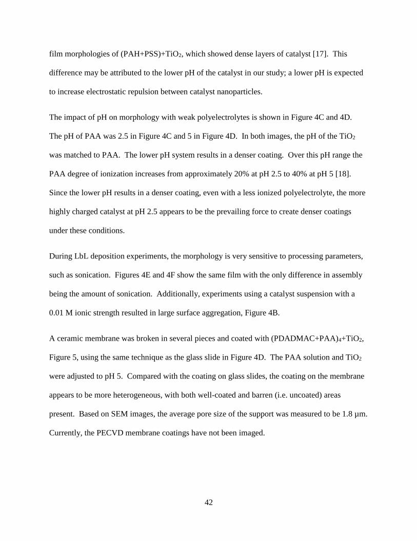
42
film morphologies of (PAH+PSS)+TiO2, which showed dense layers of catalyst [17]. This
difference may be attributed to the lower pH of the catalyst in our study; a lower pH is expected
to increase electrostatic repulsion between catalyst nanoparticles.
The impact of pH on morphology with weak polyelectrolytes is shown in Figure 4C and 4D.
The pH of PAA was 2.5 in Figure 4C and 5 in Figure 4D. In both images, the pH of the TiO2
was matched to PAA. The lower pH system results in a denser coating. Over this pH range the
PAA degree of ionization increases from approximately 20% at pH 2.5 to 40% at pH 5 [18].
Since the lower pH results in a denser coating, even with a less ionized polyelectrolyte, the more
highly charged catalyst at pH 2.5 appears to be the prevailing force to create denser coatings
under these conditions.
During LbL deposition experiments, the morphology is very sensitive to processing parameters,
such as sonication. Figures 4E and 4F show the same film with the only difference in assembly
being the amount of sonication. Additionally, experiments using a catalyst suspension with a
0.01 M ionic strength resulted in large surface aggregation, Figure 4B.
A ceramic membrane was broken in several pieces and coated with (PDADMAC+PAA)4+TiO2,
Figure 5, using the same technique as the glass slide in Figure 4D. The PAA solution and TiO2
were adjusted to pH 5. Compared with the coating on glass slides, the coating on the membrane
appears to be more heterogeneous, with both well-coated and barren (i.e. uncoated) areas
present. Based on SEM images, the average pore size of the support was measured to be 1.8 µm.
Currently, the PECVD membrane coatings have not been imaged.

43
Figure 4: SEM images of LbL assembly of TiO2 nanoparticles on glass slides:
A) (PAH+PSS)+TiO2;
B) (PDADMAC+PAA)4+TiO2 with catalyst in 0.01 M ionic strength solution;
C) (PDADMAC+PAA)4+TiO2 with PAA and TiO2 pH 2.5;
D) (PDADMAC+PAA)4+TiO2 with PAA and TiO2 pH 5;
E) (PDADMAC+PAA)4+TiO2 using high power probe sonicator;
F) (PDADMAC+PAA)4+TiO2 using bath sonicator.

44
Figure 5: SEM images of (PDADMAC+PAA)4+TiO2 coated ceramic membranes
2.4.2 Batch experiments on photocatalytic oxidation of methylene blue
Batch experiments with MB were performed with Degussa P25, the catalyst used to fabricate the
LbL membrane, and PECVD generated catalyst (Figure 6). The initial concentration of MB was
approximately 2 mg/L in all experiments. There was limited MB degradation in batch
experiments performed without catalyst (-□-, Figure 6). A catalyst loading of 10 mg/L was used
in experiments with P25 and 17 mg/L was used for experiments with PECVD. These loadings
were chosen to result in a measurable degradation of MB, while not creating an opaque solution
that would shield UV. Prior to the addition of MB, the particle size for each catalyst was
A
D
B
C

45
measured. The suspended P25 catalyst was 268 ± 14 nm. This is approximately 10 times larger
than reported values for individual P25 particles and it is likely that the suspension consisted of
aggregated particles. The suspended PECVD catalyst was 6.7 ± 3.3 µm, significantly larger than
P25. Both catalystic reactions followed a linear natural log dependence on time, indicating
pseudo-first order reaction kinetics. From Figure 6, it appears that P25 is more
photocatalytically active than PECVD catalyst, but after normalizing the first order reaction
constant by specific surface in the reactor, assuming spherical particles, the two catalysts have a
similar photoactivity. The normalized first order reaction constants are 0.008 ± 0.0015 𝐿
𝑚2𝑠 and
0.006 𝐿
𝑚2𝑠 for P25 and PECVD generated catalysts, respectively. Batch testing for PECVD
generated catalyst was only completed once, due to a limited quantity of powdered catalyst
available.
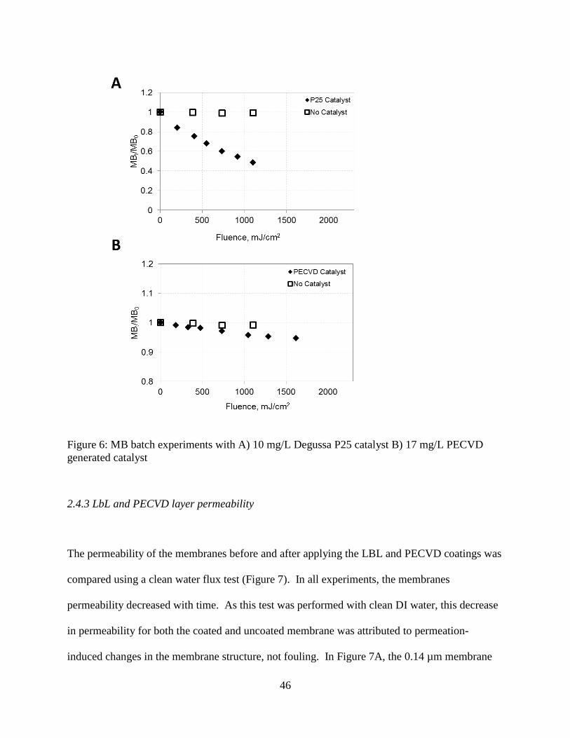
46
Figure 6: MB batch experiments with A) 10 mg/L Degussa P25 catalyst B) 17 mg/L PECVD
generated catalyst
2.4.3 LbL and PECVD layer permeability
The permeability of the membranes before and after applying the LBL and PECVD coatings was
compared using a clean water flux test (Figure 7). In all experiments, the membranes
permeability decreased with time. As this test was performed with clean DI water, this decrease
in permeability for both the coated and uncoated membrane was attributed to permeation-
induced changes in the membrane structure, not fouling. In Figure 7A, the 0.14 µm membrane
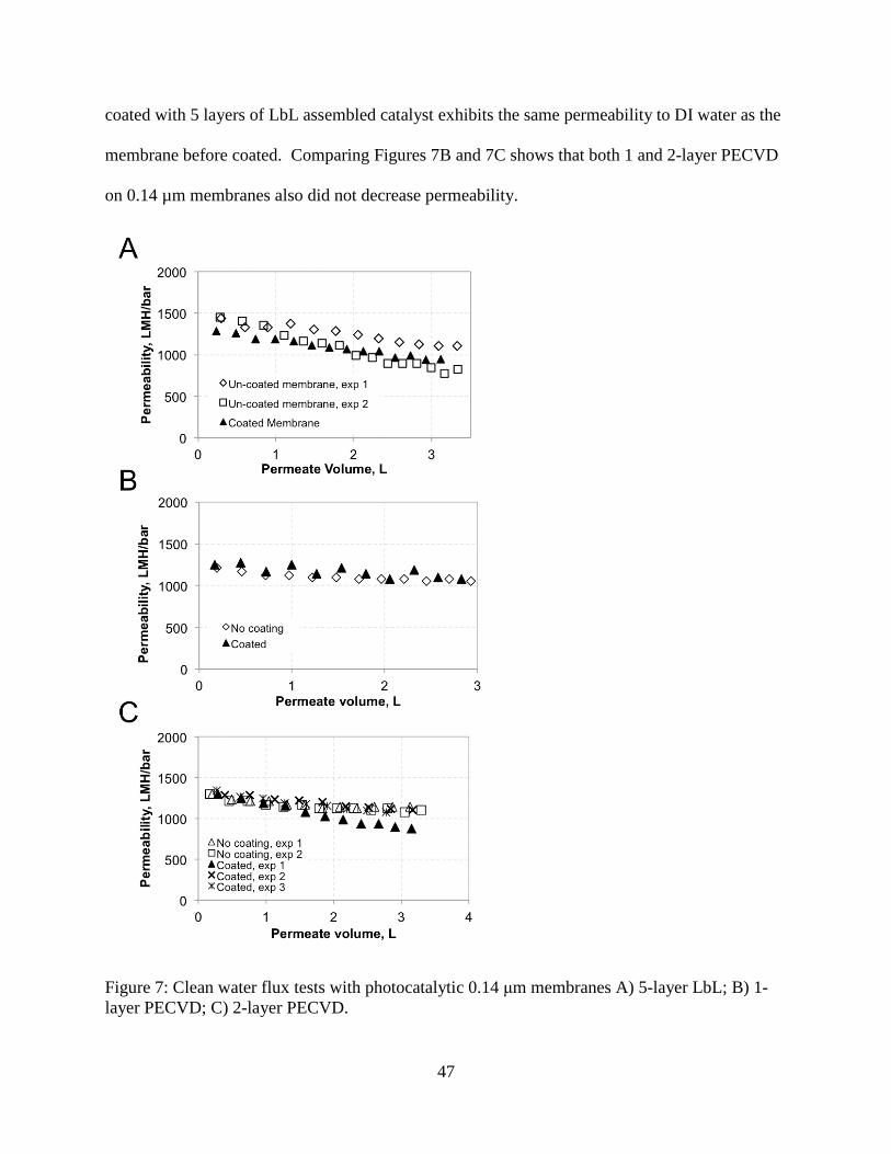
47
coated with 5 layers of LbL assembled catalyst exhibits the same permeability to DI water as the
membrane before coated. Comparing Figures 7B and 7C shows that both 1 and 2-layer PECVD
on 0.14 µm membranes also did not decrease permeability.
Figure 7: Clean water flux tests with photocatalytic 0.14 μm membranes A) 5-layer LbL; B) 1-
layer PECVD; C) 2-layer PECVD.

48
2.4.4 UV MB dead-end filtration and analysis
Comparison of the photocatalytic efficiency of the PECVD and LbL fabricated membranes was
performed using UV dead-end filtration experiments with MB (Figure 8). Each experiment was
repeated 3 times under the same conditions and all data are plotted with the linearized plug flow
reactor equation (eq. 8). Results are shown for membranes coated with 1 and 2-layers of PECVD
and 5-layers of LbL. Experiments show a strong linear dependence when MB degradation is
plotted against the inverse of flow rate, which is proportional to residence time. A 95%
confidence interval was generated for the linear regression model in comparison to the
experimental values (Table 4). From the results, the photocatalytic degradation of MB in the
first two experiments with the 5-layer LbL membrane are equivalent, while the third experiment
appears significantly lower. This could be indication of poor catalyst adhesion. Comparison of
the first and third experiment with the 1-layer PECVD membrane indicates there was not a
change in photocatalytic activity during this set of experiments. Similar to the 5-layer LbL, the
third experiment of the 2-layer PECVD membrane has a slope significantly less than the first
two. Comparing the photocatalytic efficiency of coating technique, with α = 0.1, shows that the
LbL membrane has a significantly different photocatalytic activity than the 1-layer PECVD
membrane. There is not a difference between the 1 and 2-layer PECVD and 2 -layer PECVD
and LbL self-assembly.

49
Figure 8: MB UV dead-end filtration experiments A) 0.14 µm, 1 layer PECVD B) 0.14 µm 2
layers PECVD C) 0.14 µm, 5-layer LbL
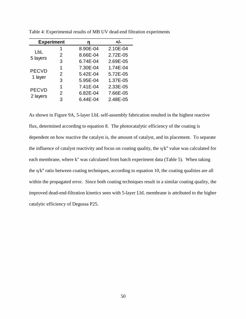
50
Table 4: Experimental results of MB UV dead-end filtration experiments
As shown in Figure 9A, 5-layer LbL self-assembly fabrication resulted in the highest reactive
flux, determined according to equation 8. The photocatalytic efficiency of the coating is
dependent on how reactive the catalyst is, the amount of catalyst, and its placement. To separate
the influence of catalyst reactivity and focus on coating quality, the η/k'' value was calculated for
each membrane, where k'' was calculated from batch experiment data (Table 5). When taking
the η/k'' ratio between coating techniques, according to equation 10, the coating qualities are all
within the propagated error. Since both coating techniques result in a similar coating quality, the
improved dead-end-filtration kinetics seen with 5-layer LbL membrane is attributed to the higher
catalytic efficiency of Degussa P25.
η +/-
1 8.90E-04 2.10E-04
2 8.66E-04 2.72E-05
3 6.74E-04 2.69E-05
1 7.30E-04 1.74E-04
2 5.42E-04 5.72E-05
3 5.95E-04 1.37E-05
1 7.41E-04 2.33E-05
2 6.82E-04 7.66E-05
3 6.44E-04 2.48E-05
Experiment
PECVD
1 layer
PECVD
2 layers
LbL
5 layers

51
Table 5: LbL self-assembly and PECVD coating quality
Coating Technique
PECVD:
2 layer6.89E-04 2.81E-05 6.0E-03 3.72E-06 1.15E-01 4.68E-03 1.00E+00 5.77E-02
PECVD:
1 layer6.22E-04 5.59E-05 6.0E-03 3.72E-06 1.04E-01 9.32E-03 9.03E-01 8.92E-02
LbL:
5 layers8.10E-04 6.83E-05 7.9E-03 7.5E-04 1.03E-01 1.30E-02 8.93E-01 1.19E-01
η, +/- k'', +/- η/k'', +/- Θxlx/Θyly, +/-
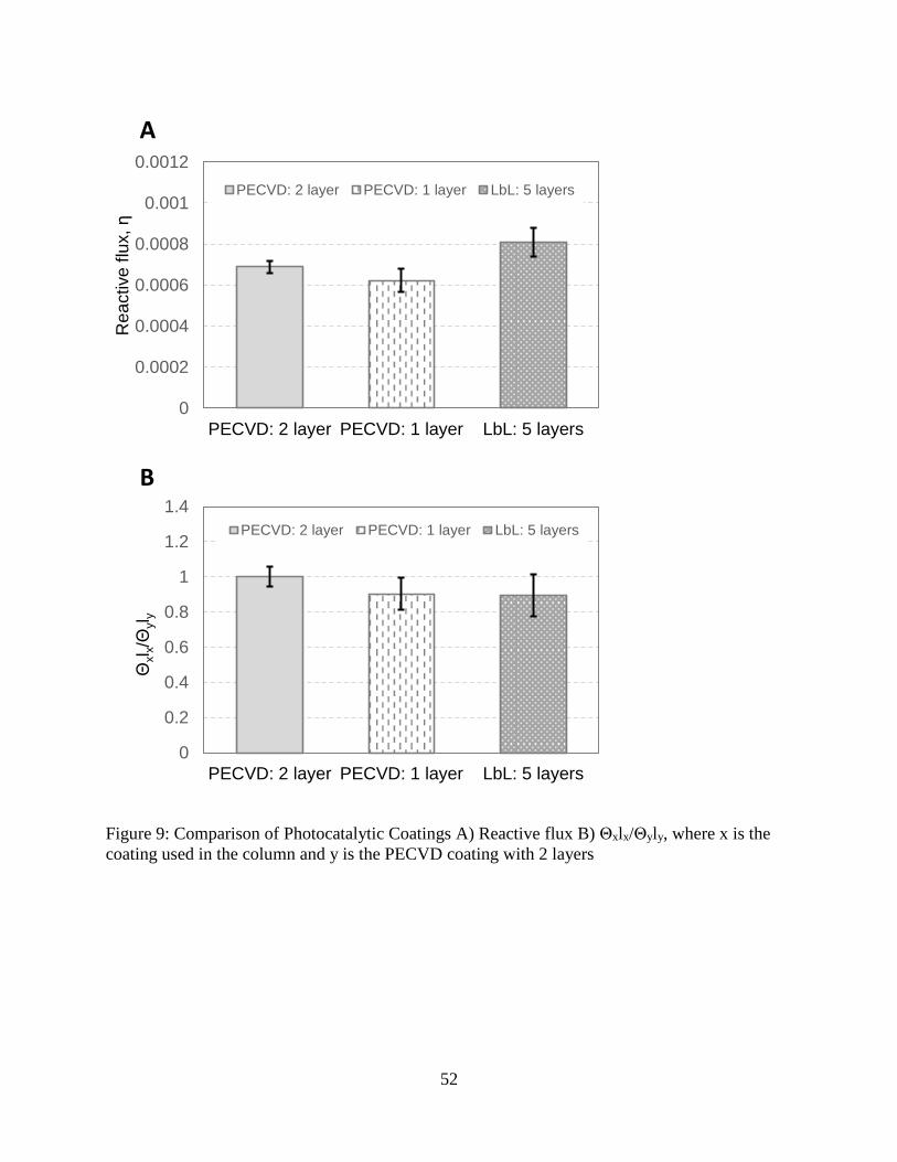
52
Figure 9: Comparison of Photocatalytic Coatings A) Reactive flux B) Θxlx/Θyly, where x is the
coating used in the column and y is the PECVD coating with 2 layers
0
0.0002
0.0004
0.0006
0.0008
0.001
0.0012
PECVD: 2 layer PECVD: 1 layer LbL: 5 layers
Rea
ctive
flu
x, η
PECVD: 2 layer PECVD: 1 layer LbL: 5 layers
0
0.2
0.4
0.6
0.8
1
1.2
1.4
PECVD: 2 layer PECVD: 1 layer LbL: 5 layers
Θxl x/Θ
yl y
PECVD: 2 layer PECVD: 1 layer LbL: 5 layers
A
B
53
2.5 Conclusion
A sub-mono layer fabrication technique using LbL self-assembly has been developed for
deposition of titanium dioxide photocatalyst on ceramic membrane support structures. The
resulting photocatalytic layers do not reduce the membrane permeability. In comparison with
established PECVD processes, the membrane had a higher overall rate of pollutant removal
during UV dead-end filtration experiments. Insight into the relative coating quality was
determined by normalizing the dead-end filtration results with catalyst efficiency. This indicated
that both coating techniques result in a similar coating-quality and therefore the higher rate of
removal seen with LbL self-assembly is attributed to the improved catalyst efficiency of P25.
This analysis points to pathways for improving each coating technique. LbL, with its high
catalyst efficiency, should target increasing the amount of catalyst in the reactive zone. In
contrast, PECVD, with a lower catalyst reactivity, should focus on increasing catalytic
efficiency. While this study analyzed two coating techniques using the same substrate, a similar
comparison can be made to find the optimal substrate geometry by coating different substrates
with the same coating technique.

54
REFERENCES
55
REFERENCES
1. Brezova, V.; Jankovicova, M.; Soldan, M.; Blazkova, A.; Rehakova, M.; Surina, I.;
Ceppan, M.; Havlinova, B., Photocatalytic Degradation of p-Toluenesulphonic Acid in
Aqueous Systems Containing Powdered and Immobilized Titanium-Dioxide. Journal of
Photochemistry and Photobiology a-Chemistry 1994, 83 (1), 69-75.
2. Zhang, H. M.; Quan, X.; Chen, S.; Zhao, H. M.; Zhao, Y. Z., Fabrication of
photocatalytic membrane and evaluation its efficiency in removal of organic pollutants
from water. Separation and Purification Technology 2006, 50 (2), 147-155.
3. Chong, M. N.; Jin, B.; Chow, C. W. K.; Saint, C., Recent developments in photocatalytic
water treatment technology: A review. Water Research 2010, 44 (10), 2997-3027.
4. Mozia, S., Photocatalytic membrane reactors (PMRs) in water and wastewater treatment.
A review. Separation and Purification Technology 2010, 73 (2), 71-91.
5. Bosc, F.; Ayral, A.; Guizard, C., Mesoporous anatase coatings for coupling membrane
separation and photocatalyzed reactions. Journal of Membrane Science 2005, 265 (1-2),
13-19.
6. Bosc, F.; Ayral, A.; Guizard, C., Mesoporous anatase coatings for coupling membrane
separation and photocatalyzed reactions. Journal of Membrane Science 2005, 265 (1-2),
13-19.
7. Athanasekou, C. P.; Romanos, G. E.; Katsaros, F. K.; Kordatos, K.; Likodimos, V.;
Falaras, P., Very efficient composite titania membranes in hybrid
ultrafiltration/photocatalysis water treatment processes. Journal of Membrane Science
2012, 392, 192-203.
8. Wang, W. Y.; Irawan, A.; Ku, Y., Photocatalytic degradation of Acid Red 4 using a
titanium dioxide membrane supported on a porous ceramic tube. Water Research 2008,
42 (19), 4725-4732.
9. Kim, Tae-Hyun, and Byeong-Hyeok Sohn. "Photocatalytic Thin Films Containing TiO2
Nanoparticles by the Layer-by-layer Self-assembling Method." Applied Surface Science
201.1-4 (2002): 109-14.
10. Sobczyk-Guzenda, A.; Pietrzyk, B.; Szymanowski, H.; Gazicki-Lipman, M.; Jakubowski,
W., Photocatalytic activity of thin TiO2 films deposited using sol-gel and plasma
enhanced chemical vapor deposition methods. Ceramics International 2013, 39 (3), 2787-
2794.
11. Ding, Z.; Hu, X. J.; Yue, P. L.; Lu, G. Q.; Greenfield, P. F., Synthesis of anatase TiO2
supported on porous solids by chemical vapor deposition. Catalysis Today 2001, 68 (1-
3), 173-182.

56
12. Julbe, Anne, Vincent Rouessac, Jean Durand, and André Ayral., New Approaches in the
Design of Ceramic and Hybrid Membranes. Journal of Membrane Science 316.1-2
(2008): 176-85.
13. Rahn, R. O., Potassium iodide as a chemical actinometer for 254 nm radiation: Use of
iodate as an electron scavenger (vol. 66, pg. 450, 1997). Photochemistry and
Photobiology 1997, 66 (6), 885-885.
14. Guo, B.; Pasco, E. V.; Xagoraraki, I.; Tarabara, V. V. Virus removal and inactivation in a
hybrid microfiltration-UV process with a photocatalytic membrane. Separ. Purif.
Technol.2015, 149, 245–254.
15. Rahn, R. O.; Xu, P.; Miller, S. L., Dosimetry of room-air germicidal (254 nm) radiation
using spherical actinometry. Photochemistry and Photobiology 1999, 70 (3), 314-318.
16. Porter, J. F.; Li, Y. G.; Chan, C. K., The effect of calcination on the microstructural
characteristics and photoreactivity of Degussa P-25 TiO2. Journal of Materials
Science1999, 34 (7), 1523-1531.
17. Priya, D. N.; Modak, J. M.; Raichur, A. M., LbL Fabricated Poly(Styrene
Sulfonate)/TiO2 Multilayer Thin Films for Environmental Applications. Acs Applied
Materials & Interfaces 2009, 1 (11), 2684-2693.
18. Zhang, H. M.; Quan, X.; Chen, S.; Zhao, H. M.; Zhao, Y. Z., Fabrication of
photocatalytic membrane and evaluation its efficiency in removal of organic pollutants
from water. Separation and Purification Technology 2006, 50 (2), 147-155.

57
CHAPTER 3
Photocatalytic membranes for virus inactivation
3.1 Introduction
Photocatalysis has been proposed as a means of disinfection since 1985, when Matsunga et al
successfully inactivated Lactobacillus acidophilus, Saccharomyces cerevisiae, and Eschericia
coli in suspended TiO2/Pt catalyst [1]. This work has since been extended to other
microorganisms, including the photocatalytic inactivation of bacteriophages [2] and human
viruses [3]. As shown by Cho, viruses pose a more significant challenge for photocatalytic
inactivation than bacteria, which the authors attributed to the lack of enzymes and other sensitive
systems in viruses [4].
While a majority of photocatalytic disinfection research has focused on using suspended catalytic
reactors, thin film technologies have been proposed as a practical means of implementing
photocatalytic disinfection [5]. This application eliminates concerns of catalyst aggregation and
the need for catalyst recovery systems. Using a membrane as a thin film contactor, the resulting
photocatalytic membrane, depending on the catalyst location, has several benefits to the
photocatalytic and separative functions; the benefits include reduced fouling, reduced turbidity
during photocatalysis, and concentration of pollutants near catalyst surfaces.
As described in Chapter 2, a novel photocatalytic membrane was prepared using LbL self-
assembly to apply TiO2 catalyst to the support structure of a ceramic disc membrane. This study
investigates the use of this photocatalytic membrane for inactivation of MS2 and P22
bacteriophages. The inactivation of the bacteriophages using a photocatalyst is a multi-step

58
process that includes diffusion of the phage through the boundary layer, absorption to the
catalyst, inactivation of the phage, and desorption away from the catalyst. In this context, testing
the photocatalytic inactivation of MS2, a 20 nm spherical RNA phage and P22, a 60 nm DNA
phage with a tail, provides an interesting comparison and can lend insight into the selection and
design of photocatalytic processes.
3.2 Experimental
3.2.1 Reagents
The membrane modified by a 5-layer LbL self-assembled coating (see Chapter 2) was used in all
photocatalytic filtration experiments. Degussa P25 TiO2 nanoparticles were used for batch
experiments. MS2 was acquired from ATCC (15597-B1) and P22 was acquired from Professor
Charles P. Gerba at the University of Arizona.
3.2.2 Batch Experiments
The batch reactor consisted of a UV exposure box, UV lamp (16 W, model GPH330T5L/4,
Atlantic Ultraviolet Corp), stir plate, and a beaker (Figure 1b). The UV lamp is within the
germicidal range, with 95% of emitted energy at 254 nm. Details on fluence quantification are
provided in chapter 2. Batch experiments with P25 were conducted with MS2 and P22
bacteriophages. A 1,000 mg/L catalyst suspension was prepared by suspending P25 in DI water
59
and adjusting the pH to 5 using HCl. This suspension was sonicated for 30 minutes using a
probe sonicator. A prescribed amount of the suspended catalyst was then added to the
bacteriophage spiked solutions, resulting in a 1.25 mg/L suspension of catalyst. After the
catalyst was added, the solution was stirred and allowed to equilibrate for 10 minutes prior to UV
exposure. During the batch test, the fluid remained stirred and samples were taken at periodic
intervals.
3.2.3 Dead-end filtration experiments
A UV dead-end filtration test apparatus was constructed by machining a permeate window in a
47 mm diameter stainless steel dead-end filtration cell (Sterlitech). A 1/8” thick quartz glass disc
(Technical Glass Products) was fit into the window with a glass hose barb to capture the
permeate stream. During UV dead-end filtration experiments, the membrane holder was
positioned such that the permeate window was uniformly exposed to UV light. The dead-end
filtration experiments utilized the same UV exposure box and UV lamp as the batch reaction
experiments. All dead-end filtration experiments were conducted with a constant pressure
configuration and permeate samples were collected for 20 minutes prior to UV exposure to
account for adsorption of bacteriophages to the membrane, filtration cell, and tubing. Permeate
samples where then taken periodically after exposure to UV. Permeate flow rate was recorded
with a data acquisition system.
60
3.2.4 Quantification of bacteriophage concentration
Bacteriophage culturing and quantification was performed by The Water Quality,
Environmental, and Molecular Microbiology Laboratory at Michigan State University. Samples
were diluted in phosphate buffered water and replicate volumes of the dilution series were
analyzed by double agar overlay, using a host bacterium in the logarithmic growth phase to
produce plates with countable plaques after 16-24 hour incubation at 37°C. The host bacterium
for MS2 was E.coli Famp (ATCC # 700891). E.coli Famp was grown and maintained in Tryptic
Soy Broth (Becton Dickson) with ampicillin and streptomycin to maintain the F+ plasmid. The
host bacterium for P22 was Salmonella LT2 (pLM2) 1217 (HER #1023). Each replicate plate is
an assay of 2ml of the sample, either undiluted or diluted. MS2 and P22 were cultured overnight
and then filtered through a 0.22 µm membrane to remove bacterial cells. This filtrate was used
as the spiking suspension. The MS2 and P22 suspensions used for the photocatalytic batch and
dead-end filtration experiments were created by mixing the spiking suspension with laboratory
reagent water (Type 2) that had been sterilized by autoclaving. The pH of the suspension was
adjusted to below 5 with HCl. The target concentration of the viral suspensions was 108 plaque
forming units (PFU) per ml.

61
3.3 Results and Discussion
3.3.1 Bacteriophage batch experiments
Photocatalytic inactivation of MS2 and P22 in a batch reactor was performed with Degussa P25
catalyst, Figure 10. The initial MS2 concentration was 2.5x10⁸ PFU/mL and the initial P22
solution contained 4.0x10⁶ PFU/mL. A 5.5 log removal of MS2 was achieved after 734 mJ/cm2
fluence exposure. A 2.9 log removal of P22 was achieved after 73.5 mJ/cm2 UV fluence. Both
bacteriophages show a log-linear dependence on exposure time to UV, indicating pseudo-first
order kinetics, with MS2 having a reaction constant of 0.011 s-1 and P22 having a constant of
0.054 s-1. The reaction constant for MS2 is in line with reported values by Koizumi [2], who
demonstrated a reaction constant of 0.012 s-1, but using a higher catalyst loading and slightly
higher wattage lamp. Literature data on using Degussa P25 in a batch reactor to inactivate P22
could not be found for comparison.
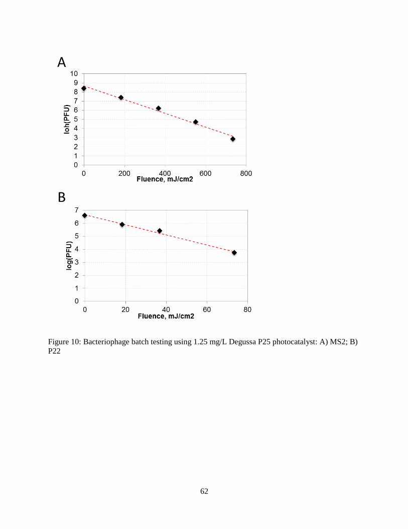
62
Figure 10: Bacteriophage batch testing using 1.25 mg/L Degussa P25 photocatalyst: A) MS2; B)
P22
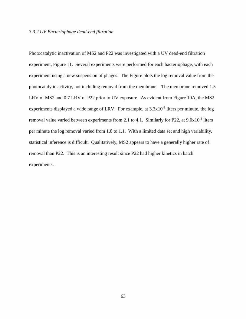
63
3.3.2 UV Bacteriophage dead-end filtration
Photocatalytic inactivation of MS2 and P22 was investigated with a UV dead-end filtration
experiment, Figure 11. Several experiments were performed for each bacteriophage, with each
experiment using a new suspension of phages. The Figure plots the log removal value from the
photocatalytic activity, not including removal from the membrane. The membrane removed 1.5
LRV of MS2 and 0.7 LRV of P22 prior to UV exposure. As evident from Figure 10A, the MS2
experiments displayed a wide range of LRV. For example, at 3.3x10⁻³ liters per minute, the log
removal value varied between experiments from 2.1 to 4.1. Similarly for P22, at 9.0x10⁻³ liters
per minute the log removal varied from 1.8 to 1.1. With a limited data set and high variability,
statistical inference is difficult. Qualitatively, MS2 appears to have a generally higher rate of
removal than P22. This is an interesting result since P22 had higher kinetics in batch
experiments.

64
Figure 11: UV dead-end filtration experiments A) MS2 B) P22

65
3.4 Conclusion
The inactivation of MS2 and P22 was tested using a batch reactor with suspended Degussa P25
photocatalyst and a UV dead-end filtration process using a photocatalytic membrane. During
batch testing both phages displayed first order kinetics. A 0.3 log removal of MS2 was achieved
with 73.5 mJ/cm2 fluence compared to 2.9 log removal of P22 at the same fluence dose. With
UV dead-end filtration, significant variation occurred between experiments and made a
quantitative conclusion difficult, though in contrast to batch experiments, during UV dead-end
filtration, MS2 appears to be more susceptible to inactivation than P22. This contrast may be
attributed to differences in the physical properties of P22 and MS2. P22, due to its larger size,
has a smaller diffusion coefficient, resulting in a lower concentration of available phages at the
catalyst surface. Additionally, the larger size of P22 may result in more damage to the phage as
it permeates the membrane. Differences in the surface properties may have affected the
adsorption-desorption rate of each phage on the catalyst surface, resulting in different
inactivation kinetics. Also bacteriophage aggregation, such as caused by a change in pH during
batch experiments, may have reduced the apparent viable phage count. Lastly, the contrasting
results may be attributed to experimental error, such as not reaching the dead-end test apparatus
absorption capacity for P22 prior to UV exposure. This study resulted in an interesting
comparison on the suitability of UV dead-end filtration and batch processes for bacteriophage
inactivation. Further investigation to determine the cause of the contrasting results will provide
useful knowledge in the selection and design of photocatalytic processes for virus inactivation.

66
REFERENCES

67
REFERENCES
1. Matsunaga, T.; Tomoda, R.; Nakajima, T.; Wake, H., Photoelectrochemical sterilization
of microbial-cells by semiconductor powders. Fems Microbiology Letters 1985, 29 (1-2),
211-214.
2. Koizumi, Y.; Taya, M., Kinetic evaluation of biocidal activity of titanium dioxide against
phage MS2 considering interaction between the phage and photocatalyst particles.
Biochemical Engineering Journal 2002, 12 (2), 107-116.
3. Nakano, R.; Ishiguro, H.; Yao, Y. Y.; Kajioka, J.; Fujishima, A.; Sunada, K.; Minoshima,
M.; Hashimoto, K.; Kubota, Y., Photocatalytic inactivation of influenza virus by titanium
dioxide thin film. Photochemical & Photobiological Sciences 2012, 11 (8), 1293-1298.
4. Cho, M.; Chung, H. M.; Choi, W. Y.; Yoon, J. Y., Different inactivation Behaviors of
MS-2 phage and Escherichia coli in TiO2 photocatalytic disinfection. Applied and
Environmental Microbiology 2005, 71 (1), 270-275.
5. Hajkova, P.; Spatenka, P.; Horsky, J.; Horska, I.; Kolouch, A., Photocatalytic Effect of
TiO(2) Films on Viruses and Bacteria. Plasma Processes and Polymers 2007, 4, S397-
S401.