PHD-4 Portable Helium Detector - Agilent | Chemical · PDF file ·...
8
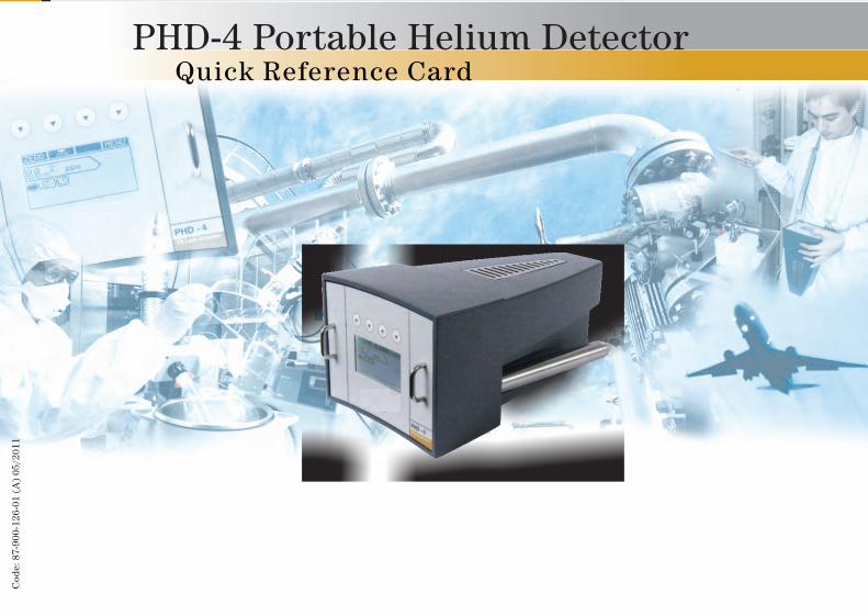
PHD-4 Portable Helium Detector Quick Reference Card Code: 87-900-126-01 (A) 05/2011
Transcript of PHD-4 Portable Helium Detector - Agilent | Chemical · PDF file ·...
Complete measurement screen page
ACTIVATION: Default at startupINFORMATION:
Leak ratedata
Bargraph
Status icons data
Function Function
Automatic zero activated
Fixed zero activated
High sensitivity activated
Low sensitivity activated
Set-point activated
Back-flow valveenabled
Icon Icon
Fixed /automatic zero
Backlight ON/OFF
Link to the Desktop menu
USER INTERFACE
Large Size Measurement screen Page
ENABLING: Menù SETUP/□ LARGE SCREEN ONACTIVATION: Automatic (5 sec delay)DEACTIVATION: Temporary (Button“OFF” or “MENU”)INFORMATION:
Leak ratedata
Battery status
Zero Status Measurement trend Unit of Measurement
Fixed /automatic zero
Backlight ON/OFF PHD-4 OFF
Link to the Desktop menu
Status icons
1 Sensor routine maintenance: sensor cleaning2 Battery routine maintenance: memory effect resetting3 To access your unit data
Use
r In
terf
ace
PHD-4 Portable Helium DetectorQuick Reference Card
Use
r in
terf
ace
The PHD-4 is complete with a rechargeable battery and related Power Supply. Always recharge the battery in a safe area.
Do not use the PHD-4 in environments containing potentially flammable gases or vapors. If the PHD-4 is used in combination with sampling safety devices (only if marked EEX ia IIAT4), the PHD-4 must be positioned outside the area with a risk of explosion.
Do not cover or obstruct the ventilation slots on the top part of the PHD-4 and the rear discharge duct.
!
!
!
Operative suggestions to get SHORT RECOVERY TIME and LONG PHD-4 LIFETIME:
PHD-4 SETTING: Begin Leak Checking with LOW SENS Always use SAFETY SET-POINT
CHECKING METHOD: Use low He concentr. in tracer gas (e.i. 5%He/N2) Use low tracer gas pressure (e.i. 0.5 Bar) Avoid overflow of He Avoid sniffing oil, dust or water
GENERAL: Periodically perform SAMPLING AUTOADJ. and
BATTERY CARE
••
••••
•
Operative suggestions to perform a GOOD LEAK CHECK:
Limit background of He Sweep slowly on suspected areas starting from
lower parts If He background is variable use AZ mode Operate in environments with stable room
temperature Periodically maintain filtering system Periodically check Reading precision
••
••
••
NOTE
NOTE Safe
ty in
fo
Op
erat
ive
info
Cod
e: 8
7-90
0-12
6-01
(A
) 05
/201
1
hoffmann
Stempel
hoffmann
Stempel
hoffmann
Stempel
hoffmann
Stempel
hoffmann
Stempel
hoffmann
Stempel
hoffmann
Stempel
hoffmann
Stempel

Sampling Pump: Removal and Replacement
Clean filter with grease remover and dry with compressed air
Sintered Filter: M anceainten
Disconnect air tubes Disconnect Pump electrical connector
Remove the pump Reverse procedure for new pump
Release disharged battery Unplug discharged battery connector
Connect new battery connector and fasten it
Internal Filter: Removal and Replacement
Remove saturated filter Position new filter and lock sampling line fitting
Rou
tin
e M
ain
ten
ance
Click and rotate. The enclosure will be released
Holding Filter cartridge turn fitting on the top by 1/4 of turn
Battery Pack: Removal and Replacement
Rou
tin
e M
ain
ten
ance
FRONT PANEL DISPLAY I/O - RS232 INTERFACE
VS Leak Detector
Use only Agilent-provided power supply with a ground connection. (90 - 240 Vac 50/60 Hz)
START UP
Press (and hold down ) the “D” key.Self test will start giving following results: v: Test OK. !: Test fail. R: Test must be repeated. PS: No battery or battery fail.
!
!
----
3 sec
Pin number Signal
1 Analog out (+)2 RS232 TX3 Rs232 RX4 Remote IN5 RS232 GND6 Analog out (-)
11 Relay 1 N.O.12 Relay 2 N.O.13 Relay 3 N.O.14 Relay 4 N.O.15 Relay common
Headset connector
Power connector
Enclosure fast unlock device
Exhaust Gas outlet
Analisys Probe
Multi-function keypad
Graphic display
Strap fixing point
Key “D” :ON
TECHNICAL DATA
Minimum detectable 2 PPM He concentration
-6Minimum detectable 5x10 mbar l/sHe leak rate
Operating conditions - temperature +5 °C to +35 °C- humidity 90 % RH (non cond.)
Battery operative range 4 h
Battery auto discharging 0.1% max. / day +20 °C
Battery life > 500 charge/discharge cycles (IEC standards)
Relay contacts data: 24 Vac/cc 1 A (resistive load)
0,3 A (inductive load)
Protection set-point levels Low sens. High sens.MINIMUM VALUE 200 PPM 2 PPMDEFAULT VALUE 400 PPM 100 PPMMAXIMUM VALUE 600 PPM 250 PPM
PIN 1-6 ANALOG VOLTAGE
Resolution 0,1 V
ppm
Tech
nic
al d
ata
base
un
itG
ener
al I
nfo
rmat
ion
- E
lect
rica
l con
nec
tion

Complete measurement screen page
ACTIVATION: Default at startupINFORMATION:
Leak ratedata
Bargraph
Status icons data
Function Function
Automatic zero activated
Fixed zero activated
High sensitivity activated
Low sensitivity activated
Set-point activated
Back-flow valveenabled
Icon Icon
Fixed /automatic zero
Backlight ON/OFF
Link to the Desktop menu
USER INTERFACE
Large Size Measurement screen Page
ENABLING: Menù SETUP/□ LARGE SCREEN ONACTIVATION: Automatic (5 sec delay)DEACTIVATION: Temporary (Button“OFF” or “MENU”)INFORMATION:
Leak ratedata
Battery status
Zero Status Measurement trend Unit of Measurement
Fixed /automatic zero
Backlight ON/OFF PHD-4 OFF
Link to the Desktop menu
Status icons
1 Sensor routine maintenance: sensor cleaning2 Battery routine maintenance: memory effect resetting3 To access your unit data
Use
r In
terf
ace
PHD-4 Portable Helium DetectorQuick Reference Card
Use
r in
terf
ace
The PHD-4 is complete with a rechargeable battery and related Power Supply. Always recharge the battery in a safe area.
Do not use the PHD-4 in environments containing potentially flammable gases or vapors. If the PHD-4 is used in combination with sampling safety devices (only if marked EEX ia IIAT4), the PHD-4 must be positioned outside the area with a risk of explosion.
Do not cover or obstruct the ventilation slots on the top part of the PHD-4 and the rear discharge duct.
!
!
!
Operative suggestions to get SHORT RECOVERY TIME and LONG PHD-4 LIFETIME:
PHD-4 SETTING: Begin Leak Checking with LOW SENS Always use SAFETY SET-POINT
CHECKING METHOD: Use low He concentr. in tracer gas (e.i. 5%He/N2) Use low tracer gas pressure (e.i. 0.5 Bar) Avoid overflow of He Avoid sniffing oil, dust or water
GENERAL: Periodically perform SAMPLING AUTOADJ. and
BATTERY CARE
••
••••
•
Operative suggestions to perform a GOOD LEAK CHECK:
Limit background of He Sweep slowly on suspected areas starting from
lower parts If He background is variable use AZ mode Operate in environments with stable room
temperature Periodically maintain filtering system Periodically check Reading precision
••
••
••
NOTE
NOTE Safe
ty in
fo
Op
erat
ive
info
Cod
e: 8
7-90
0-12
6-01
(A
) 05
/201
1
hoffmann
Stempel
hoffmann
Stempel
hoffmann
Stempel
hoffmann
Stempel
hoffmann
Stempel
hoffmann
Stempel
hoffmann
Stempel
hoffmann
Stempel