
Phase Shifting Transformer-LCL (PST-LCL) Filter: Modeling ...
11
HAL Id: hal-01745001 https://hal.archives-ouvertes.fr/hal-01745001 Submitted on 27 Mar 2018 HAL is a multi-disciplinary open access archive for the deposit and dissemination of sci- entific research documents, whether they are pub- lished or not. The documents may come from teaching and research institutions in France or abroad, or from public or private research centers. L’archive ouverte pluridisciplinaire HAL, est destinée au dépôt et à la diffusion de documents scientifiques de niveau recherche, publiés ou non, émanant des établissements d’enseignement et de recherche français ou étrangers, des laboratoires publics ou privés. Phase Shifting Transformer-LCL (PST-LCL) Filter: Modeling and Analysis Mohammad Amin Chitsazan, Andrzej Trzynadlowski To cite this version: Mohammad Amin Chitsazan, Andrzej Trzynadlowski. Phase Shifting Transformer-LCL (PST-LCL) Filter: Modeling and Analysis. American Journal of Electrical Power and Energy Systems, 2018, 7 (1), pp.1-10. 10.11648/j.epes.20180701.11. hal-01745001
Transcript of Phase Shifting Transformer-LCL (PST-LCL) Filter: Modeling ...

HAL Id: hal-01745001https://hal.archives-ouvertes.fr/hal-01745001
Submitted on 27 Mar 2018
HAL is a multi-disciplinary open accessarchive for the deposit and dissemination of sci-entific research documents, whether they are pub-lished or not. The documents may come fromteaching and research institutions in France orabroad, or from public or private research centers.
L’archive ouverte pluridisciplinaire HAL, estdestinée au dépôt et à la diffusion de documentsscientifiques de niveau recherche, publiés ou non,émanant des établissements d’enseignement et derecherche français ou étrangers, des laboratoirespublics ou privés.
Phase Shifting Transformer-LCL (PST-LCL) Filter:Modeling and Analysis
Mohammad Amin Chitsazan, Andrzej Trzynadlowski
To cite this version:Mohammad Amin Chitsazan, Andrzej Trzynadlowski. Phase Shifting Transformer-LCL (PST-LCL)Filter: Modeling and Analysis. American Journal of Electrical Power and Energy Systems, 2018, 7(1), pp.1-10. 10.11648/j.epes.20180701.11. hal-01745001

American Journal of Electrical Power and Energy Systems 2018; 7(1): 1-10
http://www.sciencepublishinggroup.com/j/epes
doi: 10.11648/j.epes.20180701.11
ISSN: 2326-912X (Print); ISSN: 2326-9200 (Online)
Phase Shifting Transformer-LCL (PST-LCL) Filter: Modeling and Analysis
Mohammad Amin Chitsazan*, Andrzej M Trzynadlowski
Department of Electrical and Biomedical Engineering, University of Nevada, Reno, USA
Email address:
*Corresponding author
To cite this article: Mohammad Amin Chitsazan, Andrzej M Trzynadlowski. Phase Shifting Transformer-LCL (PST-LCL) Filter: Modeling and Analysis.
American Journal of Electrical Power and Energy Systems. Vol. 7, No. 1, 2018, pp. 1-10. doi: 10.11648/j.epes.20180701.11
Received: February 14, 2018; Accepted: March 5, 2018; Published: March 27, 2018
Abstract: Power converters have been widely used in power systems to improve the quality and magnitude of the power
drawn from renewable energy sources. An LCL filter for connection of an inverter to the grid is often used to reduce the
harmonics generated by the inverter. Based on the different design methodologies, optimal parameters of LCL filters tend to
differ in wide ranges. This paper proposes a new approach to an LCL filter used for decreasing the harmonic currents. A phase
shifting transformer is added into the structure of an LCL filter to mitigate the harmonic current. The procedures and
techniques described in this paper are particularly suitable for the grid-connected photovoltaic energy systems.
Keywords: LCL Filters, Phase Shifting Transformers, PV Systems, Total Harmonic Distortion
1. Introduction
There is a growing demand for high-quality and reliable
electrical energy and protection systems have a significant
impact on improvement of the system reliability [1-2].
Energy systems based on photovoltaic (PV) cells have been
growing with a fast pace. Typically, they are connected to the
grid through multilevel voltage source inverters [3]-[5]. To
mitigate the harmonic content of the output current, a filter is
required between the inverter and the power grid. The
simplest solution is to use an inductor, but its huge size and
significant voltage drop are disadvantageous [6].
Therefore, an LCL passive filter is employed to mitigate
current harmonics caused by pulse width modulation (PWM)
at the point of common coupling (PCC). Compared by a first-
order L filter, the LCL filters meet the standards for grid
interconnection with smaller size and cost, particularly in
high-power cases [7]. Higher attenuation and cost savings
due to the weight and size reduction are additional
advantages. References [8] and [9] discuss application of
LCL filters in grid-connected inverters and PWM rectifiers,
where the amount of current distortion injected into the
utility grid is minimized. But, certain control difficulties may
arise. The LCL filter may cause instability of a closed-loop
control system, and trigger resonances between the inverter
and the grid.
Harmonic attenuation by the LCL filter results in lower
switching frequencies necessary for meeting harmonic
constraints, as defined by standards such as IEEE-519 [10],
and IEEE-1547 [11]. An appropriate mathematical model
must be developed to design the filter effectively. Suggested
solutions include parameter choice to suppress possible
resonances in the filter [12]-[13], active damping [14-16],
passive damping [17-8], and state feedback control with state
observer [18].
Passive damping method, a simple, effective, and reliable
solution, is implemented by inserting a resistor in series with
the capacitor in the filter. However, it causes extra power loss
and deteriorates the high-frequency harmonic attenuation
ability of the filter. Adding an RC circuit in parallel with the
capacitor of the filter is considered an effective means to
overcome this problem.
However, the high-frequency harmonic attenuation of the
passively damped LCL filter deteriorates when compared
with an undamped filter. Stability study of a system with the
LCL filter is described in [19] and current control techniques
in the LCL filter design are reviewed in [20].
This paper contains a comprehensive analysis and
modeling of a phase shifting transformer (PST). The

2 Mohammad Amin Chitsazan and Andrzej M Trzynadlowski: Phase Shifting Transformer-LCL
(PST-LCL) Filter: Modeling and Analysis
objective is to optimize its design for minimizing the total
harmonic distortion (THD) of the filtered current. The PST is
inserted in series with the capacitor. The phase angle of the
PST makes the filter controllable. Adjusting the phase angle
of the PST allows significant reduction of the THD. The PST
can also be used for harmonic mitigation, with no need for
adjustment of the LCL parameters, when the switching
frequency of the inverter changes.
The paper is organized as follows. Characteristics of the
PST are discussed in Section 2. The proposed filter is
presented in Section 3. Filter design procedure is briefly
explained in detail in Section 4. Simulation of two case
studies are described in Section 5, and Section 6 concludes
the considerations.
2. Phase shifting Transformer
PSTs allow an economical and reliable control of
electricity transfer over parallel conduits of electricity, e.g.,
an overhead transmission line and an underground cable [21-
25]. The power flow is controlled by changing the phase-shift
angle between the PST source- and load-side voltages [26].
PSTs are installed or are planned for installation in various
areas [27]. The PST can be modeled as a reactance in series
with a phase shift, as illustrated in Figure 1. The active power
passing through a line is a function of the phase angle .
However, in many cases the angles are controlled by humans.
Reference [28] presents a method to control the phase angle
by a voltage source converter (VSC). Furthermore, variations
of the phase angle are carried out by adding a regulated
quadrature voltage to the source’s line-to-neutral voltage
[29]. This paper shows that harmonic currents and the THD
can be adjusted by changing the phase angle of the PST.
Figure 1. Models of a transmission line without and with a PST.
3. Proposed FILTER
The proposed LCL filter is shown in Figure 2, where is
the inverter side inductor, is the grid-side inductor, is a
capacitor with a series damping resistor, R1 and R2 are
inductors’ resistances, and and are the inverter and grid
voltages. The inverter output current, the capacitor current,
and the grid current are denoted by , and ,respectively.
Figure 2. The proposed LCL filter (PST-LCL).
The per-phase model of the PST-LCL filter state-space model is
(1)
. . . (2)
. ! . . (3)
"####$ %&
&&&'
"###$(∠*( (∠* ∠*(∠* (∠*( ∠* 0 %&
&&' ,
"###$%&
&&' ! "###$ 0 0 0 0 %&&
&' , -. (4)
An important transfer function is / , where the
grid voltage is assumed to be an ideal voltage source capable
of damping all the harmonic frequencies. If one sets vG = 0,
which implies a current-controlled inverter, the transfer
functions of the LCL filter without and with the damping
resistor are, respectively
/0 ...1233.1 (5)

American Journal of Electrical Power and Energy Systems 2018; 7(1): 1-10 3
/0 .(.13...1
23.435.(.1533.1
(6)
Transfer functions of the PST-LCL without and with the
damping resistor are, respectively
/6780 =
...12∠*33.1
(7)
/6780 =.(.13
...12∠*3.435.(.1
533.1 (8)
Bode plots of the PST-LCL filter for different phase angles
are shown in Figure 3. The insertion of a phase shifting
transformer eliminates the gain spike, smoothing the overall
response and rolling-off between -75o and -325
o, instead of
the -180o at high frequencies.
Figure 3. Bode plots of PST-LCL for different phase shifts.
4. Filter design Procedure
When designing an LCL filter, several specifications, such
as the filter size, switching ripple attenuation [30], maximum
current ripple, or phase of the parallel capacitor branch on the
filter, must be considered. Passive or active damping is often
placed in series with the capacitor to prevent potential
resonances of the capacitor interacting with the grid, and
caused by reactive power requirements. The passive and
active damping have been described in [6] and [31],
respectively. Data needed for the filter design are listed in
Table 1.
Table 1. The parameters for designing the filter.
Line-to-line RMS voltage (inverter output)
9: Phase voltage (inverter output)
;< Rated active power
DC-link voltage
=> Grid frequency
=1? Switching frequency
=@A1 Resonance frequency
The base impedance and capacitance are calculated as
BC = D<E/;< and C = 1/H>. BC, where ;< is the rated
active power absorbed by the converter, D< is the line to line
rms voltage, and H< is the grid frequency. Also, H@A1 =
IH1? , where H@A1 and H1? are the resonance frequency and
switching frequency respectively. Coefficient k represents the
ratio of these two frequencies. The filter values will hence be
referred to as a percentage of the base values.
It is assumed that the maximum power factor variations
seen by the grid do not exceed 5%. It means that the base
impedance of the system is set to 5% of the base capacitor.
This design factor implies that if that 5% is exceeded than
compensation of the inductive reactance of the filter is
necessary.
A simplified circuit of the inverter shown in Figure 4 is
employed for the design of the inverter-side inductor [32].
Relations (10)-(11) and (12)-(15) below apply to a single
phase and three phase cases, respectively [33]-[7].
-80
-60
-40
-20
-90
-45
Regular LCL (0)
45
90
104 105-540
-450
-360
-270
-180
-90
0
Bode Diagram
Frequency (rad/s)

4 Mohammad Amin Chitsazan and Andrzej M Trzynadlowski: Phase Shifting Transformer-LCL
(PST-LCL) Filter: Modeling and Analysis
Figure 4. Simplified circuit of an inverter.
JK5 LE.MNOPQ . LRS (10)
JK5 JKTE.MNOPQ . E.RS UVWRSMNOPQ (11)
ΔYOPQ EKZ 1 [[\1? (12)
ΔYOPQ KW.RS. (13)
IL^_ 6`√EZbc (14)
Le K.bcE√E.RS.6` (15)
It can be seen that the maximum peak-to-peak current
ripple occurs at [ 0.5. The maximum per-unit ripple can
be assumed between 5% and 25%. Let the ripple be 10% of
the rated current, that is, ΔYOPQ 0.1YOPQ. Then, can be
found from (15), where is the dc-link voltage; =1? is the
switching frequency, and 9: is the phase voltage. The total
inductance should be less than 0.1 p.u, because it causes a
drop of the ac voltage. Otherwise, a higher dc-link voltage
would be required, resulting in higher switching losses. The
LCL filter should reduce the expected current ripple to 20%,
resulting in a ripple value of 2% of the output current [10],
[34].
In order to calculate the ripple reduction, the equivalent
circuit of LCL filter is initially analyzed considering the
inverter as a current source for each harmonic frequency.
Equation (16) below gives the relation between the harmonic
current generated by the inverter and the one injected in the
grid (respectively g and g ). Simplifying this
equation, results in (17) that represents the ripple attenuation
factor. Equations (17) and (18) relate the harmonic current
generated by the inverter with the one injected to the grid.
Here,h is the maximum power factor variation seen by the
grid, ka is the desired attenuation, and the constant r is the
ratio between the inductance at the inverter side and the one
at the grid side, i.e., i. The transfer function of the
filter at a particular resonant frequency can be evaluated by
plotting the results for several values of r, depending on the
nominal grid impedance [35].
:: j kNV5lmnoR5 mRS5 l (16)
:: [email protected] ._rl (17)
s 4tP53.mRS5 (18)
For effective attenuation, damping is needed as the transfer
function of the filter peaks at certain frequencies, which may
increase the ripple [32]. The resonant frequency can be
calculated from formula (19) below, and it should be between
ten times the grid frequency and a half of the switching
frequency as stated in (20) to avoid resonance problems.
Here, =>is the grid frequency, =@A1 is the resonant frequency,
and =1? is the switching frequency. To avoid the resonance, a
damping resistance (passive damping) added in series with
the capacitor attenuates part of the ripple at the switching
frequency. One third of the impedance of the filter capacitor
at the resonant frequency can be taken as the damping
resistance [36].
=@A1 Eus 3.. (19)
10. = v =@A1 v 0.5=1? (20)
ZmnoR. (21)
In this section, a PST inserted in series into the
branch is considered. PSTs have been used to decrease the
THD. For example, references [37] and [38] illustrate how a
specific set of phase shifts can minimize, and even eliminate,
specified low-order harmonics of the input current, the fifth
harmonic in particular. A PST, which improves the input
power factor and reduces the THD of the input current is
presented in [39]. A harmonic mitigation strategy centered on
the idea of two PSTs whose phase angles differ by 30o is
described in [40]. A variety of line-frequency PSTs for
reduction of harmonics generated by nonlinear loads in
electric power distribution systems is outlined in [41].
However, these transformers suffer from the large size and
weight.
In this paper, the PST is employed to minimize the filter
impedance at the switching frequency. Figure 5 shows the
simplified circuit of the proposed LCL filter, where Y: is the
harmonic current (assumed to be less than 5% of the main
current), Φ is the phase-angle difference between Ih and the
grid voltage, and xis the phase angle of the PST.

American Journal of Electrical Power and Energy Systems 2018; 7(1): 1-10 5
Figure 5. Simplified circuit of the proposed LCL filter.
Figure 6. Phasor diagrams of the LCL filter at the switching frequency: (a)
lagging current, (b) leading current.
Figure 6 shows phase diagrams for different phase angles
at the switching frequency. The goal is to minimize harmonic
currents at the switching frequency. As can be seen,
equations (22) and (23) define the phase angle, y, between
and @ caused by the harmonic currents at the switching
frequency.
δ^ cot |nK|mRS..|c| . secΦ ! tanΦ (22)
δ cot |nK|mRS..|c| . secΦ tanΦ (23)
To reach the above goal, the phase angle of the phase
shifter transformer, x, should be optimized. The phase angle
of the voltage across the branch should be the same
as the phase angle of the impedance of that branch. Thus, the
phase shift x of the PST should equal the difference of the
phase angle of the branch and the phase angle of V.
Consequently, the optimum value ofx is given by
θ tan (..mRS cot |nK|mRS..c secΦ tanΦ (24)
5. Simulation Results
In this section, two case studies are presented for a single-
phase inverter and a three-phase inverter. In each case, the
performance of the LCL filter and the proposed filter to
mitigate the harmonic currents are compared.
5.1. Case Study A
Figure 7 illustrates Case Study A. The 14 Trina TSM-
250PA05.08 solar arrays have the rated power of 3500 W.
Specifications of the arrays are listed in Table 2. There are
two 4 nF stray capacitances right after the arrays. The DC
voltage is then stabilized in a DC link and feeds the VSI.
Bipolar PWM was employed. The voltage of the grid is 240
V and the load is 10 kW/4 kVAr. Simulink software was used
to simulate the proposed filter [42].
Figure 7. System in Case Study A.
Other data of the systems are: the rated active power ;1 ;< 3.5kW , D< 240V , dc-link voltage

6 Mohammad Amin Chitsazan and Andrzej M Trzynadlowski: Phase Shifting Transformer-LCL
(PST-LCL) Filter: Modeling and Analysis
425V , switching frequency =1? 3780Hz , grid radian
frequency H> 2. 60rad/s, maximum power variation
seen by the grid h 0.05, and attenuation factor ka = 0.2.
Consequently, the base impedance and capacitance are B1 16.45Ω, and 1 161.2μ. Assuming a 10% allowed
ripple, Eq. (15) yields 4.81 mH. The maximum
capacitance is 8 µF in order to be within the 5% limit of the
base value of C. For the desired attenuation I^ 20%,
is found from Eq. (18) to be 1.33 mH. For the calculated
parameters of , , and , Eq. (19) gives =@A1 1743
kHz, which meets condition (20). Eq. (21) yields the
damping resistance 3.8Ω . Finally, is 3.2 , which
makes y^ 5.67.The phase angle of the branch 0 54.17 so, from Eq. (24), the phase angle of the phase
shifting transformer is 59.84. Figure 8 shows waveforms
and FFTs of currents injected into grid by the LCL and PST-
LCL filters. It can be seen that in comparison with the LCL
filter the harmonic currents in the PST-LCL filter have been
considerably reduced. Also, the total harmonic distortion in
the LCL filter is 4.15%, while in the PST-LCL it decreased
to 1.94%.
Figure 8. Case A. Currents injected into grid – FFTs and waveforms: (a) LCL filter, (b) PST-LCL filter.
Table 2. Case study A.
PV Array Trina Solar TSM-250PA05.08
Irradiance/[E 730 Max Power 249.86
Temperature (Deg. ) 27 Cells per module (Ncell) 60
Open Circuit Voltage VOC (V) 37.6 Short-Circuit Current (A) 8.55
Voltage at maximum power point Vmp (V) 31 Current at maximum power point Imp (A) 8.06
Light-generated current (A) 8.58 Shunt Resistance (Ohms) 301.8
Diode Ideality Factor 0.9977 Parallel 1
Series Resistance (Ohms) 0.25 Series 14
Inverter Control
Power (KVA) 3.5 Frequency (Hz) 60
Primary voltage (Vrms LL) 240 DC voltage (V) 400

American Journal of Electrical Power and Energy Systems 2018; 7(1): 1-10 7
PV Array Trina Solar TSM-250PA05.08
Output increment (mV) 3 Output limits (V) [375, 450]
Output increment (V) 0.01 Carrier frequency (Hz) 3780
DC Voltage Controller Current Regulator
Proportional gain 11 Proportional gain 0.13
Integral gain 187 Integral gain 6.8
5.2. Case Study B
Figure 9 illustrates the case study B. The 250-kW SunPower SPR-415E-WHT-D source consists of 88 seven-module strings.
Specifications of this PV array are listed in Table 3. Two 4-nF stray capacitances are located directly after the PV cells. A DC
link stabilizes the DC voltage supplying three VSIs. The bipolar PWM method is employed. The grid voltage is 249 V [43].
Table 3. The case study B parameters.
PV Array Trina Solar TSM-250PA05.08
Irradiance (/[E 950 Max Power (W) 414.801
Temperature (Deg. C) 43 Cells per module (Ncell) 128
Open Circuit Voltage VOC (V) 85.3 Short-Circuit Current (A) 6.09
Voltage at maximum power point Vmp (V) 72.9 Current at maximum power point Imp (A) 5.69
Light-generated current IL (A) 6.09 Shunt Resistance Rsh (Ohms) 419.8
Diode Ideality Factor 0.9977 Parallel 88
Series Resistance Rs (Ohms) 0.25 Series 7
Dc Link & Stray Capacitance
Stray Capacitance DC Link
Capacitance (F) 4e-9 Capacitance (F) 2.87e-3
Capacitor initial voltage (V) 425
Inverter Control
Power (KVA) 250 Frequency (Hz) 60
Primary voltage (Vrms LL) 25 K DC voltage (V) 480
Secondary voltage (Vrms LL) 249.8 Output limits (V) [357, 583]
Output increment (V) 0.01 Carrier frequency (Hz) 1980
DC Voltage Controller Current Regulator
Proportional gain 1.5 Proportional gain 0.25
Integral gain 387 Integral gain 18
Figure 9. System in Case Study B.
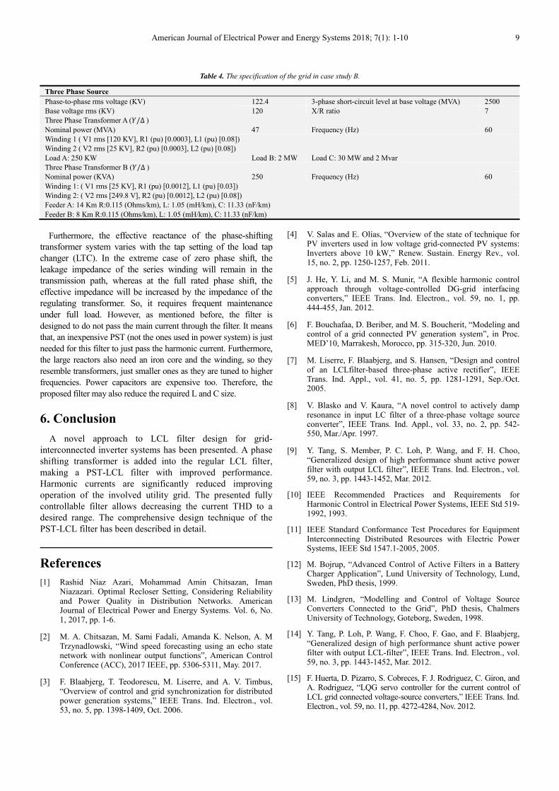
Grid structure in case study B is shown in Figure 10. Table
4 lists specifications of the grid. Comparative FFT analysis
for the LCL and PST-LCL filters is illustrated in Figure 11.
The step-by-step design of the PST-LCL is outlined
subsequently. System specifications are: ;1 ;< 250kW, D< 249V , 482V , =1? 1980Hz, H> 2. 60rad/s, x = 0.05, and I^ 20% , Consequently, the
base impedance and capacitance are B1 0.25Ω , and
10.6mF. Assuming the 10% allowed ripple, Eq. (15)
yields 1.36 mH. In order to be within the limit of 5% of
the base value of CB, the maximum capacitor value, Cf, is set
to 0.53 mF. For the desired attenuation factor, is found
from Eq. (19) to be 0.073 mH. Substituting the calculated
parameters of , , and into Eq. (21) gives H@A1 5218 Hz, which meets condition (22). Eq. (23) determines
the damping resistance 0.12Ω . AngleΦ equals 40 ,

8 Mohammad Amin Chitsazan and Andrzej M Trzynadlowski: Phase Shifting Transformer-LCL
(PST-LCL) Filter: Modeling and Analysis
making yC 3.47.The phase angle of the branch is51.64 and, from Eq. (24), the phase angle of the PST
is 55.11. The THD in presence of the LCL filter is 5.75%, and it
decreases to 3.6% for the PST-LCL one. Figure 11 also
shows waveforms of voltage and current in the inverter. It
can be observed that harmonic currents in the later filter have
been considerably decreased. It should be mentioned that in
power system, along all advantages of using the PST, it is not
inexpensive and it is only used if it is economical. Therefore, the
main application of the PST is in power flow (or loop flow)
control or protection.
Figure 10. Grid structure in case study B.
Figure 11. Case B. Currents injected into grid – FFTs and waveforms: (a) LCL filter, (b) PST-LCL filter.
American Journal of Electrical Power and Energy Systems 2018; 7(1): 1-10 9
Table 4. The specification of the grid in case study B.
Three Phase Source
Phase-to-phase rms voltage (KV) 122.4 3-phase short-circuit level at base voltage (MVA) 2500
Base voltage rms (KV) 120 X/R ratio 7
Three Phase Transformer A (§/Δ) Nominal power (MVA) 47 Frequency (Hz) 60
Winding 1 ( V1 rms [120 KV], R1 (pu) [0.0003], L1 (pu) [0.08])
Winding 2 ( V2 rms [25 KV], R2 (pu) [0.0003], L2 (pu) [0.08])
Load A: 250 KW Load B: 2 MW Load C: 30 MW and 2 Mvar
Three Phase Transformer B (§/Δ)
Nominal power (KVA) 250 Frequency (Hz) 60
Winding 1: ( V1 rms [25 KV], R1 (pu) [0.0012], L1 (pu) [0.03])
Winding 2: ( V2 rms [249.8 V], R2 (pu) [0.0012], L2 (pu) [0.08])
Feeder A: 14 Km R:0.115 (Ohms/km), L: 1.05 (mH/km), C: 11.33 (nF/km)
Feeder B: 8 Km R:0.115 (Ohms/km), L: 1.05 (mH/km), C: 11.33 (nF/km)
Furthermore, the effective reactance of the phase-shifting
transformer system varies with the tap setting of the load tap
changer (LTC). In the extreme case of zero phase shift, the
leakage impedance of the series winding will remain in the
transmission path, whereas at the full rated phase shift, the
effective impedance will be increased by the impedance of the
regulating transformer. So, it requires frequent maintenance
under full load. However, as mentioned before, the filter is
designed to do not pass the main current through the filter. It means
that, an inexpensive PST (not the ones used in power system) is just
needed for this filter to just pass the harmonic current. Furthermore,
the large reactors also need an iron core and the winding, so they
resemble transformers, just smaller ones as they are tuned to higher
frequencies. Power capacitors are expensive too. Therefore, the
proposed filter may also reduce the required L and C size.
6. Conclusion
A novel approach to LCL filter design for grid-
interconnected inverter systems has been presented. A phase
shifting transformer is added into the regular LCL filter,
making a PST-LCL filter with improved performance.
Harmonic currents are significantly reduced improving
operation of the involved utility grid. The presented fully
controllable filter allows decreasing the current THD to a
desired range. The comprehensive design technique of the
PST-LCL filter has been described in detail.
References
[1] Rashid Niaz Azari, Mohammad Amin Chitsazan, Iman Niazazari. Optimal Recloser Setting, Considering Reliability and Power Quality in Distribution Networks. American Journal of Electrical Power and Energy Systems. Vol. 6, No. 1, 2017, pp. 1-6.
[2] M. A. Chitsazan, M. Sami Fadali, Amanda K. Nelson, A. M Trzynadlowski, “Wind speed forecasting using an echo state network with nonlinear output functions”, American Control Conference (ACC), 2017 IEEE, pp. 5306-5311, May. 2017.
[3] F. Blaabjerg, T. Teodorescu, M. Liserre, and A. V. Timbus, “Overview of control and grid synchronization for distributed power generation systems,” IEEE Trans. Ind. Electron., vol. 53, no. 5, pp. 1398-1409, Oct. 2006.
[4] V. Salas and E. Olías, “Overview of the state of technique for PV inverters used in low voltage grid-connected PV systems: Inverters above 10 kW,” Renew. Sustain. Energy Rev., vol. 15, no. 2, pp. 1250-1257, Feb. 2011.
[5] J. He, Y. Li, and M. S. Munir, “A flexible harmonic control approach through voltage-controlled DG-grid interfacing converters,” IEEE Trans. Ind. Electron., vol. 59, no. 1, pp. 444-455, Jan. 2012.
[6] F. Bouchafaa, D. Beriber, and M. S. Boucherit, “Modeling and control of a grid connected PV generation system”, in Proc. MED’10, Marrakesh, Morocco, pp. 315-320, Jun. 2010.
[7] M. Liserre, F. Blaabjerg, and S. Hansen, “Design and control of an LCLfilter-based three-phase active rectifier”, IEEE Trans. Ind. Appl., vol. 41, no. 5, pp. 1281-1291, Sep./Oct. 2005.
[8] V. Blasko and V. Kaura, “A novel control to actively damp resonance in input LC filter of a three-phase voltage source converter”, IEEE Trans. Ind. Appl., vol. 33, no. 2, pp. 542-550, Mar./Apr. 1997.
[9] Y. Tang, S. Member, P. C. Loh, P. Wang, and F. H. Choo, “Generalized design of high performance shunt active power filter with output LCL filter”, IEEE Trans. Ind. Electron., vol. 59, no. 3, pp. 1443-1452, Mar. 2012.
[10] IEEE Recommended Practices and Requirements for Harmonic Control in Electrical Power Systems, IEEE Std 519-1992, 1993.
[11] IEEE Standard Conformance Test Procedures for Equipment Interconnecting Distributed Resources with Electric Power Systems, IEEE Std 1547.1-2005, 2005.
[12] M. Bojrup, “Advanced Control of Active Filters in a Battery Charger Application”, Lund University of Technology, Lund, Sweden, PhD thesis, 1999.
[13] M. Lindgren, “Modelling and Control of Voltage Source Converters Connected to the Grid”, PhD thesis, Chalmers University of Technology, Goteborg, Sweden, 1998.
[14] Y. Tang, P. Loh, P. Wang, F. Choo, F. Gao, and F. Blaabjerg, “Generalized design of high performance shunt active power filter with output LCL-filter”, IEEE Trans. Ind. Electron., vol. 59, no. 3, pp. 1443-1452, Mar. 2012.
[15] F. Huerta, D. Pizarro, S. Cobreces, F. J. Rodriguez, C. Giron, and A. Rodriguez, “LQG servo controller for the current control of LCL grid connected voltage-source converters,” IEEE Trans. Ind. Electron., vol. 59, no. 11, pp. 4272-4284, Nov. 2012.

10 Mohammad Amin Chitsazan and Andrzej M Trzynadlowski: Phase Shifting Transformer-LCL
(PST-LCL) Filter: Modeling and Analysis
[16] T. C. Y. Wang, Z. Ye, G. Sinha, and X. Yuan, “Output filter design for a grid-interconnected three-phase inverter”, in Proc. PESC’03, Acapulco, Mexico, pp. 779-784, Jun. 2003.
[17] J. R. Espinoza, G. Joos, E. Araya, L. A. Moran, and D. Sbarbaro, “Decoupled control of PWM active-front rectifiers using only dc bus sensing”, in Proc. of IAS 2000 Conf., Rome, Italy, pp. 2169-2176, Oct. 2000.
[18] P. Channegowda and V. John, “Filter optimization for grid interactive voltage source inverters”, IEEE Trans. Ind. Electron., vol. 57, no. 12, pp. 4106-4114, Dec. 2010.
[19] A. M. Hava, T. A. Lipo, and W. L. Erdman, “Utility interface issues for line connected PWM voltage source converters: a comparative study”, in Proc. of APEC '95, Dallas (USA), pp. 125-132, March 1995.
[20] S. Chandrasekaran, D. Borojevic, and D. K. Lindner, “Input filter interaction in three phase AC-DC converters”, in Proc. of PESC 99, Charleston (USA), vol. 2, pp. 987-992, Jun./Jul. 1999.
[21] M. A. Chitsazan, A. M Trzynadlowski, “State estimation of power systems with interphase power controllers using the WLS algorithm”, Energy Conversion Congress and Exposition (ECCE), 2016 IEEE, pp. 1-5, Sep. 2016.
[22] M. A. Chitsazan, M. S. Fadali, A. M Trzynadlowski, “State estimation of IEEE 14 bus with unified interphase power controller (UIPC) using WLS method”, Energy Conversion Congress and Exposition (ECCE), 2017 IEEE, pp. 2903-2908, Oct. 2017.
[23] M. A. Chitsazan, A. M Trzynadlowski, “Harmonic mitigation in interphase power controllers using passive filter-based phase shifting transformer”, Energy Conversion Congress and Exposition (ECCE), 2016 IEEE, pp. 1-5, Sep. 2016.
[24] V. Sarfi, H. Livani, “A novel multi-objective security-constrained power management for isolated microgrids in all-electric ships”, Electric Ship Technologies Symposium (ESTS), 2017 IEEE, pp. 148-155, Aug. 2017.
[25] V. Sarfi, I. Niazazari, and H. Livani, “Multiobjective fireworks optimization framework for economic emission dispatch in microgrids”, North American Power Symposium (NAPS), 2016, pp. 1-6, Nov. 2016.
[26] U. N. Khan and T. S. Sidhu, “A phase-shifting transformer protection technique based on directional comparison approach”, IEEE Trans. on Power Delivery, vol. 29, no. 5, pp. 2315-2323, Sep. 2014.
[27] J. Bladow and A. Montoya, “Experiences with parallel EHV shifting transformers”, IEEE Trans. on Power Delivery, vol. 6, no. 3, pp. 1096-1100, July 1991.
[28] M. A. Chitsazan, G. Gharehpetian, and M. Arbabzadeh, “Application of voltage source convector in interphase power controller”, in Proc. of WCECS’12, San Francisco, CA, vol. 2, pp. 1-6,. Oct. 2012.
[29] P. Bresesti, M. Sforna, V. Allegranza, D. Canever, and R. Vailati, “Application of phase shifting transformers for a secure and efficient operation of the interconnection corridors”, in Proc. IEEE Power Eng. Soc. Gen. Mtg., Denver, CO, vol. 2, pp. 1192-1197, Jun. 2004.
[30] J. Verboomen, D. V. Hertem, P. H. Schavemaker, W. L. Kling, and R. Belmans, “Phase shifting transformers: principles and applications”, in Proc. FPS’05, Amsterdam, Netherlands, pp. 1-6, Nov. 2005.
[31] A. Reznik, M. G. Simoes, A. Al-Durra, S. M. Muyeen, “Filter design and performance analysis for grid-interconnected systems”, IEEE Trans. on Ind. Appl., vol. 50, no. 2, pp. 1225, 1232, March-April 2014.
[32] H. Cha and T.-K. Vu, “Comparative analysis of low-pass output filter for single-phase grid-connected photovoltaic inverter,” in Proc. APEC’10, Palm Springs, CA, pp. 1659-1665, Feb. 2010.
[33] S. V. Araujo, A. Engler, B. Sahan, and F. Antunes, "LCL filter design for grid-connected NPC inverters in offshore wind turbines," in Proc. ICPE '07, Daegu, S. Korea, pp. 1133-1138, Oct. 2007.
[34] V. H. Prasad, “Average Current Mode Control of a Voltage Source Inverter Connected to the Grid: Application to Different Filter Cells”, M. S. thesis, Dept. Elect. Eng., Virginia Polytech. Inst. State Univ., Blacksburg, VA, USA, 1997.
[35] R. W. Erickson, D. Maksimovic, Fundamentals of Power Electronics, 2nd Ed., Kluwer Academic Publishers, 2001.
[36] D. E. Rice, “A detailed analysis of six-pulse converter harmonic currents” IEEE Trans. Ind. Appl., vol. 30, no. 2, pp. 294-304, March/April, 1994.
[37] M. Grötzbach, and R. Redmann, “Line current harmonics of VS1-fed adjustable-speed drives,” IEEE Trans. Ind. Appl., vol. 36, no. 2, pp. 683-690, March/April, 2000.
[38] C. Rech and J. R. Pinheiro, “Line current harmonics reduction in hybrid multilevel converters using phase-shifting transformers,” in Proc. PESC’04, Aachen Germany, pp. 2565-2571, Jun. 2004.
[39] G. M. Carvajal, G. O. Plata, W. G. Picon, and J. C. C. Velasco, “Investigation of phase shifting transformers in distribution systems for harmonics mitigation”, in Proc. PSC’14, Clemson, NC, pp. 1-5, Mar. 2014.
[40] S. Ratanapanachote, M. Kang, and P. N. Enjeti, “Auto-connected electronic phase-shifting transformer concept for reducing harmonic generated by nonlinear loads in electric power distribution system,” in Proc. PESC’01, Vancouver, Canada, vol. 2, pp. 1030-1035, Jun. 2001.
[41] D. A. Paice, “Power Electronic Converter Harmonics Multipulse Methods for Clean Power”, IEEE Press, 1996.
[42] Mohammad Amin Chitsazan, Andrzej M. Trzynadlowski. A New Approach to LCL Filter Design for Grid-Connected PV Sources. American Journal of Electrical Power and Energy Systems. Vol. 6, No. 4, 2017, pp. 57-63.
[43] Mohammad Amin Chitsazan, Andrzej M. Trzynadlowski, Harmonic Mitigation in Three-Phase Power Networks with Photovoltaic Energy Sources, American Journal of Electrical Power and Energy Systems. Vol. 6, No. 5, 2017, pp. 72-78.


