PH10FP KCl Refillable pH Sensor - web · PDF fileSC10XB Conductivity Sensor for SC100 IM 12...
22
User’s Manual IM 12B11C01-01E Model PH10FP KCl Refillable pH Sensor IM 12B11C01-01E 1st Edition
Transcript of PH10FP KCl Refillable pH Sensor - web · PDF fileSC10XB Conductivity Sensor for SC100 IM 12...
User’sManual
IM 12B11C01-01E
Model PH10FPKCl Refillable pH Sensor
IM 12B11C01-01E1st Edition

i
Safety Precautions
IM 12B11C01-01E
IM 12B11C01-01E1st Edition: Apr. 2003 (YK)All Rights Reserved, Copyright © 2003, Yokogawa Electric Corporation
r IntroductionThis instruction manual covers the PH10FP KCl Refillable pH sensor for the PH100;this is used mounted in the PH10HLD Immersion holder. Other related EXA100 seriesitems are described in the following manuals:
T000.eps
Model name Manual Name IM No.
PH100 Panel Mount pH Converter IM 12 B11A01-01E
OR100 Panel Mount ORP Converter IM 12 C11A01-01E
SC100 Panel Mount Conductivity Converter IM 12 D11A01-01E
PH10RP KCl Replenish-free pH Sensor IM 12 B11C02-01E
OR10FP KCl Refillable ORP Sensor IM 12 C11C01-01E
OR10RP KCl Replenish-free ORP Sensor IM 12 C11C02-01E
SC10XB Conductivity Sensor for SC100 IM 12 D11C01-01E
PH10HLD Immersion Holder for EXA100 IM 12 B11D01-01E
PH10HG Guide-pipe Holder for EXA100 IM 12 B11D02-01E
WTB100 Terminal Box for EXA100 IM 12 B11E01-01E
WF100 Extension Cable for EXA100 IM 12 B11F01-01E

IM 12B11C01-01Eii
r For the safe use of this equipment(1) About This Manual
• This manual should be passed on to the end user.• The contents of this manual are subject to change without prior notice.• The contents of this manual shall not be reproduced or copied, in part or in whole,
without permission.• This manual explains the functions contained in this product, but does not warrant that
they will suit the particular purpose of the user.• Every effort has been made to ensure accuracy in the preparation of this manual.
However, should any errors or omissions come to the attention of the user, pleasecontact the nearest Yokogawa Electric representative or sales office.
• This manual does not cover the special specifications. This manual may be leftunchanged on any change of specification, construction or parts when the change doesnot affect the functions or performance of the product.
• If the product is used in a manner not specified in this manual, the safety of thisproduct may be impaired.
(2) Safety and Modification Precautions
• Follow the safety precautions in this manual when using the product to ensure protec-tion and safety of personnel, product and system containing the product.
(3) The following safety symbols are used on the product as well as in this manual.
DANGER
This symbol indicates that the operator must follow the instructions laid out in thismanual in order to avoid the risk of personnel injury, electric shock, or fatalities. Themanual describes what special care the operator must exercise to avoid such risk.
WARNING
This symbol indicates that the operator must refer to the instructions in this manual inorder to prevent the instrument (hardware) or software from being damaged, or a systemfailure from occurring.
CAUTION
This symbol draws attention to information essential for understanding the operation andfunctions.
TipThis symbol gives information that complements the current topic.
SEE ALSOThis symbol identifies a source to which to refer.
Protective Ground Terminal
Function Ground Terminal (Do not use this terminal as the protective groundterminal.)
Alternating current
iii
Safety Precautions
IM 12B11C01-01E
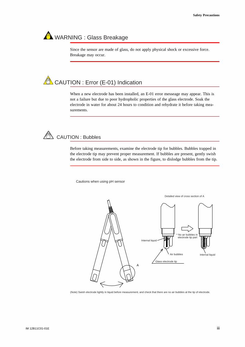
WARNING : Glass Breakage
Since the sensor are made of glass, do not apply physical shock or excessive force.Breakage may occur.
CAUTION : Error (E-01) Indication
When a new electrode has been installed, an E-01 error messeage may appear. This isnot a failure but due to poor hydropholic properties of the glass electrode. Soak theelectrode in water for about 24 hours to condition and rehydrate it before taking mea-surements.
CAUTION : Bubbles
Before taking measurements, examine the electrode tip for bubbles. Bubbles trapped inthe electrode tip may prevent proper measurement. If bubbles are present, gently swishthe electrode from side to side, as shown in the figure, to dislodge bubbles from the tip.
A
(Note) Swish electrode lightly in liquid before measurement, and check that there are no air bubbles at the tip of electrode.
Cautions when using pH sensor
Detailed view of cross section of A
Internal liquid
* No air bubbles in electrode tip part
Internal liquid Air bubbles
Glass electrode tip

IM 12B11C01-01Eiv
r After-sales Warrantyd During the warranty period, for repair under warranty carry or send the product to the
local sales representative or service office. Yokogawa will replace or repair anydamaged parts and return the product to you.
d Before returning a product for repair under warranty, provide us with the modelname and serial number and a description of the problem. Any diagrams or dataexplaining the prpoblem would also be appreciated.
d If we replace the product with a new one, we won’t provide you with a repair report.
d Yokogawa warrants the product for the period stated in the pre-purchase quotation.Yokogawa shall conduct defined warranty service based on its standard. When thecustomer site is located outside of the service area, a fee for dispatching the mainte-nance engineer will be charged to the customer.
d In the following cases, customer will be charged repair fee regardless of warrantyperiod.
• Failure of components which are out of scope of warranty stated in instructionmanual.
• Failure caused by usage of software, hardware or auxiliary equipment, whichYokogawa Electric did not supply.
• Failure due to improper or insufficient maintenance by user.
• Failure due to modification, misuse or outside-of-specifications operation whichYokogawa does not authorize.
• Failure due to power supply (voltage, frequency) being outside specifications orabnormal.
• Failure caused by any usage out of scope of recommended usage.
• Any damage from fire, earthquake, storms and floods, lightning, disturbances, riots,warfare, radiation and other natural changes.
d Yokogawa does not warrant conformance with the specific application at the usersite. Yokogawa will not bear direct/indirect responsibility for damage due to a specificapplication.
d Yokogawa Electric will not bear responsibility when the user configures the productinto systems or resells the product.
d Maintenance service and supplying repair parts will be covered for five years afterthe production ends. For repair for this product, please contact the nearest sales officedescribed in this instruction manual.

vIM 12B11A01-01E
Contents
r Introduction ...................................................................................................................... i
r For the safe use of this equipment ................................................................................ ii
r After-sales Warranty ..................................................................................................... iv
1. Specification ................................................................................................................ 1-1
1.1 Standard Specifications ................................................................................... 1-11.2 Model and Suffix code .................................................................................... 1-21.3 External Dimensions ....................................................................................... 1-2
2. Installation .................................................................................................................. 2-1
2.1 Preparation for Installation ............................................................................. 2-12.1.1 Checking for Damage .............................................................................. 2-12.1.2 Mounting in a Holder .............................................................................. 2-12.1.3 Installing Associated Equipment ............................................................. 2-1
2.2 Requirements for mounting the pH sensor in the immersion holder ............. 2-22.3 pH Sensor Cable Wiring Overview ................................................................ 2-6
2.3.1 When connecting to a WTB100 terminal box ........................................ 2-62.3.2 When connecting to an EXA PH100 pH converter ................................ 2-8
3. Using the Sensor ......................................................................................................... 3-1
3.1 Operation and Periodic Maintenance .............................................................. 3-13.1.1 Calibration with Standard Solution ......................................................... 3-23.1.2 Washing of glass electrode and liquid junction ...................................... 3-2 3.1.3 Topping up internal KCl solution in electrode. ...................................... 3-2
3.2 Replacement of consumables .......................................................................... 3-3
Revision Record .................................................................................................................... i

IM 12B11A01-01Evi

IM 12B11C01-01E 1-1
1. Specification
1. Specification
The compact, easy-to-use KCl Refillable PH10FP pH sensor is mounted in a PH10HLDImmersion holder and used with EXA100 series instruments.
1.1 Standard SpecificationsMeasurement: Hydrogen ion concentration (pH) of a solutionMeasurement principle: Glass electrode methodSensor type: KCl Refillable typeMeasuring range: 0 to 14 pHInstallation: Incorporated in PH10HLD Immersion HolderSample temperature range : 0 to 70 8CSample pressure : Atmospheric pressure (depth: 3 m max.)Sample flow rate : 2 m/s max.Sample conductivity : 50 m S/cm or greaterTemperature detection element : Pt1000
Wetted part materials:Polypropylene, rigid PVC resin, silicone rubber, glass, ceramics, chlorinated polyeth-ylene rubber (cable sheath)
Cable length:3, 5, 10 m (up to 50 m with sensor cable included when WTB100 using terminal box)
Weight: Approx. 300g (3 m), 450g (5 m), 800g (10 m)
Other related instruments:WTB100 Terminal Box and WF100 Extension Cable:
Up to 50 m with sensor cable includedPH10HLD Immersion HolderWetted part materials:
Polypropylene (holder), polyethylene (spacer), silicone rubber (gasket), ethylenepropylene rubber (cover)
IM 12B11C01-01E1-2
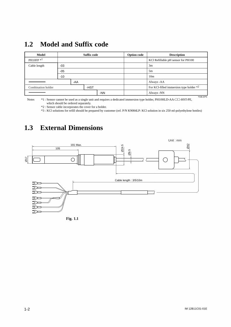
1.2 Model and Suffix code
T03E.EPS
-03
-05
-10
-AA
-HST
-NN
KCl Refillable pH sensor for PH100
3m
5m
10m
Always -AA
For KCl-filled immersion type holder *2
Always -NN
Model Suffix code Option code Description
PH10FP *1
Cable length
Combination holder
Notes *1 : Sensor cannot be used as a single unit and requires a dedicated immersion type holder, PH10HLD-AA-hh-HST-PE, which should be ordered separately.
*2 : Sensor cable incorporates the cover for a holder. *3 : KCl solutions for refill should be prepared by customer (ref. P/N K9084LP: KCl solution in six 250 ml-polyethylene bottles)
1.3 External Dimensions
Cable length : 3/5/10m
105
\17
\24
.5
\6.
5
\42191 Max.
Unit : mm
Fig. 1.1
IM 12B11C01-01E 2-1
2. Installation
2. Installation
2.1 Preparation for Installation
2.1.1 Checking for Damage
The PH10FP KCl Refillable pH sensor is carefully packed to avoid damage duringshipment. However, when you receive it, you should carefully unpack it and check forvisible damage.
2.1.2 Mounting in a Holder
The PH10FP KCI-Refillable pH sensor is mounted in the PH10HLD Immersion holder.Check that the holder is ready for the sensor to be installed.
2.1.3 Installing Associated Equipment
Check that associated equipment such as the WTB100 terminal box and PH100 pHconverter is installed and connected.
IM 12B11C01-01E2-2
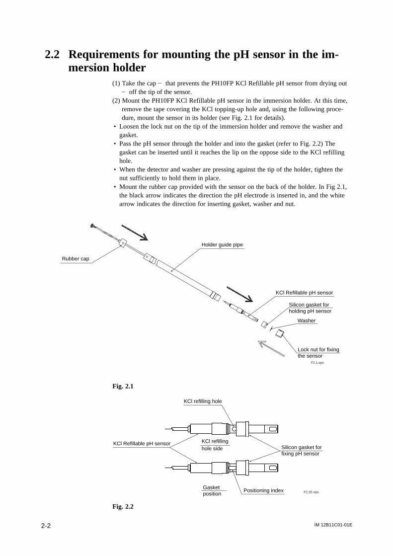
2.2 Requirements for mounting the pH sensor in the im-mersion holder
(1) Take the cap ] that prevents the PH10FP KCl Refillable pH sensor from drying out] off the tip of the sensor.
(2) Mount the PH10FP KCl Refillable pH sensor in the immersion holder. At this time,remove the tape covering the KCl topping-up hole and, using the following proce-dure, mount the sensor in its holder (see Fig. 2.1 for details).
• Loosen the lock nut on the tip of the immersion holder and remove the washer andgasket.
• Pass the pH sensor through the holder and into the gasket (refer to Fig. 2.2) Thegasket can be inserted until it reaches the lip on the oppose side to the KCl refillinghole.
• When the detector and washer are pressing against the tip of the holder, tighten thenut sufficiently to hold them in place.
• Mount the rubber cap provided with the sensor on the back of the holder. In Fig 2.1,the black arrow indicates the direction the pH electrode is inserted in, and the whitearrow indicates the direction for inserting gasket, washer and nut.
F2.1.eps
Rubber cap
Holder guide pipe
KCl Refillable pH sensor
Silicon gasket forholding pH sensor
Washer
Lock nut for fixingthe sensor
Fig. 2.1
F2.2E.eps
KCl refilling hole
KCl Refillable pH sensorSilicon gasket forfixing pH sensor
Gasketposition
Positioning index
KCl refillinghole side
Fig. 2.2
IM 12B11C01-01E 2-3
2. Installation
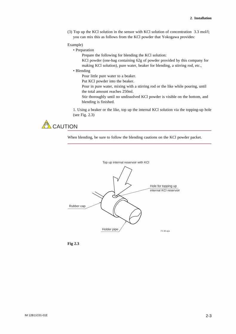
(3) Top up the KCl solution in the sensor with KCl solution of concentration 3.3 mol/l;you can mix this as follows from the KCl powder that Yokogawa provides:
Example)• Preparation
Prepare the following for blending the KCl solution:KCl powder (one-bag containing 62g of powder provided by this company formaking KCl solution), pure water, beaker for blending, a stirring rod, etc.,
• BlendingPour little pure water to a beaker.Put KCl powder into the beaker.Pour in pure water, mixing with a stirring rod or the like while pouring, untilthe total amount reaches 250ml.Stir thoroughly until no undissolved KCl powder is visible on the bottom, andblending is finished.
1. Using a beaker or the like, top up the internal KCl solution via the topping-up hole(see Fig. 2.3)
CAUTION
When blending, be sure to follow the blending cautions on the KCl powder packet.
F2.3E.eps
Hole for topping up internal KCl reservoir
Top up internal reservoir with KCl
Rubber cap
Holder pipe
Fig 2.3

IM 12B11C01-01E2-4
2. Note the following cautions when topping up the KCl.
CAUTION
Take care to rotate the cap so that the filling holes in the holder and cap are aligned (i.e.cap hole is not covered).
F2.4E.eps
Take care to rotate the cap so that the filling holes in the holder and cap are aligned (i.e. cap hole is not covered).
Fig 2.4
3. Take care that spray from measured liquid does not enter refilling hole.4. Be sure to keep the level of the 3.3 mol/l KCl electrolyte above the level of the
measured liquid.
F2.5E.eps
Water (measured liquid) surface
Height of internal KCl solution above water (measured liquid) level
PH10FPKCl refillable pH sensor
Should be high enough above surface that spray from measured liquid does not enter refilling hole.
Fig 2.5
IM 12B11C01-01E 2-5
2. Installation
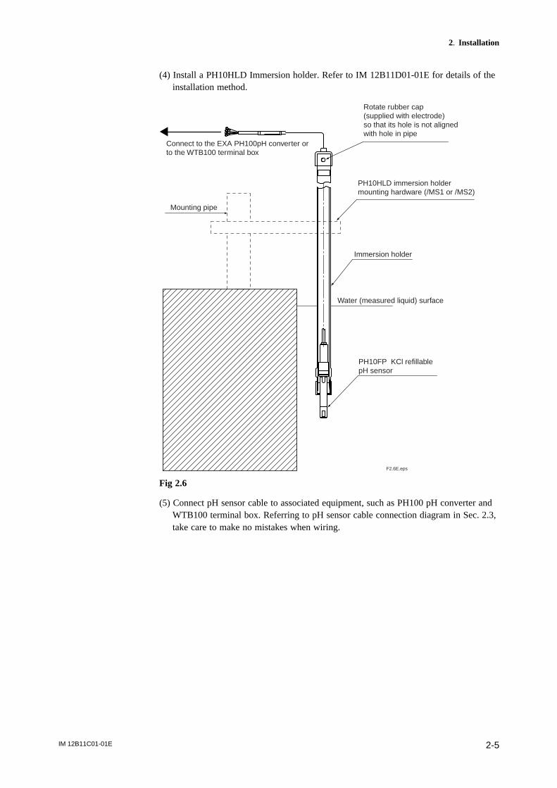
(4) Install a PH10HLD Immersion holder. Refer to IM 12B11D01-01E for details of theinstallation method.
F2.6E.eps
Connect to the EXA PH100pH converter or to the WTB100 terminal box
Rotate rubber cap (supplied with electrode) so that its hole is not aligned with hole in pipe
PH10HLD immersion holder mounting hardware (/MS1 or /MS2)
Immersion holder
Mounting pipe
Water (measured liquid) surface
PH10FP KCl refillable pH sensor
Fig 2.6
(5) Connect pH sensor cable to associated equipment, such as PH100 pH converter andWTB100 terminal box. Referring to pH sensor cable connection diagram in Sec. 2.3,take care to make no mistakes when wiring.

IM 12B11C01-01E2-6
2.3 pH Sensor Cable Wiring Overview
CAUTION
Separate pH sensor cable wiring as far as possible from power supply and groundwiring.
2.3.1 When connecting to a WTB100 terminal box
(1) Open wiring hole in terminal box.On the bottom of the terminal box you can see a circular hole for wiring (covered bya blind plate). Place the tip of a screwdriver or the like in the center of the blindhole, and hit it with a hammer or the like to punch out the blind plate.
F2.7E.eps
Use a sharp tool (e.g. a Phillips screwdriver etc.)
Hole for pulling in center cables
Hole for extension cables
Fig 2.7(2) Loosen two screws of the front of the terminal box, and remove the cover.(3) Connect sensor cable to terminals. First, remove nut from cable gland and pull in
cable via wiring hole. After passing cable through nut, check label on each core ofcable, and connect to the corresponding terminal.
F2.8E.eps
Attach nut in direction of arrow. (In order to index with lock washer)
Nut
Gasket
Body
Nut
Fig 2.8

IM 12B11C01-01E 2-7
2. Installation
(4) Attach cable gland to wiring hole. Screw up nut to predetermined position, andtighten gland securely. Packing gland should be loosened so that cable cannot betwisted at this time. After gland connection to body is tight, tighten packing glandsecurely so that humidity can not enter. However, keep in mind that screwing uppacking gland too tight will damage the cable.
F2.9E.eps
QQQQQQ
Terminal marking Color of cable core
GE red (GE)
S yellow (S)
RE brown (RE) (2 wires)
SE green (SE)
T1 white (T1)
T2 black (T2)
Fig 2.9 Example of wiring to a terminal box,
(5) When the wiring work is completed, replace the cover of the terminal box andtighten firmly. In addition, check that neither dirt nor water drops are adhering towaterproofing packing of case part.
IM 12B11C01-01E2-8
2.3.2 When connecting to an EXA PH100 pH converter
Connection panel mount EXA PH100 pH converter as follows:
(1) Remove the shielding cover (which covers sensor cable connection terminals) on theback of the EXA PH100. As the shielding cover is fixed with two screws, you needto loosen these screws.
(2) Connect sensor cables to appropriate terminals.For details, see IM 12B11A01-01E for wiring of panel mount pH converter.
pH converter terminal no. Color of PH10FP, and PH10RP pH sensor cable core
11 (do not use)
12 (GE) red
13 (S) yellow
14 (RE) brown:2 wires
15 (do not use)
16 (SE) green
17 (T1) white
18 (T2) black
(3) Fix sensor cable in place using a wiring clamp.(4) Replace shielding cover removed in step (1).

IM 12B11C01-01E 3-1
3. Using the Sensor
3. Using the Sensor
3.1 Operation and Periodic Maintenance
CAUTION
Since the electrode of the pH sensor is made of glass, it may be broken if force or shockis applied to it, or it is dropped. Please handle it carefully.
CAUTION
There may be air bubbles inside the sensor; if they gather near the tip of the electrode,measurement accuracy may be affected. Check before measurement that there are no airbubbles around tip of electrode. If air bubbles are visible near the tip of the electrode, asshown in the figure below, lightly swish the electrode in liquid to move air bubblesupwards.
A
(Note) Swish electrode lightly in liquid before measurement, and check that there are no air bubbles at the tip of electrode.
Cautions when using pH sensor
Detailed view of cross section of A
Internal liquid
* No air bubbles in electrode tip part
Internal liquid Air bubbles
Glass electrode tip

IM 12B11C01-01E3-2
3.1.1 Calibration with Standard Solution
The emf characteristics of glass pH electrodes varies between electrodes, and varieswhen they get dirty as well as with electrode aging. Be sure to calibrate them with freshstandard solution before use, and also calibrate them periodically to keep error withintolerance. The procedure for calibration with standard liquid is described in Section 6 ofthe pH Converter Manual IM 12B11A01-01E.
Decide the optimum interval for preventive maintenance depending on operatingconditions. Preventive maintenance does not necessarily guarantee that there will be nofailures.
3.1.2 Washing of glass electrode and liquid junction
If a lot of dirt is adhering to glass electrode or liquid junction, measurement errors mayresult. Therefore, the required washing interval will depend on how quickly they becomedirty.
Wash glass electrode and liquid junction as follows:
* If the dirt is colloidal, adhesive substances, microbes, etc., wipe it off with soft tissueetc. Further wash liquid junction with water to remove remaining dirt.
* If the dirt is oily substances, dip in neutral detergent solution in a beaker to remove.* If the dirt is chemical stains, such as caused by adsorption of metal,
dip in weak (about 1-2%) hydrochloric acid for several minutes. (Acid washing)Perform acid washing if the sensor is used to measure high-alkalinity solution, and itsperformance starts to fall off due to chemical dirt adhering to it.
for several
minutes
< Washing at intervals that depend on measured liquid > < Chemical dirt, such as adsorbed metal >
Water
Soft cotton wad or the like
Temperature sensor
Glass electrode
Dilute hydrochloric-acid solution wash in water
3.1.3 Topping up internal KCl solution in electrode.
The amount of KCl solution lost from the liquid junction of the PH10FP pH sensorunder a pressure of 10 kPa (representing a head difference of 1 m between the liquidjunction of the KCl sensor and the surface of the liquid being measured) is 3 ml/daymaximum. Under normal conditions, the 250ml of KCl solution will usually last 3-6months. Periodically check the level of KCl in the sensor, and top up if necessary.
Refer to (3) of 2.2 for the procedure for topping up.
(1) Put one bag of our company’s KCl powder (containing 62g) into a suitable beaker,and dissolve in pure water.
(2) Top up to exactly 250 ml with pure water to make 3.3 mol/l KCl solution.Reference : Clause (3) of Sec. 2.2 describes topping up with KCl and installation inthe immersion holder.

IM 12B11C01-01E 3-3
3. Using the Sensor
3.2 Replacement of consumables
d Replacement of PH10FP KCl Refillable sensorThe PH10FP sensor has limited life. When it can no longer be calibrated withstandard solution, it should be replaced. Refer to the Sec. 2.2 for the installationprocedure.The glass membrane needs to be soaked in water for at least 30 minutes until itscharacteristics stabilize, and after replacing the pH sensor, please be sure to calibrateit with standard solution.
CAUTION
For a new pH electrode, the error code E-01 may be displayed. This does not indicate adefective junction; the electrode may need to be soaked in water for a day before it isready for use.
d Replacing the gasket in the PH10HLD Immersion holderFor the PH10HLD immersion holder, the sealing characteristics of the silicon gasketdo not usually deteriorate if it is unused for a short time, so replacement of the silicongasket alone is usually not required. If, however, deterioration of the silicon gasket isnoticeable, replace it. Use only silicon gaskets supplied by Yokogawa.
dCautions regarding storage of pH sensorBe careful not to allow liquid junction and glass of the pH sensor to dry out.When storing the pH sensor, be sure to attach the protective cap (supplied with itwhen it is shipped) to its tip.If the protective cap has been lost, then store the sensor with its tip immersed in tapwater to keep the glass and liquid junction wet.

IM 12B11C01-01E3-4

Revision Record
Manual Title : Model PH10FP KCl Refillable pH sensor
Manual Number : IM 12B11C01-01E
Edition Date Remark (s)
1st Apr. 2003 Newly published