pH 500/mV 600 Series - hannacan.com · 8 9 INSTALLATION pH 500 and mV 600 offer a multitude of...
33
pH 500/mV 600 Series Panel-mounted, Microprocessor-based Process pH/mV Meters Instruction Manual
-
Upload
vuongtuyen -
Category
Documents
-
view
220 -
download
0
Transcript of pH 500/mV 600 Series - hannacan.com · 8 9 INSTALLATION pH 500 and mV 600 offer a multitude of...

pH 500/mV 600 Series
Panel-mounted,Microprocessor-basedProcess pH/mV Meters
Instruction Manual

32
TABLE OF CONTENTS
PRELIMINARY EXAMINATION . . . . . . . . . . . . . . . . . 4
GENERAL DESCRIPTION. . . . . . . . . . . . . . . . . . . . . 4
FUNCTIONAL DESCRIPTION . . . . . . . . . . . . . . . . . 6
MECHANICAL DIMENSIONS . . . . . . . . . . . . . . . . . 7
SPECIFICATIONS pH 500 & mV 600 . . . . . . . . . . . . 8
INSTALLATION . . . . . . . . . . . . . . . . . . . . . . . . . . . . 9
SETUP MODE . . . . . . . . . . . . . . . . . . . . . . . . . . . 11
CONTROL MODE . . . . . . . . . . . . . . . . . . . . . . . . 17
IDLE MODE . . . . . . . . . . . . . . . . . . . . . . . . . . . . . 22
ANALOG OUTPUT . . . . . . . . . . . . . . . . . . . . . . . . 23
RS 232 COMMUNICATION AND DATA LOGGING 25
CALIBRATION . . . . . . . . . . . . . . . . . . . . . . . . . . . 27
LAST CALIBRATION DATA . . . . . . . . . . . . . . . . . . . 39
STARTUP . . . . . . . . . . . . . . . . . . . . . . . . . . . . . . . 42
FAULT CONDITIONS AND SELFTEST PROCEDURES . 43
pH VALUES AT VARIOUS TEMPERATURES . . . . . . . . 47
ELECTRODE CONDITIONING AND MAINTENANCE . 48
TAKING REDOX MEASUREMENTS . . . . . . . . . . . . . 52
ACCESSORIES . . . . . . . . . . . . . . . . . . . . . . . . . . . 54
WARRANTY . . . . . . . . . . . . . . . . . . . . . . . . . . . . . 60
CE DECLARATION OF CONFORMITY. . . . . . . . . . . 62
All rights are reserved. Reproduction in whole or in part is prohibited without thewritten consent of the copyright owner, Hanna Instruments Inc., 584 Park East Drive,Woonsocket, Rhode Island, 02895 , USA.
Dear Customer,
Thank you for choosing a Hanna Product.
This instruction manual has been written for the followingproducts:
pH 500111 pH Controller with single setpoint, ON/OFFcontrol, analog output
pH 500112 pH Controller with single setpoint, ON/OFFcontrol, RS232 output
pH 500121 pH Controller with single setpoint, propor-tional and ON/OFF control, analog output
pH 500122 pH Controller with single setpoint, propor-tional and ON/OFF control, RS232 output
pH 500211 pH Controller with dual setpoint, ON/OFFcontrol, analog output
pH 500212 pH Controller with dual setpoint, ON/OFFcontrol, RS232 output
pH 500221 pH Controller with dual setpoint, propor-tional and ON/OFF control, analog output
pH 500222 pH Controller with dual setpoint, proportionaland ON/OFF control, RS232 output
mV 600111 ORP Controller with single setpoint, ON/OFFcontrol, analog output
mV 600112 ORP Controller with single setpoint, ON/OFFcontrol, RS232 output
mV 600121 ORP Controller with single setpoint, propor-tional and ON/OFF control, analog output
mV 600122 ORP Controller with single setpoint, propor-tional and ON/OFF control, RS232 output
Please read this instruction manual carefully before usingthe instrument. It will provide you with the necessary infor-mation for the correct use of the instrument, as well as aprecise idea of its versatility.
These instruments are in compliance with directivesEN 50081-1, EN 50082-1 and EN 61010-1.

54
• Temperature compensation of the pH reading (for pH 500Series only).
• Manual temperature setting when the temperature probe isnot inserted or temperature exceeds the upper range.
• Last calibration data internally recorded (non-volatile EE-PROM memory): calibration date and time, pH offset, pHslopes, number of calibration points and correspondentpH values (for pH 500 Series only) or calibration date andtime and the mV calibration points used (for mV 600 Seriesonly).
• Input: pH electrode with BNC connector.
• Output:
- isolated 0-1 mA, 10 KW maximum load (optional);
- isolated 0-20 mA, 750 W maximum load (optional);
- isolated 4-20 mA, 750 W maximum load (optional);
- isolated 0-5 VDC, 1 KW minimum load (optional);
- isolated 1-5 VDC, 1 KW minimum load (optional);
- isolated 0-10 VDC, 1 KW minimum load (optional).
• Real time clock.
PRELIMINARY EXAMINATION
Remove the instrument from the packing material and exam-ine it carefully to make sure that no damage has occurredduring shipping. If there is any noticeable damage, notifyyour Dealer or the nearest Hanna Customer Service Centerimmediately.
Note Save all packing materials until you are sure that the instru-ment functions correctly. Any damaged or defective items mustbe returned in their original packing materials together withthe supplied accessories.
GENERAL DESCRIPTION
The product is a real time microprocessor-based pH/ORPcontroller. It provides accurate measurements, flexibleON/OFF or proportional control capabilities and dualalarm signals.
The system is composed of a case inside which the signalconversion circuitry, the microprocessor circuitry and theoutput power drivers are contained.
MAIN FEATURES OF DIFFERENT MODELS
• Display: large LCD with 4 ½ 17 mm digits and 3 ½10 mm digits.
• LEDs: three (mV 600) or four (pH 500) LEDs are pro-vided for signaling the energizing of relay 1 (a yellowled), relay 2 (a yellow led in pH 500 Series only) andalarm relays (a green and a red LED).
• Relays: 1 or 2 output relays for acid or base dosage (COM,NO and NC contacts) and 1 output relay for alarm condi-tion (COM, NO and NC contacts).
• RS232 isolated communication link (optional).
• Calibration and Setup procedures allowed only throughan unlock password.
• Calibration: for pH 500 Series in 1, 2 or 3 points withbuffers 4.01, 7.01 and 10.01 pH (25 °C); for mV 600Series in 1 or 2 points at 0, 350 and 1900 mV.
• Temperature compensation of the HANNA standard buff-ers (for pH 500 Series only).

76
REAR PANEL
1. RS232 Connection Port (pH500XY2 and mV600XY2 models only)2. Analog Output (pH500XY1 and mV600XY1 models only)3. Power Supply Input4. Alarm Terminal5. Relay 2 - Second Dosing Terminal (pH5002XY models only)6. Relay 1 - First Dosing Terminal7. Connections for Pt 100 Temperature Sensor8. Connection for Electrode Reference9. Connection for Potential Matching Pin
10. BNC Socket for pH or ORP Electrode11. ±5V Power Supply Output
Unplug the meter before starting any electrical connections.
MECHANICAL DIMENSIONS
FRONT VIEW SIDE VIEW
FUNCTIONAL DESCRIPTION
FRONT PANEL
1. Liquid Crystal Display
2. LCD key exits from setup and calibration modes and reverts back tonormal mode (in idle or control phases with the measure-ment on the display). In pH 500 series, during pHcalibration, alternately displays pH buffer value or currenttemperature
3. SETUP key enters setup mode
4. CAL DATA key last calibration data viewing (enters and exits)
5. CAL key initiates and exits calibration mode
6. key increases the blinking digit/letter by one when selecting aparameter. Advances forward while in last calibration dataviewing mode. Increases the temperature setting whentemperature probe is not inserted
7. key decreases the blinking digit/letter by one when selecting aparameter. Reverts backward while in last calibration dataviewing mode. Decreases the temperature setting whentemperature probe is not inserted
8. key moves to the next digit/letter (circular buffer) when select-ing a parameter. Same as key during last calibrationdata viewing mode
9. CFM key confirms current choice (and skips to the next item)
10. LEDs

98
INSTALLATION
pH 500 and mV 600offer a multitude ofpossibilit ies, fromsingle and dual set-points to ON/OFF orproportional dosage,isolated outputs withuser-selectable zoom,bi-directional RS232,recorder outputs inmAmps and volts.
In addition, pH 500and mV 600 are bothequipped with the ex-clusive differentialinput.
In a system with poorgrounding, it ispossible to have aground current flow-ing through thereference junction.This can cause a rapiddegradation of theelectrode. The Hannadifferential inputreduces the likelihoodof ground loops.
See the diagram for arecommended instal-lation.
SPECIFICATIONS pH 500 & mV 600
Range 0.00-14.00 pH (pH 500 Series only)±2000 mV (mV 600 Series only)-9.9 to 120.0 �C
Resolution 0.01 pH (pH 500 Series only)1 mV (mV 600 Series only)0.1 �C
Accuracy ±0.02 pH (pH 500 Series only)(@20°C/68°F) ±2 mV (mV 600 Series only)
±0.5 �C
Typical EMC Deviation ±0.2 pH (pH 500 Series only)±10 mV (mV 600 Series only)±0.5 �C
Installation Category II
Power Supply 230 ±10% VAC or 115 ±10% VAC, 50/60 Hz
Power Consumption 15 VA
Over Current Protection 200 mA 250V FAST FUSE
Max.Oscillation Frequency 4 MHz
Relays 1 and 2 SPDT contact outputs, 5A - 250 VAC, 5A - 30 VDC(resistive load)
Fuse protected: 5A, 250V FUSE
Alarm Relay SPDT contact output, 5A - 250 VAC, 5A - 30 VDC(resistive load)
Fuse protected: 5A, 250V FUSE
Environment 0-50 �C; max 85% R.H. non-condensing
Enclosure single case ½ DIN
Weight approximately 1.6 kg. (3.5 lb.)

1110
SETUP MODE
pH 500 and mV 600 offer a multitude of possibilities fromON/OFF or proportional dosage to analog recorder outputand from alarm to selftest features.
The Setup Mode allows the user to set all needed character-istics of the meter.
The setup mode is entered by pressing SETUPand entering the password when the deviceis in idle or control mode.
Generally speaking, if the password is not inserted the usercan only view the setup parameters (except for password)without modifying them (and the device remains in controlmode). An exception is certain setup items, or flags, whichcan activate special tasks when set and confirmed.
Each setup parameter (or setup item) is assigned a two-digit setup code which is entered and displayed on thesecondary LCD.
The setup codes can be selected after password and CFMare pressed. When CFM is pressed, the current setup itemis saved on EEPROM and the following item is displayed.Whenever LCD is pressed, thedevice reverts back to controlmode. The same is true whenCFM is pressed on the last setupitem.
The possible transitions in setup mode are the following:
ENTERING THE PASSWORD
• Press SETUP to enter the setup mode. The LCD will display“0000” on the upper part and “PAS” on the lower. The firstdigit of the upper part of the LCD will blink.
• Enter the first value of the pass-word by the or keys.
••••• Power Supply: Connect a 3-wire power cableto the terminal strip, while paying attentionto the correct live (L), earth (PE) and neu-tral (N) terminal connections.
Power: 115VAC - 100 mA / 230VAC - 50 mA
Live Contact: fused inside 200 mA.
PE must be connected to ground; leakage current 1mA.
••••• Electrode: Connect the pH or ORP electrode to the BNCsocket (#10 at page 7).To benefit from the differential input, connect the properelectrode wire (if available) or a cable with a potentialmatching pin (groundingbar) to the relevant termi-nal (#9 at page 7).
Note When it is not possible to immerse the Potential Matching Pintogether with the pH electrode in the solution, disable thedifferential input by connecting the Connection for PotentialMatching Pin (#9 at page 7) with the Connection for Elec-trode Reference (#8 atpage 7) with a jumper wire.
••••• Pt 100 Terminals: these contacts (#7 at page 7) connectthe Pt 100 temperature sensor for automatic temperaturecompensation of pH measurement. In the case of shieldedwire, connect the shield to pin 4.
In the case of a 2-wire sensor con-nect the Pt 100 to pins 1 and 3,and short pins 2 and 3 with ajumper wire.
If the Pt 100 has more than 2wires, connect the two wires of oneend to pins 2 and 3 (pin 2 is anauxiliary input to compensate forthe cable resistance) and one wirefrom the other end to pin 1. Leavethe fourth wire unconnected, if present.
••••• Power Supply Output: these terminalsprovide +5V and -5V DC signals tosupply power to amplified electrodes.
NoteNoteNoteNoteNote All cables connected to rear panel should end with cable lugs.

1312
• After confirmation, the selected param-eter is displayed. The user can scrollthrough the parameters by pressing CFM.
In order to directly set another param-eter, press SETUP again and enter thecode or scroll to it by pressing CFM.
The following table lists the setup codes along with the descrip-tion of the specific setup items, their valid values and whetherpassword is required to view that item (“PW” column):
Code Valid Values Default PW
00 Factory ID 0 to 9999 0000 no
01 Process ID 0 to 9999 0000 no
02 Control enable/disable 0: C.M. disabled 0 no1: C.M. enabled
11 Relay 1 mode 0: disabled 0 no(M1) 1: ON-OFF high setpoint
2: ON-OFF low setpoint3: Proportional, high setpoint4: Proportional, low setpoint
12 Relay 1 setpoint 0.00 to 14.00 pH 8.00 pH no(S1) -2000 to 2000 mV 500 mV
13 Relay 1 hysteresis 0.00 to 14.00 pH 1 pH no(H1) 0 to 4000 mV 50 mV
14 Relay 1 deviation 0.50 to 14.00 pH 1 pH no(D1) 25 to 4000 mV 50 mV
21* Relay 2 mode (M2) same as relay 1 0 no
22* Relay 2 setpoint (S2) 0.00 to 14.00 pH 6.00 pH no-2000 to 2000 mV -500 mV
23* Relay 2 hysteresis (H2) 0.00 to 14.00 pH 1 pH no0 to 4000 mV 50 mV
24* Relay 2 deviation (D2) 0.50 to 14.00 pH 1 pH no25 to 4000 mV 50 mV
* Available only in models with two relays
• Then confirm the displayed digit with and move to the next one.
• When the whole password has beeninserted, press CFM to confirm it.
Note The default password is set at “0000”.
• The LCD will display “SET” on theupper part and “c.00” on the lower,allowing the user to edit setup pa-rameters (see table below).
• Enter the code of the parameter you want to set, using thearrow keys as per the password procedure above (e.g.41).
• Confirm the code by pressing CFM and the default or thepreviously memorized value will be displayed with the firstdigit blinking.
Note When the password is not inserted or a wrong password isconfirmed, the display will only show the previously memo-rized value, without blinking (read only mode). In this case,the value cannot be set. Press LCD and start again.
• Enter the desired value using the arrow keys and then pressCFM.
1514
Code Valid Values Default PW
92 EEPROM selftest 0: off 0 yes1: on
93 Relays and LEDs selftest 0: off 0 yes1: on
94 Watchdog selftest 0: off 0 yes1: on
99 Unlock password 0000 to 9999 0000 yes
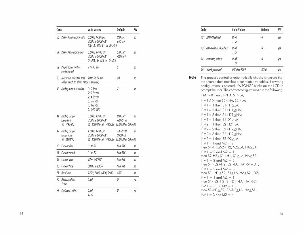
Note The process controller automatically checks to ensure thatthe entered data matches other related variables. If a wrongconfiguration is entered, “WRONG” blinks on the LCD toprompt the user. The correct configurations are the following:
If M1=/ 0 then S1<HA, S1>LA;
If M2=/ 0 then S2<HA, S2>LA;
If M1= 1 then S1-H1>LA;
If M1= 2 then S1+H1<HA;
If M1= 3 then S1+D1<HA;
If M1= 4 then S1-D1>LA;
If M2= 1 then S2-H2>LA;
If M2= 2 then S2+H2<HA;
If M2= 3 then S2+D2<HA;
If M2= 4 then S2-D2>LA;
If M1= 1 and M2 = 2then S1-H1>S2+H2, S2>LA, HA>S1;
If M1 = 2 and M2 = 1then S2-H2>S1+H1, S1>LA, HA>S2;
If M1 = 3 and M2 = 2then S1>S2+H2, S2>LA, HA>S1+D1;
If M1 = 2 and M2 = 3then S1+H1<S2, S1>LA, HA>S2+D2;
If M1 = 4 and M2 = 1then S1<S2–H2, S1–D1>LA, HA>S2;
If M1 = 1 and M2 = 4then S1–H1>S2, S2–D2>LA, HA>S1;
If M1 = 3 and M2 = 4
Code Valid Values Default PW
30 Relay 3 high alarm (HA) 0.00 to 14.00 pH 9.00 pH no-2000 to 2000 mV 600 mVHA>LA, HA>S1 or HA>S2
31 Relay 3 low alarm (LA) 0.00 to 14.00 pH 5.00 pH no-2000 to 2000 mV -600 mVLA<HA, LA<S1 or LA<S2
32 Proportional control 1 to 30 min 5 nomode period
33 Maximum relay ON time 10 to 9999 min 60 no(after which an alarm mode is entered)
40 Analog output selection 0: 0-1mA 2 no1: 0-20 mA2: 4-20 mA3: 0-5 VDC4: 1-5 VDC5: 0-10 VDC
41 Analog output 0.00 to 13.00 pH 0.00 pH nolower limit -2000 to 2000 mV -2000 mV(O_VARMIN) (O_VARMIN< O_VARMAX - (1.00pH or 50mV))
42 Analog output 1.00 to 14.00 pH 14.00 pH noupper limit -2000 to 2000 mV 2000 mV(O_VARMAX) (O_VARMIN< O_VARMAX - (1.00pH or 50mV))
60 Current day 01 to 31 from RTC no
61 Current month 01 to 12 from RTC no
62 Current year 1997 to 9999 from RTC no
63 Current time 00:00 to 23:59 from RTC no
71 Baud rate 1200, 2400, 4800, 9600 4800 no
90 Display selftest 0: off 0 yes1: on
91 Keyboard selftest 0: off 0 yes1: on

1716
CONTROL MODE
The control mode is the normal operational mode for thesemeters. During control mode pH 500 and mV 600 fulfill thefollowing main tasks:
• convert information from pH/ORP and temperature inputsto digital values;
• control relays and generate the analog outputs as deter-mined by the setup configuration, display alarm condition;
• RS232 management.
In addition, pH 500 and mV 600 can log working datathrough RS232 connection. This data includes:
• pH, mV and oC measured values;
• last calibration data;
• setup configuration (also from PC).
The status of the meter is shown by the LED’s on the right
STATUS LEDsControl Alarm Alarm LED (green) Relay LED (yellow) Red LED
OFF - - - - ON OFF ON
ON OFF ON ON or OFF OFF
ON ON OFF ON or OFF Blinking
Meter exits control mode by pressing SETUP or CAL and con-firming the password. Note thatthis command generates a tem-porary exit. To deactivate thecontrol mode definitively, setCONTROL ENABLE to “0” (item # 02).
RELAY MODES
Once enabled, the relays 1 and 2 can be used in four differ-ent modes:1) ON/OFF, high setpoint (acid dosage);2) ON/OFF, low setpoint (base dosage);3) proportional, low setpoint (base dosage, if available);4) proportional, high setpoint (acid dosage, if available).
then S1>S2, S2–D2>LA, HA>S1+D1;
If M1 = 4 and M2 = 3then S2>S1, S1–D1>LA, HA>S2+D2;
where the minimum deviation (D1 or D2) is 0.5 pH (forpH 500) or 25 mV (for mV 600).
Note The password cannot be viewed when SETUP is pressedwithout entering the original password first. The defaultpassword is set at “0000”. In the event that the user forgetsthe password, this can be reset to “0000” by pressing andholding CFM and then pressing LCD and CAL DATA at thesame time when the pH controller is in normal operatingmode (idle or control with measurement displaying).
Note When a wrong setup value is con-firmed, the pH controller does notskip to the next setup item but remainsin the current item displaying a flash-ing “WRONG” indicator until the pa-rameter value is changed by the user (the same is also truefor the setup code selection). In some circumstances, usercannot succeed in setting a parameter to a desired value ifthe related parameters are not changed beforehand; e.g. toset a pH high setpoint to 10.00 the high alarm must be set toa value greater than pH 10.00 first.
Note For code numbers 40, 41, 42, the output is related to pH ormV units depending on the model (pH process meters or mVprocess meters).

1918
PROPORTIONAL CONTROL MODE
The user can vary three different parameters, i.e. the setpoint(S1 or S2), the deviation (D1 or D2) and the proportionalcontrol mode period T
c from 1 to 30 minutes. Duration of the
activated control is directly proportional to the error value(Duty Cycle Control Mode): as the measurement approachessetpoint, the ON period diminishes.
The following graph describes the pH process controller be-havior. Similar graph may apply to the mV controller.
During proportional control the process controller calculatesthe relay activation time at certain moments t
0, t
0+T
c, t
0+2T
c
etc. The ON interval (the shaded areas) is then proportionalto the error amplitude.
For example with S1 representing High SetpointSetpoint (S1) = 7.00 pHDeviation (D1) = 1.00 pHT
c = 1 minute
If measurement > 8.00 pH, then ON all the time.
If measurement = 7.60 pH, then ON for 36 secondsOFF for 24 seconds.
If measurement = 7.10 pH, then ON for 6 secondsOFF for 54 seconds.
The number of strokes per minute of the pump can bechanged only by means of the pump’s command.
Referring to the following diagram (low setpoint) the relay is:
• ALWAYS ON if pH < setpoint-deviation;
• ON proportionally to the errorif setpoint - deviation < pH < setpoint
ON
OFF
14Setpoint +Hysteresis
Setpoint
t0
t0+ T
ct
0+2T
c t0+3T
c
An upper boundary is imposed for acid/base dosage timewhen relays are energized continuously, i.e. when relay worksin ON/OFF mode or in proportional mode but in the lattercase only if the relay is always ON. This parameter can be setthrough setup procedure. When the maximum boundary isreached, an alarm is generated; device stays in alarm condi-tion until relay is de-energized.
ON/OFF CONTROL MODE
Either for mode 1 or 2 (base or acid dosage) the user has todefine the following values through setup:
• relay setpoint (pH/mV value);
• relay hysteresis (pH/mV value).
Connect your device to the COMand NO (Normally Open) or NC(Normally Closed) terminals.
The ON relay state occurs when relay is energized (NO andCOM connected, NC and COM disconnected).
The OFF relay state occurs when relay is de-energized (NOand COM disconnected, NC and COM connected).
The following graphs show relay states along with pH mea-sured value (similar graph can be derived for mV control).
As shown below, a high setpoint relay is activated when themeasured pH exceeds the setpoint and is deactivated when itis below the setpoint value minus hysteresis.
Such a behavior is suitable to control an acid dosing pump.A low setpoint relay as can be seen from the following graphsis energized when the pH value is below the setpoint and isde-energized when the pH value is above the sum of setpointand the hysteresis. The low setpoint relay may be used tocontrol an alkaline dosing pump.
ON
OFF
Setpoint 14Setpoint –Hysteresis
2120
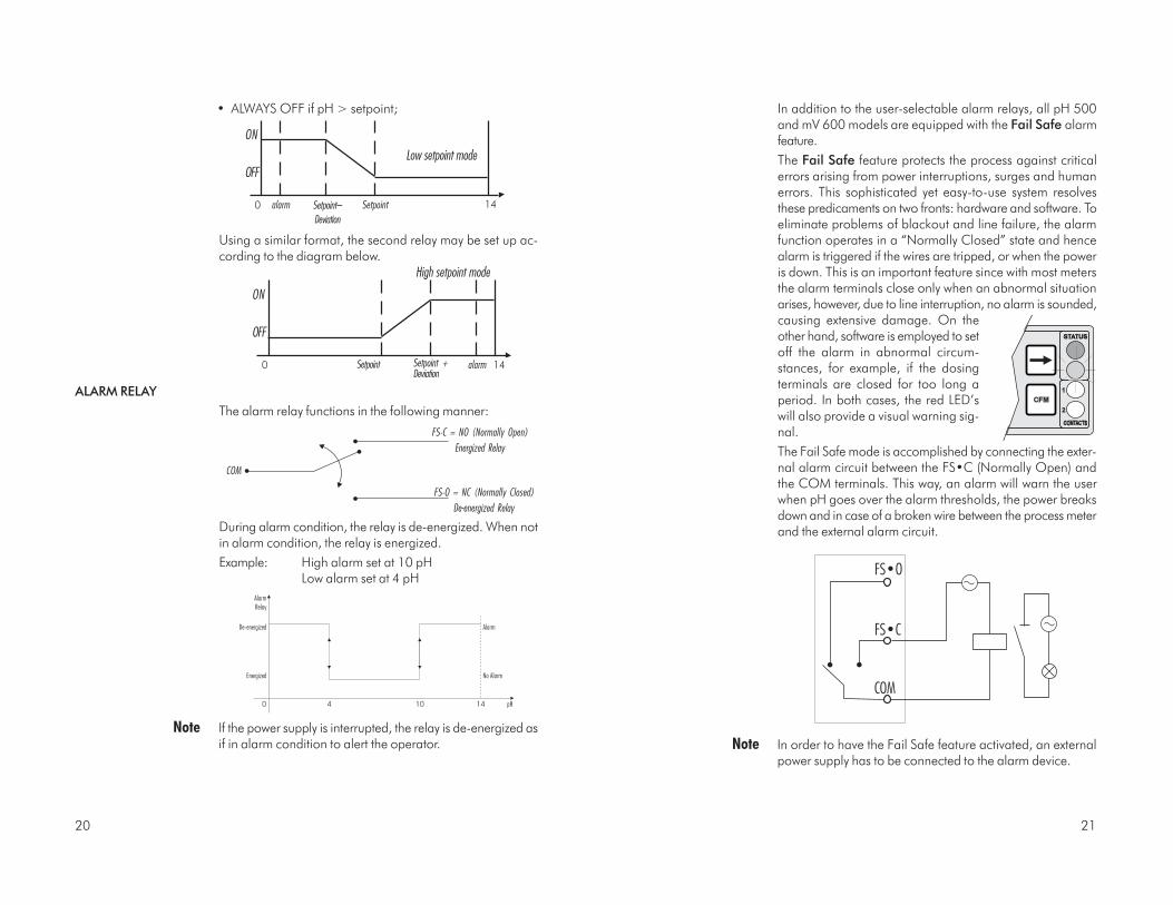
In addition to the user-selectable alarm relays, all pH 500and mV 600 models are equipped with the Fail Safe alarmfeature.
The Fail Safe feature protects the process against criticalerrors arising from power interruptions, surges and humanerrors. This sophisticated yet easy-to-use system resolvesthese predicaments on two fronts: hardware and software. Toeliminate problems of blackout and line failure, the alarmfunction operates in a “Normally Closed” state and hencealarm is triggered if the wires are tripped, or when the poweris down. This is an important feature since with most metersthe alarm terminals close only when an abnormal situationarises, however, due to line interruption, no alarm is sounded,causing extensive damage. On theother hand, software is employed to setoff the alarm in abnormal circum-stances, for example, if the dosingterminals are closed for too long aperiod. In both cases, the red LED’swill also provide a visual warning sig-nal.
The Fail Safe mode is accomplished by connecting the exter-nal alarm circuit between the FS•C (Normally Open) andthe COM terminals. This way, an alarm will warn the userwhen pH goes over the alarm thresholds, the power breaksdown and in case of a broken wire between the process meterand the external alarm circuit.
Note In order to have the Fail Safe feature activated, an externalpower supply has to be connected to the alarm device.
• ALWAYS OFF if pH > setpoint;
Using a similar format, the second relay may be set up ac-cording to the diagram below.
ALARM RELAY
The alarm relay functions in the following manner:
During alarm condition, the relay is de-energized. When notin alarm condition, the relay is energized.
Example: High alarm set at 10 pHLow alarm set at 4 pH
Note If the power supply is interrupted, the relay is de-energized asif in alarm condition to alert the operator.
High setpoint mode
alarm
ON
OFF
0 Setpoint +Deviation
Setpoint 14
ON
OFF
Low setpoint mode
0 alarm Setpoint 14Setpoint–
Deviation
FS•O = NC (Normally Closed)
De-energized Relay
COM
FS•C = NO (Normally Open)
Energized Relay

2322
ANALOG OUTPUT
All models pH 500XY1 and mV 600XY1 are provided with theanalog output feature.
The output is isolated and can be a voltage or a current.
With the recorder, simply connect thecommon port to the ground outputand the second port to the currentoutput or voltage output (dependingon which parameter is being used)as depicted aside.
The type (voltage or current) and the range of the outputanalog signal is selectable through the jumpers on thepower board.
Configurations of the switch are as follows:
Output Switch 1 Switch 2 Switch 3 Switch 4
0-5 VDC, 1-5 VDC OFF ON – – – –
0-10 VDC ON OFF – – – –
0-20 mA, 4-20 mA – – – – ON – –
0-1 mA – – – – OFF – –
Choice between different ranges with the same configura-tion (for example 0-20 mA and 4-20 mA) is achieved viasoftware by entering the setup mode and selecting code40 (see Setup Mode section for exact procedure).
Factory default is switches 1 and 3 closed (ON) and switches2 and 4 open (OFF), i.e. 0-20 mA, 4-20 mA, and 0-10VDC.
In any case, contact the nearest Hanna Customer ServiceCenter for changing of the default configuration.
By default the minimum and maximum values of analogoutput correspond to the minimum and maximum of therange of the meter. For example, for the pH 500 serieswith a selected analog output of 4-20 mA, the default val-ues are 0.00 and 14.00 pH corresponding to 4 and20 mA, respectively.
IDLE MODE
During idle mode the device performs the same tasks as whenit is in control mode except for the relays. The alarm relay isactivated (no alarm condition), the acid and base relays arenot activated while the analog output remains activated.
When the instrument is in idle mode the red and green statusLEDs are on.
Idle mode is useful to disable control actions when the exter-
nal devices are not installed or when the user detects un-usual circumstances.
Control actions are stopped as soon asthe user presses SETUP and enters thepassword.
In order to reactivate the control mode, use code 02 of setup(see “Setup” section). Otherwise, the meter remains in idlemode.

2524
RS 232 COMMUNICATION AND DATA LOGGING
All models pH 500XY2 and mV 600XY2 are provided with anRS 232C port.
Data transmission from the instrument to the PC is possiblewith the HI 92500 Windows® compatible application soft-ware offered by Hanna Instruments.
The user-friendly HI 92500 offers a variety of features suchas logging selected variables or plotting the recorded data.It also has an on-line help feature to support you through-out the operation.
HI 92500 makes it possible for you to use the powerfulmeans of the most diffused spreadsheet programs (Excel©,Lotus 1-2-3© etc.). Simply run your favorite spread sheetand open the file downloaded by HI 92500. It is thenpossible to elaborate the data with your software (e.g.graphics, statistical analysis).
To install HI 92500 you need a 3.5" drive and few minutesto follow the instructions conveniently printed on the disk’slabel.
Contact your Hanna Dealer to request a copy.
ELECTRICAL CONNECTIONS
To connect your Hanna meter to a PC use an HI 920010cable.
Make sure that your meter is switched off and plug theconnectors, one to the meter RS 232C connector and theother to the serial port of your PC.
If your interface does not fully comply with the RS 232Cstandard, wiring could be different.
The GND pin of the interface connector and all the inter-face signals are optoisolated from the ground of theinstrument, the pH electrode and the temperature sensor.
Before connecting the meter to the computer, consult thecomputer manual.
These values can be changed by the user to have the analogoutput matches a different pH range, for example, 4 mA =3.00 pH and 20 mA = 5.00 pH.
To change the default values, the setup mode must be en-tered. Setup codes for changing the analog output minimumand maximum are 41 or 42, respectively. For the exactprocedure, refer to the setup mode section in the manual.
Note The difference between maximum and minimum values forthe analog output must be at least 1.00 pH or 50 mV.
Note The analog output is factory calibrated through software. Theuser may also perform these calibration procedures followingthe procedure at page 36. It is recommended to perform theoutput calibration at least once a year.
2726
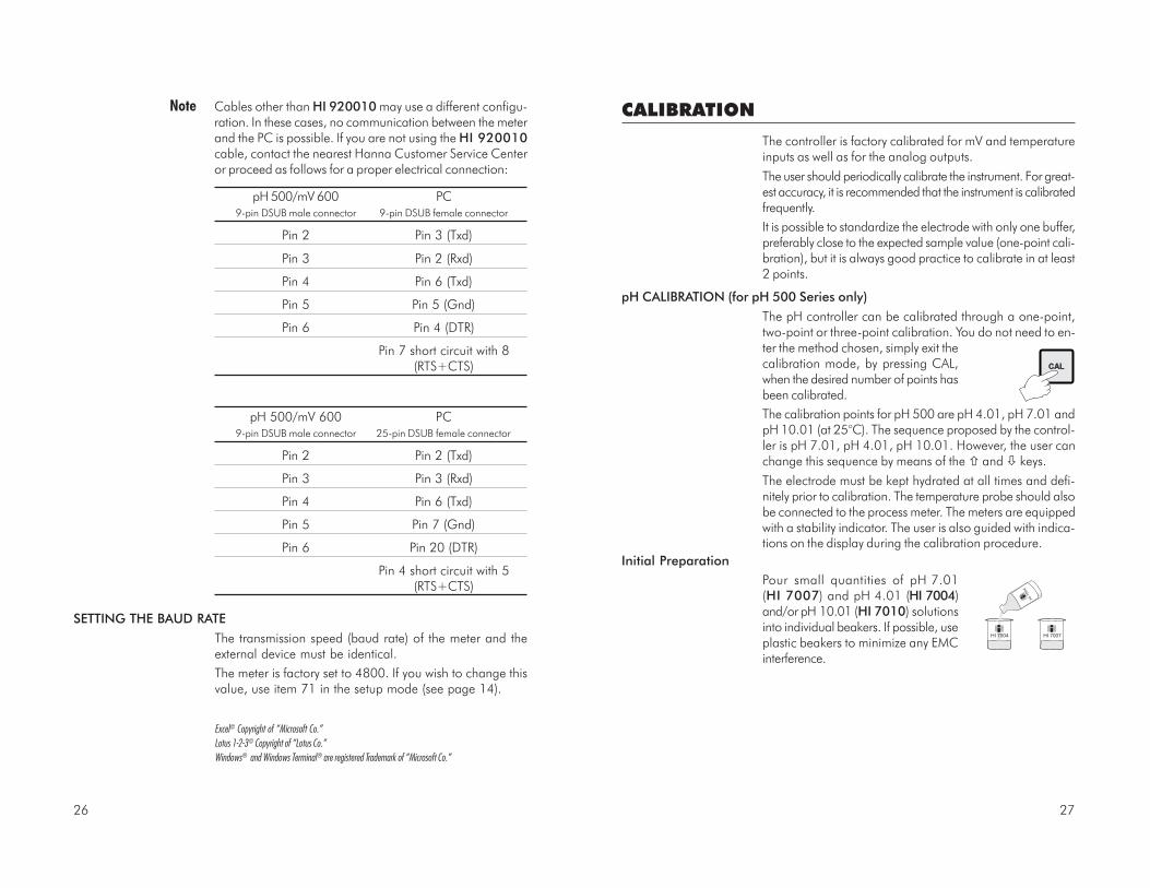
CALIBRATION
The controller is factory calibrated for mV and temperatureinputs as well as for the analog outputs.
The user should periodically calibrate the instrument. For great-est accuracy, it is recommended that the instrument is calibratedfrequently.
It is possible to standardize the electrode with only one buffer,preferably close to the expected sample value (one-point cali-bration), but it is always good practice to calibrate in at least2 points.
pH CALIBRATION (for pH 500 Series only)
The pH controller can be calibrated through a one-point,two-point or three-point calibration. You do not need to en-ter the method chosen, simply exit thecalibration mode, by pressing CAL,when the desired number of points hasbeen calibrated.
The calibration points for pH 500 are pH 4.01, pH 7.01 andpH 10.01 (at 25°C). The sequence proposed by the control-ler is pH 7.01, pH 4.01, pH 10.01. However, the user canchange this sequence by means of the and keys.
The electrode must be kept hydrated at all times and defi-nitely prior to calibration. The temperature probe should alsobe connected to the process meter. The meters are equippedwith a stability indicator. The user is also guided with indica-tions on the display during the calibration procedure.
Initial Preparation
Pour small quantities of pH 7.01(HI 7007) and pH 4.01 (HI 7004)and/or pH 10.01 (HI 7010) solutionsinto individual beakers. If possible, useplastic beakers to minimize any EMCinterference.
HI 7007
HI 7
004
HI 7004
Excel© Copyright of “Microsoft Co.”
Lotus 1-2-3© Copyright of “Lotus Co.”
Windows® and Windows Terminal® are registered Trademark of “Microsoft Co.”
Note Cables other than HI 920010 may use a different configu-ration. In these cases, no communication between the meterand the PC is possible. If you are not using the HI 920010cable, contact the nearest Hanna Customer Service Centeror proceed as follows for a proper electrical connection:
pH 500/mV 600 PC9-pin DSUB male connector 9-pin DSUB female connector
Pin 2 Pin 3 (Txd)
Pin 3 Pin 2 (Rxd)
Pin 4 Pin 6 (Txd)
Pin 5 Pin 5 (Gnd)
Pin 6 Pin 4 (DTR)
Pin 7 short circuit with 8(RTS+CTS)
pH 500/mV 600 PC9-pin DSUB male connector 25-pin DSUB female connector
Pin 2 Pin 2 (Txd)
Pin 3 Pin 3 (Rxd)
Pin 4 Pin 6 (Txd)
Pin 5 Pin 7 (Gnd)
Pin 6 Pin 20 (DTR)
Pin 4 short circuit with 5(RTS+CTS)
SETTING THE BAUD RATE
The transmission speed (baud rate) of the meter and theexternal device must be identical.
The meter is factory set to 4800. If you wish to change thisvalue, use item 71 in the setup mode (see page 14).

2928
• Remove the protective cap from thepH electrode and immerse it into theselected buffer solution (e.g. pH 7.01)with the Potential Matching Pin andtemperature probe, then stir gently.
Note The electrode should be submerged ap-proximately 4 cm (1½") in the solution.The temperature probe should be locatedas close as possible to the pH electrode.
Note When it is not possible to immerse the Potential Matching Pintogether with the pH electrode in the solution, disable thedifferential input by connecting the Connection for PotentialMatching Pin (#9 at page 7) with the Connection for Elec-trode Reference (#8 at page 7) with a jumper wire.
• Only when the reading is stable the
probe indicator " " will stop flashing(after about 30 seconds) and the"CFM" indicator will start blinking.
• Press CFM to confirm the calibration; if the reading is close tothe selected buffer (±1.5 pH), the meter stores the readingand the secondary LCD will display the expected second buffervalue. Offset and slope calculation is made at the end bypressing CAL to exit.
If the reading is not close to the selectedbuffer, "WRONG BUF " will blink.
• If CAL is pressed, the calibration pro-cess ends by memorizing a new offsetvalue. The new offset value is storedand a default value of 59.16 mV perpH unit at 25°C is assigned as thenew slope value.
For best accuracy however, it is recommended that a two-point calibration is performed.
HI 7007
CALIBRATION
HI 7007
RINSE
For accurate calibration, use two beakers for each buffersolution, the first one for rinsing the electrode, the secondone for calibration. By doing this, contamination betweenthe buffers is minimized.
To obtain accurate readings, use pH 7.01 and pH 4.01 ifyou measure acidic samples, or pH 7.01 and pH 10.01 foralkaline measurements or perform a 3-point calibration forthe entire range.
One Point Calibration (Offset)
• To perform the pH calibration enterthe calibration mode, by pressingCAL and entering the password.
• After the correct password is entered,the control actions stop and the pri-mary LCD will display the pH valueusing the current offset and slope,
with the "CAL" and " BUF
1
" indicators lit
and the probe indicator " " blink-ing. The value displayed on thesecondary LCD is the buffer valueat the actual temperature.
Note The actual pH value varies with temperature, thus the cali-bration value displayed on the secondary LCD will vary aroundpH 4.01, 7.01 and 10.01 with temperature changes: for ex-ample at 25 oC the display shows 4.01 - 7.01 - 10.01, at 20oC it shows 4.00 - 7.03 - 10.06 (see page 47 for other val-ues).
• pH 7.01 is the default value forthe 1st calibration buffer. If a dif-ferent value is needed, select iton the secondary display bypressing or .
Note If the wrong password is entered the system reverts back andrestarts displaying the pH value.
3130
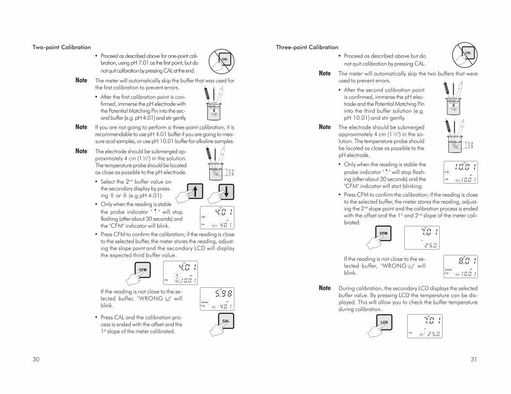
Three-point Calibration
• Proceed as described above but do
not quit calibration by pressing CAL.
Note The meter will automatically skip the two buffers that wereused to prevent errors.
• After the second calibration pointis confirmed, immerse the pH elec-trode and the Potential Matching Pininto the third buffer solution (e.g.pH 10.01) and stir gently.
Note The electrode should be submergedapproximately 4 cm (1½") in the so-lution. The temperature probe shouldbe located as close as possible to thepH electrode.
• Only when the reading is stable the
probe indicator " " will stop flash-ing (after about 30 seconds) and the"CFM" indicator will start blinking.
• Press CFM to confirm the calibration; if the reading is closeto the selected buffer, the meter stores the reading, adjust-ing the 2nd slope point and the calibration process is endedwith the offset and the 1st and 2nd slope of the meter cali-brated.
If the reading is not close to the se-lected buffer, "WRONG BUF " willblink.
Note During calibration, the secondary LCD displays the selectedbuffer value. By pressing LCD the temperature can be dis-played. This will allow you to check the buffer temperatureduring calibration.
Two-point Calibration
• Proceed as described above for one-point cali-bration, using pH 7.01 as the first point, but do
not quit calibration by pressing CAL at the end.
Note The meter will automatically skip the buffer that was used forthe first calibration to prevent errors.
• After the first calibration point is con-firmed, immerse the pH electrode withthe Potential Matching Pin into the sec-ond buffer (e.g. pH 4.01) and stir gently
Note If you are not going to perform a three-point calibration, it isrecommendable to use pH 4.01 buffer if you are going to mea-sure acid samples, or use pH 10.01 buffer for alkaline samples.
Note The electrode should be submerged ap-proximately 4 cm (1½") in the solution.The temperature probe should be locatedas close as possible to the pH electrode.
• Select the 2nd buffer value onthe secondary display by press-ing or (e.g.pH 4.01).
• Only when the reading is stable
the probe indicator " " will stopflashing (after about 30 seconds) andthe "CFM" indicator will blink.
• Press CFM to confirm the calibration; if the reading is closeto the selected buffer, the meter stores the reading, adjust-ing the slope point and the secondary LCD will displaythe expected third buffer value.
If the reading is not close to the se-lected buffer, "WRONG BUF " willblink.
• Press CAL and the calibration pro-cess is ended with the offset and the1st slope of the meter calibrated.

3332
mV INPUT CALIBRATION
The pH/mV controller is factory calibrated for the mV andtemperature inputs. However, the user may also perform amV calibration.
• Short the Connection for Potential Matching Pin (#9 atpage7) and the Connection for the Electrode Reference(#8 at page 7) with a jumper wire.
• Attach a HI 931001 (pH 500) or HI 8427 (mV 600) simu-lator to the BNC socket.
• Press and hold first CFM and thenCAL to enter the mV Input Cali-bration mode.
• Execute the password procedure.
• With pH 500, the meter will ask for the calibration proce-dure code number. The following table lists the possiblevalues of the input code and calibration points:
INPUT CODE POINTS CAL.VALUES INPUT RANGE
mV 0 2 0 & 350 or 0 & 1900* ±2000,
Temp. 1 2 0 & 25 or 0 & 50 -9.9 to 120.0 �C
* One of the points must be 0. 1900 mV calibration point is available
on mV 600 models only.
When calibrating the mV of mV 600 models, enter thecalibration mode by pressing CAL and confirming the pass-word (as for pH calibration of pH 500). No code selectionis required.
• Use or to select code 0 for mV calibration and pressCFM to enter.
• CAL will blink on the LCD until themeter confirms a steady reading.
CALIBRATION WITH MANUAL TEMPERATURE COMPENSATION
• Enter the calibration procedure and press LCD to displaythe temperature on the secondary LCD.
• Unplug any temperature probe that maybe attached to the meter. The "°C" sym-bol will flash.
• Note the temperature of the buffer solutions with aChecktempC or an accurate thermometer with a resolutionof 0.1°C.
• Use or to manually adjust the display reading to thevalue of the reference thermometer (e.g. 20°C).
• Follow the calibration procedure above (see page 27).
Note To toggle between the pH buffer and thetemperature press LCD.
When a one-point calibration is carried out only the pH off-set is computed and stored, while the pH slope is fixedaccording to the theoretical values.
With a two-point calibration, offset and slope are computedto fit the two calibration points. With a three-point calibra-tion the offset and first slope values refers to pH 4.01 and7.01 buffers, while the second slope refers to pH 7.01 and10.01 buffers.
Note If the process meter has never been cali-brated or an EEPROM reset has occurred,the meter continues to perform measure-ment. However, user is informed of a pH calibrationrequirement by a blinking “CAL” (see “Startup” section).
The device must be calibrated within the temperature rangeof 0-95°C. Outside this range, the buffer pH values are notreliable.

3534
• Use a Checktemp or a calibrated thermometer with a reso-lution of 0.1° as a reference thermometer.
• Immerse the temperature probe inthe beaker with ice and water as nearto the Checktemp as possible.
• Press and hold first CFM and thenCAL to enter the temperature cali-bration mode.
• Execute the password procedure.
• With pH 500, the meter will ask for the calibration proce-dure code number. Use or to select code 1 for thetemperature calibration and press CFM to enter.
• CAL will blink on the LCD until themeter confirms a steady reading.
• When the reading has stabilized ata point near the first calibrationpoint, CAL will stop blinking and anintermittent CFM will prompt the userto confirm the first calibration.
• If the reading stabilizes at a readingsignificantly variant from the firstsetpoint, an intermittent WRONGwill prompt the user to check thebeaker or baths.
• After pressing CFM the unit will switch to the second cali-bration point.
• Select 25 or 50°C by pressing or .
0 °C(32 °F)
°C
• When the reading has stabilized ata point near the first calibrationpoint, CAL will stop blinking and anintermittent CFM icon will prompt theuser to confirm the first calibration.
• If the display stabilizes at a valuesignificantly different from the firstsetpoint, an intermittent WRONGicon will prompt the user to checkand adjust the simulator and startagain.
• After pressing CFM the unit will switch to the second cali-bration point at 350 mV.
• With mV 600 it is possible to select 1900 mV by pressing or . After that, proceed as described above.
Note A measure is considered stable when it varies little within asequence of acquisitions. The number of acquisitions is fixedso that the waiting time for blinking “CFM” is about 20 sec-onds.
Calibration procedure may be interrupted bypressing CAL. If the calibration procedure is in-terrupted this way, or if the controller is switchedoff before the last step, no calibration data isstored to EEPROM.
TEMPERATURE CALIBRATION
The pH/mV controller is factory calibrated for the mV andtemperature inputs. However, the user may also perform atemperature calibration.
• Prepare a beaker containing iceand water at 0°C/32°F and an-other one with hot water at25°C/77°F or 50°C/122°F. 0 °C
(32 °F)
°C
50 ºC(122 ºF)
°C

3736
• Press CFM to confirm the selected parameter that will stopblinking on the primary display. The secondary display showsthe HI 931002 or multimeter input value as lower limit ofthe interval.
• Use the or to make theHI 931002 or multimeter out-put correspond with themeter’s value shown on thesecondary display (e.g. 4).
• Wait for approximately 30 seconds (until the reading ofthe calibrator is stable).
• Press CFM to enter. The meter will switch to the secondcalibration point. Repeat the above procedure.
• After the desired readings are obtained, press CFM andthe meter will skip back to normal operating mode.
Note When adjusting values using the or it is important toallow for sufficient response time (up to 30 seconds)
The table below lists the values of output codes along withthe calibration point values (which are the analog outputminimum and the analog output maximum) as indicatedon the display.
The secondary display indicates the current calibration pointvalue, while primary display indicates the current calibra-tion type.
• Immerse the temperature probe inthe second beaker as near to theChecktemp as possible and repeatthe above procedure.
Calibration procedure may be interrupted by pressing CALagain at any time. If the calibration procedure is stoppedthis way, or if the controller is switched off before the laststep, no calibration data is stored in non-volatile memory(EEPROM).
ANALOG OUTPUT CALIBRATION
In the meters where the analog output is available, thisfeature is factory calibrated through software. The user mayalso perform these calibration procedures.
IMPORTANT It is recommended to perform the output calibration at leastonce a year. Calibration should only be performed after10 minutes from power up.
• With a multimeter or an HI 931002connect the common port to theground output and the second portto the current output or voltage out-put (depending on which parameteris being calibrated).
• Press and hold in sequence CFM first, then and thenCAL to enter the Analog Output Calibration mode.
• Execute the password procedure.
• The primary display will show the current selected param-eter blinking. Use the to select the code (0-5 see chartbelow) for the desired parameter displayed on the second-ary display (e.g. 4-20 mA).
50 °C(122 °F)
°C

3938
LAST CALIBRATION DATA
The meter stores the following information about last calibration inthe EEPROM:
• Date
• Time
• Offset in mV (for pH 500 only)
• Up to two slopes (for pH 500 only)
• Up to three buffers
While displaying this data, the pH controller remains in con-trol mode.
The procedure below indicates the flow for a three-point cali-bration. The sequence will vary if fewer calibration points areused (e.g. for a one-point calibration the following data willbe displayed: date, time, offset, first slope, buffer 1 value).For the mV 600, last calibration data includes date and timeof calibration and the values of the 2 calibration points. Dis-playing of these items follows the above sequence.
• To begin the cycle press CAL DATA. The last calibrationdate will appear on the main LCD display as DD.MMformat, while the secondary display will show the year.
If the meter has never calibrated or an EEPROM reset has
occurred, no calibration data is shown when CAL DATA ispressed. The “no CAL” message will blink for a few sec-onds, then the meter skips back to normal mode.
• Pressing will cycle through the fol-lowing steps in reverse order, i.e. lastbuffer.
OUTPUT CALIBRATION CALIBRATION CALIBRATIONTYPE CODE POINT 1 POINT 2
0-1 mA 0 0 mA 1 mA
0-20 mA 1 0 mA 20 mA
4-20 mA 2 4 mA 20 mA
0-5 VDC 3 0 VDC 5 VDC
1-5 VDC 4 1 VDC 5 VDC
0-10 VDC 5 0 VDC 10 VDC

4140
• Press or again to view the second memorized bufferat the time of last calibration. The secondary display willshow "BUF2" to indicate second buffer.
• Press or again to view the third memorized buffer atthe time of last calibration. The secondary display willshow "BUF3" to indicate third buffer.
• Press or again to return to the first CAL DATA display(date) at the time of last calibration.
Note In any moment, by pressing LCD or CAL DATA the meter willreturn to the regular operating display.
• Press or to view the time of last calibration. The sec-ondary display will show "HOU" to indicate hours.
• Press or again to view the offset in mV at the time oflast calibration. The secondary display will show "OFF"to indicate offset.
• Press or again to view the first slope in mV at the timeof last calibration. The secondary display will show "SL1" toindicate first slope.
• Press or again to view the second slope in mV at thetime of last calibration. The secondary display will show"SL2" to indicate second slope.
• Press or again to view the first memorized buffer atthe time of last calibration. The secondary display willshow "BUF1" to indicate first buffer.

4342
FAULT CONDITIONS AND SELFTEST PROCEDURES
The fault conditions below may be detected by the software:
• EEPROM data error;
• I2C internal bus failure;
• code dead loop.
EEPROM data error can be detected through EEPROM testprocedure at startup or when explicitly requested using setupmenu.
When an EEPROM error is detected, user is given the optionto perform a reset of EEPROM. Thus the reset can be per-formed whenever needed. It may be useful to provide a meansto reset EEPROM directly (without a previous EEPROM errordetection). This is done by pressing CFM first and then SETUP,
and CAL DATA simultaneously.
Note When an EEPROM reset has been per-formed calibration data are reset todefault. An intermittent CAL will blinkon the display to advise the user ofthis status.
A I2C failure is detected when the I2C transmission is notacknowledged or a bus fault occurs for more than a certainnumber of attempts (this can be due, for example, to dam-age sustained by one of the ICs connected to I2C bus).
If so, the controller stops any tasks and displays a perpetualsliding message “Serial bus error” (i.e. this is a fatal error).
STARTUP
At startup the firmware release code scrolls through the LCD;it is possible to escape from code scrolling pressing any key.
During the automatic startup the Real Time Clock (RTC) ischecked to see if a reset occurred since last software ini-tialization. In this case, the RTC is initialized with the defaultdate and time 01/01/1997 - 00:00. An EEPROM resetdoes not affect the RTC settings.
The EEPROM is also checked to see if it is new. If this is thecase, the default values are copied from ROM and thenthe device enters normal mode. Otherwise an EEPROMchecksum test is performed (the same is performed duringEEPROM selftest procedure).
If checksum is correct, normal mode is entered, otherwiseuser is asked whether the EEPROM should be reset.
If EEPROM reset is requested, default values from ROMare stored into EEPROM as would happen with a newEEPROM.
Note that EEPROM data is composed of setup data andcalibration data. As for the setup data, the calibration data isassigned default values when an EEPROM reset occurs. Anun-calibrated meter can perform mea-surement, though user is informed thatpH calibration (pH models) or mV cali-bration (mV models) is needed bymeans a blinking “CAL” icon.
When the last calibration data is re-quired, the “no CAL” message isdisplayed if no calibration procedurewas performed.
Unlike pH and mV calibration, user has no information oncalibration need for other magnitudes, other than the aware-ness that EEPROM was reset.
After an EEPROM reset, all calibrations (input and output)have to be performed in order to obtain correct measure-ments.
4544
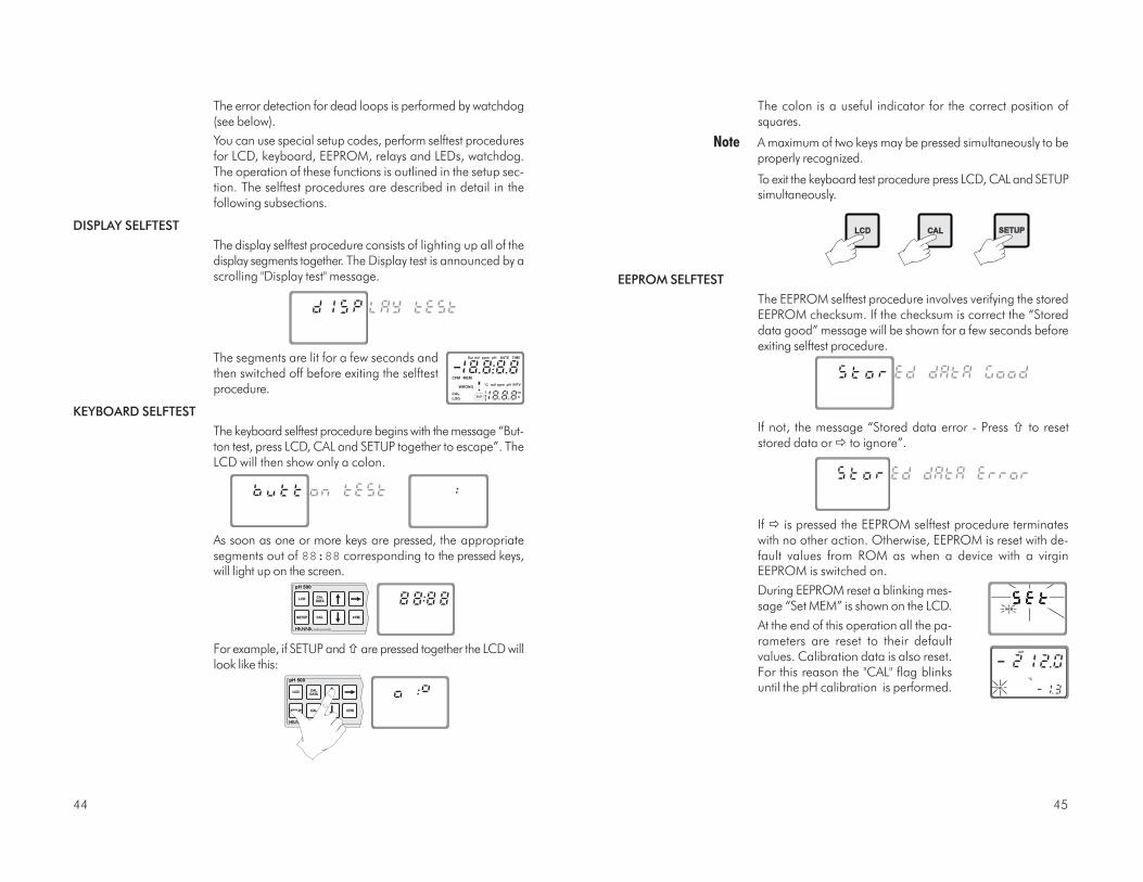
The colon is a useful indicator for the correct position ofsquares.
Note A maximum of two keys may be pressed simultaneously to beproperly recognized.
To exit the keyboard test procedure press LCD, CAL and SETUPsimultaneously.
EEPROM SELFTEST
The EEPROM selftest procedure involves verifying the storedEEPROM checksum. If the checksum is correct the “Storeddata good” message will be shown for a few seconds beforeexiting selftest procedure.
If not, the message “Stored data error - Press to resetstored data or to ignore”.
If is pressed the EEPROM selftest procedure terminateswith no other action. Otherwise, EEPROM is reset with de-fault values from ROM as when a device with a virginEEPROM is switched on.
During EEPROM reset a blinking mes-sage “Set MEM” is shown on the LCD.
At the end of this operation all the pa-rameters are reset to their defaultvalues. Calibration data is also reset.For this reason the "CAL" flag blinksuntil the pH calibration is performed.
The error detection for dead loops is performed by watchdog(see below).
You can use special setup codes, perform selftest proceduresfor LCD, keyboard, EEPROM, relays and LEDs, watchdog.The operation of these functions is outlined in the setup sec-tion. The selftest procedures are described in detail in thefollowing subsections.
DISPLAY SELFTEST
The display selftest procedure consists of lighting up all of thedisplay segments together. The Display test is announced by ascrolling "Display test" message.
The segments are lit for a few seconds andthen switched off before exiting the selftestprocedure.
KEYBOARD SELFTEST
The keyboard selftest procedure begins with the message “But-ton test, press LCD, CAL and SETUP together to escape”. TheLCD will then show only a colon.
As soon as one or more keys are pressed, the appropriatesegments out of 88:88 corresponding to the pressed keys,will light up on the screen.
For example, if SETUP and are pressed together the LCD willlook like this:

4746
pH VALUES AT VARIOUS TEMPERATURES
Temperature has a significant effect on pH. The calibrationbuffer solutions are effected by temperature changes to a lesserdegree than normal solutions.
For manual temperature calibration please refer to the fol-lowing chart:
TEMP pH VALUES°C °F 4.01 7.01 10.01
0 32 4.01 7.13 10.32
5 41 4.00 7.10 10.24
10 50 4.00 7.07 10.18
15 59 4.00 7.04 10.12
20 68 4.00 7.03 10.06
25 77 4.01 7.01 10.01
30 86 4.02 7.00 9.96
35 95 4.03 6.99 9.92
40 104 4.04 6.98 9.88
45 113 4.05 6.98 9.85
50 122 4.06 6.98 9.82
55 131 4.07 6.98 9.79
60 140 4.09 6.98 9.77
65 149 4.11 6.99 9.76
70 158 4.12 6.99 9.75
For instance, if the buffer temperature is 25°C, the displayshould show pH 4.01, 7.01 or 10.01 at pH 4, 7 or 10buffers, respectively.
At 20°C, the display should show pH 4.00, 7.03 or 10.06.The meter reading at 50°C will then be 4.06, 6.98 or 9.82.
RELAYS AND LEDS
Relays and LEDs selftests are executed as follows:
First all of the relays and LEDs are switched off, then they areswitched on one at a time for a few seconds and cyclically.User can interrupt the otherwise endless cycle, as indicatedby the scrolling message, by pressing a key.
Note Relays and LEDs test has to be carried out with the relaycontacts disconnected from external plant devices.
WATCHDOG
When a dead loop condition is detected a reset is automati-cally invoked.
The effectiveness of watchdog capability can be tested throughone of the special setup items. This test consists of executinga dummy dead loop that causes watchdog reset signal to begenerated.

4948
If the bulb and/or junction are dry, soak the electrode inHI 70300 Storage Solution for at least one hour.
For refillable electrodes**: If the refill solution (electrolyte) is more than 2½ cm (1")below the fill hole, add HI 7082 3.5M KCl Electrolyte So-lution for double junction or HI 7071 3.5M KCl+AgClElectrolyte Solution for single junction electrodes.
For AmpHel® electrodes: If the electrode does not respond to pH changes, the bat-tery is run down and the electrode should be replaced.
TEST MEASUREMENT
Rinse the electrode tip with distilled water.
Immerse the tip (bottom 4 cm / 1½") in the sample and stirgently for approx. 30 seconds.
For a faster response and to avoid cross contamination ofthe samples, rinse the electrode tip with the solution to betested, before taking your measurements.
STORAGE
To minimize clogging and assure a quick response time,the glass bulb and the junction should be kept moist andnot allowed to dry out. This can be achieved by installingthe electrode in such a way that it is constantly in a wellfilled with the sample (stream or tank).
When not in use, replace the solution in the protective capwith a few drops of HI 70300 Storage Solution or, in itsabsence, HI 7007 pH 7.01 Buffer Solution.
Follow the Preparation Procedure above before taking mea-surements.
Note NEVER STORE THE ELECTRODE IN DISTILLED OR DEION-IZED WATER.
PERIODIC MAINTENANCE
Inspect the electrode and the cable. The cable used for theconnection to the controller must be intact and there mustbe no points of broken insulation on the cable or cracks onthe electrode stem or bulb.
Connectors must be perfectly clean and dry. If any scratchesor cracks are present, replace the electrode. Rinse off any saltdeposits with water.
ELECTRODE CONDITIONING AND MAINTENANCE
* Only available with refillable electrodes. For industrial applications, gel-filled electrodes are preferabledue to lesser maintenance requirements.
PREPARATION
Remove the protective cap.
DO NOT BE ALARMED IF ANY SALT DEPOSITS AREPRESENT.
This is normal with electrodes and they will disappear whenrinsed with water.
During transport tiny bubbles of air may have formed in-side the glass bulb. The electrode cannot function properlyunder these conditions. These bubbles can be removed by"shaking down" the electrode as you would do with a glassthermometer.

5150
• No Slope:
- Check the electrode for cracks in glass stem or bulb(replace the electrode if cracks are found).
- Make sure cable and connections are not damagednor lying in a pool of water or solution.
• Slow Response/Excessive Drift: Soak the tip in HannaSolution HI 7061 for 30 minutes, rinse thoroughly indistilled water and then follow the Cleaning Procedureabove.
• For ORP Electrodes: polish the metal tip with a lightlyabrasive paper (paying attention not to scratch the sur-face) and wash thoroughly with water.
Note With industrial applications, it is always recommended tokeep at least one spare electrode handy. When anomaliesare not resolved with a simple maintenance, change theelectrode (and recalibrate the controller) to see if the prob-lem is alleviated.
For refillable electrodes**: Refill the electrode with fresh electrolyte (HI 7071 for singlejunction or HI 7082 for double junction electrodes). Allowthe electrode to stand upright for 1 hour. Follow the Stor-age Procedure above.
CLEANING PROCEDURE
General Soak in Hanna HI 7061 General CleaningSolution for approximately ½ hour.
Removal of films, dirt or deposits on the membrane/junction:
Protein Soak in Hanna HI 7073 Protein CleaningSolution for 15 minutes.
Inorganic Soak in Hanna HI 7074 Inorganic CleaningSolution for 15 minutes.
Oil/grease Rinse with Hanna HI 7077 Oil and FatCleaning Solution.
IMPORTANT After performing any of the cleaning procedures rinse theelectrode thoroughly with distilled water, drain and refillthe reference chamber with fresh electrolyte, (not neces-sary for gel-filled electrodes) and soak the electrode inHI 70300 Storage Solution for at least 1 hour before re-installing it.
TROUBLESHOOTING
Evaluate your electrode performance based on the following.
• Noise (Readings fluctuate up and down) could be due to:
- Clogged/Dirty Junction: Refer to the Cleaning Proce-dure above.
- Loss of shielding due to low electrolyte level (in refill-able electrodes only): refill with HI 7071 for singlejunction or HI 7082 for double junction electrodes.
• Dry Membrane/Junction: Soak in Storage SolutionHI 70300 for at least 1 hour. Check to make sure theinstallation is such as to create a well for the electrodebulb to constantly remain moist.
• Drifting: Soak the electrode tip in warm Hanna SolutionHI 7082 for one hour and rinse tip with distilled water(refill with fresh HI 7071 for single junction electrodesand HI 7082 for double junction electrodes if neces-sary).
• Low Slope: Refer to the cleaning procedure above.

5352
pH mV pH mV pH mV pH mV pH mV
0 990 1 920 2 860 3 800 4 740
5 680 6 640 7 580 8 520 9 460
10 400 11 340 12 280 13 220 14 160
Reducing pretreatment: immerse the electrode for a few min-utes in HI 7091.
Oxidizing pretreatment: immerse the electrode for a few min-utes in HI 7092.
If the pretreatment is not performed, the electrode will takesignificantly longer to respond.
As with pH electrodes, gel-filled redox electrodes are moresuitable for industrial applications due to lesser mainte-nance requirements. However, if working with refillableelectrodes, the electrolyte level should not fall more than2½ cm (1") below the fill hole and topped up if necessary.Use HI 7071 Refill Solution for single junction and HI 7082for double junction electrodes.
In the event that measurements are performed with solu-tions containing sulfides or proteins, the cleaning of thediaphragm of the reference electrode must be performedmore often to maintain the proper functioning of the ORPelectrode. Therefore, immerse it into HI 7020 and mea-sure the response; the obtained value should be within200 and 275 mV.
After this functional test, it is suggested to wash the elec-trode thoroughly with water and proceed to the oxidizingor reducing pretreatment before taking measurements.
When not in use, the electrode tip should be kept moistand far from any type of mechanical stress which mightcause damage. This can be achieved by installing the elec-trode in such a way that it is constantly in a well filled withthe sample (stream or tank). The protective cap can alsobe filled with HI 70300 Storage Solution if the electrode isnot being used at all.
Note With industrial applications, it is always recommended tokeep at least one spare electrode handy. When anomaliesare not resolved with a simple maintenance, change the elec-trode to see if the problem is alleviated.
TAKING REDOX MEASUREMENTS
Redox measurements allow the quantification of the oxidizingor reducing power of a solution, and are commonly expressedin mV.
Oxidation may be defined as the process during which amolecule (or an ion) loses electrons and reduction as theprocess by which electrons are gained.
Oxidation is always coupled together with reduction sothat as one element gets oxidized, the other is automati-cally reduced, therefore the term oxidation-reduction isfrequently used.
Redox potentials are measured by an electrode capable ofabsorbing or releasing electrons without causing a chemicalreaction with the elements with which it comes into contact.
The electrodes most usually available for this purpose havegold or platinum surfaces; gold possesses a higher resis-tance than platinum in conditions of strong oxidation suchas cyanide, while platinum is preferred for the measure-ments of oxidizing solutions containing halides and forgeneral use.
When a platinum electrode is immersed in an oxidizingsolution a monomolecular layer of oxygen is developedon its surface. This layer does not prevent the electrodefrom functioning, but it increases the response time. Theopposite effect is obtained when the platinum surface ab-sorbs hydrogen in the presence of reducing mediums. Thisphenomenon is rough on the electrode.
To make correct redox measurements the following condi-tions must prevail:
– The surface of the electrode must be cleaned and smooth.
– The surface of the electrode must undergo a pretreat-ment in order to respond quickly.
Because the Pt/PtO system depends on the pH, the pre-treatment of the electrode may be determined by the pHand the redox potential values of the solution to be mea-sured.
As a general rule, if the ORP mV reading corresponding tothe pH value of the solution is higher than the values in thetable below, an oxidizing pretreatment is necessary; other-wise a reducing pretreatment is necessary:

5554
RECOMMENDED pH ELECTRODES (All electrodes gel-filled and with ceramicjunction unless otherwise indicated).HI 1090T Screw connector, external PG13.5 thread, double junction,
glass-body, polymer filled
HI 1210T Screw connector, external PG13.5 thread, double junction,
HI 1211T Ultem®-body; cloth junction (HI 1210T); Teflon® junction,polymer-filled (HI 1211T)
HI 2910B/5 BNC connector, 5 m (16.5') cable, double junction, Ultem®-
HI 2911B/5 body with built-in amplifier and external thread; cloth junc-tion (HI 2910B/5); Teflon® junction, polymer-filled (HI 2911B/5)
HI 1090B/5 BNC connector, 5 m (16.5') cable, double junction, glass-body, polymer-filled
HI 1210B/5 BNC connector, 5 m (16.5') cable, double junction, Ultem®-body, Teflon® junction, polymer-filled
ACCESSORIES
pH CALIBRATION SOLUTIONS
HI 7004M pH 4.01 Buffer Solution, 230 mL
HI 7004L pH 4.01 Buffer Solution, 460 mL
HI 7004/L pH 4.01 Buffer Solution, 1 L
HI 7007M pH 7.01 Buffer Solution, 230 mL
HI 7007L pH 7.01 Buffer Solution, 460 mL
HI 7007/L pH 7.01 Buffer Solution, 1 L
HI 7010M pH 10.01 Buffer Solution, 230 mL
HI 7010L pH 10.01 Buffer Solution, 460 mL
HI 7010/L pH 10.01 Buffer Solution, 1 L
ORP SOLUTIONS
HI 7020M 200-275mV Buffer Solution, 230 mL
HI 7020L 200-275mV Buffer Solution, 460 mL
HI 7091M Pretreatment Reducing Solution, 230 mL
HI 7091L Pretreatment Reducing Solution, 460 mL
HI 7092M Pretreatment Oxidizing Solution, 230 mL
HI 7092L Pretreatment Oxidizing Solution, 460 mL
ELECTRODE STORAGE SOLUTIONS
HI 70300M Storage Solution, 230 mL
HI 70300L Storage Solution, 460 mL
ELECTRODE CLEANING SOLUTIONS
HI 7061M General Cleaning Sol., 230 mL
HI 7061L General Cleaning Sol., 460 mL
HI 7073M Protein Cleaning Sol., 230 mL
HI 7073L Protein Cleaning Sol., 460 mL
HI 7074M Inorganic Cleaning Sol., 230 mL
HI 7074L Inorganic Cleaning Sol., 460 mL
HI 7077M Oil & Fat Cleaning Sol., 230 mL
HI 7077L Oil & Fat Cleaning Sol., 460 mL
REFILL ELECTROLYTE SOLUTIONS
HI 7071 3.5M KCl+AgCl Electrolyte, 4x50 mL, for single junctionelectrodes
HI 7072 1M KNO3 Electrolyte, 4x50 mL
HI 7082 3.5M KCl Electrolyte, 4x50 mL, for double junction elec-trodes

5756
HI 3210B/5 BNC connector, 5 m (16.5') cable, double junction, Pt,Ultem®-body, Teflon® junction, polymer-filled
GOLD ORP ELECTRODES
HI 4932B/5 BNC connector, 5 m (16.5') cable, double junction, Au,Ultem®-body with built-in amplifier and external thread
ELECTRODES FOR HIGH PRESSURE APPLICATIONS
pH ELECTRODES
½‘’ thread, double Teflon® junction, polymer filled, max operating pressure of 6 bar (87psi)
Part CodePart CodePart CodePart CodePart Code Matching Pin Matching Pin Matching Pin Matching Pin Matching Pin AmplifierAmplifierAmplifierAmplifierAmplifier ConnectorConnectorConnectorConnectorConnector CableCableCableCableCable
HI 1002/3 NO NO BNC 3 m (10’)
HI 1002/5 NO NO BNC 5 m (16.5’)
HI 1003/3 YES NO BNC* 3 m (10’)
HI 1003/5 YES NO BNC* 5 m (16.5’)
HI 1004/5 YES YES spade lugs* 5 m (16.5’)
* In addition to the electrode connector, there is also a spade lug connection for the
matching pin
PLATINUM ORP ELECTRODES
HI 3090T Screw connector, external PG13.5 thread, double junction,Pt, glass-body, polymer filled
HI 3210T Screw connector, external PG13.5 thread, double junction,Pt, Ultem®-body, cloth junction
HI 3211T Screw connector, external PG13.5 thread, double junction,Pt, Ultem®-body, Teflon® junction, polymer-filled
HI 2930B/5 BNC connector, 5 m (16.5') cable, double junction, Pt,Ultem®-body with built-in amplifier and external thread, clothjunction
HI 2931B/5 BNC connector, 5 m (16.5') cable, double junction, Pt,Ultem®-body with built-in amplifier and external thread,Teflon® junction, polymer-filled
HI 3090B/5 BNC connector, 5 m (16.5') cable, double junction, Pt, glass-body, polymer-filled

5958
ORP ELECTRODES
½‘’ thread, double Teflon® junction, polymer filled, max operating pressure of 6 bar (87psi)
PLATINUM ELECTRODES
Part CodePart CodePart CodePart CodePart Code Matching PinMatching PinMatching PinMatching PinMatching Pin AmplifierAmplifierAmplifierAmplifierAmplifier ConnectorConnectorConnectorConnectorConnector CableCableCableCableCable
HI 2002/3 NO NO BNC 3 m (10’)
HI 2002/5 NO NO BNC 5 m (16.5’)
HI 2003/3 YES NO BNC* 3 m (10’)
HI 2003/5 YES NO BNC* 5 m (16.5’)
HI 2004/5 YES YES spade lugs* 5 m (16.5’)
GOLD ELECTRODES
Part CodePart CodePart CodePart CodePart Code Matching PinMatching PinMatching PinMatching PinMatching Pin AmplifierAmplifierAmplifierAmplifierAmplifier ConnectorConnectorConnectorConnectorConnector CableCableCableCableCable
HI 2012/3 NO NO BNC 3 m (10’)
HI 2012/5 NO NO BNC 5 m (16.5’)
HI 2013/3 YES NO BNC* 3 m (10’)
HI 2013/5 YES NO BNC* 5 m (16.5’)
HI 2005/5 YES YES spade lugs* 5 m (16.5’)
* In addition to the electrode connector, there is also a spade lug connection for the
matching pin
Ultem® is a registered Trademark of "General Electrics Company"
OTHER ACCESSORIES
BL PUMPS Dosing Pumps with Flow Rate from 1.5 to 20 LPH
ChecktempC Stick Thermometer (range -50.0 to 150.0°C)
ChecktempF Stick Thermometer (range -58.0 to 302°F)
HI 6050 & HI 6051 Submersible Electrode Holders
HI 6054 & HI 6057 Electrode Holders for In-Line Applications
HI 778P Screened Coaxial Cable and Screw Connectors
HI 7871 & HI 7873 Level Controllers
HI 8427 pH / ORP Electrode Simulator
HI 8614 pH Transmitter
HI 8614L pH Transmitter with LCD
HI 8615 ORP Transmitter
HI 8615L ORP Transmitter with LCD
HI 920010 9 to 25-pin Connection RS 232 Cable
HI 920010-9 9 to 9-pin Connection RS 232 Cable
HI 92500 Windows® Compatible Application Software
HI 931001 pH / ORP Electrode Simulator with LCD Display
HI 931002 4-20 mA Simulator

6160
OTHER PRODUCTS FROM HANNA
• CALIBRATION AND MAINTENANCE SOLUTIONS
• CHEMICAL TEST KITS
• CHLORINE METERS
• CONDUCTIVITY/TDS METERS
• DISSOLVED OXYGEN METERS
• HYGROMETERS
• ION SPECIFIC METERS (Colorimeters)
• MAGNETIC STIRRERS
• Na/NaCl METERS
• pH/ORP/Na ELECTRODES
• PROBES (DO, µS/cm, RH, T, TDS)
• PUMPS
• REAGENTS
• SOFTWARE
• THERMOMETERS
• TITRATORS
• TRANSMITTERS
• TURBIDITY METERS
• Wide Range of Accessories
Most Hanna meters are available in the following formats:
• BENCH-TOP METERS
• POCKET-SIZED METERS
• PORTABLE METERS
• PRINTING/LOGGING METERS
• PROCESS METERS (Panel and Wall-mounted)
• WATERPROOF METERS
• METERS FOR FOOD INDUSTRY
For additional information, contact your dealer or the near-est Hanna Customer Service Center.You can also e-mail us at [email protected].
WARRANTY
All Hanna Instruments meters are guaranteed for twoyears against defects in workmanship and materials whenused for their intended purpose and maintained accord-ing to instructions. The electrodes and the probes areguaranteed for a period of six months. This warranty islimited to repair or replacement free of charge.
Damage due to accident, misuse, tampering or lack ofprescribed maintenance are not covered.
If service is required, contact the dealer from whom youpurchased the instrument. If under warranty, report themodel number, date of purchase, serial number and thenature of the failure. If the repair is not covered by thewarranty, you will be notified of the charges incurred. If theinstrument is to be returned to Hanna Instruments, first ob-tain a Returned Goods Authorization number from theCustomer Service department and then send it with ship-ping costs prepaid. When shipping any instrument, makesure it is properly packaged for complete protection.
To validate your warranty, fill out and return the enclosedwarranty card within 14 days from the date of purchase.
Hanna Instruments reserves the right to modify the design,construction and appearance of its products without ad-vance notice.

6362
CE DECLARATION OF CONFORMITY
Recommendations for Users
Before using these products, make sure that they are entirely suitable forthe environment in which they are used.
Operation of these instruments in residential areas could cause unaccept-able interferences to radio and TV equipment.
To maintain the EMC performance of equipment, the recommendedcables noted in the user's manual must be used.
Any variation introduced by the user to the supplied equipment maydegrade the instruments' EMC performance.
To avoid electrical shock, do not use these instruments when voltage at themeasurement surface exceed 24VAC or 60VDC.
To avoid damage or burns, do not perform any measurement in microwaveovens.
Unplug the instruments from power supply before the replacement of thefuse.
External cables to be connected to the rear panel should be terminated withcable lugs.
HANNA LITERATURE
Hanna publishes a wide range of catalogs and handbooksfor an equally wide range of applications. The reference lit-erature currently covers areas such as:
• Water Treatment
• Process
• Swimming Pools
• Agriculture
• Food
• Laboratory
• Thermometry
and many others. New reference material is constantly beingadded to the library.
For these and others catalogs, handbooks and leaflets, con-tact your dealer or the Hanna Customer Service Center nearestto you. To find the Hanna Office in your vicinity, check ourhome page at www.hannainst.com

h t t p : / / w w w . h a n n a i n s t . c o m
MAN
PH500R5
12/0
0


![Generation of hydrogen from the Solar Photolysis of Water ... · Potential [mV] I sc = 17.73 mA/cm 2 V oc = 846 mV FF = 0.745 Efficiency = 11.18 80 60 40 20 0 IPCE (%) 400 500 600](https://static.fdocuments.us/doc/165x107/5f9987c736d7854d5e474c66/generation-of-hydrogen-from-the-solar-photolysis-of-water-potential-mv-i-sc.jpg)