ph 197i kompakt de - globalw.com · ba75675defs01 01/2007 pH 1970i Bedienungsanleitung Operating...
60
ba75675defs01 01/2007 pH 1970i Bedienungsanleitung Operating manual Mode d’emploi Instrucciones de operación Portables pH/mV-Meßgerät Seite 3 Portable pH/mV Measuring Instrument Page 17 Appareil portable de mesure du pH/mV Page 31 Medidor portátil para pH/mV Página 45 pH 6 246 99 ° C TP REL1 RUN / ENTER RUN / ENTER AUTO READ AUTO READ CAL CAL STO M RCL RCL ON / OFF ON / OFF pH 1970i pH 1970i
Transcript of ph 197i kompakt de - globalw.com · ba75675defs01 01/2007 pH 1970i Bedienungsanleitung Operating...

pH 1970i
BedienungsanleitungOperating manual
Mode d’emploiInstrucciones de operación
Portables pH/mV-Meßgerät Seite 3
Portable pH/mV Measuring Instrument Page 17
Appareil portable de mesure du pH/mV Page 31
Medidor portátil para pH/mV Página 45
pH
62 4 6
99°C TP
REL1
RUN / ENTERRUN / ENTER
AUTO READAUTO READ
CALCAL
STO
M
RCLRCL
ON / OFFON / OFF
pH 1970ipH 1970i
ba75675defs01 01/2007

pH 1970i
Hinweise zu dieserBedienungs-
anleitung
Diese Bedienungsanleitung enthält in kompakter Form
die Beschreibung aller Grundfunktionen,
alle Hinweise für den sicheren Betrieb und
alle technischen Daten.
Eine ausführlichere Beschreibung mit Hinweisen für besondere Anwendun-gen ist als pdf-Dokument im Internet unter http://www.WTW.com erhältlich.
Note to thisoperating manual
This operating manual contains a description of
all basic functions,
all instructions for a safe operation, and
all technical data in a compact form.
A more detailed description with notes for special applications is available as a pdf document via internet under http://www.WTW.com.
Remarque à cemode d’emploi
Ce mode d'emploi contient sous forme compacte
la description de toutes les fonctions de base et
toutes les informations assurant un fonctionnement sûr, ainsi que
tous les données techniques.
Une description plus étendue contenant les informations sur des emplois spéciaux peut être obtenue sous forme pdf dans l'internet sous http://www.WTW.com.
Observacióna estas
instrucciones
Este manual de instrucciones incluye la descripción en forma resumida de
todas las funciones básicas,
todas las observaciones que le garantizan el
funcionamiento normal y seguro, asimismo todo las especificaciones y datos técnicos.
En el internet, bajo http://www.WTW.com encuentra Ud. una descripción más detallada, en formato pdf, para aplicaciones especiales.
Copyright © Weilheim 2007, WTW GmbH
2 ba75675defs01 01/2007

pH 1970i Sicherheit / Inhaltsverzeichnis
3ba75675d01 01/2007
pH 1970i - Inhaltsverzeichnis
Sicherheit . . . . . . . . . . . . . . . . . . . . . . . . . . . . . . . . . . . . . . . . . . . . . . . . . . 3
Display und Buchsenfeld. . . . . . . . . . . . . . . . . . . . . . . . . . . . . . . . . . . . . . . 4
Akku / Netzbetrieb. . . . . . . . . . . . . . . . . . . . . . . . . . . . . . . . . . . . . . . . . . . . 5
Meßgerät einschalten . . . . . . . . . . . . . . . . . . . . . . . . . . . . . . . . . . . . . . . . . 6
Messen . . . . . . . . . . . . . . . . . . . . . . . . . . . . . . . . . . . . . . . . . . . . . . . . . . . . 6
Kalibrieren . . . . . . . . . . . . . . . . . . . . . . . . . . . . . . . . . . . . . . . . . . . . . . . . . . 7
Speichern . . . . . . . . . . . . . . . . . . . . . . . . . . . . . . . . . . . . . . . . . . . . . . . . . 11
Datenspeicher ausgeben . . . . . . . . . . . . . . . . . . . . . . . . . . . . . . . . . . . . . 11
Datenspeicher löschen . . . . . . . . . . . . . . . . . . . . . . . . . . . . . . . . . . . . . . . 11
Daten übertragen . . . . . . . . . . . . . . . . . . . . . . . . . . . . . . . . . . . . . . . . . . . 11
Schreiber (Analogausgang) . . . . . . . . . . . . . . . . . . . . . . . . . . . . . . . . . . . 12
Konfigurieren. . . . . . . . . . . . . . . . . . . . . . . . . . . . . . . . . . . . . . . . . . . . . . . 12
Rücksetzen (Reset) auf Grundeinstellungen . . . . . . . . . . . . . . . . . . . . . . 13
Entsorgung . . . . . . . . . . . . . . . . . . . . . . . . . . . . . . . . . . . . . . . . . . . . . . . . 14
Technische Daten . . . . . . . . . . . . . . . . . . . . . . . . . . . . . . . . . . . . . . . . . . . 15
SicherheitSicherheits-
hinweiseIn den einzelnen Kapiteln dieser Bedienungsanleitung weisen Sicherheits-hinweise wie der Folgende auf Gefahren hin:
Achtungkennzeichnet Hinweise, die genau beachtet werden müssen, um mögliche leichte Verletzungen oder Schäden am Gerät oder der Umwelt zu vermeiden.

Display und Buchsenfeld pH 1970i
Display und Buchsenfeld
Display
Buchsenfeld
ARngnLF Oxi
Tref25 Tref20 REL2REL1
Salcm1/
m cmS/% mg/l
SSal
O
Lin
K/%
pHmV/pH
88 8 8 8
881°C
Time
Year
LoBat Cal TEC AR RCL
Ident
Auto Store
TPNo.Day.Month
Baud
Statusanzeige
Meßwertanzeige
Funktions- und Temperaturanzeige
Sensorsymbol
Sensor / Gerät Buchse / Position
pH-Tiefenarmatur Die Eingänge 1 und 2 dürfen nicht gleichzeitig belegt sein.
1
pH-Elektrode oder pH-Einstabmeßkette 2
pH-Einstabmeßkette mit Temperaturmeßfühler 2 und 4
Referenzelektrode 3
Temperaturmeßfühler, extern 3 und 4
Drucker, Schreiber oder PC (serielle Schnittstelle RS232) 5
Steckernetzgerät 6
Wasserdichtes Ventil zum Innendruckausgleich 7
1
34
2
5
6
7
4 ba75675d01 01/2007

pH 1970i Akku / Netzbetrieb
AchtungSchließen Sie an das Meßgerät nur Meßketten an, die keine unzulässigen Spannungen oder Ströme (> SELV und > Stromkreis mit Strombegrenzung) einspeisen können. Nahezu alle Meßketten - insbesondere WTW-Meßketten - erfüllen diese Bedingungen.
Akku / NetzbetriebDas Steckernetzgerät versorgt das Meßgerät mit Kleinspannung (12 V DC). Gleichzeitig wird der Akku geladen (ca. 16 Stunden). Die Anzeige LoBat erscheint, wenn der Akku weitgehend entladen ist.
AchtungDie Netzspannung am Einsatzort muß innerhalb des Eingangs-Spannungsbereichs des Original-Steckernetzgeräts liegen (siehe TECHNISCHE DATEN).
AchtungVerwenden Sie nur Original-Steckernetzgeräte (siehe TECHNISCHE DATEN).
2
1
3
Stecker (1) in die Buchse (2) des Meßgeräts stecken.
Original WTW-Steckernetzgerät (3) an eine leicht zugängliche Steckdose anschließen
5ba75675d01 01/2007

Meßgerät einschalten pH 1970i
Meßgerät einschalten
MessenÜberblick über die Meßmodi:
Spezialfunktionen:
AutoRead(Driftkontrolle)
Die Funktion AutoRead prüft die Stabilität des Meßsignals (außer bei der Messung bei Redoxspannung). AutoRead mit <AR> aktivieren. Zum Starten der AutoRead-Messung <RUN/ENTER> drücken. Während der AutoRead-Messung blinkt die Anzeige AR, bis ein stabiler Meßwert vorliegt. Ein Abbruch mit Übernahme des aktuellen Meßwerts ist jederzeit mit <RUN/ENTER> möglich.
Temperaturmes-sung bei pH-Mes-
sungen
Sie können pH-Meßketten mit und ohne Temperaturmeßfühler verwenden. Das Meßgerät erkennt den Temperaturmeßfühler automatisch und schaltet in den richtigen Modus der Temperaturmessung (Anzeige TP).Manuelle Temperatureingabe: Temperaturwert mit <▲> <▼> einstellen.
Taste <ON/OFF> drücken.Im Display erscheint kurz der Displaytest.Das Meßgerät schaltet danach automatisch in den Meßmodus. Das Display zeigt den zugehörigen Meßwert an.
pH-WertRedox-
spannungmV<M>
6 ba75675d01 01/2007

pH 1970i Kalibrieren
KalibrierenAutoCal TEC ist als vollautomatische Ein-, Zwei-, oder Dreipunktkalibrierung speziell auf
die WTW-Technischen Pufferlösungen abgestimmt. Die Pufferlösungen werden vom Meßgerät automatisch erkannt. Je nach Geräteeinstellung zeigt das Gerät den zugehörigen Puffersollwert oder die aktuelle Meßkettenspannung in mV an.
Gültige Puffer (Werte bei 25 °C): 2,00 / 4,01 / 7,00 / 10,01
HinweisDie Kalibrierung bei pH 10,01 ist für die WTW-Technische Pufferlösung TEP 10 Trace bzw. TPL 10 Trace optimiert. Andere Pufferlösungen können zu einer fehlerhaften Kalibrierung führen. Die richtigen Pufferlösungen finden Sie im WTW-Katalog oder im Internet.
AutoCal DIN wie AutoCal TEC, jedoch abgestimmt auf Pufferlösungen nach DIN 19266.
Gültige Puffer (Werte bei 25 °C): 1,679 / 4,006 / 6,865 / 9,180
ConCal ist die konventionelle Zweipunktkalibrierung mit zwei Pufferlösungen (pH 7,0 ± 0,5 und eine beliebige weitere Pufferlösung) bzw. eine Einpunktkalibrierung mit einer beliebigen Pufferlösung als Schnellmethode.
Kalibrier-bewertung
Nach dem Kalibrieren bewertet das Meßgerät automatisch die Kalibrierung. Asymmetrie und Steilheit werden dabei getrennt bewertet. Die jeweils schlechtere Bewertung erscheint im Display.
HinweisWenn ein Drucker an die Schnittstelle angeschlossen ist, wird nach einer gültigen Kalibrierung automatisch ein Kalibrierprotokoll gedruckt.
Anzeige E3Unzulässige Kalibrierung
Asymmetrie[mV]
-15 ... +15 -20 ... +20 -25 ... +25 -30 ... +30 < -30 bzw. > 30
Steilheit[mV/pH]
-60,5 ... -58 -58 ... -57 -61 ... -60,5 bzw. -57 ... -56
-62 ... -61 bzw. -56 ... -50
< -62 bzw. > -50
7ba75675d01 01/2007

Kalibrieren pH 1970i
Ablauf AutoCal TEC / AutoCal DIN:
Das folgende Beispiel zeigt die AutoCal TEC Kalibrierung. Bei der AutoCal DIN Kalibrierung wird im Display Cd... statt Ct... angezeigt. Ansonsten sind beide Abläufe identisch.
Die Auswahl AutoCal TEC Kalibrierung (Anzeige Ct1) oder AutoCal DIN Kalibrierung (Anzeige Cd1) erfolgt mit der Taste <CAL>.
pH-Meßkette an das Meßgerät anschließen.
Taste <CAL> so oft drücken, bis die Anzeige Ct1 und die Funktionsanzeige Auto Cal TEC erscheint. Das Sensorsymbol zeigt die Bewertung der letzten Kalibrierung an (bzw. kein Sensorsymbol im Auslieferzustand oder nach einem Reset der Meßparameter).
pH-Meßkette in die erste Pufferlösung tauchen.
bei Messung ohne Temperaturmeßfühler: Temperatur der ersten Pufferlösung mit <▲> <▼> eingeben.
<RUN/ENTER> drücken. Die AutoRead-Messung beginnt. Im Display erscheint die Meßkettenspannung (mV) oder der Puffersollwert (siehe KONFIGURIEREN). Wenn der Meßwert stabil ist, erscheint Ct2.
HinweisAn dieser Stelle kann die AutoCal TEC-Kalibrierung mit <M> abgebrochen werden. Dies entspricht einer Einpunktkalibrierung. Dabei verwendet das Gerät die Nernst-Steilheit (-59,16 mV/pH bei 25 °C) und ermittelt die Asymmetrie der Meßkette.
Zum Fortsetzen der Zweipunktkalibrierung pH-Meßkette in die zweite Pufferlösung tauchen.
bei Messung ohne Temperaturmeßfühler: Temperatur der zweiten Pufferlösung mit <▲> <▼> eingeben.
<RUN/ENTER> drücken. Die AutoRead-Messung beginnt. Im Display erscheint die Meßkettenspannung (mV) oder der Puffersollwert.
Wenn der Meßwert stabil ist, zeigt das Gerät den Wert der Steilheit und die Bewertung der Zweipunktkalibrierung an.
<RUN/ENTER> drücken. Das Gerät zeigt den Wert der Asymmetrie an.
HinweisAn dieser Stelle kann die AutoCal TEC-Kalibrierung mit <M> abgebrochen werden. Dies entspricht einer Zweipunktkalibrierung.
Store
AR
1
LoBat nLF Lin Oxi
Tref25 Tref20
ARng
8Time
Year Ident
No.Day.Month
Baud Salcm1/K/%
RCL
REL2
pH/mV
m cmS/% mg/l
SalO
SpH
C2 4 8
T 1°C TP
REL1
Cal TEC
Auto
Store
AR
1
LoBat nLF Lin Oxi
Tref25 Tref20
ARng
8Time
Year Ident
No.Day.Month
Baud Salcm1/K/%
RCL
REL2
pH/mV
m cmS/% mg/l
SalO
SpH
C2 4 8
T 2°C TP
REL1
Cal TEC
Auto
- m cmS/% mg/l
SalO
SpH
594pHmV/
1pH
cmS/mg/l
SalO
SpH
2mV
Store
AR
1
LoBat nLF Lin Oxi
Tref25 Tref20
ARng
8Time
Year Ident
No.Day.Month
Baud Salcm1/K/%
RCL
REL2
pH/mV
m cmS/% mg/l
SalO
SpH
C2 4 8
T 3°C TP
REL1
Cal TEC
Auto
8 ba75675d01 01/2007
pH 1970i Kalibrieren
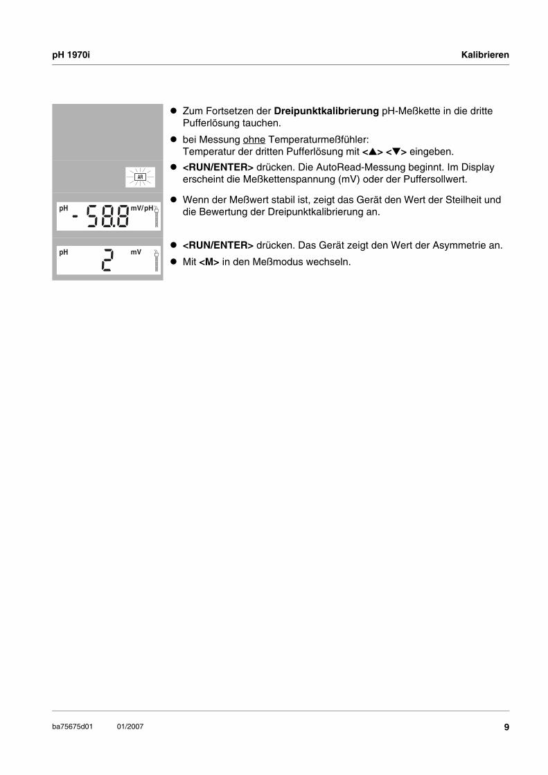
Zum Fortsetzen der Dreipunktkalibrierung pH-Meßkette in die dritte Pufferlösung tauchen.
bei Messung ohne Temperaturmeßfühler: Temperatur der dritten Pufferlösung mit <▲> <▼> eingeben.
<RUN/ENTER> drücken. Die AutoRead-Messung beginnt. Im Display erscheint die Meßkettenspannung (mV) oder der Puffersollwert.
Wenn der Meßwert stabil ist, zeigt das Gerät den Wert der Steilheit und die Bewertung der Dreipunktkalibrierung an.
<RUN/ENTER> drücken. Das Gerät zeigt den Wert der Asymmetrie an.
Mit <M> in den Meßmodus wechseln.
- m cmS/% mg/l
SalO
SpH
588pHmV/
1pH
cmS/mg/l
SalO
SpH
2mV
9ba75675d01 01/2007

Kalibrieren pH 1970i
Ablauf ConCal:
pH-Meßkette an das Meßgerät anschließen.
Taste <CAL> so oft drücken, bis die Anzeige ASY und die Funktionsanzeige Cal erscheint. Das Sensorsymbol zeigt die Bewertung der letzten Kalibrierung an (bzw. kein Sensorsymbol im Auslieferzustand oder nach einem Reset der Meßparameter).
pH-Meßkette in die erste Pufferlösung tauchen (pH 7,0 ± 0,5 bei Zweipunktkalibrierung).
bei Messung ohne Temperaturmeßfühler: Temperatur der ersten Pufferlösung bei gedrückter Taste <RUN/ENTER> mit <▲> <▼> eingeben.
Taste <RUN/ENTER> drücken.Im Display erscheint der pH-Meßwert.
Meßwert mit <▲> <▼> auf den nominalen pH-Wert der Pufferlösung (bei der aktuellen Temperatur) einstellen.
Wenn der Meßwert stabil ist, Taste <RUN/ENTER> drücken. Es erscheint der Wert der Asymmetrie.
Taste <RUN/ENTER> drücken. Es erscheint SLO.
HinweisAn dieser Stelle kann die ConCal-Kalibrierung mit <M> abgebrochen werden. Dies entspricht einer Einpunktkalibrierung. Dabei verwendet das Gerät die Nernst-Steilheit (-59,16 mV/pH bei 25 °C) und ermittelt die Asymmetrie der Meßkette.
Zum Fortsetzen der Zweipunktkalibrierung pH-Meßkette in die zweite Pufferlösung tauchen.
bei Messung ohne Temperaturmeßfühler: Temperatur der zweiten Pufferlösung bei gedrückter Taste <RUN/ENTER> mit <▲> <▼> eingeben.
<RUN/ENTER> drücken.
Meßwert mit <▲> <▼> auf den nominalen pH-Wert der Pufferlösung (bei der aktuellen Temperatur) einstellen.
Wenn der Meßwert stabil ist, Taste <RUN/ENTER> drücken. Das Gerät zeigt den Wert der Steilheit und die Kalibrierbewertung an.
<RUN/ENTER> drücken. Das Gerät zeigt den Wert der Asymmetrie an.
Mit <M> in den Meßmodus wechseln.
TEC
Auto Store
AR
1
LoBat nLF Lin Oxi
Tref25 Tref20
ARng
8Time
Year Ident
No.Day.Month
Baud Salcm1/K/%
RCL
REL2
pH/mV
m cmS/% mg/l
SalO
SpH
A2 4 8
S Y°C TP
REL1
Cal
7
TEC
Auto Store
ARLoBat nLF Lin Oxi
Tref25 Tref20
ARng
8Time
Year Ident
No.Day.Month
Baud Salcm1/K/%
RCL
REL2
pH/mV
m cmS/% mg/l
SalO
SpH
72 4 8
02°C TP
REL1
Cal
4
TEC
Auto Store
ARLoBat nLF Lin Oxi
Tref25 Tref20
ARng
8Time
Year Ident
No.Day.Month
Baud Salcm1/K/%
RCL
REL2
pH/mV
m cmS/% mg/l
SalO
SpH
S2 4 8
L O°C TP
REL1
Cal
7
TEC
Auto Store
ARLoBat nLF Lin Oxi
Tref25 Tref20
ARng
8Time
Year Ident
No.Day.Month
Baud Salcm1/K/%
RCL
REL2
pH/mV
m cmS/% mg/l
SalO
SpH
$2 4 8
5 8°C TP
REL1
Cal
- m cmS/% mg/l
SalO
SpH
594pHmV/
C T1pH/
m cmS/% mg/l
SalO
SpH
3mV
10 ba75675d01 01/2007
pH 1970i Speichern
SpeichernDas Meßgerät verfügt über einen internen Datenspeicher. Darin können bis zu 800 Datensätze abgespeichert werden.
Daten manuellspeichern
Im Meßmodus Taste <STO> drücken (Anzeige No. mit der Nummer des nächsten freien Speicherplatzes). Anschließend <RUN/ENTER> drücken und Identnummer mit <▲> <▼> eingeben. Speichern mit <RUN/ENTER> abschließen. Das Gerät wechselt in den Meßmodus.
Daten automatischSpeichern Int 1
Das Speicherintervall (Int 1) bestimmt den zeitlichen Abstand zwischen automatischen Speichervorgängen. Zum Einstelllen des Speicherintervalls <STO> bei gedrückter Taste <RUN/ENTER> drücken (Anzeige Int 1) und Intervall mit <▲> <▼> einstellen. Anschließend <RUN/ENTER> drücken. Die Anzahl der noch verfügbaren freien Speicherplätze wird angezeigt. Erneut <RUN/ENTER> drücken und Identnummer mit <▲> <▼> eingeben. Mit <RUN/ENTER> in den zuletzt aktiven Meßmodus wechseln. Das automatische Speichern ist eingeschaltet (Anzeige Auto Store).
Datenspeicher ausgebenMit der Taste <RCL> können Sie den Datenspeicher ausgeben. Durch mehrmaliges Drücken der Taste <RCL> gelangen Sie zu folgenden Funktionen:
Ausgabe mit <RUN/ENTER> starten.
Datenspeicher löschenMeßgerät ausschalten. Taste <STO> drücken und festhalten. Taste <ON/OFF> drücken. Mit <RUN/ENTER> den Löschvorgang bestätigen oder durch Drücken einer beliebigen anderen Taste den Löschvorgang abbrechen.
Daten übertragenDaten manuell
übertragenIm Meßmodus Taste <RUN/ENTER> drücken. Damit lösen Sie jederzeit manuell eine Datenübertragung des aktuellen Meßwertes zur seriellen Schnittstelle aus - unabhängig von den eingestellten Intervallen.
StO dISP gespeicherte Daten auf Display ausgeben
StO SEr gespeicherte Daten auf serielle Schnittstelle ausgeben
CAL dISP Kalibrierdaten auf Display ausgeben
CAL SEr Kalibrierdaten auf serielle Schnittstelle ausgeben
11ba75675d01 01/2007

Schreiber (Analogausgang) pH 1970i
Daten automatischübertragen Int 2
Das Intervall zur Datenübertragung (Int 2) bestimmt den zeitlichen Abstand zwischen automatischen Datenübertragungen. Nach Ablauf des eingestellten Intervalls wird der aktuelle Datensatz an die Schnittstelle übertragen. Zum Einstelllen des Übertragungsintervalls <RCL> bei gedrückter Taste <RUN/ENTER> drücken (Anzeige Int 2). Anschließend Intervall mit <▲> <▼> einstellen.
Schreiber (Analogausgang)Über den Analogausgang können Sie die Daten an einen Schreiber übertragen. Verbinden Sie den Analogausgang über das Schnittstellenkabel AK323/S mit dem Schreiber. Die Datenausgabe schaltet automatisch auf Schreiberausgabe.
HinweisDie Ausgabe an den Analogausgang entspricht dem am Display angezeigten Wert (pH 7.00 wird als 700 mV ausgegeben).
KonfigurierenHinweisSie können das Konfigurationsmenü jederzeit mit <M> verlassen. Die bereits geänderten Parameter sind gespeichert.
Ablauf Konfigurieren (Werkseinstellungen sind fett gekennzeichnet):
Meßgerät ausschalten.
Bei gedrückter Taste <M> Taste <ON/OFF> drücken.
Gewünschte Baudrate mit <▲> <▼> einstellen. Auswahl: 1200, 2400, 4800, 9600 Baud.
Anschließend Taste <RUN/ENTER> drücken.
Gewünschte Anzeige während der pH-Kalibrierung mit <▲> <▼> einstellen.Auswahl: Puffersollwert (/pH) oder aktuelle Meßkettenspannung (mV).
Anschließend Taste <RUN/ENTER> drücken.
Gewünschtes Kalibrierintervall mit <▲> <▼> einstellen.Auswahl: 1 ... 7 ... 999 d.
Anschließend Taste <RUN/ENTER> drücken.
Datum und Uhrzeit Schritt für Schritt mit <▲> <▼> einstellen. Dazwischen jeweils Taste <RUN/ENTER> drücken.
Nach dem letzten Druck auf die Taste <RUN/ENTER> wechselt das Gerät in den zuletzt aktiven Meßmodus.
SaTP°CYear Ident
No.Day.Month
Time cm1/K/%8 0 04
Baud
Sal
mg/lO
TP°C
S
Year Ident
No.Day.Month
SalCTime Baud cm1/
K/%
mV
m cmS/%C
I S P
ALd
pH pH/
TP
Sal1
O
cm1/
4 TP°C
cmS/Sal
%
S%
mmg/l
Year Ident
No.Day.Month
SalBaud
K/
pH/mV
7
3n td
ITime
pH
Day.Month 0 9 0 4
12 ba75675d01 01/2007

pH 1970i Rücksetzen (Reset) auf Grundeinstellungen
Rücksetzen (Reset) auf GrundeinstellungenSie können die Meßparameter und die Konfiguration getrennt voneinander auf den Lieferzustand rücksetzen (initialisieren).
Meßparameter Die folgenden Meßparameter lassen sich auf den Auslieferzustand rücksetzen:
Konfigurations-parameter
Die folgenden Konfigurationsparameter (InI) lassen sich auf den Auslieferzustand rücksetzen:
Ablauf Rücksetzen:
Meßmodus pH
Steilheit -59,16 mV/pH
Asymmetrie 0 mV
Manuelle Temperatureinstellung 25 °C
Baudrate 4800
Anzeige während pH-Kalibrierung Puffersollwert
Intervall 1(automatisches Speichern) OFF
Intervall 2(für Datenübertragung) OFF
Bei gedrückter Taste <RUN/ENTER> Taste <CAL> drücken.
Zum Rücksetzen der Meßparameter mit <▲> <▼> YES wählen und mit <RUN/ENTER> bestätigen, oder
mit Taste <RUN/ENTER> ohne Rücksetzen weiter zu den Konfigurationsparametern (InI).
Nach den Konfigurationsparametern InI wechselt das Gerät in den zuletzt aktiven Meßmodus.
O
Day.Month 0 9Time
Icm1/
TP°C
cmS/Sal
%
S%
mmg/l
Year Ident
No.
SalBaud
K/
pH/mV
n o
iinpH
13ba75675d01 01/2007

Entsorgung pH 1970i
EntsorgungEntfernen Sie den Akku aus dem Gerät und führen Sie ihn gemäß den lokalen gesetzlichen Bestimmungen einer Entsorgungseinrichtung zu.
Akku ausbauen
Befestigungselemente (1) abschrauben.
Durch kräftigen Druck gegen das Buchsenfeld das Gerät aus dem Gehäuse lösen. Anschließend den Akku (2) herausnehmen und das Akkukabel durchtrennen.
Ni-Cd Cd
1
1
2
14 ba75675d01 01/2007

pH 1970i Technische Daten
Technische Daten
Abmessungen ca. 90 x 200 x 190 mm
Gewicht ca. 1,5 kg (ohne Steckernetzgerät)
Mechan. Aufbau Schutzart: IP 67
Elektr. Sicherheit Schutzklasse: III
Prüfzeichen CE
Umgebungs-bedingungen
Lagerung - 25 °C ... + 65 °C
Betrieb -10 °C ... + 55 °C
Klimaklasse 2
Energie-versorgung
Akku Nickel-Cadmium(NiCd)-Akku
Laufzeit ca. 600 Stunden mit einer Akkuladung
Steckernetzgerät(Ladegerät)
Für alle Steckernetzgeräte gilt:Anschluß max. Überspannungskategorie II
Steckernetzgerät mit Euro-, US-, UK- und Austr. Stecker:FRIWO FW7555M/09, 15.1432Friwo Part. No. 1883259Input: 100 ... 240 V ~ / 50 ... 60 Hz / 400 mAOutput: 9 V = / 1,5 A
SerielleSchnittstelle
(Kabel AK 340/Boder AK 325/S)
Typ RS232, Datenausgabe
Baudrate einstellbar: 1200, 2400, 4800, 9600 Baud
Datenbits 8
Stoppbits 2
Parität keine (None)
Handshake RTS/CTS+Xon/Xoff
Kabellänge max. 15m
15ba75675d01 01/2007

Technische Daten pH 1970i
Meßbereiche, Auflösungen, Genauigkeiten
* bei Messungen im Bereich von ± 2 pH um einen Kalibrierpunkt
Analogausgang(Kabel AK 323/S)
Automatische Umschaltung bei Anschluß des Schreiberkabels AK 323/S.
Ausgangssignal pH -200 ... +1999 mV für Bereichspanne -2,00 ... +19,99
Ausgangssignal mV -1999 ... +1999 mV für Bereichspanne -1999 ... +1999 mV
Genauigkeit ± 0,5 % vom Anzeigewert
Innenwiderstand < 5 Ohm (Strombegrenzung auf max. 0,2 mA Ausgangsstrom)
AngewendeteRichtlinien und
Normen
EMV EG-Richtlinie 89/336/EWGEN 61326-1:1998EN 61000-3-2 A14:2000EN 61000-3-3:1995FCC Class A
Gerätesicherheit EG-Richtlinie 73/23/EWGEN 61010-1 A2:1995
Klimaklasse VDI/VDE 3540
IP-Schutzart EN 60529:1991
Größe Meßbereich Auflösung Genauigkeit (± 1 Digit)
pH - 2,00 ... + 19,99 0,01 ± 0,01 *
U [mV] - 199,9 ... + 199,9- 1999 ... + 1999
0,11
± 0,5± 1
T [°C] - 5,0 ... + 105,0 0,1 ± 0,1
ManuelleTemperatur-
eingabe
Größe Bereich Schrittweite
Tmanuell [°C] - 20 ... + 130 1
16 ba75675d01 01/2007

pH 1970i Safety / List of contents
17
pH 1970i - List of contents
ba75675e01 01/2007
Safety . . . . . . . . . . . . . . . . . . . . . . . . . . . . . . . . . . . . . . . . . . . . . . . . . . . . 17
Display and socket field . . . . . . . . . . . . . . . . . . . . . . . . . . . . . . . . . . . . . . 18
Battery / mains operation . . . . . . . . . . . . . . . . . . . . . . . . . . . . . . . . . . . . . 19
Switching on the measuring instrument . . . . . . . . . . . . . . . . . . . . . . . . . . 20
Measuring . . . . . . . . . . . . . . . . . . . . . . . . . . . . . . . . . . . . . . . . . . . . . . . . . 20
Calibration . . . . . . . . . . . . . . . . . . . . . . . . . . . . . . . . . . . . . . . . . . . . . . . . . 21
Saving data . . . . . . . . . . . . . . . . . . . . . . . . . . . . . . . . . . . . . . . . . . . . . . . . 25
Outputting the data memory . . . . . . . . . . . . . . . . . . . . . . . . . . . . . . . . . . . 25
Erasing the data storage . . . . . . . . . . . . . . . . . . . . . . . . . . . . . . . . . . . . . . 25
Transmitting data . . . . . . . . . . . . . . . . . . . . . . . . . . . . . . . . . . . . . . . . . . . 25
Recorder (Analog output) . . . . . . . . . . . . . . . . . . . . . . . . . . . . . . . . . . . . . 26
Configuring . . . . . . . . . . . . . . . . . . . . . . . . . . . . . . . . . . . . . . . . . . . . . . . . 26
Resetting to default settings . . . . . . . . . . . . . . . . . . . . . . . . . . . . . . . . . . . 27
Disposal . . . . . . . . . . . . . . . . . . . . . . . . . . . . . . . . . . . . . . . . . . . . . . . . . . 28
Technical data. . . . . . . . . . . . . . . . . . . . . . . . . . . . . . . . . . . . . . . . . . . . . . 29
SafetySafety
instructionsThe individual chapters of this operating manual use safety instructions such as that shown below to indicate various hazards or dangers:
Warningindicates instructions that must be followed precisely in order to avoid the possibility of slight injuries or damage to the instrument or the environment.

Display and socket field pH 1970i
18 ba75675e01 01/2007
Display and socket field
Display
Socket field
ARngnLF Oxi
Tref25 Tref20 REL2REL1
Salcm1/
m cmS/% mg/l
SSal
O
Lin
K/%
pHmV/pH
88 8 8 8
881°C
Time
Year
LoBat Cal TEC AR RCL
Ident
Auto Store
TPNo.Day.Month
Baud
Status display indicator
Measured value display
Function and Temperature display
Sensor symbol
Sensor / Instrument Socket / Position
pH depth armature The sockets, 1 and 2 must not be assigned at the same time.
1
pH electrode or pH combination electrode 2
pH combination electrode with temperature sensor 2 and 4
Reference electrode 3
Temperature sensor, external 3 and 4
Printer, recorder or PC (serial interface, RS232) 5
Plug-in power supply unit 6
Watertight valve for internal pressure equalization 7
1
34
2
5
6
7
pH 1970i Battery / mains operation
19ba75675e01 01/2007
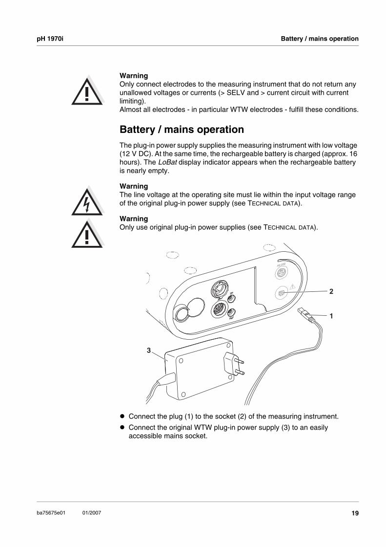
WarningOnly connect electrodes to the measuring instrument that do not return any unallowed voltages or currents (> SELV and > current circuit with current limiting). Almost all electrodes - in particular WTW electrodes - fulfill these conditions.
Battery / mains operationThe plug-in power supply supplies the measuring instrument with low voltage (12 V DC). At the same time, the rechargeable battery is charged (approx. 16 hours). The LoBat display indicator appears when the rechargeable battery is nearly empty.
WarningThe line voltage at the operating site must lie within the input voltage range of the original plug-in power supply (see TECHNICAL DATA).
WarningOnly use original plug-in power supplies (see TECHNICAL DATA).
2
1
3
Connect the plug (1) to the socket (2) of the measuring instrument.
Connect the original WTW plug-in power supply (3) to an easily accessible mains socket.

Switching on the measuring instrument pH 1970i
20 ba75675e01 01/2007
Switching on the measuring instrument
MeasuringOverview of the measuring modes:
Special functions:
AutoRead(drift control)
The AutoRead function checks the stability of the measurement signal (except for the measurement of the ORP voltage). Activate AutoRead with <AR>. Press <RUN/ENTER> to start the AutoRead measurement. During the AutoRead measurement, AR flashes on the display until a stable measured value is reached. This can be terminated at any time taking over the current measured value with <RUN/ENTER>.
Temperaturemeasurement
during pHmeasurements
You can use pH electrodes with and without temperature sensors. The measuring instrument recognizes which temperature sensors are connected and switches automatically to the correct mode for the temperature measurement (display TP).Manual temperature input: Set the temperature value with <▲> <▼>.
Press the <ON/OFF> key.The Display test appears briefly on the display.After this, the measuring instrument automatically switches to the measuring mode. The display shows the relevant measured value.
pH valueRedox-voltage
mV<M>

pH 1970i Calibration
21ba75675e01 01/2007
CalibrationAutoCal TEC This process is specially adapted to the WTW technical buffer solutions as a
fully automatic single, two-point or three-point calibration. The buffer solutions are automatically recognized by the measuring instrument. Depending on the instrument setting, the instrument displays the relevant buffer nominal value or the current electrode voltage in mV.
Valid buffers (values at 25 °C): 2.00 / 4.01 / 7.00 / 10.01
NoteThe calibration for pH 10.01 is optimized for the WTW technical buffer solution TEP 10 Trace or TPL 10 Trace. Other buffer solutions can lead to an erroneous calibration. The correct buffer solutions are given in the WTW catalog or in the Internet.
AutoCal DIN as AutoCal TEC, but matched to buffer solutions according to DIN 19266.
Valid buffers (values at 25 °C): 1.679 / 4.006 / 6.865 / 9.180
ConCal is the conventional two-point calibration using two buffer solutions (pH 7.0 ± 0.5 and any other buffer solution) or a single-point calibration using any buffer solution as a high-speed method.
Calibrationevaluation
After calibrating, the measuring instrument automatically evaluates the calibration. The asymmetry and slope are evaluated separately. The worst evaluation appears on the display.
NoteIf a printer is connected to the interface, a calibration protocol is automatically printed after a valid calibration.
Display E3Invalid calibration
Asymmetry[mV]
-15 ... +15 -20 ... +20 -25 ... +25 -30 ... +30 < -30 or > 30
Slope[mV/pH]
-60.5 ... -58 -58 ... -57 -61 ... -60.5 or -57 ... -56
-62 ... -61 or -56 ... -50
< -62 or > -50

Calibration pH 1970i
22 ba75675e01 01/2007
AutoCal TEC / AutoCal DIN procedure:
The following example shows the AutoCal TEC calibration. In the AutoCal DIN calibration, Cd... appears on the display instead of Ct.... Otherwise, both procedures are identical.
The selection of the calibration procedure, AutoCal TEC (display Ct1) or AutoCal DIN (display Cd1) is made with the <CAL> key.
Connect the pH electrode to the measuring instrument.
Press the <CAL> key repeatedly until the Ct1 display indicator and the Auto Cal TEC function display appear. The sensor symbol displays the evaluation of the last calibration (or no sensor symbol in the delivery state or after the measuring parameters have been reset).
Immerse the pH electrode in the first buffer solution.
When measuring without a temperature sensor: Enter the temperature of the first buffer solution with <▲> <▼>.
Press <RUN/ENTER>. The AutoRead measurement begins. The electrode voltage (mV) or the buffer nominal value (see CONFIGURING) appears on the display. When the measured value is stable, Ct2 appears.
NoteAt this point, the AutoCal TEC calibration can be terminated with <M>. This corresponds to a single-point calibration. To do this, the instrument uses the Nernst slope (-59.2 mV/pH at 25 °C) and determines the asymmetry of the electrode.
To continue the two-point calibration, immerse the pH electrode in the second buffer solution.
When measuring without a temperature sensor: Enter the temperature of the second buffer solution with <▲> <▼>.
Press <RUN/ENTER>. The AutoRead measurement begins. The electrode voltage (mV) or the buffer nominal value appears on the display.
When the measured value is stable, the instrument displays the value of the slope and the evaluation of the two-point calibration.
Press <RUN/ENTER>. The instrument displays the value of the asymmetry.
NoteAt this point, the AutoCal TEC calibration can be terminated with <M>. This corresponds to a two-point calibration.
Store
AR
1
LoBat nLF Lin Oxi
Tref25 Tref20
ARng
8Time
Year Ident
No.Day.Month
Baud Salcm1/K/%
RCL
REL2
pH/mV
m cmS/% mg/l
SalO
SpH
C2 4 8
T 1°C TP
REL1
Cal TEC
Auto
Store
AR
1
LoBat nLF Lin Oxi
Tref25 Tref20
ARng
8Time
Year Ident
No.Day.Month
Baud Salcm1/K/%
RCL
REL2
pH/mV
m cmS/% mg/l
SalO
SpH
C2 4 8
T 2°C TP
REL1
Cal TEC
Auto
- m cmS/% mg/l
SalO
SpH
594pHmV/
1pH
cmS/mg/l
SalO
SpH
2mV
Store
AR
1
LoBat nLF Lin Oxi
Tref25 Tref20
ARng
8Time
Year Ident
No.Day.Month
Baud Salcm1/K/%
RCL
REL2
pH/mV
m cmS/% mg/l
SalO
SpH
C2 4 8
T 3°C TP
REL1
Cal TEC
Auto

pH 1970i Calibration
23ba75675e01 01/2007
Immerse the pH electrode in the second buffer solution to continue the two-point calibration.
When measuring without a temperature sensor: Enter the temperature of the third buffer solution with <▲> <▼>.
Press <RUN/ENTER>. The AutoRead measurement begins. The electrode voltage (mV) or the buffer nominal value appears on the display.
When the measured value is stable, the instrument shows the value of the slope and the evaluation of the three-point calibration.
Press <RUN/ENTER>. The instrument displays the value of the asymmetry.
Switch to the measuring mode with <M>.
- m cmS/% mg/l
SalO
SpH
588pHmV/
1pH
cmS/mg/l
SalO
SpH
2mV

Calibration pH 1970i
24 ba75675e01 01/2007
ConCal procedure:
Connect the pH electrode to the measuring instrument.
Press the <CAL> key repeatedly until the ASY display indicator and the Cal function display appear. The sensor symbol displays the evaluation of the last calibration (or no sensor symbol in the delivery state or after the measuring parameters have been reset).
Immerse the pH electrode in the first buffer solution (pH 7.0 ± 0.5 in two-point calibration).
When measuring without a temperature sensor: Enter the temperature of the first buffer solution with <▲> <▼> while pressing the <RUN/ENTER> key.
Press the <RUN/ENTER> key.The measured pH value appears on the display.
Set the measured value to the nominal pH value of the buffer solution (at the current temperature) with <▲> <▼>.
When the measured value is stable, press the <RUN/ENTER> key. The value of the asymmetry appears.
Press the <RUN/ENTER> key. SLO appears.
NoteAt this point, the ConCal calibration can be terminated with <M>. This corresponds to a single-point calibration. To do this, the instrument uses the Nernst slope (-59.2 mV/pH at 25 °C) and determines the asymmetry of the electrode.
To continue the two-point calibration, immerse the pH electrode in the second buffer solution.
When measuring without a temperature sensor: Enter the temperature of the second buffer solution with <▲> <▼> while pressing the <RUN/ENTER> key.
Press <RUN/ENTER>.
Set the measured value to the nominal pH value of the buffer solution (at the current temperature) with <▲> <▼>.
When the measured value is stable, press the <RUN/ENTER> key. The instrument displays the value of the slope and the calibration evaluation.
Press <RUN/ENTER>. The instrument displays the value of the asymmetry.
Switch to the measuring mode with <M>.
TEC
Auto Store
AR
1
LoBat nLF Lin Oxi
Tref25 Tref20
ARng
8Time
Year Ident
No.Day.Month
Baud Salcm1/K/%
RCL
REL2
pH/mV
m cmS/% mg/l
SalO
SpH
A2 4 8
SY°C TP
REL1
Cal
7
TEC
Auto Store
ARLoBat nLF Lin Oxi
Tref25 Tref20
ARng
8Time
Year Ident
No.Day.Month
Baud Salcm1/K/%
RCL
REL2
pH/mV
m cmS/% mg/l
SalO
SpH
72 4 8
02°C TP
REL1
Cal
4
TEC
Auto Store
ARLoBat nLF Lin Oxi
Tref25 Tref20
ARng
8Time
Year Ident
No.Day.Month
Baud Salcm1/K/%
RCL
REL2
pH/mV
m cmS/% mg/l
SalO
SpH
S2 4 8
L O°C TP
REL1
Cal
7
TEC
Auto Store
ARLoBat nLF Lin Oxi
Tref25 Tref20
ARng
8Time
Year Ident
No.Day.Month
Baud Salcm1/K/%
RCL
REL2
pH/mV
m cmS/% mg/l
SalO
SpH
$2 4 8
58°C TP
REL1
Cal
- m cmS/% mg/l
SalO
SpH
594pHmV/
C T1pH/
m cmS/% mg/l
SalO
SpH
3mV

pH 1970i Saving data
25ba75675e01 01/2007
Saving dataThe measuring instrument has an internal data memory. It can store up to 800 datasets.
Saving datamanually
Press the <STO> key in the measuring mode (display No. with the number of the next free memory location). Then, press <RUN/ENTER> and enter the ID number with <▲> <▼>. Finish the save with <RUN/ENTER>. The instrument changes to the measuring mode.
Saving dataautomatically Int 1
The save interval (Int 1) determines the chronological interval between automatic save processes. To set up the save interval, press <STO> while pressing the <RUN/ENTER> key (display Int 1) and set the interval with <▲> <▼> key. Then press <RUN/ENTER>. The number of the available free memory locations is displayed. Press <RUN/ENTER> once more and enter the ID number with <▲> <▼>. Switch to the last active measuring mode with <RUN/ENTER>. The automatic save is switched on (display Auto Store).
Outputting the data memoryYou can output the data memory with the <RCL> key. By repeatedly pressing the <RCL> key, you reach the following functions:
Start the output with <RUN/ENTER>.
Erasing the data storageSwitch off the measuring instrument. Press the <STO> key and keep it depressed. Press the <ON/OFF> key. Confirm the erasing procedure with <RUN/ENTER> or cancel the erasing procedure by pressing any other key.
Transmitting dataTransmitting data
manuallyPress the <RUN/ENTER> key in the measuring mode. This manually triggers a data transmission of the current measured value to the serial interface at any time - independently of the selected intervals.
StO dISP Output stored data on the display
StO SEr Output stored data on the serial interface
CAL dISP Output calibration data on the display
CAL SEr Output calibration data on the serial interface

Recorder (Analog output) pH 1970i
26 ba75675e01 01/2007
Transmitting dataautomatically Int 2
The interval for the data transmission (Int 2) determines the chronological interval between automatic data transmissions. After the selected interval expires, the current data record is transmitted to the interface. To set up the transmission interval, press <RCL> while holding down the <RUN/ENTER> key (display Int 2). Then, set the interval with <▲> <▼>.
Recorder (Analog output)Via the analog output, you can transmit data to a recorder. Connect the analog output to the recorder using the AK323/S interface cable. The data output automatically switches to Recorder output.
NoteThe output on the analog output corresponds to the value shown on the display (pH 7.00 is output as 700 mV).
ConfiguringNoteYou can leave the configuration menu at any time with <M>. The parameters that have already been changed are stored.
Procedure for configuring (factory settings appear in bold typeface):
Switch off the measuring instrument.
Press <ON/OFF>> while pressing the <M> key.
Select the required Baud rate with <▲> <▼>. Selection: 1200, 2400, 4800, 9600 Baud.
Then press the <RUN/ENTER> key.
Select the required display during the pH calibration with <▲> <▼>.Selection: Buffer nominal value (/pH) or current electrode voltage (mV).
Then press the <RUN/ENTER> key.
Set the required calibration interval with <▲> <▼>.Selection: 1 ... 7 ... 999 d.
Then press the <RUN/ENTER> key.
Select the date and time step-by-step with <▲> <▼>. In between, press the <RUN/ENTER> key each time.
When the last <RUN/ENTER> key has been pressed, the instrument switches to the last active measuring mode.
SaTP°CYear Ident
No.Day.Month
Time cm1/K/%8 0 04
Baud
Sal
mg/lO
TP°C
S
Year Ident
No.Day.Month
SalCTime Baud cm1/
K/%
mV
m cmS/%C
I S P
ALd
pH pH/
TP
Sal1
O
cm1/
4 TP°C
cmS/Sal
%
S%
mmg/l
Year Ident
No.Day.Month
SalBaud
K/
pH/mV
7
3n td
ITime
pH
Day.Month 0 9 0 4

pH 1970i Resetting to default settings
27ba75675e01 01/2007
Resetting to default settingsYou can reset the measurement parameters and the configuration to the delivery status separately from one another (initialization).
Measurementparameters
The following measurement parameters can be reset to the delivery status:
Configurationparameters
The following configuration parameters (InI) can be reset to the delivery status:
Reset procedure:
Measuring mode pH
Slope -59.16 mV/pH
Asymmetry 0 mV
Manual temperature input 25 °C
Baud rate 4800
Display during pH calibration Buffer nominal value
Interval 1(automatically saved) OFF
Interval 2(for data transmission) OFF
Press <CAL> while pressing the <RUN/ENTER> key.
To reset the measurement parameters, use <▲> <▼> to select YES and confirm with <RUN/ENTER>, or
Continue to the configuration parameters without resetting (InI) with the <RUN/ENTER> key.
After the InI configuration parameters, the instrument switches to the last active measurement mode.
O
Day.Month 0 9Time
Icm1/
TP°C
cmS/Sal
%
S%
mmg/l
Year Ident
No.
SalBaud
K/
pH/mV
n o
iinpH

Disposal pH 1970i
28 ba75675e01 01/2007
DisposalRemove the rechargeable battery from the instrument and dispose of it at a suitable facility according to local legal requirements.
Disassembling therechargeable
battery
Screw off the fastening elements (1).
Remove the instrument from the enclosure by vigorously pressing against the socket field. Then take out the rechargeable battery (2) and cut off the battery cable.
Ni-Cd Cd
1
1
2

pH 1970i Technical data
29ba75675e01 01/2007
Technical data
Dimensions approx. 90 x 200 x 190 mm
Weight approx. 1.5 kg (without plug-in power supply)
Mechanicalstructure
Type of protection IP 67
Electrical safety Protective class III
Test certificates CE
Ambientconditions
Storage - 25 °C ... + 65 °C
Operation -10 °C ... + 55 °C
Climatic class 2
Powersupply
Rechargeable battery Nickel-cadmium(NiCad) rechargeable battery
Operational life approx. 600 hours with one charging
Plug-in power supply unit(charging device)
The following applies to all plug-in power supplies:Connection max. Overvoltage category II
Plug-in power supply unit (Euro, US , UK, Australian plug)FRIWO FW7555M/09, 15.1432Friwo Part. No. 1883259Input: 100 ... 240 V ~ / 50 ... 60 Hz / 400 mAOutput: 9 V = / 1,5 A
Serialinterface
(AK 340/B orAK 325/S cable)
Type RS232, data output
Baud rate adjustable: 1200, 2400, 4800, 9600 Baud
Data bits 8
Stop bits 2
Parity None
Handshake RTS/CTS + Xon/Xoff
Cable length Max. 15m

Technical data pH 1970i
30 ba75675e01 01/2007
Measuring ranges, resolutions, accuracies
* when measuring in a range of ± 2 pH around a calibration point
Analog output(AK 323/S cable)
Automatic switchover when the recorder is connected by the cable, AK 323/S.
pH output signal -200 ... +1999 mV for the range - 2.00 ... + 19.99
mV output signal -1999 ... +1999 mV for the range -1999 ... +1999 mV for the range
Accuracy ± 0.5 % of display value
Internal resistance < 5 Ohm (current limited to max. 0.2 mA output current)
Guidelinesand norms used
EMC EC guideline 89/336/EECEN 61326-1:1998EN 61000-3-2 A14:2000EN 61000-3-3:1995FCC Class A
Instrument safety EC guideline 73/23/EECEN 61010-1 A2:1995
Climatic class VDI/VDE 3540
IP protection EN 60529:1991
Variable Measuring range
Resolution Accuracy (± 1 Digit)
pH - 2.00 ... + 19.99 0.01 ± 0.01 *
U [mV] - 199.9 ... + 199.9- 1999 ... + 1999
0.11
± 0.5± 1
T [°C] - 5.0 ... + 105.0 0.1 ± 0.1
Manualtemperature
input
Variable Range Increment
Tmanual [°C] - 20 ... + 130 1

pH 1970i Sécurité / Sommaire
31
pH 1970i - Sommaire
ba75675f01 01/2007
Sécurité . . . . . . . . . . . . . . . . . . . . . . . . . . . . . . . . . . . . . . . . . . . . . . . . . . . 31
Visuel et connexions . . . . . . . . . . . . . . . . . . . . . . . . . . . . . . . . . . . . . . . . . 32
Fonctionnement sur accu / sur le secteur . . . . . . . . . . . . . . . . . . . . . . . . . 33
Allumer l'appareil de mesure. . . . . . . . . . . . . . . . . . . . . . . . . . . . . . . . . . . 34
Mesure . . . . . . . . . . . . . . . . . . . . . . . . . . . . . . . . . . . . . . . . . . . . . . . . . . . 34
Calibration . . . . . . . . . . . . . . . . . . . . . . . . . . . . . . . . . . . . . . . . . . . . . . . . . 35
Enregistrement . . . . . . . . . . . . . . . . . . . . . . . . . . . . . . . . . . . . . . . . . . . . . 39
Sortir la mémoire de données . . . . . . . . . . . . . . . . . . . . . . . . . . . . . . . . . . 39
Effacer la mémoire de données . . . . . . . . . . . . . . . . . . . . . . . . . . . . . . . . 39
Transmission de données . . . . . . . . . . . . . . . . . . . . . . . . . . . . . . . . . . . . . 40
Enregistreur (sortie analogique) . . . . . . . . . . . . . . . . . . . . . . . . . . . . . . . . 40
Configuration. . . . . . . . . . . . . . . . . . . . . . . . . . . . . . . . . . . . . . . . . . . . . . . 40
Restaurer (reset) l'état initial . . . . . . . . . . . . . . . . . . . . . . . . . . . . . . . . . . . 41
Elimination. . . . . . . . . . . . . . . . . . . . . . . . . . . . . . . . . . . . . . . . . . . . . . . . . 42
Données techniques . . . . . . . . . . . . . . . . . . . . . . . . . . . . . . . . . . . . . . . . . 43
SécuritéConsignes de
sécuritéDans les chapitres suivants de ce mode d'emploi, des informations de sécurité comme celle qui suit visent sur des dangers possibles:
Attentionsignale les consignes à respecter scrupuleusement pour éviter d'éventuelles blessures légères ou des dommages au préjudice de l'appareil ou de l'environnement.

Visuel et connexions pH 1970i
32 ba75675f01 01/2007
Visuel et connexions
Visuel
Connexions
ARngnLF Oxi
Tref25 Tref20 REL2REL1
Salcm1/
m cmS/% mg/l
SSal
O
Lin
K/%
pHmV/pH
88 8 8 8
881°C
Time
Year
LoBat Cal TEC AR RCL
Ident
Auto Store
TPNo.Day.Month
Baud
Affichage de l'état
Affichage des valeurs
Affichage fonction et température
Symbole de sonde
mesurées
Sonde / appareil Prise / position
Armature de profondeur pH Les entrées 1 et 2 ne doivent pas être occupées en même temps.
1
Electrode de pH ou chaîne de mesure du pH à une tige 2
Chaîne de mesure du pH à une tige avec sonde de mesure de la température intégrée
2 et 4
Électrode de référence 3
Sonde de température externe 3 et 4
Imprimante, enregistreur ou PC (interface sérielle RS232) 5
Transformateur d'alimentation 6
Soupape étanche à l'eau pour compensation de la pression interne
7
1
34
2
5
6
7

pH 1970i Fonctionnement sur accu / sur le secteur
33ba75675f01 01/2007
AttentionNe raccordez à l'appareil de mesure que des chaînes de mesure ne pouvant pas être alimentées par des tensions ou courants nonautorisés (> SELV et > circuit avec limitation de courant). A peu près toutes les chaînes de mesure - les chaînes de mesure WTW en particulier - remplissent ces conditions.
Fonctionnement sur accu / sur le secteurL’appareil de mesure est alimenté en faible tension (12 V DC) par le transformateur d'alimentation. L'accu est chargé en même temps (16 heures environ). L'indication LoBat s'affiche lorsque l'accu est presque vide.
AttentionLa tension du secteur du lieu d'utilisation doit se situer dans la plage de tension d'entrée du transformateur d'alimentation original (voir CARACTÉRISTIQUES TECHNIQUES).
AttentionUtilisez uniquement les transformateurs d'alimentation originaux (voir CARACTÉRISTIQUES TECHNIQUES).
2
1
3
Brancher le connecteur (1) dans la douille (2) de l'appareil de mesure.
Brancher le transformateur d'alimentation (3) sur une prise facilement accessible.

Allumer l'appareil de mesure pH 1970i
34 ba75675f01 01/2007
Allumer l'appareil de mesure
MesureAperçu des modes de mesure:
Fonctions spéciales:
AutoRead(Contrôle de
dérive)
La fonction AutoRead examine la stabilité du signal de mesure (sauf mesure d'un potentiel Redox). Activer AutoRead avec <AR>. Pour mettre en route la mesure AutoRead, appuyer sur <RUN/ENTER>. Pendant la mesure AutoRead, l'indication AR clignote jusqu'à ce que la valeur mesurée soit stable. L'interruption avec enregistrement de la valeur mesurée actuelle est possible à tout moment en appuyant sur <RUN/ENTER>.
Mesures detempérature lorsdes mesures de
pH
Vous pouvez utiliser des chaînes de mesure pH avec et sans sonde de température. L'apareil de mesure reconnaît automatiquement la sonde de température et commute au mode correct de la mesure de température (indication affichée TP).Entrée de température manuelle: Ajuster la valeur de température avec <▲> <▼>.
Appuyer sur la touche <ON/OFF>.A l'écran s'affiche brièvement le test d'affichage.Ensuite, l'appareil commute automatiquement sur le mode de mesure. La valeur mesurée s'affiche au visuel.
Valeur dupH
PotentielRedox
mV<M>

pH 1970i Calibration
35ba75675f01 01/2007
CalibrationAutoCal TEC est spécialement adaptée à des solutions tampons WTW en tant que
Calibration un, deux ou trois points entièrement automatique. Les solutions tampons sont automatiquement reconnues par l'appareil de mesure. Selon son réglage, l'appareil indique la valeur tampon prescrite correspondante ou le potentiel de chaîne de mesure actuelle en mV.
Tampons valables (Valeurs à 25 °C): 2,00 / 4,01 / 7,00 / 10,01
RemarqueLa calibration pour un pH de 10,01 est optimisée pour la solution tampon technique WTW TEP 10 Trace ou TPL 10 Trace. D'autres solutions tampons pourraient mener à une calibration incorrecte. Vous trouverez les solutions tampons adéquates dans le catalogue WTW ou sur Internet.
AutoCal DIN comme AutoCal TEC, mais adapté à des solutions tampons suivant DIN 19266.
Tampons valables (Valeurs à 25 °C): 1,679 / 4,006 / 6,865 / 9,180
ConCal est la calibration deux points avec deux solutions tampons (pH 7,0 ± 0,5 et une autre solution tampon quelconque) ou bien une calibration un point avec une solution tampon quelconque servant de méthode rapide.
Evaluation dela calibration
Après la calibration, l'appareil de mesure évalue automatiquement la calibration. Ce faisant, il évalue l'asymétrie et la pente séparément. C'est toujours l'évaluation la plus mauvaise qui s'affiche à l'écran.
RemarqueSi une imprimante est connectée à l'interface, un protocole de calibration est imprimé automatiquement après chaque calibration valable.
Indication E3Calibration incorrecte
Asymétrie[mV]
-15 ... +15 -20 ... +20 -25 ... +25 -30 ... +30 < -30 ou > 30
Pente[mV/pH]
-60,5 ... -58 -58 ... -57 -61 ... -60,5 ou bien -57 ... -56
-62 ... -61 ou bien -56 ... -50
< -62 ou bien > -50

Calibration pH 1970i
36 ba75675f01 01/2007
Déroulement AutoCal TEC / AutoCal DIN:
L'exemple suivant montre la calibration AutoCal TEC. Pendant la calibration AutoCal DIN apparaît dans la fenêtre Cd... au lieu de Ct.... Sinon, le déroulement est identique dans les deux cas.
Sélectionner la calibration AutoCal TEC (affichage Ct1) ou la calibration AutoCal DIN (affichage Cd1) avec la touche <CAL>.
Raccorder la chaîne de mesure du pH à l'appareil de mesure.
Appuyer sur la touche <CAL> aussi souvent que nécessaire jusqu'à ce que Ct1 s'affiche et que l'indication de fonction Auto Cal TEC apparaisse au visuel. Le symbole de sonde indique l'évaluation de la dernière calibration (pas de symbole de sonde dans l'état à la livraison ou après une réinitialisation des paramètres).
Immerger la chaîne de mesure du pH dans la première solution tampon
en cas de mesure sans sonde de température: entrer la température de la première solution tampon avec <▲> <▼>.
Appuyer sur <RUN/ENTER>. La mesure AutoRead commence. Le potentiel de chaîne de mesure (mV), ou la valeur tampon de consigne, s'affiche au visuel (voir CONFIGURATION). Lorsque la valeur mesurée est stable, Ct2 s'affiche.
RemarqueIl est alors possible d'interrompre la calibration AutoCal TEC avec <M>. Ceci correspond à une calibration un point. Dans ce cas, l'appareil utilise la pente Nernst (-59,16 mV/pH à 25 °C) et détermine l'asymétrie de la chaîne de mesure.
Pour poursuivre la calibration deux points immerger la chaîne de mesure pH dans la deuxième solution tampon.
en cas de mesure sans sonde de température: entrer la température de la deuxième solution tampon avec <▲> <▼>.
Appuyer sur <RUN/ENTER>. La mesure AutoRead commence. Le potentiel de chaîne de mesure (mV) ou la valeur tampon prescrite s'affichent au visuel.
Lorsque la valeur mesurée est stable, l'appareil indique la valeur de la pente, ainsi que l'évaluation de la calibration deux points.
Appuyer sur <RUN/ENTER>. L'appareil indique la valeur de l'asymétrie.
Store
AR
1
LoBat nLF Lin Oxi
Tref25 Tref20
ARng
8Time
Year Ident
No.Day.Month
Baud Salcm1/K/%
RCL
REL2
pH/mV
m cmS/% mg/l
SalO
SpH
C2 4 8
T 1°C TP
REL1
Cal TEC
Auto
Store
AR
1
LoBat nLF Lin Oxi
Tref25 Tref20
ARng
8Time
Year Ident
No.Day.Month
Baud Salcm1/K/%
RCL
REL2
pH/mV
m cmS/% mg/l
SalO
SpH
C2 4 8
T 2°C TP
REL1
Cal TEC
Auto
- m cmS/% mg/l
SalO
SpH
594pHmV/
1pH
cmS/mg/l
SalO
SpH
2mV

pH 1970i Calibration
37ba75675f01 01/2007
RemarqueIl est alors possible d'interrompre la calibration AutoCal TEC avec <M>. Ceci correspond à une Calibration deux points.
Pour continuer la calibration trois points, immerger la chaîne de mesure pH dans la troisième solution tampon.
en cas de mesure sans sonde de température: entrer la température de la troisième solution tampon avec <▲> <▼>.
Appuyer sur <RUN/ENTER>. La mesure AutoRead commence. Le potentiel de chaîne de mesure (mV) ou la valeur tampon prescrite s'affichent au visuel.
Lorsque la valeur mesurée est stable, l'appareil indique la valeur de la pente et l'évaluation de la calibration trois points.
Appuyer sur <RUN/ENTER>. L'appareil indique la valeur de l'asymétrie.
Commuter sur le mode de mesure avec <M>.
Store
AR
1
LoBat nLF Lin Oxi
Tref25 Tref20
ARng
8Time
Year Ident
No.Day.Month
Baud Salcm1/K/%
RCL
REL2
pH/mV
m cmS/% mg/l
SalO
SpH
C2 4 8
T 3°C TP
REL1
Cal TEC
Auto
- m cmS/% mg/l
SalO
SpH
588pHmV/
1pH
cmS/mg/l
SalO
SpH
2mV

Calibration pH 1970i
38 ba75675f01 01/2007
Déroulement ConCal:
Raccorder la chaîne de mesure du pH à l'appareil de mesure.
Appuyer sur la touche <CAL> aussi souvent que nécessaire jusqu'à ce que l'affichage ASY et l'indication de fonction Cal apparaissent. Le symbole de sonde indique l'évaluation de la dernière calibration (pas de symbole de sonde dans l'état à la livraison ou après une réinitialisation des paramètres de mesure.
immerger la chaîne de mesure pH dans la première solution tampon (pH 7,0 ± 0,5 lors de la calibration deux points).
en cas de mesure sans sonde de température: entrer la température de la première solution tampon avec <▲> <▼> tout en appuyant la touche <RUN/ENTER>.
Appuyer sur la touche <RUN/ENTER>.A l'écran apparaît la valeur de pH mesurée.
Avec <▲> <▼>, régler la valeur de mesure sur la valeur nominale du pH de la solution tampon (à la température actuelle).
Lorsque la valeur mesurée est stable, appuyer sur la touche <RUN/ENTER>. Il apparaît la valeur de l'asymétrie.
Appuyer sur la touche <RUN/ENTER>. Il s'affiche SLO.
RemarqueÀ ce moment, la calibration ConCal peut s'arrêter avec <M>. Ceci correspond à une calibration un point. Dans ce cas, l'appareil utilise la pente Nernst (-59,16 mV/pH à 25 °C) et détermine l'asymétrie de la chaîne de mesure.
Pour poursuivre la calibration deux points immerger la chaîne de mesure pH dans la deuxième solution tampon.
en cas de mesure sans sonde de température: Entrer la température de la deuxième solution tampon avec <▲> <▼> tout en appuyant la touche <RUN/ENTER>.
Appuyer sur <RUN/ENTER>.
Avec <▲> <▼>, régler la valeur de mesure sur la valeur nominale du pH de la solution tampon.
Lorsque la valeur mesurée est stable, appuyer sur la touche <RUN/ENTER>. L'appareil indique la valeur de la pente, ainsi que l'évaluation de calibration.
Appuyer sur <RUN/ENTER>. L'appareil indique la valeur de l'asymétrie.
Commuter sur le mode de mesure avec <M>.
TEC
Auto Store
AR
1
LoBat nLF Lin Oxi
Tref25 Tref20
ARng
8Time
Year Ident
No.Day.Month
Baud Salcm1/K/%
RCL
REL2
pH/mV
m cmS/% mg/l
SalO
SpH
A2 4 8
SY°C TP
REL1
Cal
7
TEC
Auto Store
ARLoBat nLF Lin Oxi
Tref25 Tref20
ARng
8Time
Year Ident
No.Day.Month
Baud Salcm1/K/%
RCL
REL2
pH/mV
m cmS/% mg/l
SalO
SpH
72 4 8
02°C TP
REL1
Cal
4
TEC
Auto Store
ARLoBat nLF Lin Oxi
Tref25 Tref20
ARng
8Time
Year Ident
No.Day.Month
Baud Salcm1/K/%
RCL
REL2
pH/mV
m cmS/% mg/l
SalO
SpH
S2 4 8
L O°C TP
REL1
Cal
7
TEC
Auto Store
ARLoBat nLF Lin Oxi
Tref25 Tref20
ARng
8Time
Year Ident
No.Day.Month
Baud Salcm1/K/%
RCL
REL2
pH/mV
m cmS/% mg/l
SalO
SpH
$2 4 8
58°C TP
REL1
Cal
- m cmS/% mg/l
SalO
SpH
594pHmV/
C T1pH/
m cmS/% mg/l
SalO
SpH
3mV

pH 1970i Enregistrement
39ba75675f01 01/2007
EnregistrementL'appareil de mesure dispose d'une mémoire de données interne. Il est possible d'y enregistrer jusqu'à 800 groupes de données.
Enregistrementmanuel de
données
Dans le mode de mesure, appuyer sur la touche <STO> (indication affichée No. avec le numéro de la prochaine position de mémoire disponible). Ensuite appuyer sur <RUN/ENTER> et entrer le numéro d'identification avec <▲> <▼>. Clore l'enregistrement avec <RUN/ENTER>. L'appareil commute sur le mode de mesure.
Enregistrementautomatique de
données Int 1
L'intervalle d'enregistrement (Int 1) détermine l'intervalle temporel entre les processus d'enregistrement automatiques. Pour régler l'intervalle d'enregistrement appuyer sur <STO> et appuyer en même temps sur la touche <RUN/ENTER> (indication affichée Int 1) et ajuster l'intervalle avec <▲> <▼>. Ensuite, appuyer sur <RUN/ENTER>. Le nombre des places encore disponibles en mémoire s'affiche. Appuyer à nouveau sur <RUN/ENTER> et entrer le numéro d'identification avec <▲> <▼>. Commuter avec <RUN/ENTER> sur le mode de mesure actif en dernier lieu. L'enregistrement automatique est activé (indication affichée Auto Store).
Sortir la mémoire de donnéesAppuyer sur la touche <RCL> pour sortir la mémoire de données. Pour accéder aux fonctions ci-dessous, appuyer plusieurs fois sur la touche <RCL>:
Déclencher la sortie avec <RUN/ENTER>.
Effacer la mémoire de donnéesÉteindre l'appareil de mesure. Appuyer sur la touche <STO> et la maintenir enfoncée. Appuyer sur la touche <ON/OFF>. Confirmer l'effacement avec <RUN/ENTER> ou bien annuler l'effacement en appuyant sur une autre touche quelconque.
StO dISP visualiser sur le display des données enregistrées
StO SEr sortie de données via l'interface sérielle
CAL dISP sortie de données de calibration au visuel
CAL SEr sortie de données de calibration via l'interface sérielle

Transmission de données pH 1970i
40 ba75675f01 01/2007
Transmission de donnéesTransmission
manuelle dedonnées
Dans le mode de mesure, appuyer sur la touche <RUN/ENTER>. Vous déclenchez ainsi à tout moment, manuellement, une transmission de données de la valeur mesurée actuelle vers l'interface sérielle - indépendamment des intervalles configurés.
Transmissionautomatique de
données Int 2
L'intervalle pour la transmission de données (Int 2) détermine l'intervalle de temps entre les transmissions de données automatiques. Après écoulement de l'intervalle réglé, le groupe de données actuel est transmis à l'interface. Pour régler l'intervalle de transmission appuyer sur <RCL> et en même temps sur la touche <RUN/ENTER> (indication affichée Int 2). Ensuite, régler l'intervalle avec <▲> <▼>.
Enregistreur (sortie analogique)Via la sortie analogique, vous pouvez transmettre les données à un enregistreur. Raccordez la sortie analogique à l'enregistreur avec le câble d'interface AK323/S. La sortie de données commute automatiquement sur sortie sur enregistreur.
RemarqueLa sortie sur la sortie analogique correspond à la valeur affichée au visuel (à pH 7.00 correspond 700 mV en sortie).
ConfigurationRemarqueVous pouvez quitter le menu de configuration à tout moment en appuyant sur <M>. Les paramètres déjà modifiés sont enregistrés.
Déroulement de la configuration (La configuration effectuée à l'usine est indiquée en caractères gras):
Éteindre l'appareil de mesure.
Appuyer sur la touche <M> tout en appuyant sur <ON/OFF>.
Ensuite, régler le débit en bauds désiré avec <▲> <▼>. Au choix: 1200, 2400, 4800, 9600 bauds.
Ensuite appuyer sur la touche <RUN/ENTER>.
Régler l'affichage désiré pendant la calibration pH avec <▲> <▼>.Au choix: valeur tampon prescrite (/pH) ou potentiel de chaîne de mesure actuel (mV).
Ensuite appuyer sur la touche <RUN/ENTER>.
SaTP°CYear Ident
No.Day.Month
Time cm1/K/%8 0 04
Baud
Sal
mg/lO
TP°C
S
Year Ident
No.Day.Month
SalCTime Baud cm1/
K/%
mV
m cmS/%C
I S P
ALd
pH pH/

pH 1970i Restaurer (reset) l'état initial
41ba75675f01 01/2007
Restaurer (reset) l'état initialVous pouvez restaurer séparément les paramètres de mesure et la configuration dans leur état à la livraison (initialiser).
Paramètres demesure
Les paramètres de mesure suivants peuvent être restaurés dans leur état initial de livraison:
Paramètres deconfiguration
Les paramètres de configuration suivants (InI) peuvent être restaurés dans leur état à la livraison:
Procédure de remise à l'état initial:
L'intervalle de calibration souhaité se règle avec <▲> <▼>.Au choix: 1 ... 7 ... 999 d.
Ensuite appuyer sur la touche <RUN/ENTER>.
Régler la date et l'heure pas à pas avec <▲> <▼>. Appuyer sur la touche <RUN/ENTER> après chaque réglage.
Après la dernière activation de la touche <RUN/ENTER>, l'appareil commute sur le mode de mesure actif en dernier lieu.
TP
Sal1
O
cm1/
4 TP°C
cmS/Sal
%
S%
mmg/l
Year Ident
No.Day.Month
SalBaud
K/
pH/mV
7
3n td
ITime
pH
Day.Month 0 9 0 4
Mode de mesure pH
Pente -59,16 mV/pH
Asymétrie 0 mV
Réglage de température manuel: 25 °C
Débit en bauds 4800
Indication affichée lors de la calibration pH
Valeur tampon prescrite
Intervalle 1(enregistrement automatique) OFF
Intervalle 2(transmission de données) OFF
Tout en appuyant sur la touche <RUN/ENTER>, activer <CAL>.
Pour réinitialiser les paramètres de mesure, sélectionner YES avec <▲> <▼> et confirmer avec <RUN/ENTER>, ou
sans réinitialisation, continuer avec la touche <RUN/ENTER> jusqu'aux paramètres de configuration (InI).
Après les paramètres de configuration InI l'appareil revient au mode de mesure actif en dernier lieu.
O
Day.Month 0 9Time
Icm1/
TP°C
cmS/Sal
%
S%
mmg/l
Year Ident
No.
SalBaud
K/
pH/mV
n o
iinpH

Elimination pH 1970i
42 ba75675f01 01/2007
EliminationEnlevez l'accu de l'appareil et déposez-le dans un point de collecte des déchets conformément aux réglementations légales locales.
Sortir l'accu
Dévisser les éléments de fixation (1).
En appuyant avec force sur le champ des connexions, sortir l'appareil du boîtier. Ensuite, enlever l'accu (2) et débrancher le fil de l'accu.
Ni-Cd Cd
1
1
2

pH 1970i Données techniques
43ba75675f01 01/2007
Données techniques
Dimensions 90 x 200 x 190 mm environ
Poids 1,5 kg environ (sans transformateur d'alimentation)
Constructionmécanique
Type de protection IP 67
Sécurité électrique Classe de protection III
Estampille CE
Conditionsambiantes
Stockage - 25 °C ... + 65 °C
Fonctionnement -10 °C ... + 55 °C
Catégorie climatique 2
Alimentationen énergie
Accu nickel cadmium (NiCd)
Durée de service 600 heures environ pour une charge de l'accu
Transformateur d'alimentation(chargeur)
Pour tous les transformateurs d'alimentation, observer:connexion max. catégorie de surtension II
Transformateur d'alimentation avec fiches UE, US, UK, Australie:FRIWO FW7555M/09, 15.1432Friwo Part. No. 1883259Input: 100 ... 240 V ~ / 50 ... 60 Hz / 400 mAOutput: 9 V = / 1,5 A
Interface sérielle
(câble AK 340/B ouAK 325/S)
Type RS232, sortie de données
Débit en bauds réglable: 1200, 2400, 4800, 9600 bauds
Bits de donnée 8
Bits d'arrêt 2
Parité non (None)
Handshake RTS/CTS + Xon/Xoff
Longueur du câble 15 m max.

Données techniques pH 1970i
44 ba75675f01 01/2007
Plages de mesure, résolutions, degrés de précision
* en cas de mesure dans la plage de ± 2 pH autour d'un point de calibration
Sortie analogique(câble AK 323/S)
Commutation automatique en cas de connexion d'un câble d'enregistreur AK 323/S.
Signal de sortie pH -200 ... +1999 mV pour largeur de plage - 2,00 ... + 19,99
Signal de sortie mV -1999 ... +1999 mV pour largeur de plage-1999 ... +1999 mV
Précision ± 0,5 % de la valeur affichée
Résistance intérieure < 5 Ohm (Limitation du courant à 0,2 mA courant de sortance max.)
Réglementationset normes
appliquées
EMV Réglementation UE 89/336/CEEEN 61326-1:1998EN 61000-3-2 A14:2000EN 61000-3-3:1995FCC Class A
Sécurité de l'appareil Réglementation UE 73/23/CEEEN 61010-1 A2:1995
Catégorie climatique VDI/VDE 3540
Type de protection IP EN 60529:1991
Grandeur Plage de mesure
Résolution Précision (± 1 digit)
pH - 2,00 ... + 19,99 0,01 ± 0,01 *
U [mV] - 199,9 ... + 199,9- 1999 ... + 1999
0,11
± 0,5± 1
T [°C] - 5,0 ... + 105,0 0,1 ± 0,1
Entrée manuellede la température
Grandeur Plage !!Grandeur! de pas
Tmanuel [°C] - 20 ... + 130 1

pH 1970i Seguridad / Indice
45
pH 1970i - Indice
ba75675s01 01/2007
Seguridad . . . . . . . . . . . . . . . . . . . . . . . . . . . . . . . . . . . . . . . . . . . . . . . . . 45
Display y conexiones varias . . . . . . . . . . . . . . . . . . . . . . . . . . . . . . . . . . . 46
Batería recargable / conexión a la red . . . . . . . . . . . . . . . . . . . . . . . . . . . 47
Conectar el instrumento . . . . . . . . . . . . . . . . . . . . . . . . . . . . . . . . . . . . . . 48
Medir . . . . . . . . . . . . . . . . . . . . . . . . . . . . . . . . . . . . . . . . . . . . . . . . . . . . . 48
Calibración . . . . . . . . . . . . . . . . . . . . . . . . . . . . . . . . . . . . . . . . . . . . . . . . 49
Archivar en memoria . . . . . . . . . . . . . . . . . . . . . . . . . . . . . . . . . . . . . . . . . 53
Llamar los datos archivados en memoria . . . . . . . . . . . . . . . . . . . . . . . . . 53
Borrar los datos archivados en memoria . . . . . . . . . . . . . . . . . . . . . . . . . 53
Transferir datos . . . . . . . . . . . . . . . . . . . . . . . . . . . . . . . . . . . . . . . . . . . . . 53
Registrador (salida analógica) . . . . . . . . . . . . . . . . . . . . . . . . . . . . . . . . . 54
Configurar . . . . . . . . . . . . . . . . . . . . . . . . . . . . . . . . . . . . . . . . . . . . . . . . . 54
Reajustar al valor inicial (Reset) . . . . . . . . . . . . . . . . . . . . . . . . . . . . . . . . 55
Eliminación / desaprovisionamiento . . . . . . . . . . . . . . . . . . . . . . . . . . . . . 56
Especificaciones técnicas . . . . . . . . . . . . . . . . . . . . . . . . . . . . . . . . . . . . . 57
SeguridadInstruccionesde seguridad
En los diferentes capítulos del presente manual las indicaciones de seguridad como la siguiente hacen referencia a riesgos:
Atenciónidentifica observaciones de seguridad que Ud. debe respetar para evitar eventuales daños a personas y daños materiales al instrumento y cargas al medio ambiente.
Display y conexiones varias pH 1970i
46 ba75675s01 01/2007
Display y conexiones varias
Display
Conexiones varias
ARngnLF Oxi
Tref25 Tref20 REL2REL1
Salcm1/
m cmS/% mg/l
SSal
O
Lin
K/%
pHmV/pH
88 8 8 8
881°C
Time
Year
LoBat Cal TEC AR RCL
Ident
Auto Store
TPNo.Day.Month
Baud
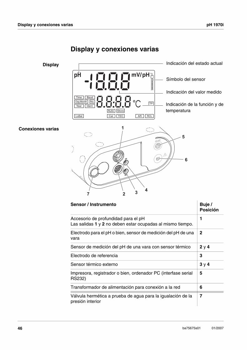
Indicación del estado actual
Indicación del valor medido
Indicación de la función y de temperatura
Símbolo del sensor
Sensor / Instrumento Buje / Posición
Accesorio de profundidad para el pHLas salidas 1 y 2 no deben estar ocupadas al mismo tiempo.
1
Electrodo para el pH o bien, sensor de medición del pH de una vara
2
Sensor de medición del pH de una vara con sensor térmico 2 y 4
Electrodo de referencia 3
Sensor térmico externo 3 y 4
Impresora, registrador o bien, ordenador PC (interfase serial RS232)
5
Transformador de alimentación para conexión a la red 6
Válvula hermética a prueba de agua para la igualación de la presión interior
7
1
34
2
5
6
7
pH 1970i Batería recargable / conexión a la red
47ba75675s01 01/2007
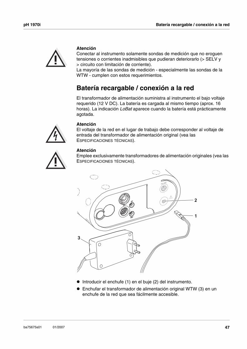
AtenciónConectar al instrumento solamente sondas de medición que no eroguen tensiones o corrientes inadmisibles que pudieran deteriorarlo (> SELV y > circuito con limitación de corriente). La mayoría de las sondas de medición - especialmente las sondas de la WTW - cumplen con estos requerimientos.
Batería recargable / conexión a la redEl transformador de alimentación suministra al instrumento el bajo voltaje requerido (12 V DC). La batería es cargada al mismo tiempo (aprox. 16 horas). La indicación LoBat aparece cuando la batería está prácticamente agotada.
AtenciónEl voltaje de la red en el lugar de trabajo debe corresponder al voltaje de entrada del transformador de alimentación original (vea las ESPECIFICACIONES TÉCNICAS).
AtenciónEmplee exclusivamente transformadores de alimentación originales (vea las ESPECIFICACIONES TÉCNICAS).
2
1
3
Introducir el enchufe (1) en el buje (2) del instrumento.
Enchufar el transformador de alimentación original WTW (3) en un enchufe de la red que sea fácilmente accesible.

Conectar el instrumento pH 1970i
48 ba75675s01 01/2007
Conectar el instrumento
MedirSumario de los modos de medición:
Funciones especiales:
AutoRead(control de deriva)
La función AutoRead verifica la estabilidad de la señal de medición (excepto al medir el potencial Redox). Activar la función AutoRead con <AR>. Para iniciar la medición AutoRead, presionar <RUN/ENTER>. Durante la medición AutoRead la indicación AR parpadea intermitentemente, hasta que la señal medida se estabiliza. La medición con AutoRead puede ser interrumpida en todo momento mediante<RUN/ENTER>, siendo registrado el valor actual.
Medición de latemperatura
durantemediciones del
valor pH
Se pueden emplear sondas de medición con y sin sensores térmicos. El instrumento reconoce el tipo de sensor térmico empleado y conecta automáticamente al modo correcto para la medición de temperatura (indicación TP).Ingreso manual de la temperatura: Ajustar la temperatura con <▲> <▼>.
Presionar la tecla <ON/OFF>.En el display aparece brevemente el test del display.Luego el instrumento cambia automáticamente al modo de medición. El display indica el valor medido actual.
Valor pHPotencial
RedoxmV<M>

pH 1970i Calibración
49ba75675s01 01/2007
CalibraciónAutoCal TEC Es una calibración completamente automática de un punto, de punto doble
o de punto triple especialmente adaptada a las soluciones tamponadas técnicas de la WTW. El medidor reconoce automáticamente las soluciones tamponadas. Dependiendo de la configuración, el instrumento indica el valor tampón nominal o el potencial actual del sensor en mV.
Soluciones tamponadas válidas (valores a 25 °C): 2,00 / 4,01 / 7,00 / 10,01
ObservaciónLa calibración con un pH de 10,01 ha sido optimizada para las soluciones tamponadas técnicas de la WTW TEP 10 Trace y TPL 10 Trace. Otras soluciones tamponadas pueden producir errores en la calibración. Las soluciones tamponadas correctas pueden ser consultadas en el catálogo de la WTW, o bien, en el Internet.
AutoCal DIN Similar a la AutoCal TEC, pero adaptada a las soluciones tamponadas según DIN 19266.
Soluciones tamponadas válidas (valores a 25 °C): 1,679 / 4,006 / 6,865 / 9,180
ConCal Es la calibración de punto doble con dos soluciones tamponadas (pH 7,0 ± 0,5 y cualquier otra solución tamponada) o bien, una calibración de un punto con una solución tamponada cualquiera, como método rápido.
Evaluación decalibración
El instrumento evalúa automáticamente la calibración después que la misma ha sido llevada a cabo. La asimetría y la pendiente son evaluadas por separado. El valor más malo de cada evaluación es indicado en el display.
ObservaciónSi hay conectada una impresora a la interfase, el instrumento imprime automáticamente un registro de calibración después de haber terminado una calibración válida.
Indicación E3Calibración inadmisible
Asimetría [mV] -15 ... +15 -20 ... +20 -25 ... +25 -30 ... +30 < -30 o bien > 30
Pendiente[mV/pH]
-60,5 ... -58 -58 ... -57 -61 ... -60,5 o -57 ... -56
-62 ... -61 o -56 ... -50
< -62 o bien > -50

Calibración pH 1970i
50 ba75675s01 01/2007
Procedimiento AutoCal TEC / AutoCal DIN:
En el siguiente ejemplo se explica la calibración AutoCal TEC. Durante la calibración AutoCal DIN en el display aparece Cd... en lugar de Ct.... En lo demás, ambos procedimientos son idénticos.
Por medio de la tecla <CAL> se selecciona la calibración AutoCal TEC (indicación Ct1) o bien, la calibración AutoCal DIN (indicación Cd1).
Conectar la sonda de medición al medidor pH.
Presionar repetidamente la tecla <CAL> hasta que aparezca la indicación Ct1 y la indicación de función Auto Cal TEC. El símbolo del sensor indica la evaluación de la última calibración (o bien, ningún símbolo cuando está aún configurado de fábrica o después de haber refijado los parámetros de medición).
Sumergir la sonda de medición del pH en la primera solución tamponada.
al medir sin sensor de temperatura: Ingresar la temperatura del la primera solución tamponada con <▲> <▼>.
Presionar <RUN/ENTER>. La medición AutoRead comienza. En el display aparece la tensión de la cadena de medición (mV) o bien, el valor nominal tamponado (vea CONFIGURACIÓN / PROGRAMACIÓN). Una vez que se haya estabilizado el valor medido, aparece Ct2.
ObservaciónEn este momento se puede interrumpir la calibración AutoCal TEC mediante <M>. Esto corresponde a una calibración de un punto. El instrumento aplica la pendiente Nernst (-59,16 mV/pH a 25 °C) y determina la asimetría de la sonda de medición.
Para continuar con la calibración de punto doble sumergir el sensor de medición del pH en la segunda solución tamponada.
al medir sin sensor de temperatura: ingresar la temperatura de la segunda solución tamponada mediante <▲> <▼>.
Presionar <RUN/ENTER>. La medición AutoRead comienza. En el display aparece el potencial del sensor de medición (mV) o bien, el valor nominal de la solución tamponada.
En el momento en que el valor medido se estabiliza, el instrumento indica la pendiente y la evaluación de la calibración de punto doble.
Presionar <RUN/ENTER>. El instrumento indica el valor de la asimetría.
Store
AR
1
LoBat nLF Lin Oxi
Tref25 Tref20
ARng
8Time
Year Ident
No.Day.Month
Baud Salcm1/K/%
RCL
REL2
pH/mV
m cmS/% mg/l
SalO
SpH
C2 4 8
T 1°C TP
REL1
Cal TEC
Auto
Store
AR
1
LoBat nLF Lin Oxi
Tref25 Tref20
ARng
8Time
Year Ident
No.Day.Month
Baud Salcm1/K/%
RCL
REL2
pH/mV
m cmS/% mg/l
SalO
SpH
C2 4 8
T 2°C TP
REL1
Cal TEC
Auto
- m cmS/% mg/l
SalO
SpH
594pHmV/
1pH
cmS/mg/l
SalO
SpH
2mV

pH 1970i Calibración
51ba75675s01 01/2007
ObservaciónEn este momento se puede interrumpir la calibración AutoCal TEC mediante <M>. Esto corresponde a una calibración de punto doble.
Para continuar con la calibración de punto triple sumergir el sensor de medición del pH en la tercera solución tamponada.
al medir sin sensor de temperatura: Ingresar la temperatura de la tercera solución tamponada con <▲> <▼>.
Presionar <RUN/ENTER>. La medición AutoRead comienza. En el display aparece el potencial del sensor de medición (mV) o bien, el valor nominal de la solución tamponada.
En el momento en que el valor medido se estabiliza, el instrumento indica la pendiente y la evaluación de la calibración de punto triple.
Presionar <RUN/ENTER>. El instrumento indica el valor de la asimetría.
Con <M> cambiar al modo de medición.
Store
AR
1
LoBat nLF Lin Oxi
Tref25 Tref20
ARng
8Time
Year Ident
No.Day.Month
Baud Salcm1/K/%
RCL
REL2
pH/mV
m cmS/% mg/l
SalO
SpH
C2 4 8
T 3°C TP
REL1
Cal TEC
Auto
- m cmS/% mg/l
SalO
SpH
588pHmV/
1pH
cmS/mg/l
SalO
SpH
2mV

Calibración pH 1970i
52 ba75675s01 01/2007
Procedimiento ConCal:
Conectar la sonda de medición al medidor pH.
Presionar repetidamente la tecla <CAL> hasta que aparezca la indicación ASY y la indicación de función Cal. El símbolo del sensor indica la evaluación de la última calibración (o bien, ningún símbolo cuando está aún configurado de fábrica o después de haber refijado los parámetros de medición).
Sumergir el sensor del pH en la primera solución tamponada (pH 7,0 ± 0,5 en la calibración de punto doble).
al medir sin sensor de temperatura: manteniendo oprimida la tecla <RUN/ENTER> ingresar la temperatura de la primera solución tamponada con <▲> <▼>.
Presionar la tecla <RUN/ENTER>.En el display aparece el valor del pH.
Ajustar el valor medido con <▲> <▼> al valor pH nominal de la solución tamponada (a la temperatura del momento).
Si el valor medido es estable, presionar la tecla <RUN/ENTER>. En el display aparece el valor de la asimetría.
Presionar la tecla <RUN/ENTER>. Aparece SLO.
ObservaciónEn este momento se puede cancelar la calibración ConCal mediante <M>. Esto corresponde a una calibración de un punto. El instrumento aplica la pendiente Nernst (-59,16 mV/pH a 25 °C) y determina la asimetría de la sonda de medición.
Para continuar con la calibración de punto doble sumergir el sensor de medición del pH en la segunda solución tamponada.
al medir sin sensor de temperatura: manteniendo oprimida la tecla <RUN/ENTER> ingresar la temperatura de la segunda solución tamponada mediante <▲> <▼>.
Presionar <RUN/ENTER>.
Ajustar el valor medido con <▲> <▼> al valor pH nominal de la solución tamponada (a la temperatura del momento).
Si el valor medido es estable, presionar la tecla <RUN/ENTER>. El instrumento indica el valor de la pendiente y la evaluación de la calibración.
Presionar <RUN/ENTER>. El instrumento indica el valor de la asimetría.
Con <M> cambiar al modo de medición.
TEC
Auto Store
AR
1
LoBat nLF Lin Oxi
Tref25 Tref20
ARng
8Time
Year Ident
No.Day.Month
Baud Salcm1/K/%
RCL
REL2
pH/mV
m cmS/% mg/l
SalO
SpH
A2 4 8
SY°C TP
REL1
Cal
7
TEC
Auto Store
ARLoBat nLF Lin Oxi
Tref25 Tref20
ARng
8Time
Year Ident
No.Day.Month
Baud Salcm1/K/%
RCL
REL2
pH/mV
m cmS/% mg/l
SalO
SpH
72 4 8
02°C TP
REL1
Cal
4
TEC
Auto Store
ARLoBat nLF Lin Oxi
Tref25 Tref20
ARng
8Time
Year Ident
No.Day.Month
Baud Salcm1/K/%
RCL
REL2
pH/mV
m cmS/% mg/l
SalO
SpH
S2 4 8
L O°C TP
REL1
Cal
7
TEC
Auto Store
ARLoBat nLF Lin Oxi
Tref25 Tref20
ARng
8Time
Year Ident
No.Day.Month
Baud Salcm1/K/%
RCL
REL2
pH/mV
m cmS/% mg/l
SalO
SpH
$2 4 8
58°C TP
REL1
Cal
- m cmS/% mg/l
SalO
SpH
594pHmV/
C T1pH/
m cmS/% mg/l
SalO
SpH
3mV

pH 1970i Archivar en memoria
53ba75675s01 01/2007
Archivar en memoriaEl instrumento dispone de una memoria interna. Su capacidad alcanza para archivar hasta 800 conjuntos de datos.
Archivarmanualmente en
memoria
En el modo de medición, presionar la tecla <STO> (indicación No. con el número de la siguiente posición libre). Luego presionar <RUN/ENTER> e ingresar el No. de identificación con <▲> <▼>. Terminar el archivo con <RUN/ENTER>. El instrumento cambia al modo de medición.
Archivar datos enmemoria en forma
automática Int 1
El intervalo (Int 1) determina el tiempo que transcurre entre dos archivos consecutivos automáticos. Para ajustar el intervalo de almacenamiento, presionar <STO>manteniendo oprimida la tecla <RUN/ENTER> (indicación Int 1) y asignar el intervalo deseado mediante <▲> <▼>. Luego, presionar la tecla <RUN/ENTER>. Aparece la cantidad disponible de posiciones de almacenamiento. Presionar nuevamente<RUN/ENTER> e ingresar el No. de ident. con <▲> <▼>. Con <RUN/ENTER> cambiar al modo de medición activado de último. La función de archivo automático está activada (indica Auto Store).
Llamar los datos archivados en memoriaCon la tecla <RCL> se pueden acceder a los datos archivados. Presionando repetidas veces la tecla <RCL> se tienen las siguientes funciones:
Iniciar la transferencia de datos con <RUN/ENTER>.
Borrar los datos archivados en memoriaDesconectar el instrumento. Presionar la tecla <STO> y mantenerla oprimida. Presionar la tecla <ON/OFF>. Con <RUN/ENTER> confirmar el proceso de borrado o bien, cancelarlo presionando una tecla cualquiera.
Transferir datosTransferir los
datosmanualmente
Presionar la tecla <RUN/ENTER> encontrándose en el modo de medición. Así Ud. puede iniciar en cualquier momento la transmisión de datos hacia la interfase serial, independientemente de los intervalos asignados.
StO dISP Presentar en el display los datos archivados en memoria
StO SEr Transferir los datos archivado en memoria a la interfase serial
CAL dISP Presentar en el display los datos de calibración
CAL SEr Transferir los datos de calibración a la interfase serial

Registrador (salida analógica) pH 1970i
54 ba75675s01 01/2007
Transferenciaautomática de los
datos Int 2
El intervalo de transferencia de datos (Int 2) determina el período de tiempo entre dos transferencias consecutivas automáticas de datos. Después que ha transcurrido el intervalo asignado, el conjunto actual de datos es transferido a la interfase. Para asignar el intervalo de tiempo entre dos transferencias automáticas consecutivas <RCL>, manteniendo oprimida la tecla, presionar <RUN/ENTER> (indicación Int 2). A continuación asignar el intervalo con <▲> <▼>.
Registrador (salida analógica)A través de la salida analógica puede Ud. transferir los datos a un registrador. Conecte el registrador a la salida analógica mediante el cable de interfase AK323. La salida de datos cambia automáticamente al registrador.
ObservaciónLos datos entregados a la salida analógica corresponden al valor indicado en el display (pH 7.00 es entregado con el valor 700 mV ).
ConfigurarObservaciónUd. puede abandonar el menú de configuración en todo momento mediante <M>. Los parámetros modificados han sido archivados en memoria.
Configuración (los valores de fábrica están en negrita):
Desconectar el instrumento
Manteniendo oprimida la tecla <M>, presionar la tecla <ON/OFF>.
Fijar la cuota de transmisión (en baud) con <▲> <▼>. Valores a elección: 1200, 2400, 4800, 9600 Baud.
Luego, presionar la tecla <RUN/ENTER>.
Asignar la indicación deseada durante la calibración del pH, mediante <▲> <▼>.Valores a elección: Valor nominal de la solución tamponada (/pH) o bien, potencial actual del sensor de medición (mV).
Luego, presionar la tecla <RUN/ENTER>.
Asignar el intervalo de calibración deseado mediante <▲> <▼>.Valores a elección: 1 ... 7 ... 999 d.
Luego, presionar la tecla <RUN/ENTER>.
Ajustar la fecha y la hora, paso a paso, con <▲> <▼>. Confirmar cada ingreso presionando la tecla <RUN/ENTER>.
Al presionar la tecla <RUN/ENTER> por última vez, el instrumento cambia al modo de medición que estaba activo de último.
SaTP°CYear Ident
No.Day.Month
Time cm1/K/%8 0 04
Baud
Sal
mg/lO
TP°C
S
Year Ident
No.Day.Month
SalCTime Baud cm1/
K/%
mV
m cmS/%C
I S P
ALd
pH pH/
TP
Sal1
O
cm1/
4 TP°C
cmS/Sal
%
S%
mmg/l
Year Ident
No.Day.Month
SalBaud
K/
pH/mV
7
3n td
ITime
pH
Day.Month 0 9 0 4

pH 1970i Reajustar al valor inicial (Reset)
55ba75675s01 01/2007
Reajustar al valor inicial (Reset)Usted puede inicializar por separado los parámetros de medición y la configuración (reajustar los parámetros a los valores iniciales de fábrica).
Parámetros demedición
Los siguientes parámetros de medición pueden ser reajustados al valor inicial de fábrica:
Parámetros deconfiguración
Los siguientes parámetros de configuración (InI) pueden ser reajustados al valor inicial de fábrica:
Proceso de reajuste al valor inicial:
Modo de medición pH
Pendiente -59,16 mV/pH
Asimetría 0 mV
Ingreso manual de la temperatura: 25°C
Cuota de transmisión (en baud) 4800
Indicación durante la calibración del pH
Valor nominal de la solución tamponada
Intervalo 1(archivar en memoria automáticamente)
OFF
Intervalo 2(para transferencia de datos) OFF
Con la tecla <RUN/ENTER> oprimida, presionar la tecla <CAL>.
Para reajustar al valor inicial los parámetros de medición, con <▲> <▼> seleccionar YES y con <RUN/ENTER>confirmar, o bien,
continuar con los otros parámetros de configuración (InI) con la tecla <RUN/ENTER>, sin inicializar los parámetros.
Después de los parámetros de configuración InI el instrumento cambia al modo de medición que estaba activo de último.
O
Day.Month 0 9Time
Icm1/
TP°C
cmS/Sal
%
S%
mmg/l
Year Ident
No.
SalBaud
K/
pH/mV
n o
iinpH

Eliminación / desaprovisionamiento pH 1970i
56 ba75675s01 01/2007
Eliminación / desaprovisionamientoQuite la batería del instrumento y entréguela en un lugar de recolección de acuerdo a las disposiciones legales de eliminación de basura.
Sacar la batería
Desatornillar los elementos de fijación (1).
Ejerciendo firmemente presión contra la cubierta de las conexiones varias, sacar el instrumento de su carcasa. A continuación sacar la batería (2) y cortar el cable de conexión.
Ni-Cd Cd
1
1
2

pH 1970i Especificaciones técnicas
57ba75675s01 01/2007
Especificaciones técnicas
Dimensiones aprox. 90 x 200 x 190 mm
Peso aprox. 1,5 kg (sin transformador de alimentación)
Diseño mecánico Tipo de protección IP 67
Seguridadeléctrica
Clase de protección III
Marca detipificación
CE
Condicionesmedioambientales
de almacenamiento - 25 °C ... + 65 °C
de funcionamiento -10 °C ... + 55 °C
clase climática 2
Suministroeléctrico
Batería Batería recargable de niquel-cadmio (NiCd)
Vida útil aprox. 600 horas con la batería completamente cargada
Transformador de alimentación para conexión a la red(cargador)
Para todos los transformadores de alimentación vale:conexión de sobretensión máxima según categoría II
Transformador de alimentación con enchufes europeo, americano, inglés, australiano:FRIWO FW7555M/09, 15.1432Friwo Part. No. 1883259Input: 100 ... 240 V ~ / 50 ... 60 Hz / 400 mAOutput: 9 V = / 1,5 A
Interfaseserial
(cable AK 340/B obien, AK 325/S)
Tipo RS232, salida de datos
Cuota de transmisión (en baud)
ajustable: 1200, 2400, 4800, 9600 Baud
Bits de datos 8
Bits de parada 2
Paridad sin (none)
Handshake RTS/CTS + Xon/Xoff
Longitud del cable max. 15m

Especificaciones técnicas pH 1970i
58 ba75675s01 01/2007
Rangos de medición, resolución, exactitud
* en el caso de mediciones en el rango de ± 2 pH alrededor de un punto de calibración
Salida analógica(cable AK 323/S)
Conmutación automática al conectar el cable de registro AK 323/S.
Señal de salida pH -200 ... +1999 mV la banda entre - 2,00 ... + 19,99
Señal de salida mV -1999 ... +1999 mV para la banda entre -1999 ... +1999 mV
Exactitud ± 0,5 % del valor indicado
Resistencia interna < 5 Ohm (limitación de la corriente a max. 0,2 mA de la corriente de salida)
Directivas ynormas
aplicadas
CEM Directiva de la Comunidad Europea 89/336/CEEN 61326-1:1998EN 61000-3-2 A14:2000EN 61000-3-3:1995FCC Class A
Clase de seguridad del aparato
Directiva de la Comunidad Europea 73/23/CEEN 61010-1 A2:1995
Clase climática VDI/VDE 3540
Tipo de protección IP EN 60529:1991
Dimensión Rango de medición
Resolución Exactitud (± 1 dígito)
pH - 2,00 ... + 19,99 0,01 ± 0,01 *
U [mV] - 199,9 ... + 199,9- 1999 ... + 1999
0,11
± 0,5± 1
T [°C] - 5,0 ... + 105,0 0,1 ± 0,1
Ingreso manual
de la temperatura
Dimensión Rango Paso
Tmanual [°C] - 20 ... + 130 1


Wissenschaftlich-Technische Werkstätten GmbH
Dr.-Karl-Slevogt-Straße 1D-82362 Weilheim
Germany
Tel: +49 (0) 881 183-0+49 (0) 881 183-100
Fax: +49 (0) 881 183-420E-Mail: [email protected]: http://www.WTW.com