Pex Design Guide
128
Transcript of Pex Design Guide

5/11/2018 Pex Design Guide - slidepdf.com
http://slidepdf.com/reader/full/pex-design-guide-55a0d1ab10986 1/128

5/11/2018 Pex Design Guide - slidepdf.com
http://slidepdf.com/reader/full/pex-design-guide-55a0d1ab10986 2/128
5/11/2018 Pex Design Guide - slidepdf.com
http://slidepdf.com/reader/full/pex-design-guide-55a0d1ab10986 3/128
DESIGN GUIDEResidential PEX Water
Supply Plumbing SystemsPrepared for
Plastics Pipe Institute, Inc (PPI)
105 Decker CourtSuite 825
Irving, TX 75062www.plasticpipe.org
and
Plastic Pipe and Fittings Association (PPFA)
800 Roosevelt Road, Bldg. C, Ste. 312Glen Ellyn, IL 60137www.ppfahome.org
and
Partnership for Advancing Technology in Housing
451 7th Street, SWWashington, DC 20410
www.pathnet.org
Prepared by
NAHB Research Center, Inc.400 Prince George’s Boulevard
Upper Marlboro, MD 20774www.nahbrc.org
November 2006
This document was developed as the result of a consensus process involving the Plastic Pipe Institute, the Plastic and Plastic
Pipe and Fitting Association, and representatives from numerous piping and tting manufacturers. It was prepared by the
NAHB Research Center, with support and research from the Partnership for Advancing Technology in Housing (PATH).

5/11/2018 Pex Design Guide - slidepdf.com
http://slidepdf.com/reader/full/pex-design-guide-55a0d1ab10986 4/128
Acknowledgements
We would like to thank the following principal
contributors to this Guide:
Plastic Pipe and Fittings Association
Glen Ellyn, IllinoisRichard Church, Mike Cudahy
Plastics Pipe InstituteIrving, Texas
Camille Rubeiz
Rehau Inc.
Leesburg, Virginia
Lance MacNevin
Uponor
Apple Valley, Minnesota
Randy Knapp
Vanguard Piping Systems
McPherson, Kansas
Gary Morgan
Viega Wichita, Kansas
Christina Smith
WattsRadiantSpringeld, Missouri
Chris Haldiman
Zurn Plumbing Products GroupCommerce, Texas
Gary Runyan
Department of Housing and Urban Development (HUD)
Washington D.C.Dana Bres
NAHB Research Center Upper Marlboro, Maryland
Robert Fuller, Michael Grothe, Megan Inouye,
Shawn Martin, Joseph Wiehagen. Anne Holtz andKim Warren for editorial review, and Edith Crane
and Pam Eggleston for layout and design.
We would also like to acknowledge the supportof the Partnership for Advancing Technology in
Housing (PATH) and the material support of the
Delta Faucet Company.
Copyright
Copyright © 2006 NAHB Research Center,
Inc., Plastics Pipe Institute, Plastic Pipe andFittings Association. All rights reserved.
Disclaimer
Neither the NAHB Research Center,
Inc, the Plastics Pipe Institute, the PlasticPipe and Fitting Association, the U.S.
Department of Housing and Urban
Development, nor any person acting inits behalf, makes any warranty, express
or implied, with respect to the use of anyinformation, apparatus, method, or process
disclosed in this publication or that such usemay not infringe privately owned rights, orassumes any liabilities with respect to the
use of, or for damages resulting from theuse of, any information, apparatus, method,
or process disclosed in this publication,
or is responsible for statements made oropinions expressed by individual authors.
For Further Information:
Please consult the following websites forthe latest version of this publication.
Plastics Pipe Institutehttp://www.plasticpipe.org/
Plastic Pipe and Fittings Associationhttp://www.ppfahome.org/
ToolBase.org
http://www.toolbase.org/
5/11/2018 Pex Design Guide - slidepdf.com
http://slidepdf.com/reader/full/pex-design-guide-55a0d1ab10986 5/128
Table f Ctets
Chapter 1 – INTRODUCTION ............................. 1Objective .......................................................................................................1Background ...................................................................................................1Applications...................................................................................................3How to Use the Design Guide .................................................................3
Chapter 2 – ADVANTAGES.................................. 5Ease of Installation .......................................................................................5Durability .......................................................................................................5Cost Effectiveness .......................................................................................5Energy Efciency ..........................................................................................5Noise Reduction ..........................................................................................6Water Conservation ...................................................................................6Environmentally Sound...............................................................................6
Chapter 3 – MATERIAL PROPERTIES ................ 7Temperature and Pressure ........................................................................8Flexibility........................................................................................................8Noise and Water Hammer Resistance...................................................8Resistance to Freeze Damage...................................................................9Chlorine Resistance ....................................................................................9Corrosion Resistance .............................................................................. 10Ultraviolet (UV) Resistance ................................................................... 10Inert Material – Safe for Drinking Water ............................................11PEX Piping Dimensions and Flow Characteristics.............................11
Chapter 4 – CODE ACCEPTANCE ................... 15International Residential Code (IRC-2003).........................................15International Plumbing Code (IPC 2003).............................................16National Standard Plumbing Code (NSPC 2003) ..............................17Uniform Plumbing Code (UPC-2003)...................................................17International Code Council (ICC) Evaluation Service Reports
(ESR) and Evaluation Reports (ER)....................................................17International Association of Plumbing and Mechanical Ofcials
(IAPMO) Guide Criteria ..................................................................... 18C904-06 American Waterworks Association (ANSI/AWWA
C904-06)................................................................................................. 18Chapter 5 – JOINING METHODS ..................... 19
Cold Expansion Fittings with PEX Reinforced Rings ...................... 20Cold Expansion Fittings with Metal Compression Sleeves ........... 20Metal or Plastic Insert Fittings................................................................21
Copper Crimp Ring...............................................................................21Stainless Steel Clamp ........................................................................... 22Stainless Steel Sleeve............................................................................ 22
Push Type Fittings ..................................................................................... 23Standard Specications for Fittings ...................................................... 24
ASTM F 1807: Standard Specication for Metal Insert Fittings Utilizing a Copper Crimp Ring for SDR9 Cross-Linked Polyethylene (PEX) Tubing ............................................................ 24

5/11/2018 Pex Design Guide - slidepdf.com
http://slidepdf.com/reader/full/pex-design-guide-55a0d1ab10986 6/128
ASTM F 1960: Standard Specication for Cold Expansion
Fittings with PEX Reinforcing Rings for Use with Cross-Linked Polyethylene (PEX) Tubing ............................................... 24
ASTM F 2080: Standard Specication for Cold Expansion
Fittings with Metal Compression Sleeves for Use with PEX Pipe .............................................................................................. 24
ASTM F 2098: Standard Specication for Stainless SteelClamps for Securing SDR9 Cross-Linked Polyethylene (PEX)Tubing to Metal Insert Fittings ...................................................... 24
ASTM F 2159: Standard Specication for Plastic Insert Fittings
Utilizing a Copper Crimp Ring for SDR9 Cross-Linked Polyethylene (PEX) Tubing ............................................................ 25
ASTM F 2434: Standard Specication for Metal Insert Fittings
Utilizing a Copper Crimp Ring for SDR9 PEX Tubing and SDR9 PEX-AL-PEX Tubing.............................................................. 25
IAPMO – IGC 188: Removable and Non-Removable Push Fit Fittings.................................................................................................. 25
ASSE Standard – 1061.......................................................................... 25
Chapter 6 – TYPES OF PEX PLUMBING SYSTEMS .............................................................. 27
Trunk and Branch .................................................................................... 28Home-Run .................................................................................................. 29Remote Manifold....................................................................................... 30
Chapter 7 – DESIGN............................................ 31Consult Local Codes ................................................................................31Optimize Home Designs ....................................................................... 32Select Piping System Design................................................................... 33General Rankings of the Systems for Key Factors ........................... 34
Example Layouts ....................................................................................... 35
Colonial Layout.................................................................................. 36Ranch Layout...................................................................................... 39Townhouse Layout............................................................................ 42Condominium Layout....................................................................... 45
Performance Verication Laboratory Testing ................................... 48Industry Technical Support .................................................................... 48Plan Pipe Routing, Manifold, and Valve Locations............................. 48
Chapter 8 – PERFORMANCE DATA ................. 51System Performance Comparison.........................................................51Test System Design and Set-up ..............................................................51
Plumbing System Pressure and Flow Test Results ............................ 54Wait Time for Hot Water.......................................................................61Test Summary ........................................................................................... 62
Chapter 9 – INSTALLATION ............................. 63Important Notice ..................................................................................... 63Revision Policy ........................................................................................... 64
5/11/2018 Pex Design Guide - slidepdf.com
http://slidepdf.com/reader/full/pex-design-guide-55a0d1ab10986 7/128
Manual Content & Use............................................................................ 65
Parallel Water Distribution Manifold Plumbing (Home-Run)
Protection of Tubing and Fittings from UV Exposure after the
Insert Fitting with a Black Copper Crimp Ring
Joining Procedures Utilizing ASTM F 1960 Fittings and
Other Uses of Cross-Linked Polyethylene (PEX) Tubing............... 65Tubing Identication................................................................................. 66Fitting Identication ................................................................................. 67Applicable Standards ................................................................................ 67Limitations on PEX Use .......................................................................... 67TUBING INSTALLATION PRACTICES............................................. 68General Installation .................................................................................. 68Bending the Tubing................................................................................... 69Handling and Storing Tubing and Fittings............................................ 69Tubing Supports: ....................................................................................... 70Selection and Inspection ......................................................................... 70Support Spacing and Location .............................................................. 70Horizontal Tubing Support Spacing...................................................... 70Expansion/Contraction of Tubing..........................................................71Hydraulic Shock (Pressure Surge) ........................................................71Manifold Plumbing Systems .................................................................... 72
Systems .................................................................................................... 73Thawing PEX Tubing Systems ................................................................ 75Pressure Testing and Inspection of the Completed System .......... 76Disinfection of Potable Water Systems ............................................. 76Buried PEX Water Service Lines.......................................................... 77Fittings ......................................................................................................... 77Trench Preparation .................................................................................. 77Laying the Tubing ...................................................................................... 77Penetrating Foundation or Basement Walls ...................................... 77Slab-on-Grade Installation...................................................................... 78Laying and Supporting Tubing under Slab ........................................... 78
Pour ......................................................................................................... 78Backlling .................................................................................................... 78Technical Data ........................................................................................... 79Tubing Dimensions and Weights (ASTM F 876/F 877).................... 79Friction Losses........................................................................................... 79Friction Loss and Velocity vs. Flow Rate ............................................ 80PEX Plumbing Tubing (CTS) (ASTM F 876/F 877) ............................ 80Connection (Transition) to Other Piping Materials ....................... 81
Joining Procedures Utilizing Metallic or Polymer Insert Fittings . 81(ASTM F 1807 OR ASTM F 2159)..................................................... 81
Making a Connection ............................................................................... 81Incorrect Connections ............................................................................ 81Tools and Rings ......................................................................................... 82
PEX Rings................................................................................................ 82ASTM F 1960 Connections, Helpful Hints ......................................... 83Tools ........................................................................................................... 84
5/11/2018 Pex Design Guide - slidepdf.com
http://slidepdf.com/reader/full/pex-design-guide-55a0d1ab10986 8/128
Joining Procedures utilizing ASTM F 2080 Fittings andCompression Sleeves ........................................................................... 84
Summary ..................................................................................................... 84Procedure ................................................................................................... 84Other Fitting Systems.............................................................................. 85
Chapter 10 – TESTIMONIALS ........................... 87Chapter 11 – OTHER APPLICATIONS ............. 91Radiant Floor Heating Systems ..............................................................91Municipal Water Service Pipe.................................................................91Snow and Ice Melt .................................................................................... 92Turf Conditioning ..................................................................................... 92Fire Suppression ...................................................................................... 93
Appendix A – PERFORMANCE TEST SETUP AND DATA ........................................................... 95Appendix B – INSTALLATION CHECKLIST . 105Appendix C – RESOURCES .............................. 107
Articles and Reports.............................................................................. 107Manufacturers’ Information .................................................................. 111Plastics Pipe Institute (PPI) Technical Notes ....................................113
GLOSSARY .........................................................115

5/11/2018 Pex Design Guide - slidepdf.com
http://slidepdf.com/reader/full/pex-design-guide-55a0d1ab10986 9/128
List f Figes
Figure 5.1 – Cold Expansion Polymer Fitting with PEX Reinforced Ring ............ 20Figure 5.2 – Cold Expansion Metal Fitting with PEX Reinforced Ring................. 20 Figure 5.3 – Cold Expansion Fitting with Metal Compression Sleeve.................. 20Figure 5.4 – Metal Insert Fitting with Copper Crimp Ring ..................................... 21Figure 5.5 – Plastic Insert Fitting with Copper Crimp Ring.................................... 21Figure 5.6 – Metal Insert Fitting with O-rings and Copper Crimp Ring.............. 21Figure 5.7 – Metal Insert Fitting with Stainless Steel Clamp Band ........................ 22 Figure 5.8 – Metal Insert Fitting with Stainless Steel Clamp Sleeve...................... 22 Figure 5.9 – Metal Insert Fitting with Stainless Steel Press Sleeve........................ 22Figure 5.10 – Push Type Fitting....................................................................................... 23Figure 6.1 – PEX Pipes in a Trunk and Branch System Design ............................... 28Figure 6.2 – PEX Pipes in a Home-Run Design.......................................................... 29Figure 6.3 – PEX Pipes in a Remote Manifold Design ............................................. 30Figure 7.1 – Trunk and Branch Isometric Riser for the Colonial House ............ 37Figure 7.2 – Home-Run Isometric Riser for the Colonial House ......................... 37Figure 7.3 – Remote Manifold Isometric Riser for the Colonial House ............. 38Figure 7.4 – Trunk and Branch Isometric Riser for the Ranch House ................ 40Figure 7.5 – Home-Run Isometric Riser for the Ranch House ............................. 40Figure 7.6 – Remote Manifold Isometric Riser for the Ranch House .................. 41Figure 7.7 – Trunk and Branch Isometric Riser for the Townhouse .................... 43Figure 7.8 – Home-Run Isometric Riser for the Townhouse ................................ 43Figure 7.9 – Remote Manifold Isometric Riser for the Townhouse ..................... 44Figure 7.10 – Trunk and Branch Isometric Riser for the Condominium ............. 46Figure 7.11 – Home-Run Isometric Riser for the Condominium .......................... 46Figure 7.12 – Remote Manifold Isometric Riser for the Condominium .............. 47Figure 8.1 – Fixture Layout for Laboratory Testing.................................................. 52Figure 8.2 – Laboratory Test Set-up with Five Outlets, Hot Water Tank,
and T&B System ............................................................................................................. 53Figure 8.3 – The Test Fixture (Shower) with Flow and Pressure
Sensors Installed............................................................................................................. 53Figure 8.4 – Pressure Drop Comparison, 100’ Distance to TF ............................. 60Figure 8.5 – Pressure Drop Comparison, 60’ Distance to TF ............................... 60Figure 8.6 – Comparison of Hot Water Delivery Time .......................................... 61Figure 11.1 – Radiant Floor Heating Piping .................................................................. 91Figure 11.2 – Snow and Ice Melt Piping for a Driveway .......................................... 92Figure 11.3 – Turf Conditioning in a Stadium.............................................................. 92Figure 11.4 – Fire Sprinkler with PEX Piping............................................................... 93 Figure A.1 – Water System Test Piping Layout – Trunk and Branch,
60’ to TF........................................................................................................................... 95Figure A.2 – Water System Test Piping Layout – Trunk and Branch,
100’ to TF ........................................................................................................................ 96
Figure A.3 – Water System Test Piping Layout – Home-Run, 60’ to TF............. 96Figure A.4 – Water System Test Piping Layout – Home-Run, 100’ to TF........... 97Figure A.5 – Water System Test Piping Layout – Remote Manifolds,
60’ to TF........................................................................................................................... 97Figure A.6 – Water System Test Piping Layout – Remote Manifolds,
100’ to TF ........................................................................................................................ 98
5/11/2018 Pex Design Guide - slidepdf.com
http://slidepdf.com/reader/full/pex-design-guide-55a0d1ab10986 10/128
10
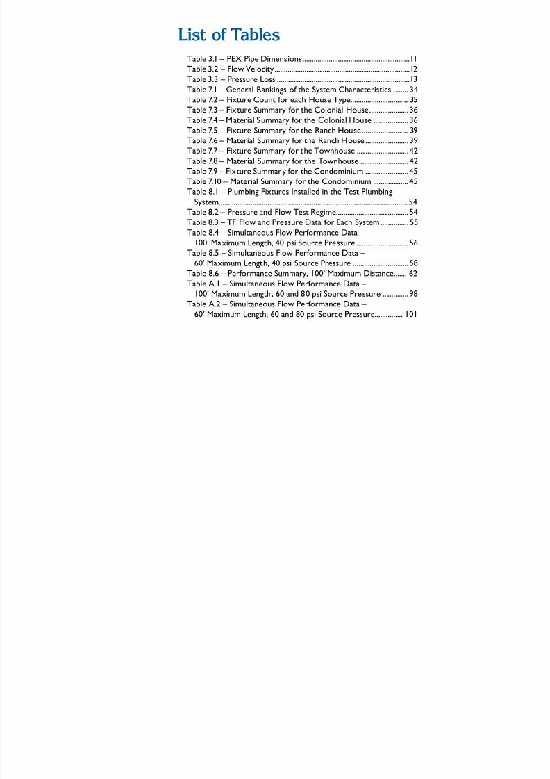
List f Tables
Table 3.1 – PEX Pipe Dimensions..........................................................11Table 3.2 – Flow Velocity .........................................................................12Table 3.3 – Pressure Loss ........................................................................13Table 7.1 – General Rankings of the System Characteristics ........ 34 Table 7.2 – Fixture Count for each House Type............................... 35Table 7.3 – Fixture Summary for the Colonial House..................... 36Table 7.4 – Material Summary for the Colonial House ................... 36Table 7.5 – Fixture Summary for the Ranch House ......................... 39Table 7.6 – Material Summary for the Ranch House ....................... 39Table 7.7 – Fixture Summary for the Townhouse ............................ 42Table 7.8 – Material Summary for the Townhouse .......................... 42Table 7.9 – Fixture Summary for the Condominium ....................... 45Table 7.10 – Material Summary for the Condominium ................... 45Table 8.1 – Plumbing Fixtures Installed in the Test Plumbing
System...................................................................................................... 54Table 8.2 – Pressure and Flow Test Regime....................................... 54Table 8.3 – TF Flow and Pressure Data for Each System ............... 55Table 8.4 – Simultaneous Flow Performance Data –
100’ Maximum Length, 40 psi Source Pressure ............................ 56
Table 8.5 – Simultaneous Flow Performance Data – 60’ Maximum Length, 40 psi Source Pressure .............................. 58
Table 8.6 – Performance Summary, 100’ Maximum Distance....... 62Table A.1 – Simultaneous Flow Performance Data –
100’ Maximum Length, 60 and 80 psi Source Pressure .............. 98Table A.2 – Simultaneous Flow Performance Data –
60’ Maximum Length, 60 and 80 psi Source Pressure............... 101

5/11/2018 Pex Design Guide - slidepdf.com
http://slidepdf.com/reader/full/pex-design-guide-55a0d1ab10986 11/128
InTroduCTIo
Objective
This Design Guide provides the information and resources necessary to design and installcross-linked polyethylene (PEX) water supply systems in residential buildings. It includescomprehensive design concepts and installation guidelines to increase the acceptance and
proper use of PEX. This document is targeted to meet the needs of home builders, designers,and trade contractors. Its purpose is to introduce potential users to PEX and to enablecurrent users to optimize their PEX plumbing and minimize system costs. In addition, it willallow code inspectors and homeowners to become familiar with the applications, performance
characteristics, and benets of PEX water supply systems.
Background
Cross-linked polyethylene (PEX) is a high-temperature, exible, polymer pipe. Cross-linking
technology was rst developed in Europe and has since come into use around the world for
a variety of applications. PEX has a 30-year history of successful use in the European marketwith extensive testing for durability and material performance. It was rst introduced in North
America in 1984 where it has been primarily used for radiant oor heating, and more recently,
for domestic water distribution systems. It is approved for potable hot and cold water supplysystems as well as hydronic heating systems in all model plumbing and mechanical codes acrossthe United States and Canada.
The comparison of PEX to polybutylene piping (PB) appears to be a major obstacle tomainstream acceptance by some code ofcials, trade contractors, and homeowners. But not all
plastics are the same, just as not all metals are the same. Polymer ttings for PEX pipe are far
more robust and reliable than those used for PB. A result of modern polymer technology, PEXpiping performs in ways that provide superior reliability, durability, and safety. Also, currenttesting requirements for PEX are much more stringent than when PB piping was accepted and
installed in housing.
1

5/11/2018 Pex Design Guide - slidepdf.com
http://slidepdf.com/reader/full/pex-design-guide-55a0d1ab10986 12/128
2
Chapte 1 – InTroduCTIon
The PEX piping industry is highly regulated. Standards, specications, and code requirements
dene tight material and production quality controls. Continuous-use temperature ratings
as high as 200ºF (93ºC) are required as well as standardized chlorine resistance testing toensure that the piping will withstand the most aggressive drinking water conditions. Nationallyaccredited, third-party certication agencies require strenuous quality control testing, including
random plant inspections and annual monitoring testing. There are numerous opportunities for more widespread use of PEX pipe in the U.S. residential market. The development of manifolds and parallel plumbing systems for exible piping has
helped to advance its use. All major residential building codes permit the use of PEX piping,
but obstacles to its acceptance still remain. There is anecdotal and research information thatshows:
• Some plumbers are reluctant to use PEX piping due to a lack of experience with installation
methods and design requirements
• Some jurisdictions prohibit the use of PEX piping for water supply plumbing even thoughPEX pipe is approved for use in all model codes
• Codes were originally written for rigid trunk and branch systems; while they have now beenamended to include PEX piping systems, they do not provide many system design details
• There is a perception among some that PEX piping systems are inferior as a buildingproduct, generally based on knowledge of past failures of PB piping systems.
Although these hurdles exist, the following are among the many benets of PEX piping systems.
• Ease of Installation – PEX pipe uses mechanical connections eliminating the need for
solders, ames, and chemicals. Its exible nature allows it to bend around obstructions. Use
of manifolds can speed installation and improve performance.
• Corrosion Resistance – PEX piping will not pit or stress corrode.
• Scaling Resistance – PEX pipe’s smooth interior walls and chemical properties make itresistant to mineral build-up.
• Cost Effectiveness – PEX plumbing systems are less labor intensive and can optimizesystem performance.
• Availability of Pipe Sizes – PEX piping is available in a wide range of diameters.
• Energy Efciency – PEX piping minimizes heat transmission through the pipe wall.
• Resistance to Freeze Damage – Under most circumstances, water in the pipe can be
frozen and thawed without damaging the pipe.
• Water Conservation – Well designed PEX plumbing systems can reduce the wait time for
hot water to reach the xture.
• Environmentally Sound – PEX is an inert material and does not contain volatile organiccompounds (VOCs).
• Certication – PEX pipes and ttings must meet strict performance requirements.
2
5/11/2018 Pex Design Guide - slidepdf.com
http://slidepdf.com/reader/full/pex-design-guide-55a0d1ab10986 13/128
3
Chapte 1 – InTroduCTIo
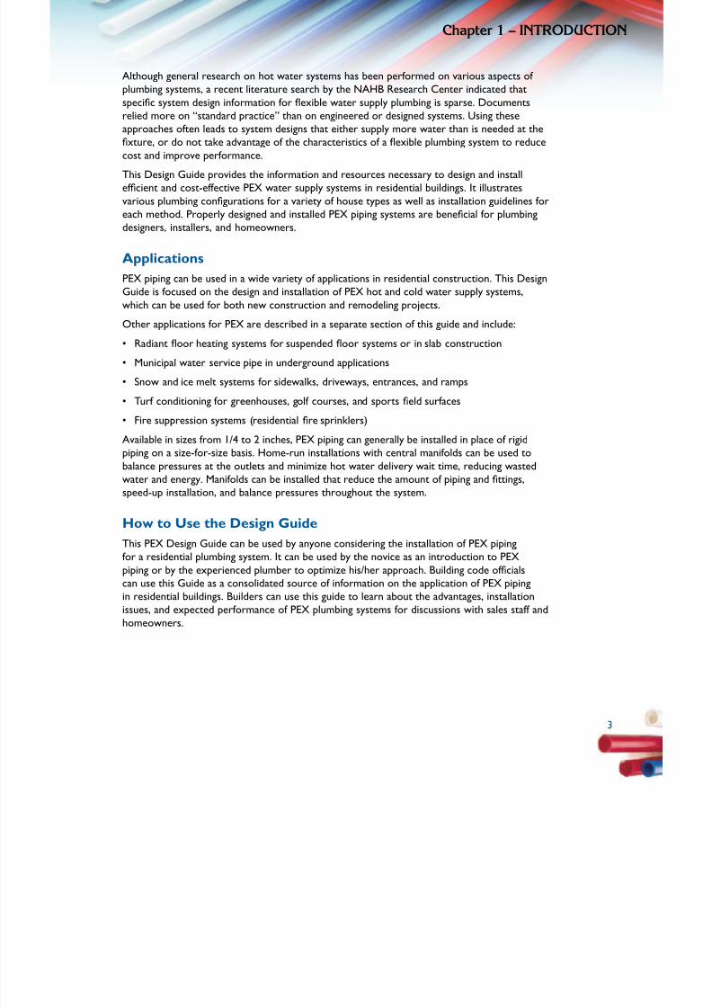
Although general research on hot water systems has been performed on various aspects of plumbing systems, a recent literature search by the NAHB Research Center indicated that
specic system design information for exible water supply plumbing is sparse. Documents
relied more on “standard practice” than on engineered or designed systems. Using theseapproaches often leads to system designs that either supply more water than is needed at thexture, or do not take advantage of the characteristics of a exible plumbing system to reduce
cost and improve performance. This Design Guide provides the information and resources necessary to design and install efcient and cost-effective PEX water supply systems in residential buildings. It illustrates
various plumbing congurations for a variety of house types as well as installation guidelines for
each method. Properly designed and installed PEX piping systems are benecial for plumbing
designers, installers, and homeowners.
Applications
PEX piping can be used in a wide variety of applications in residential construction. This DesignGuide is focused on the design and installation of PEX hot and cold water supply systems,
which can be used for both new construction and remodeling projects.
Other applications for PEX are described in a separate section of this guide and include:
• Radiant oor heating systems for suspended oor systems or in slab construction
• Municipal water service pipe in underground applications
• Snow and ice melt systems for sidewalks, driveways, entrances, and ramps
• Turf conditioning for greenhouses, golf courses, and sports eld surfaces
• Fire suppression systems (residential re sprinklers)
Available in sizes from 1/4 to 2 inches, PEX piping can generally be installed in place of rigid
piping on a size-for-size basis. Home-run installations with central manifolds can be used tobalance pressures at the outlets and minimize hot water delivery wait time, reducing wastedwater and energy. Manifolds can be installed that reduce the amount of piping and ttings,
speed-up installation, and balance pressures throughout the system.
How to Use the Design Guide
This PEX Design Guide can be used by anyone considering the installation of PEX pipingfor a residential plumbing system. It can be used by the novice as an introduction to PEXpiping or by the experienced plumber to optimize his/her approach. Building code ofcials
can use this Guide as a consolidated source of information on the application of PEX pipingin residential buildings. Builders can use this guide to learn about the advantages, installation
issues, and expected performance of PEX plumbing systems for discussions with sales staff andhomeowners.
3
5/11/2018 Pex Design Guide - slidepdf.com
http://slidepdf.com/reader/full/pex-design-guide-55a0d1ab10986 14/128
4
Chapte 1 – InTroduCTIon
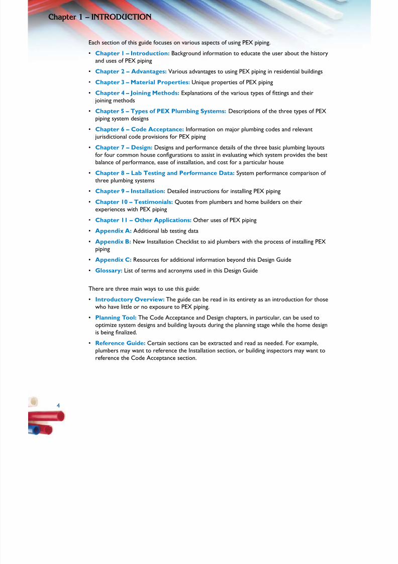
Each section of this guide focuses on various aspects of using PEX piping.
• Chapter 1 – Introduction: Background information to educate the user about the history
and uses of PEX piping
• Chapter 2 – Advantages: Various advantages to using PEX piping in residential buildings
•
Chapter 3 – Material Properties: Unique properties of PEX piping• Chapter 4 – Joining Methods: Explanations of the various types of ttings and their
joining methods
• Chapter 5 – Types of PEX Plumbing Systems: Descriptions of the three types of PEXpiping system designs
• Chapter 6 – Code Acceptance: Information on major plumbing codes and relevant jurisdictional code provisions for PEX piping
• Chapter 7 – Design: Designs and performance details of the three basic plumbing layouts
for four common house congurations to assist in evaluating which system provides the best
balance of performance, ease of installation, and cost for a particular house
• Chapter 8 – Lab Testing and Performance Data: System performance comparison of three plumbing systems
• Chapter 9 – Installation: Detailed instructions for installing PEX piping
• Chapter 10 – Testimonials: Quotes from plumbers and home builders on theirexperiences with PEX piping
• Chapter 11 – Other Applications: Other uses of PEX piping
• Appendix A: Additional lab testing data
• Appendix B: New Installation Checklist to aid plumbers with the process of installing PEXpiping
• Appendix C: Resources for additional information beyond this Design Guide
• Glossary: List of terms and acronyms used in this Design Guide
There are three main ways to use this guide:
• Introductory Overview: The guide can be read in its entirety as an introduction for thosewho have little or no exposure to PEX piping.
• Planning Tool: The Code Acceptance and Design chapters, in particular, can be used tooptimize system designs and building layouts during the planning stage while the home designis being nalized.
• Reference Guide: Certain sections can be extracted and read as needed. For example,plumbers may want to reference the Installation section, or building inspectors may want toreference the Code Acceptance section.
4
5/11/2018 Pex Design Guide - slidepdf.com
http://slidepdf.com/reader/full/pex-design-guide-55a0d1ab10986 15/128
5
AdVAnTAGES
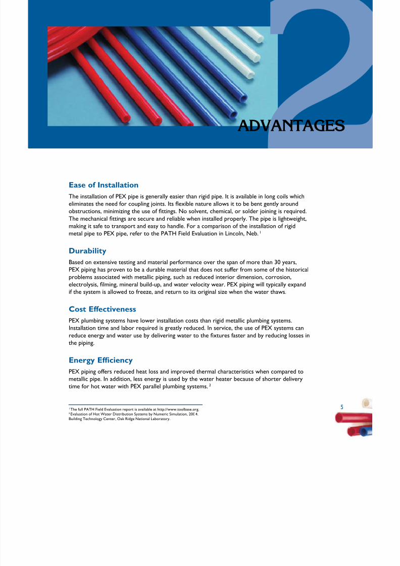
Ease of Installation
The installation of PEX pipe is generally easier than rigid pipe. It is available in long coils whicheliminates the need for coupling joints. Its exible nature allows it to be bent gently around
obstructions, minimizing the use of ttings. No solvent, chemical, or solder joining is required.
The mechanical ttings are secure and reliable when installed properly. The pipe is lightweight,
making it safe to transport and easy to handle. For a comparison of the installation of rigidmetal pipe to PEX pipe, refer to the PATH Field Evaluation in Lincoln, Neb.1
Durability
Based on extensive testing and material performance over the span of more than 30 years,PEX piping has proven to be a durable material that does not suffer from some of the historical
problems associated with metallic piping, such as reduced interior dimension, corrosion,electrolysis, lming, mineral build-up, and water velocity wear. PEX piping will typically expand
if the system is allowed to freeze, and return to its original size when the water thaws.
Cost Effectiveness
PEX plumbing systems have lower installation costs than rigid metallic plumbing systems.Installation time and labor required is greatly reduced. In service, the use of PEX systems canreduce energy and water use by delivering water to the xtures faster and by reducing losses in
the piping.
Energy Efciency
PEX piping offers reduced heat loss and improved thermal characteristics when compared tometallic pipe. In addition, less energy is used by the water heater because of shorter deliverytime for hot water with PEX parallel plumbing systems.2
1 The full PATH Field Evaluation report is available at http://www.toolbase.org.2 Evaluation of Hot Water Distribution Systems by Numeric Simulation, 2004.Building Technology Center, Oak Ridge National Laboratory.
5
5/11/2018 Pex Design Guide - slidepdf.com
http://slidepdf.com/reader/full/pex-design-guide-55a0d1ab10986 16/128
6
Chapte 2 – AdVAnTAGES
Noise Reduction
When properly secured, PEX piping can be signicantly quieter than rigid systems. It is
inherently less noisy due to its exibility and ability to absorb pressure surges.
Water Conservation
Properly designed PEX plumbing systems have the potential to conserve water (see Chapters 5and 7). The exibility of PEX allows it to bend around corners and run continuously, reducing
the need for ttings; this allows downsizing the pipe diameter to 3/8-inch for certain xtures.
Home-run systems and 3/8-inch pipes minimize the time it takes hot water to reach thexture. Lengthy delivery time for hot water represents a signicant waste of water as well as
energy; a problem exacerbated in larger homes.
In 2002, the NAHB Research Center conducted software simulations and laboratory tests ona “typical” hot water system using a trunk and branch rigid pipe design and one that included a3/8-inch diameter PEX home-run system. Results indicated that systems using shorter 3/8-inch
runs with a home-run manifold reduced the wait time for hot water and wasted less water than
longer runs of rigid pipe with many elbows and connections.3
Environmentally Sound
PEX is a modication or enhancement of high-density polyethylene, an economical and highly
cost-effective construction piping material. Generally, manufacturing equivalent lengths of plastic pipe consumes far less energy than manufacturing metallic pipe. The lighter weight of PEX compared to metallic piping helps to lower transportation costs and energy consumption,
offering even greater benet.
PEX pipes can be recycled as an inert ller material that can be incorporated into other
polymers for specic applications. There is also reduced water use through faster delivery time.
In addition, PEX pipe does not contain harmful VOCs.
3 Performance Comparison of Residential Hot Water Systems,November 2002, NAHB Research Center report available athttp://www.toolbase.org/.
6

5/11/2018 Pex Design Guide - slidepdf.com
http://slidepdf.com/reader/full/pex-design-guide-55a0d1ab10986 17/128
7
MATErIALProPErTIES
PEX is a material made up of molecules of high-density polyethylene (HDPE) that arepermanently linked to each other by a process called crosslinking. Crosslinking makes PEX a
“thermoset” polymer, which gives it long-term stability.
Polyethylene can be crosslinked using several technologies. All methods induce links betweenthe single strands of PE to form a dense network through radical reactions. The number
of links between the strands determines the crosslink density and is an important factor indetermining the physical properties of the material. The minimum percent crosslinking foreach method is specied in the ASTM F 876 standard. The three most common methods of
crosslinking polyethylene are as follows:
Peroxide – Peroxides are heat-activated chemicals that generate free radicals forcrosslinking. This is called the Engel Process.
Moisture-cured Vinylsilane – This method involves grafting a reactive silanemolecule to the backbone of the polyethylene. This is called the Silane Process.
Beta Irradiation – This method involves subjecting a dose of high-energy electrons
to the PE. This is called the Radiation Process.
In European standards these three methods are referred to as PEX-A, PEX-B, and PEX-C,respectively, and are not related to any type of rating system.
PEX pipe produced by any of the three methods must meet the same qualification requirementsas specified in the PEX standards. Although methods of crosslinking produce different
characteristics, all three methods have been utilized to manufacture approved PEX products.As required in any manufacturing process, procedures for each technology must be establishedand followed with good quality control checks in place to produce quality products.
7

5/11/2018 Pex Design Guide - slidepdf.com
http://slidepdf.com/reader/full/pex-design-guide-55a0d1ab10986 18/128
8
Chapte 3 – MATErIAL ProPErTIES
Temperature and Pressure
PEX piping meets all requirements for pressure and temperature performance in residentialapplications. Consensus standards published by the American Society for Testing and Materials(ASTM) International specify temperature and pressure-resistant capabilities of PEX pipe and
all tubing used in residential applications bears the appropriate test marking.
In the event of a water heating system malfunction, PEX piping is designed to accommodateshort-term conditions of 48 hours at 210ºF (99ºC) and 150 psi (1034 kPa) until repairs can
be made. The most commonly used safety relief valve (T&P) activates (opens) at either of these temperature or pressure conditions. All PEX piping has been tested to withstand T&Pactivation for 30 days to ensure that safety requirements are met. As such, PEX systems DONOT require the use of a special T&P valve.
ASTM F 876: Standard Specification for Cross-Linked Polyethylene (PEX) Tubing coversPEX piping that is outside diameter controlled, and pressure rated for water at threetemperatures—160 psi @ 73.4ºF, 100 psi @ 180ºF, and 80 psi @ 200ºF. Included are
requirements and test methods for material, workmanship, dimensions, hydrostatic sustainedpressure strength, burst pressure, oxidative (chlorine) resistance, and environmental stress
cracking.
ASTM F 877: Standard Specification for Cross-Linked Polyethylene (PEX) Plastic Hot- and Cold-Water Distribution Systems covers requirements and test methods for PEX hot- and cold-waterdistribution system components made in one standard dimension ratio, and intended for 100
psi water service, up to and including a maximum working temperature of 180ºF. Componentsare comprised of piping and ttings. Requirements and test methods are included for
hydrostatic sustained pressure strength, thermocycling resistance, ttings, and bend strength.
Flexibility
The exible nature of PEX allows it to be bent gently around obstructions and installed as one
continuous run without ttings. Slight changes in direction are made easily by bending the pipeby hand. There is a predetermined bend radius of a 90-degree change of direction withoutinstalling a tting (reference manufacturer’s installation instructions). Minimizing mechanical
connections can result in quicker installations, less potential for leaks at ttings, and less
resistance due to pressure drops through ttings.
Noise and Water Hammer Resistance
As water ows through pipes, pressure in the system gives moving water energy, known as
kinetic energy. Kinetic energy increases with the speed of water and also with the mass of
water that is owing. When the ow of water is stopped, such as when a valve or faucet is
closed, this kinetic energy must be dissipated in the system.
The ability of a plumbing pipe to dissipate energy due to surge in water pressure is based
on the pipe’s modulus of elasticity, a measure of material stiffness. A higher modulus of elasticity means the material is more rigid. Copper pipe is 180 times more rigid than PEX pipe.Ultimately, this means that with rigid piping systems, pressure surges can produce noticeable
banging sounds as energy is dissipated, thus causing what is known as “water hammer.” Thepressure surge that causes water hammer can produce instantaneous pressures of 300 to 400psi (2070 to 2760 kPa), which can cause damage to rigid pipes, ttings, and connections.

5/11/2018 Pex Design Guide - slidepdf.com
http://slidepdf.com/reader/full/pex-design-guide-55a0d1ab10986 19/128
9
Chapte 3 – MATErIAL ProPErTIE
The exibility of PEX pipe allows the pipe itself to absorb energy from pressure surges and
eliminate or reduce the occurrence of water hammer.
Resistance to Freeze Damage
PEX pipes are less susceptible to the effects of cold temperatures retaining their exibility even
below freezing. This exibility means that if water-lled PEX piping freezes, the elasticity of thematerial allows it to expand without cracking or splitting, and then to return to its original sizeupon thawing. This applies when PEX pipes have room to expand evenly along their length, as istypical when installed within walls or ceilings. PEX pipes inside a slab may not be able to expandevenly.
Chlorine Resistance
The U.S. Environmental Protection Agency (EPA) recommends that all drinking water be
disinfected, typically using free chlorine, chloramines, or other less common methods.Currently, the majority of potable drinking water in the United States and Canada is disinfectedusing free chlorine. For water treated with free chlorine, the EPA sets a maximum disinfectantlevel of 4.0 parts per million (ppm) within the water distribution system.
The second-most common disinfectant is chloramines. Research conducted by JanaLaboratories, at the request of the Plastics Pipe Institute (PPI), indicates that free chlorine isgenerally more aggressive to cross-linked polyethylene (PEX) pipes than chloramines.
To ensure the reliability of PEX piping systems in hot chlorinated water applications, it is arequirement of the PEX pipe product standard specication ASTM F 876 that all PEX pipes
intended for use with potable water have a minimum extrapolated lifetime of 50 years when
tested in accordance with test method ASTM F 2023: “Standard Test Method for Evaluating theOxidative Resistance of Cross-linked Polyethylene (PEX) Tubing and Systems to Hot Chlorinated
Water.” The minimum requirement applies to traditional domestic applications.4
The test conditions of ASTM F 2023 require that the test uid has a minimum oxidativereduction potential (ORP) of 825 mV. To produce test uid with this high ORP, third-party test
laboratories typically use reverse osmosis-puried water with a free chlorine concentration
of 4.3 +/- 0.3 ppm (4.3 mg/L) and pH of 6.8 +/- 0.2, resulting in an ORP of 825 mV or higher.This represents a very aggressive water quality, which gives conservative results. This testprocedure is designed to extrapolate the life expectancy of a hot-water plumbing pipe whenused at a water temperature of 140°F and a pressure of 80 psi. Continuous recirculation and
traditional domestic4 conditions can both be evaluated by ASTM F 2023.
PEX pipe manufacturers must have pipes tested and certied by NSF International, UL and/or
other third-party certication agencies to meet the requirements of ASTM F 876, including
chlorine resistance. In addition, manufacturers may have pipes certied to NSF International
protocol P 171: “Chlorine Resistance of Plastic Piping Materials.” PEX piping systems use ttingsthat also must comply with ASTM standards, and are made from brass, copper, or high-
temperature engineered polymers that are chlorine-resistant.
In summary, PEX pipe has shown itself to be resistant to attack from chlorine and chloraminesunder a wide range of conditions, and has performed reliably in all regions of North America.
94 Traditional domestic applications are dened in ASTM F 2023 as piping systems which operate for up
to 25 percent of the ser vice time at a water temperature of 140°F (60°C) and 75 percent of the timeat ambient room temperatures. A plumbing system with more demanding water qualit y conditionsthan those listed above should be discussed with the PEX piping manufacturer before installation.

5/11/2018 Pex Design Guide - slidepdf.com
http://slidepdf.com/reader/full/pex-design-guide-55a0d1ab10986 20/128
10
Chapte 3 – MATErIAL ProPErTIES
Corrosion Resistance
PEX pipe and ttings have been tested extensively with aggressive potable water conditions and
did not pit or corrode. PEX pipe and ttings are tested with corrosive pH levels between 6.5
and 6.7, much lower and more aggressive than levels found in common water systems.
A related aspect of corrosion in pipes is concerned with ow erosion. Flow erosion tests of
PEX ttings were conducted by the PPI High Temperature Division (HTD). See “Erosion Study on Brass Insert Fittings Used in PEX Piping Systems,” PPI-TN-26 for discussion and results.
Ultraviolet (UV) Resistance
Like most plastics, the long-term performance of PEX will be affected by UV radiation fromsunlight. Although most PEX pipes have some UV resistance, PEX pipes should not be stored
outdoors where they are exposed to the sun. Precautions must be taken once the pipe isremoved from the original container. Each PEX pipe manufacturer publishes a maximumrecommended UV exposure limit, based on the UV resistance of that pipe. Do not allow PEX
pipes to be over-exposed beyond these limits. PEX pipes should not be installed outdoors,
unless they are buried in earth or properly protected from UV exposure, either direct orindirect.
Indirect (diffused) and reected sunlight also have UV energy. If PEX will be exposed to
sunlight continuously after installation, such as in an unnished basement, cover the pipe with
a UV-blocking sleeve (black preferred) or approved pipe insulation. Different manufacturers’pipes have different degrees of UV resistance as indicated on their labels; always follow the
recommendations provided by the particular manufacturer.
See PPI “UV Labeling Guidelines for PEX Pipes,” TN-32.
Caution
• Do not store PEX pipes outdoors.
• Keep PEX pipes in original packaginguntil time of installation.
• Ensure that exposure to sunlightduring installation does not exceedthe maximum recommended UVexposure time as recommended by
the manufacturer.
10
5/11/2018 Pex Design Guide - slidepdf.com
http://slidepdf.com/reader/full/pex-design-guide-55a0d1ab10986 21/128
1
Chapte 3 – MATErIAL ProPErTIE
Inert Material – Safe for Drinking Water
Since PEX piping is used to transport potable water, it must comply with federal regulationsfor public safety. PEX materials are inert (not chemically reactive) and cannot contaminate thepotable water passing through them. The ttings are mechanical and do not require the use of
solvents or chemicals that might leach into the water when the system is rst used.
Testing and certication must comply with NSF/ANSI Standard 61: Drinking Water SystemComponents - Health Effects, and Standard 14: Plastic Pipe System Components and Related
Materials. The primary focus of Standard 61 is to establish minimum health effect requirementsfor chemical contaminants and impurities that are indirectly imparted into drinking waterfrom products, components, and materials used in potable water systems. PEX piping systemsare tested at water pH levels from 5.0 to 10.0, both excessive acidity and alkalinity, beyond
levels encountered in potable water systems. PEX pipe does not corrode, and it is resistantto mineral build-up. NSF/ANSI Standard 14 covers physical, performance, and health effectrequirements for plastic piping system components used in potable hot- and cold-water
distribution systems.
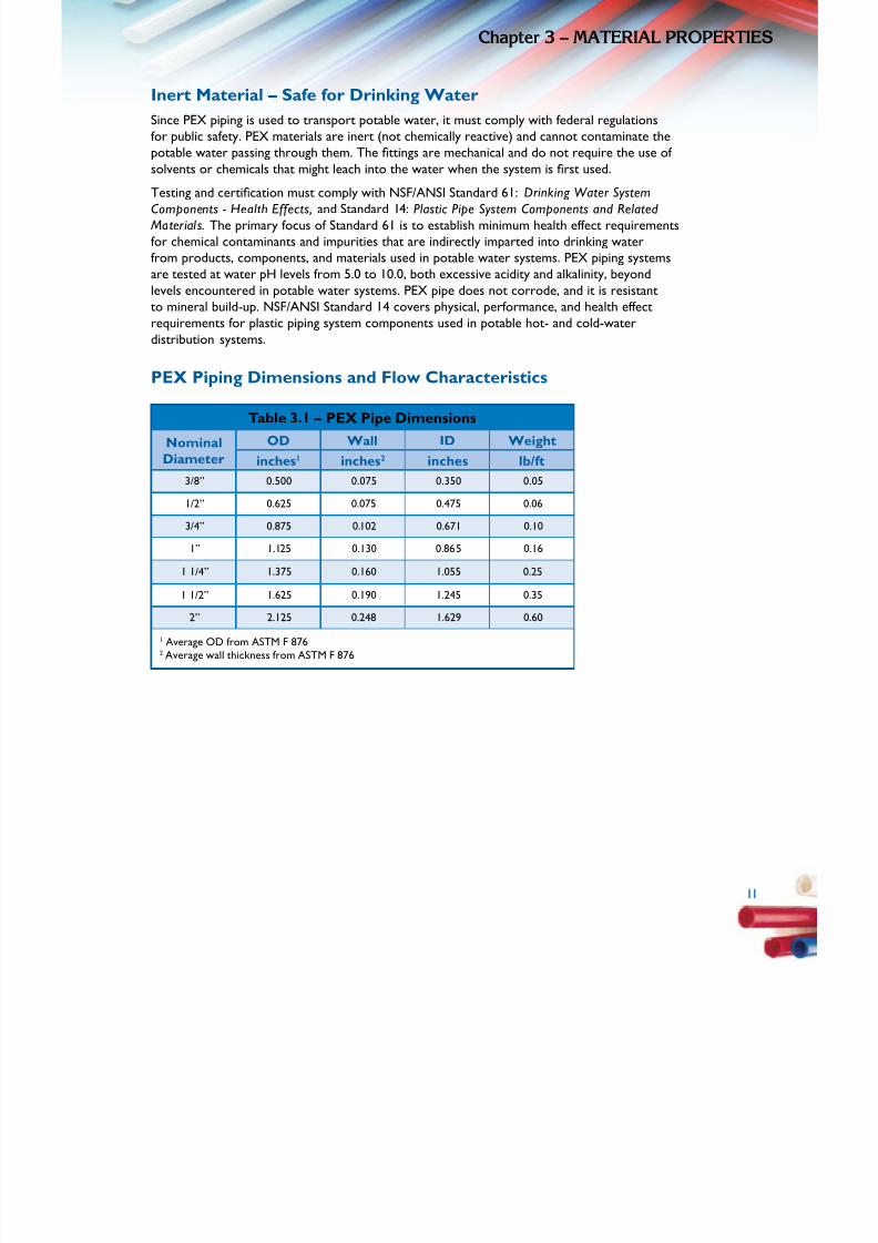
PEX Piping Dimensions and Flow Characteristics
Table 3.1 – PEX Pipe Dimensions
NominalDiameter
OD Wall ID Weight
inches1 inches2 inches lb/ft
3/8” 0.500 0.075 0.350 0.05
1/2” 0.625 0.075 0.475 0.06
3/4” 0.875 0.102 0.671 0.10
1” 1.125 0.130 0.865 0.16
1 1/4” 1.375 0.160 1.055 0.25
1 1/2” 1.625 0.190 1.245 0.35
2” 2.125 0.248 1.629 0.60
1 Average OD from ASTM F 8762 Average wall thickness from ASTM F 876
1

5/11/2018 Pex Design Guide - slidepdf.com
http://slidepdf.com/reader/full/pex-design-guide-55a0d1ab10986 22/128
12
Chapte 3 – MATErIAL ProPErTIES
Table 3.2 – Flow Velocity
Flow Rate ft/sec
GPM 3/8” 1/2” 5/8” 3/4” 1” 1 1/4” 1 1/2” 2”
0.2 0.67 0.36 0.25 0.18 0.11 0.07 0.05 0.03
0.3 1.00 0.54 0.37 0.27 0.16 0.11 0.08 0.05
0.4 1.33 0.72 0.50 0.36 0.22 0.15 0.11 0.06
0.5 1.67 0.91 0.62 0.45 0.27 0.18 0.13 0.08
0.6 2.00 1.09 0.74 0.54 0.33 0.22 0.16 0.09
0.7 2.33 1.27 0.87 0.64 0.38 0.26 0.18 0.11
0.8 2.67 1.45 0.99 0.73 0.44 0.29 0.21 0.12
0.9 3.00 1.63 1.12 0.82 0.49 0.33 0.24 0.14
1.0 3.33 1.81 1.24 0.91 0.55 0.37 0.26 0.15
1.1 3.67 1.99 1.36 1.00 0.60 0.40 0.29 0.17
1.2 4.00 2.17 1.49 1.09 0.66 0.44 0.32 0.18
1.3 4.34 2.35 1.61 1.18 0.71 0.48 0.34 0.20
1.4 4.67 2.53 1.74 1.27 0.76 0.51 0.37 0.22
1.5 5.00 2.72 1.86 1.36 0.82 0.55 0.40 0.23
1.6 5.34 2.90 1.98 1.45 0.87 0.59 0.42 0.25
1.7 5.67 3.08 2.11 1.54 0.93 0.62 0.45 0.26
1.8 6.00 3.26 2.23 1.63 0.98 0.66 0.47 0.28
1.9 6.34 3.44 2.36 1.72 1.04 0.70 0.50 0.29
2.0 6.67 3.62 2.48 1.81 1.09 0.73 0.53 0.31
2.5 8.34 4.53 3.10 2.27 1.36 0.92 0.66 0.38
3.0 10.00 5.43 3.72 2.72 1.64 1.10 0.79 0.46
3.5 11.67 6.34 4.34 3.18 1.91 1.28 0.92 0.54
4.0 7.24 4.96 3.63 2.18 1.47 1.05 0.62
4.5 8.15 5.58 4.08 2.46 1.65 1.19 0.69
5.0 9.05 6.20 4.54 2.73 1.84 1.32 0.77
6.0 10.86 7.44 5.44 3.28 2.20 1.58 0.92
7.0 8.68 6.35 3.82 2.57 1.84 1.08
8.0 9.92 7.26 4.37 2.94 2.11 1.23
9.0 11.16 8.17 4.91 3.30 2.37 1.39
12

5/11/2018 Pex Design Guide - slidepdf.com
http://slidepdf.com/reader/full/pex-design-guide-55a0d1ab10986 23/128
1
Chapte 3 – MATErIAL ProPErTIE
Table 3.2 – Flow Velocity (continued)
Flow Rate ft/sec
GPM 3/8” 1/2” 5/8” 3/4” 1” 1 1/4” 1 1/2” 2”
10.0 9.07 5.46 3.67 2.64 1.54
11.0 9.98 6.01 4.04 2.90 1.69
12.0 10.89 6.55 4.40 3.16 1.85
13.0 7.10 4.77 3.43 2.00
14.0 7.64 5.14 3.69 2.16
15.0 8.19 5.51 3.95 2.31
Table 3.3 – Pressure Loss
60°F (16°C) Water
Flow Rate Pressure Loss psi/100 ft of Pipe
GPM 3/8” 1/2” 5/8” 3/4” 1” 1 1/4” 1 1/2” 2”
0.2 0.427 0.099 0.040 0.019 0.006 0.002 0.001 0.0003
0.3 0.880 0.204 0.083 0.039 0.012 0.005 0.002 0.001
0.4 1.470 0.341 0.138 0.065 0.019 0.008 0.003 0.001
0.5 2.189 0.508 0.205 0.097 0.029 0.011 0.005 0.001
0.6 3.032 0.703 0.284 0.135 0.040 0.015 0.007 0.002
0.7 3.993 0.926 0.374 0.177 0.053 0.020 0.009 0.003
0.8 5.069 1.175 0.475 0.225 0.067 0.026 0.012 0.003
0.9 6.258 1.450 0.586 0.278 0.082 0.032 0.014 0.004
1.0 7.555 1.751 0.707 0.335 0.099 0.038 0.017 0.005
1.1 8.960 2.076 0.839 0.397 0.118 0.046 0.021 0.006
1.2 10.47 2.425 0.980 0.464 0.138 0.053 0.024 0.007
1.3 12.08 2.799 1.131 0.535 0.159 0.061 0.028 0.008
1.4 13.80 3.195 1.291 0.611 0.181 0.070 0.032 0.009
1.5 15.61 3.615 1.460 0.691 0.205 0.079 0.036 0.010
1.6 17.52 4.058 1.639 0.776 0.230 0.089 0.040 0.011
1.7 19.53 4.523 1.827 0.865 0.256 0.099 0.045 0.012
1.8 21.64 5.010 2.023 0.958 0.284 0.110 0.050 0.014
1

5/11/2018 Pex Design Guide - slidepdf.com
http://slidepdf.com/reader/full/pex-design-guide-55a0d1ab10986 24/128
14
Chapte 3 – MATErIAL ProPErTIES
Table 3.3 – Pressure Loss (continued)
60°F (16°C) Water
Flow Rate Pressure Loss psi/100 ft of Pipe
GPM 3/8” 1/2” 5/8” 3/4” 1” 1 1/4” 1 1/2” 2”
1.9 23.84 5.519 2.229 1.055 0.313 0.121 0.055 0.015
2.0 26.14 6.050 2.443 1.157 0.343 0.133 0.060 0.017
2.5 39.00 9.024 3.643 1.724 0.511 0.197 0.089 0.025
3.0 54.10 12.51 5.050 2.390 0.708 0.274 0.124 0.034
3.5 71.36 16.50 6.658 3.150 0.933 0.360 0.163 0.045
4.0 20.97 8.459 4.002 1.185 0.458 0.207 0.057
4.5 25.90 10.45 4.943 1.463 0.565 0.256 0.071
5.0 31.30 12.63 5.972 1.768 0.683 0.309 0.085
6.0 43.44 17.52 8.284 2.451 0.946 0.428 0.118
7.0 23.11 10.93 3.232 1.248 0.564 0.156
8.0 29.38 13.89 4.108 1.585 0.717 0.198
9.0 36.32 17.17 5.076 1.959 0.885 0.244
10.0 20.75 6.134 2.367 1.070 0.295
11.0 24.63 7.281 2.808 1.269 0.350
12.0 28.81 8.514 3.284 1.484 0.409
13.0 9.832 3.792 1.713 0.472
14.0 11.24 4.332 1.957 0.539
15.0 12.72 4.905 2.216 0.610
Shown is pressure loss in units of psi per 100 feet of pipe.
14
5/11/2018 Pex Design Guide - slidepdf.com
http://slidepdf.com/reader/full/pex-design-guide-55a0d1ab10986 25/128
1
CodEACCEPTAnCE
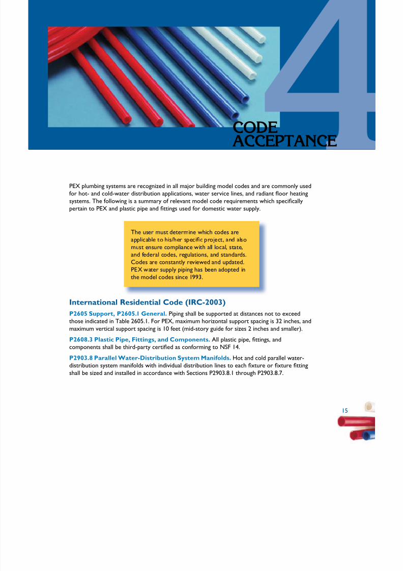
PEX plumbing systems are recognized in all major building model codes and are commonly usedfor hot- and cold-water distribution applications, water service lines, and radiant oor heating
systems. The following is a summary of relevant model code requirements which specically
pertain to PEX and plastic pipe and ttings used for domestic water supply.
i ili l is/ i l
li i l ll i
l ily pipi
i
The user must determ ne wh ch codes areapp cab e to h her spec c project, and a so
must ensure comp ance w th a l loca , state,and federal codes, regu at ons, and standards.Codes are constant y rev ewed and updated.PEX water supp ng has been adopted in
the model codes s nce 1993.
International Residential Code (IRC-2003)
P2605 Support, P2605.1 General. Piping shall be supported at distances not to exceedthose indicated in Table 2605.1. For PEX, maximum horizontal support spacing is 32 inches, and
maximum vertical support spacing is 10 feet (mid-story guide for sizes 2 inches and smaller).
P2608.3 Plastic Pipe, Fittings, and Components. All plastic pipe, ttings, and
components shall be third-party certied as conforming to NSF 14.
P2903.8 Parallel Water-Distribution System Manifolds. Hot and cold parallel water-distribution system manifolds with individual distribution lines to each xture or xture tting
shall be sized and installed in accordance with Sections P2903.8.1 through P2903.8.7.
1
5/11/2018 Pex Design Guide - slidepdf.com
http://slidepdf.com/reader/full/pex-design-guide-55a0d1ab10986 26/128
16
Chapte 4 – CodE ACCEPTAnCE
P2903.8.1 Sizing of Manifolds. Manifolds shall be sized in accordance with Table P2903.8.1.A maximum gallon per minute (gpm) is specied for different nominal inside diameter sizes for
plastic and metallic manifolds.
P2903.8.3 Maximum Length. The maximum length of individual distribution lines shall be60 feet (18.2 m) nominal.
P2903.8.5 Support and Protection. Plastic piping bundles shall be secured in accordancewith manufacturer’s installation instructions and supported in accordance Section P2605.Bundles that have a change in direction equal to or greater than 45 degrees shall be protected
from chafng at the point of contact with framing members by sleeving or wrapping.
P2904.5 Water Distribution Pipe. References Table P2904.5. PEX plastic tubing shallconform to ASTM F 877 and CSA B137.5 standards.
P2904.9.1.4 Cross-linked Polyethylene Plastic (PEX). References Section P2904.9.1.4.1or Section P2904.1.4.2.
P2904.9.1.4.2 Mechanical Joints. Mechanical joints shall be installed in accordance withmanufacturer’s instructions. Fittings for PEX plastic tubing as described in ASTM F 1807, ASTM
F 1960, ASTM F 2080, and ASTM F 2159, shall be installed in accordance with manufacturer’sinstructions.
P2904.16.2 Plastic Pipe or Tubing to Other Pipe Materials. Joints between differentgrades of plastic pipe or between plastic pipe and other piping material shall be made with anapproved adapter tting.
International Plumbing Code (IPC 2003)
605.3 Water Service Pipe. Water service pipe shall conform to NSF61 and shall conform to
one of the standards listed in Table 605.3 (ASTM F 876, ATM F 877, and CSA-B137.5).
605.4 Water Distribution Pipe. Water distribution pipe shall conform to NSF 61 and shall
conform to one of the standards listed in Table 605.4 (ASTM F 877, and CSA-B137.5).
605.5 Fittings. Pipe ttings shall be approved for installation with the piping material installed
and shall conform to one of the standards listed in Table 605.5 (ASTM F 1807, ASTM F 1960,and ASTM F 2080).
605.17 Cross-linked Polyethylene Plastic. Joints between cross-linked polyethylene plastictubing or ttings shall comply with Sections 605.17.1 and 605.17.2.
605.17.3 Mechanical Joints. Mechanical joints shall be installed in accordance withmanufacturer’s instructions. Fittings for PEX tubing as described in ASTM F 1807, ASTM F1960, and ASTM F 2080 shall be installed in accordance with manufacturer’s instructions
605.23.2 Plastic Pipe or Tubing to Other Piping Material. Joints between differentgrades of plastic pipe or between plastic pipe and other piping material shall be made with anapproved adapter tting.
16
5/11/2018 Pex Design Guide - slidepdf.com
http://slidepdf.com/reader/full/pex-design-guide-55a0d1ab10986 27/128
1
Chapte 4 – CodE ACCEPTAnC
National Standard Plumbing Code (NSPC 2003)
3.4.1. Plastic Piping. Plastic piping materials used for the conveyance of potable water shallcomply with NSF 14 and be marked accordingly.
3.4.2. Water Service Piping. Water service piping to the point of entrance into the building
shall be of materials listed in Table 3.4, and shall be water pressure rated for not less than 160
psig at 73°F. Table 3.4: PEX Plastic Water Distribution Systems (ASTM F 877 with ASTM F1807, F 1960, or F 2098 Fittings)
3.4.3. Water Distribution Piping. Water piping for distribution of hot and cold waterwithin buildings shall be of materials listed in Table 3.4, and shall be water pressure rated fornot less than 100 psig at 180°F. Plastic piping used for hot water distribution shall be installed in
accordance with requirements of Section 10.15.8. NOTE: The working pressure rating for certainapproved plastic piping materials varies depending on pipe size, pipe schedule, and methods of
joining.
10.15.8 Plastic Piping. Plastic piping used for hot-water distribution shall conform to therequirements of Section 3.4 and Table 3.4. Piping shall be water pressure rated for not less
than 100 psi at 180°F. NOTE: The working pressure rating for certain approved plastic piping materials varies depending on pipe size, pipe schedule, and methods of joining. Plastic pipe
or tube shall not be used downstream from instantaneous water heaters, immersion waterheaters or other heaters not having approved temperature safety devices. Piping within 6inches of ue or vent connectors shall be approved metallic pipe or tube. Normal operating
pressure in water distribution piping systems utilizing approved plastic pipe or tube for hot-water distribution shall not be more than 80 psi.
Uniform Plumbing Code (UPC-2003)
604.11 PEX. Cross-linked polyethylene (PEX) tubing shall be marked with the appropriatestandard designation(s) (see Chapter 9) for which the tubing has been approved. PEX tubing
shall be installed in compliance with the provisions of this section.
604.11.1 PEX Fittings. Metal insert ttings, metal compression ttings, and cold expansion
ttings used with PEX tubing shall be manufactured to and marked in accordance with the
standards for the ttings (see Chapter 9).
604.11.2 Water Heater Connections. PEX shall not be installed within the rst 18 inches
(457 mm) of piping connected to a water heater.
International Code Council (ICC)Evaluation Service Reports (ESR) and Evaluation Reports (ER)International Code Council-Evaluation Service (ICC-ES) conducts technical evaluations of building products, components, methods, and materials. The evaluation process culminateswith issuance of technical reports that, because they directly address code compliance, are
useful to both regulatory agencies and building-product manufacturers. Agencies use evaluationreports to determine code compliance and enforce building regulations; manufacturers use
1

5/11/2018 Pex Design Guide - slidepdf.com
http://slidepdf.com/reader/full/pex-design-guide-55a0d1ab10986 28/128
18
Chapte 4 – CodE ACCEPTAnCE
reports as evidence that their products meet code requirements and warrant regulatoryapproval. Several PEX manufacturers have ESRs or ERs. Evaluation Reports can be obtained
from www.icc-es.org.
International Association of Plumbing and Mechanical Ofcials
(IAPMO) Guide CriteriaThe IAPMO Guide Criteria (IGC) procedure provides manufacturers and product developersan opportunity to draft IAPMO standards as a vehicle for introducing new products, when
no applicable standard exists for the product. Once an IGC is accepted, IAPMO can listproducts manufactured in compliance with the new requirements. Some PEX and PEX tting
manufacturers have products listed under IGCs. Lists of IGCs can be obtained from
www.iapmo.org.
C904-06 American Waterworks Association (ANSI/AWWA
C904-06)
This standard describes PEX pressure pipe made from material having a standard PEX materialdesignation code of PEX 1006 in ASTM F 876 for use as underground water service lines in
sizes 1/2 inch through 3 inches, and conform to a standard dimension ration of SDR9.
Included in this standard are criteria for classifying PEX plastic pipe materials and a system of nomenclature, requirements, and test methods for materials and pipe. Methods of marking are
given. Design, installation, and application considerations are discussed in the forward of thisstandard.
18

5/11/2018 Pex Design Guide - slidepdf.com
http://slidepdf.com/reader/full/pex-design-guide-55a0d1ab10986 29/128
1
JoInInGMETHodS
There are several types of joining methods or ttings used with PEX plumbing systems. All are
mechanical ttings that are either directional or transitional. PEX piping cannot be joined by
solvent cementing. Most PEX piping manufacturers have their own mechanical tting system. The method of connection should comply
with the manufacturer’s recommendations and instructions.Fittings are regulated to comply with performance andmaterial criteria from recognized standards. They shouldbe marked by a certied third-party agency such as NSF,
IAPMO, CSA, IGC, UL or other third-party testing and listingagency.
l i li le
wi l i lle
Not a l tt ngs are app cab
th a l PEX p pe. Consu t yourmanufacturer for acceptabmethods.
The most common types of tting systems used are Cold Expansion Fittings and Metal or
Plastic Insert Fittings. Other types of ttings are available but are less common.
19
5/11/2018 Pex Design Guide - slidepdf.com
http://slidepdf.com/reader/full/pex-design-guide-55a0d1ab10986 30/128
20
Chapte 5 – JoInInG METHodS
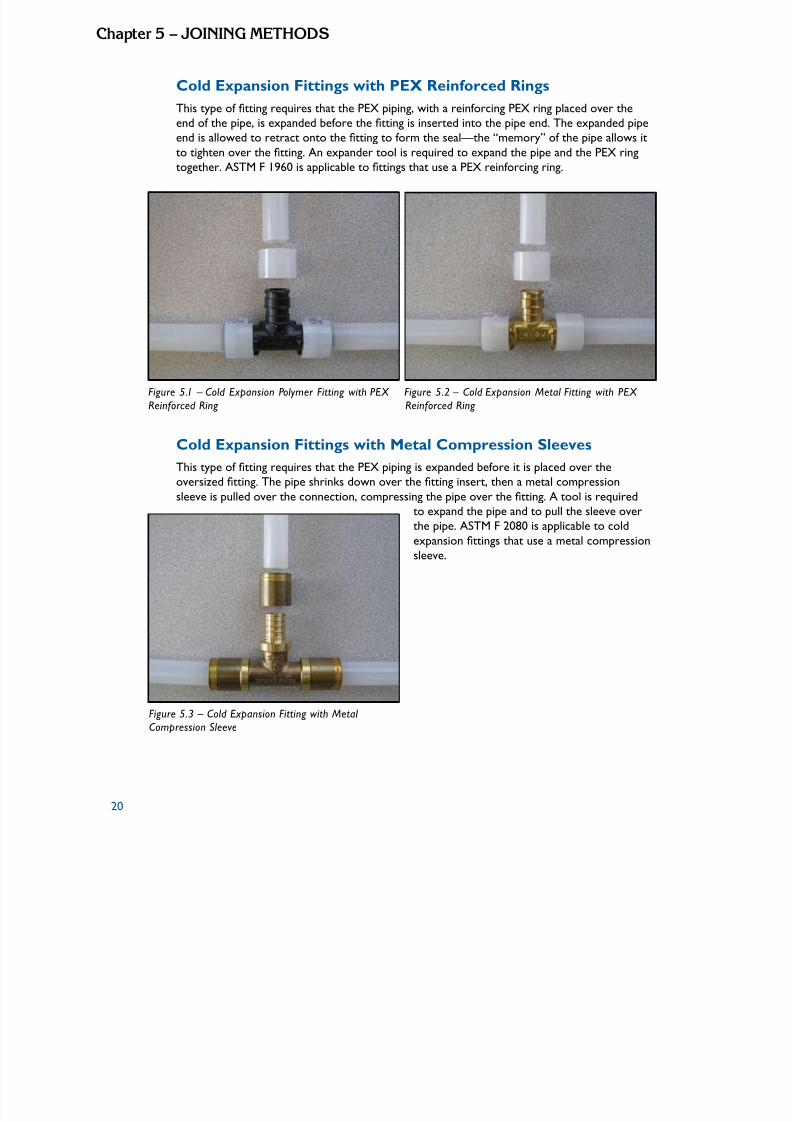
Cold Expansion Fittings with PEX Reinforced Rings
This type of tting requires that the PEX piping, with a reinforcing PEX ring placed over the
end of the pipe, is expanded before the tting is inserted into the pipe end. The expanded pipe
end is allowed to retract onto the tting to form the seal—the “memory” of the pipe allows it
to tighten over the tting. An expander tool is required to expand the pipe and the PEX ring
together. ASTM F 1960 is applicable to ttings that use a PEX reinforcing ring.
Figure 5.1 – Cold Expansion Polymer Fitting with PEX Figure 5.2 – Cold Expansion Metal Fitting with PEX
Reinforced Ring Reinforced Ring
Cold Expansion Fittings with Metal Compression Sleeves
This type of tting requires that the PEX piping is expanded before it is placed over the
oversized tting. The pipe shrinks down over the tting insert, then a metal compression
sleeve is pulled over the connection, compressing the pipe over the tting. A tool is required
to expand the pipe and to pull the sleeve overthe pipe. ASTM F 2080 is applicable to coldexpansion ttings that use a metal compression
sleeve.
Figure 5.3 – Cold Expansion Fitting with Metal Compression Sleeve
5/11/2018 Pex Design Guide - slidepdf.com
http://slidepdf.com/reader/full/pex-design-guide-55a0d1ab10986 31/128
2
Chapte 5 – JoInInG METHod
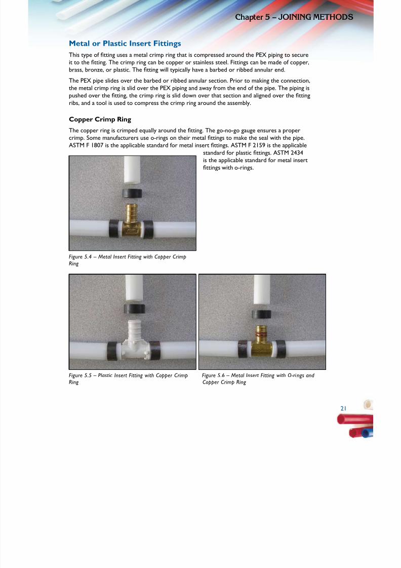
Metal or Plastic Insert Fittings
This type of tting uses a metal crimp ring that is compressed around the PEX piping to secure
it to the tting. The crimp ring can be copper or stainless steel. Fittings can be made of copper,
brass, bronze, or plastic. The tting will typically have a barbed or ribbed annular end.
The PEX pipe slides over the barbed or ribbed annular section. Prior to making the connection,
the metal crimp ring is slid over the PEX piping and away from the end of the pipe. The piping ispushed over the tting, the crimp ring is slid down over that section and aligned over the tting
ribs, and a tool is used to compress the crimp ring around the assembly.
Copper Crimp Ring
The copper ring is crimped equally around the tting. The go-no-go gauge ensures a proper
crimp. Some manufacturers use o-rings on their metal ttings to make the seal with the pipe.
ASTM F 1807 is the applicable standard for metal insert ttings. ASTM F 2159 is the applicable
standard for plastic ttings. ASTM 2434
is the applicable standard for metal insertttings with o-rings.
Figure 5.4 – Metal Insert Fitting with Copper CrimpRing
Figure 5.5 – Plastic Insert Fitting with Copper Crimp Figure 5.6 – Metal Insert Fitting with O-rings and Ring Copper Crimp Ring
2

5/11/2018 Pex Design Guide - slidepdf.com
http://slidepdf.com/reader/full/pex-design-guide-55a0d1ab10986 32/128
22
Chapte 5 – JoInInG METHodS
Stainless Steel Clamp
The stainless steel ring is crimped using a ratcheting tool, which only releases once a propercrimp is achieved. ASTM 2098 is the applicable standard for stainless steel insert rings.
Figure 5.7 – Metal Insert Fitting with Stainless Steel Figure 5.8 – Metal Insert Fitting with Stainless Steel
Clamp Band Clamp Sleeve
Stainless Steel Sleeve
This type of tting is made of metal and uses a press sleeve or cap to secure the PEX pipe to
the tting. These ttings have ribbed annular ends that are inserted into the PEX pipe. A sleeve
or cap slides over the outer part of the piping and the tting is inserted into the pipe. The pipe
must be fully inserted. A press tool is used to make the nal connection. It is important that
the appropriate tool is used per manufacturer’sinstructions. This type of tting is often used in
other industries to make pneumatic or hydraulichose line connections.
Figure 5.9 – Metal Insert Fitting with Stainless Steel Press Sleeve

5/11/2018 Pex Design Guide - slidepdf.com
http://slidepdf.com/reader/full/pex-design-guide-55a0d1ab10986 33/128
2
Chapte 5 – JoInInG METHod
Push Type Fittings
This type of tting uses an interlocking mechanism to connect the PEX pipe to the tting.
The pipe is inserted, or pushed, into the tting, and locked into place with a fastening device
that keeps the pipe from being backed-out or disconnected. This type of tting is sometimes
referred to as a “quick connect” tting. Push type ttings typically use some type of o-ring
or gasket to form a seal around the PEXpipe. A support liner is inserted intothe pipe, and a fastening system with a
locking component, such as a snap ringor twist collar, is used to ensure thatthe connection remains permanent.ASSE 1061 and IAPMO – IGC 188 are
the applicable standards for push typettings. Not all ttings of this type are
permitted to be installed in inaccessible
locations or underground. Verify withyour manufacturer and local codes before
installation.
Figure 5.10 – Push Type Fitting
2

5/11/2018 Pex Design Guide - slidepdf.com
http://slidepdf.com/reader/full/pex-design-guide-55a0d1ab10986 34/128
24
Chapte 5 – JoInInG METHodS
Standard Specications for Fittings
Fittings are categorized in accordance with ASTM or IAPMO specications, as follows:
ASTM F 1807: Standard Specication for Metal Insert Fittings Utilizing a Copper
Crimp Ring for SDR9 Cross-Linked Polyethylene (PEX) Tubing
This specication covers metal insert ttings and copper crimp rings for use with PEX tubing
that meet requirements in ASTM F 876 and F 877. These ttings are intended for use in 100
psi (690 kPa) cold- and hot-water distribution systems operating at temperatures up to andincluding 180ºF (82ºC). Requirements for materials, workmanship, dimensions, and markings tobe used on ttings and rings are also included. Size range is 3/8 to 1 1/4 inches.
ASTM F 1960: Standard Specication for Cold Expansion Fittings with PEX
Reinforcing Rings for Use with Cross-Linked Polyethylene (PEX) Tubing
This specication covers cold expansion ttings and PEX reinforcing rings for use with PEX
plastic tubing that meet requirements of ASTM F 876 and F 877. These ttings are intended for
use in 100 psi (690 kPa) cold- and hot-water distribution systems operating at temperaturesup to and including 180ºF (82ºC). The system is comprised of a PEX reinforcing ring and acold expansion tting. Included are requirements for materials, workmanship, dimensions, and
markings to be used on tting components. Size range is 3/8 to 1 1/2 inches.
ASTM F 2080: Standard Specication for Cold Expansion Fittings with Metal
Compression Sleeves for use with PEX Pipe
This specication covers cold-expansion ttings using metal compression sleeves for use with
PEX plastic pipe that meet requirements of ASTM F 876 and F 877, whereby the PEX pipe iscold-expanded before tting assembly. These cold expansion ttings and metal compression
sleeves are intended for use in residential and commercial, hot and cold, potable waterdistribution systems, with continuous operation at pressures up to and including 100 psi (690kPa), and at temperatures up to and including 180ºF (82ºC). Included in the specication are
requirements for materials, workmanship, dimensions, and markings to be used on ttings and
compression sleeves. Performance requirements are as referenced in ASTM F 877. Size range is3/8 to 2 inches.
ASTM F 2098: Standard Specication for Stainless Steel Clamps for Securing SDR9
Cross-Linked Polyethylene (PEX) Tubing to Metal Insert Fittings
This specication covers stainless steel clamps for use with four sizes of insert ttings that
comply with F 1807, and cross-linked polyethylene (PEX) plastic tubing that complies withF 876 or F 877. These clamps are intended as an alternative to the copper-alloy crimp-
rings of Specications F 1807 or F 2159 for use in 100 psi (689.5 kPa) cold- and hot-waterdistribution systems operating at temperatures up to and including 180ºF (82ºC). Includedare requirements for materials, workmanship, dimensions, and marking of the stainless steelclamps; requirements for deforming the clamps, which apply to assemblies of PEX tubing
and Specications F 1807 and F 2159, insert ttings secured with deformed clamps per this
specication.
24
5/11/2018 Pex Design Guide - slidepdf.com
http://slidepdf.com/reader/full/pex-design-guide-55a0d1ab10986 35/128
2
Chapte 5 – JoInInG METHod
ASTM F 2159: Standard Specication for Plastic Insert Fittings Utilizing a Copper
Crimp Ring for SDR9 Cross-Linked Polyethylene (PEX) Tubing
This specication covers plastic insert ttings and copper crimp rings for use with PEX pipe
that meets requirements in ASTM F 876 and F 877. It establishes requirements for sulfoneplastic insert ttings and copper crimp rings for PEX plastic tubing. These ttings are intended
for use in 100 psi (690 kPa) cold- and hot-water distribution systems operating at temperaturesup to and including 180ºF (82ºC). Included are requirements for material, molded partproperties, performance, workmanship, dimensions, and markings to be used on ttings and
rings. Size range is 3/8 to 1 inch.
ASTM F 2434: Standard Specication for Metal Insert Fittings Utilizing a Copper
Crimp Ring for SDR9 PEX Tubing and SDR9 PEX-AL-PEX Tubing
This specication covers metal insert ttings with o-ring seals and copper crimp rings for use
with cross-linked polyethylene (PEX) tubing in 1/2, 3/4, 1, and 1 1/4 inch nominal diameters
that meet the requirements for Specications F 876 and F 877. These ttings are intended for
use in 100 psi (689.5 kPa) cold- and hot-water distribution systems operating at temperatures
up to and including 180ºF (82ºC). Included are the requirements for materials, workmanship,dimensions, performance, and markings to be used on the ttings and rings. Size range is 1/2 to
1 1/2 inches.
IAPMO – IGC 188: Removable and Non-Removable Push Fit Fittings
This specication covers removable and non-removable push t ttings for use with PEX pipe
that meet requirements in ASTM F 876 and F 877. The purpose of this standard is to establisha generally acceptable standard for ttings with a quick assembly push-t mechanism that are
used with various types of outside diameter controlled tubing. The ttings range in size from
3/8 to 2 inches. This standard covers minimum requirements for materials of construction andprescribes minimum performance requirements for tting joints and marking and identication
requirements.
ASSE Standard – 1061
This standard applies to push-t ttings that can be used with one or more of the following
materials:
1. PEX tubing complying with ASTM F 876 or ASTM F 877;
2. Type K, L and M copper tubing complying with ASTM B 88; and
3. CPVC tubing complying with ASTM D 2846.
Push-t ttings may be designed to be used with one or more types of tubing that conform to
the dimensions as specied in their respective standard. This standard serves to supplementASTM F 877, ASTM D 2846 and ASTM B 88 in describing a test method for a specic type of
push-t tting system to be used with PEX, Copper, and/or CPVC tubing. This standard covers
minimum tting joints, marking, and identication.
2

5/11/2018 Pex Design Guide - slidepdf.com
http://slidepdf.com/reader/full/pex-design-guide-55a0d1ab10986 36/128
26
Chapte 5 – JoInInG METHodS
26

5/11/2018 Pex Design Guide - slidepdf.com
http://slidepdf.com/reader/full/pex-design-guide-55a0d1ab10986 37/128
2
TYPES oF PEXPLuMBInG SYSTEM
The unique properties of PEX piping allow it to be congured in a number of different
residential plumbing system designs. This section describes three layout options: trunk and
branch, home-run, and remote manifold. By carefully choosing the right system for theapplication, the plumbing designer can produce a home that balances cost, installation time, andperformance.
27

5/11/2018 Pex Design Guide - slidepdf.com
http://slidepdf.com/reader/full/pex-design-guide-55a0d1ab10986 38/128
28
Chapte 6 – TYPES oF PEX PLuMBInG SYSTEMS
Trunk and Branch
For decades, trunk and branch (T&B) piping systems have been used by plumbers for potablewater distribution using rigid plastic or metal pipe. Installation of PEX piping can be performedin a similar manner using a main trunk line to supply various branch take-offs to specic outlets.
Typically the trunk line services numerous outlets while the branch line services generally one
to three closely grouped outlets, such as in a bathroom. Installation of PEX piping in the T&Bdesign follows the general design requirements established in plumbing codes.
As with rigid piping systems, use of tee and elbow ttings allows for the connection of branch
take-offs from the main trunk. However, given the fact that PEX is available in long coils, theuse of coupling ttings can be reduced or eliminated. Unlike rigid pipe systems, many elbow
ttings can be eliminated in favor of sweep turns of the piping.
Specic features and
advantages of the PEX trunk and branch design include:
• Simple system design
conversion from rigidpiping to exible PEX
piping
• Opportunities to reduce
the number of ttings
installed
• T&B systems will deliver
hot water quicker duringsequential ows
• T&B systems will generally
supply one xture at a
higher pressure
Figure 6.1 – PEX Pipes in a Trunk and Branch System Design
28

5/11/2018 Pex Design Guide - slidepdf.com
http://slidepdf.com/reader/full/pex-design-guide-55a0d1ab10986 39/128
2
Chapte 6 – TYPES oF PEX PLuMBInG SYSTEM
Home-Run
The unique features of PEX piping make it ideal for use in manifold-type system designs,commonly referred to as home-run plumbing systems. In this design, all xtures are fed from
dedicated piping that runs directly and unbroken from central manifolds. The hot watermanifold should be located in close proximity to the hot water source to ensure fast and
efcient delivery.
All outlets are individually fed from a common manifold or two central manifolds (hot andcold). Because inline ttings are eliminated, pressure losses along the line are reduced, allowing
the piping size to be reduced for certain xtures. Three-eighths-inch piping may be used for
lower ow applications and 1/2-inch piping is recommended for higher ow applications.
The home-run system often has more evenly distributed pressure losses when owing water
to xtures since all lines are fed from a common point, rather than adding multiple xtures into
the same pipe section. Smaller diameter pipe also results in quicker delivery of hot water fromthe water heater, although each line must be purged independently.
If the manifold is installed using valved outlets, many plumbing codes do not require a secondvalve at the xture, speeding installation and adding convenience much like an electrical breaker
panel.
Specic features and
advantages of the PEXhome-run design include:
• Easier piping runs toeach xture using smaller
diameter piping
• Opportunity to eliminateall ttings between the
manifold and the outlet
• Opportunity to have
centrally located individualshut-offs housed at the
manifold
• Quicker delivery of hot
and cold water to theoutlets
• A more stable pressure
to each xture when
operating simultaneousxtures
Figure 6.2 – PEX Pipes in a Home-Run Design
2

5/11/2018 Pex Design Guide - slidepdf.com
http://slidepdf.com/reader/full/pex-design-guide-55a0d1ab10986 40/128
30
Remote Manifold
A third method for installing PEX piping combines elements of the rst two systems and is
typically referred to as a remote manifold system design. The basic approach to this systemis running hot and cold trunk lines to some convenient location in close proximity to multiple
xtures, such as for a bathroom group. At this point a smaller remote manifold is installed on
each trunk line. The remote manifolds can be ow-through or closed end. Individual branchlines are then run to each xture in the same manner as the central manifold. Manifolds with
valves must be installed in accessible locations; manifolds without valves may be installed in
enclosed spaces.
The remote manifold system performs in a similar manner to the T&B system. However, itsimplies the installation due to the reduced number of ttings that are required.
Specic features and
advantages of the PEXremote manifold design
include:
•
Relatively simple systemdesign conversion from
rigid piping to exible PEX
piping
• Opportunities to reduce
the number of ttings
installed
• Quicker hot waterdelivery during sequentialows
• Opportunity to havecentrally located individualshut-offs housed at theremote manifold
Figure 6.3 – PEX Pipes in a Remote Manifold Design
30
5/11/2018 Pex Design Guide - slidepdf.com
http://slidepdf.com/reader/full/pex-design-guide-55a0d1ab10986 41/128
3
dESIGn
The unique features of PEX piping allow for a great deal of system design freedom that canincrease the performance and savings associated with the plumbing system. In today’s high-
performance homes, many designers recognize that the plumbing system can be designed toprovide hot or cold water faster with much less energy loss. PEX plumbing systems can bedesigned to enhance these features but, like any plumbing system, PEX piping systems performbest and cost less to install when planned during the home’s design phase. Advanced planning
allows maximum performance, while limiting the lengths of pipe and number of ttings used.
And, when considered early enough in the house planning stage, a few simple room layoutconsiderations can greatly improve the performance of the plumbing system. By consulting thecodes and local inspectors in advance, builders and plumbers can also avoid costly time delays
due to code issues arising during construction.
This chapter describes a process that provides the guidance and tools needed to successfully
layout a PEX piping system in nearly any home. Four major areas of the design process arehighlighted:
• Consult Local Codes
• Optimize Home Layout
• Select Piping System Type
• Plan Piping Routing, Manifold, and Valve Locations
Consult Local Codes
If PEX piping has not been used before, or is still uncommon in your local area, it is helpful toreview the local codes for use of PEX piping. As discussed in the Chapter 4 of this document,PEX piping is approved for use in all model codes. Local amendments may restrict or change
3

5/11/2018 Pex Design Guide - slidepdf.com
http://slidepdf.com/reader/full/pex-design-guide-55a0d1ab10986 42/128
32
Chapte 7 – dESIGn
the way PEX may be used for certain applications. For that reason, it is important to consultlocal codes to determine specic requirements before beginning a new piping design.
It may also be helpful to consult with local building inspectors to notify them in advancethat you plan to use PEX piping for your project. They can be helpful in pointing out localrequirements and amendments. Alerting the inspector of your intent to use a new technology
in advance can help to avoid delays that often occur when an unfamiliar material is encounteredon the jobsite. This design manual may be useful as a reference guide for an inspector who isunfamiliar with PEX.
In the event that questions arise regarding the application, performance, or code acceptance of PEX, both the Plastics Pipe Institute (PPI) and the Plastic Pipe and Fittings Association (PPFA)can provide support. Each organization can provide technical and training materials to aid codeofcials and plumbers.
Optimize Home Designs
Ironically, some of the most substantial problems with modern plumbing system designs
relate not to the piping itself, but to the design and layout of the house. The materials that arechosen for framing, the location of rooms, the location of the water heater(s), and the pointat which the water main enters the home all have a substantial impact on the performance of a plumbing system. Often, the design of the plumbing system is left until the end of the design
process when the home layout is largely determined. This often results in a poorly performingand excessively costly system. By observing a number of guidelines early in the home designprocess, PEX piping can be installed in a way that minimizes costs, eases installation, andincreases homeowner satisfaction.
The key to optimizing home designs for PEX plumbing is to minimize pipe lengths from thewater main and water heater. While this may seem intuitive, it cannot be stressed enough.Short piping runs result in shorter wait times for hot water, fewer ttings, faster installation
time, and lower material costs. This can be accomplished by the builder or designer in the earlyplanning stage using several basic design principles.
1. Group xtures together – Grouping plumbing xtures around a common location can
result in saving time, materials, hot water energy, and water. This can be done betweenoors as well, such as in the case of stacked bathrooms. Where possible, avoid locating
bathrooms long distances from the water heater.
2. Centrally locate distribution point – Centrally located water heaters and incomingwater supplies can signicantly improve the performance of a plumbing system. Often water
heaters are arbitrarily located for convenience or placed in the utility room as far from
the living space as possible. This approach often leads to exceedingly long plumbing runsalong with the resultant increase in materials, installation time, and water and energy use.
Whenever feasible, locate the water main and heater as close as possible to the mid-point of the xture groupings to keep piping runs short.
3. Create spaces for bundled pipe runs – Particularly applicable to home-run PEXplumbing runs where few ttings are installed, simultaneous installation of multiple piping
runs will reduce installation time. The exibility of PEX piping and the long, unbroken lengths
that can be easily spooled enable the simultaneous installation of multiple plumbing lines
32
5/11/2018 Pex Design Guide - slidepdf.com
http://slidepdf.com/reader/full/pex-design-guide-55a0d1ab10986 43/128
3
Chapte 7 – dESIG
running in the same direction using common holes and chases. By creating space in softs
and chases for piping bundles, installation time can be reduced. However, cold and hot water
lines should be bundled separately.
4. Use building elements that ease piping installation – Using building elements such asopen web oor trusses in some locations can dramatically speed up the process of installing
plumbing piping. This can also speed up the process of installation of other mechanicalsincluding ducting and wiring.
Select Piping System Design
The next step for the designer, plumber, and builder is to select the most appropriate plumbingsystem design for the home. The unique properties of PEX piping allow it to be congured in a
number of different designs. All have been shown to work well in residential applications, andall are code approved. Depending on the design of the home, each has different performance
characteristics, installation costs, material costs, and ease of installation. The selection of asystem design is generally based on a combination of key factors such as material cost, labortime, ease of installation, system performance, and installer preference.
The challenge for a plumbing designer is to select the system that balances the unique needs of the installer, homeowner, and builder. The purpose of this chapter is to provide a comparisonof the three most prevalent PEX plumbing systems, trunk and branch, home-run, and remote
manifold, and the guidance to select between system types.
Selecting among the three systems described is not cut and dry, and often involves a balanceof the key factors since each project, installer, and circumstance is different. Fortunately, there
is no wrong choice. All three system designs will supply sufcient ow and pressure to the
outlets even when the base riser pressure is 40 psi and the length to the farthest outlet is 100feet. But, the costs and performance of each system do vary for each house design. Selectingthe best system for your project can reduce installation costs, minimize installation headaches,
and lead to more satised homeowners.
To aid in the decision-making process, several tools are provided.
1. General Rankings of the Systems for Key Factors – This general comparison willprovide a place to start and compare how the systems stack up based on your priorities.
2. Example Layouts – Detailed layouts of each system are provided for four common housetypes. By selecting the type that most closely resembles your project, you can see how thesystems compare for your building design.
3. Performance Testing – The three systems were compared and tested in comprehensivelaboratory tests. By examining the test data you can identify differences in the systems’performance in varying scenarios.
4. Industry Technical Support – Manufacturers and organizations offer a range of resourcesto assist PEX users. The support ranges from general information to technical assistance onspecic projects.
3
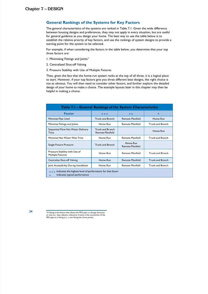
5/11/2018 Pex Design Guide - slidepdf.com
http://slidepdf.com/reader/full/pex-design-guide-55a0d1ab10986 44/128
34
Chapte 7 – dESIGn
General Rankings of the Systems for Key Factors
The general characteristics of the systems are ranked in Table 7.1. Given the wide differencebetween housing designs and preferences, they may not apply in every situation, but are usefulfor general guidance as you design your home. The best way to use the table below is to
establish the relative priority of key factors, and use the rankings of system designs to provide a
starting point for the system to be selected.For example, if when considering the factors in the table below, you determine that your top
three factors are:
1. Minimizing Fittings and Joints5
2. Centralized Shut-off Valving
3. Pressure Stability with Use of Multiple Fixtures
Then, given the fact that the home-run system ranks at the top of all three, it is a logical placeto start. However, if your top factors give you three different best designs, the right choice isnot as obvious. You will then need to consider other factors, and further explore the detailed
design of your home to make a choice. The example layouts later in this chapter may then behelpful in making a choice.
Table 7.1 – General Rankings of the System Characteristics
Factor * * * * * *
Minimize Pipe Used Trunk and Branch Remote Manifold Home-Run
Minimize Fittings and Joints Home-Run Remote Manifold Trunk and Branch
Sequential Flow Hot Water Delivery
Time
Trunk and Branch
Remote Manifold
Home-Run
Minimize Hot Water Wait Time Home-Run Remote Manifold Trunk and Branch
Single Fixture Pressure Trunk and BranchHome-Run
Remote Manifold
Pressure Stability with Use of
Multiple FixturesHome-Run Remote Manifold Trunk and Branch
Centralize Shut-off Valving Home-Run Remote Manifold Trunk and Branch
Joint Accessibility During Installation Home-Run Remote Manifold Trunk and Branch
* * * Indicates the highest level of performance for that factor
* Indicates typical performance
5 A tting is the device that allows the PEX pipe to change direction
or size (i.e., tees, elbows, reducers). A joint is the connection of thePEX pipe to a tting (i.e. , a tee tting has t hree joints).
34
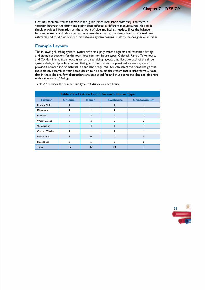
5/11/2018 Pex Design Guide - slidepdf.com
http://slidepdf.com/reader/full/pex-design-guide-55a0d1ab10986 45/128
3
Chapte 7 – dESIG
Cost has been omitted as a factor in this guide. Since local labor costs vary, and there isvariation between the tting and piping costs offered by different manufacturers, this guide
simply provides information on the amount of pipe and ttings needed. Since the balance
between material and labor cost varies across the country, the determination of actual costestimates and total cost comparison between system designs is left to the designer or installer.
Example Layouts
The following plumbing system layouts provide supply water diagrams and estimated ttings
and piping descriptions for the four most common house types: Colonial, Ranch, Townhouse,and Condominium. Each house type has three piping layouts that illustrate each of the three
system designs. Piping lengths, and tting and joint counts are provided for each system to
provide a comparison of material use and labor required. You can select the home design thatmost closely resembles your home design to help select the system that is right for you. Note
that in these designs, few obstructions are accounted for and thus represent idealized pipe runswith a minimum of ttings.Table 7.2 outlines the number and type of xtures for each house.
Table 7.2 – Fixture Count for each House Type
Fixture Colonial Ranch Townhouse Condominium
Kitchen Sink 1 1 1 1
Dishwasher 1 1 1 1
Lavatory 4 3 2 3
Water Closet 3 2 2 2
Shower/Tub 3 3 1 3
Clothes Washer 1 1 1 1
Utility Sink 1 0 0 0
Hose Bibbs 2 2 2 0
Total 16 13 10 11
3

5/11/2018 Pex Design Guide - slidepdf.com
http://slidepdf.com/reader/full/pex-design-guide-55a0d1ab10986 46/128
36
Chapte 7 – dESIGn
Colonial Layout
The Colonial house layout has approximately 2,000 square feet of oor area. The water main
enters the house under the unnished basement slab. The water heater is located near the
main water line in the basement. The rst oor has a living room, dining room, kitchen, family
room, and a powder room. The second oor has four bedrooms, two full baths, and the
clothes washer.
Table 7.3 – Fixture Summaryfor the Colonial House
Level
K i t c h e n
S i n k
D i s h w a s h e r
L a v a t o r y
W a t e r
C l o s e t
S h o w e r / T u b
C l o t h e s
W a s h e r
U t i l i t y S i n k
H o s e B i b b
T o t a l
Basement 0 0 0 0 0 0 1 0 1
First Floor 1 1 1 1 0 0 0 2 6
SecondFloor
0 0 3 2 3 1 0 0 9
Total 1 1 4 3 3 1 1 2 16
Table 7.4 – Material Summary for the Colonial House
System
Length of ColdPipe
Length of HotPipe
Fittings Manifolds Joints
1” 3/4” 1/2” 1” 3/4” 1/2” Tees Elbows Main Remote Fixtures Piping
Trunk and
Branch27’ 80’ 110’ 0’ 80’ 98’ 25 10 0 0 26 97
Home-Run
33’ 12’ 602’ 0’ 12’ 428’ 2 7 2 0 26 49
RemoteManifold
27’ 93’ 152’ 0’ 93’ 107’ 8 13 0 7 26 83
In larger homes with a large separation between bathrooms, the trunk and branch design usesthe least amount of total pipe but the most ttings and joints. The home-run system uses the
most piping (2.4 times on average) and the least amount of ttings and joints. While the home-
run system uses more piping, the piping has a smaller diameter which is easier to handle andinstall, particularly around bends. An appropriate balance between labor and material costs aswell as the relative performance of the systems is important when deciding on a system layoutfor your particular house.
36
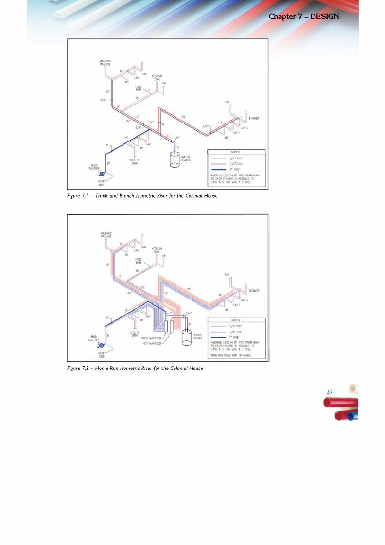
5/11/2018 Pex Design Guide - slidepdf.com
http://slidepdf.com/reader/full/pex-design-guide-55a0d1ab10986 47/128
3
Chapte 7 – dESIG
Figure 7.1 – Trunk and Branch Isometric Riser for the Colonial House
Figure 7.2 – Home-Run Isometric Riser for the Colonial House
3
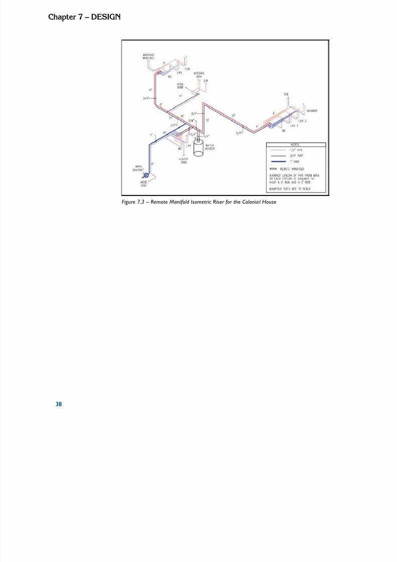
5/11/2018 Pex Design Guide - slidepdf.com
http://slidepdf.com/reader/full/pex-design-guide-55a0d1ab10986 48/128
38
Chapte 7 – dESIGn
Figure 7.3 – Remote Manifold Isometric Riser for the Colonial House
38

5/11/2018 Pex Design Guide - slidepdf.com
http://slidepdf.com/reader/full/pex-design-guide-55a0d1ab10986 49/128
3
Chapte 7 – dESIG
Ranch Layout
The Ranch house has approximately 1,300 square feet of one-story oor area. The water main
enters the house under the slab on grade. The one-story oor plan includes a great room,
a kitchen, a dining room, three bedrooms, and two full baths. The water heater and clothes
washer are located in the utility room.
Table 7.5 – Fixture Summaryfor the Ranch House
Level
K i t c h e n
S i n k
D i s h w a s h e r
L a v a t o r y
W a t e r
C l o s e t
S h o w e r / T u b
C l o t h e s
W a s h e r
U t i l i t y S i n k
H o s e B i b b
T o t a l
Main Floor 1 1 3 2 3 1 0 2 13
Table 7.6 – Material Summary for the Ranch House
System
Length of ColdPipe
Length of HotPipe
Fittings Manifolds Joints
1” 3/4” 1/2” 1” 3/4” 1/2” Tees Elbows Main Remote Fixtures Piping
Trunk and
Branch25’ 75’ 112’ 0’ 72’ 81’ 20 5 0 0 21 71
Home-Run
25’ 10’ 413’ 0’ 10’ 294’ 2 5 2 0 21 39
RemoteManifold
25’ 59’ 196’ 0’ 59’ 159’ 8 4 0 4 21 53
In home layouts with a large separation between xtures, the trunk and branch design uses the
least amount of pipe followed by the remote manifold design. The home-run system uses the
most piping (1.8 times more on average) and the least amount of ttings and joints. The home-
run system uses more piping, but with smaller diameters, which is easier to handle and install,particularly around bends. An appropriate balance between labor and material costs as well
as the relative performance of the systems is important when deciding on a system layout foryour particular house.
3
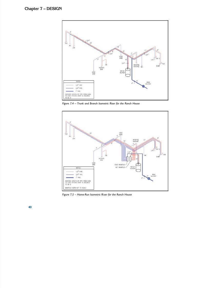
5/11/2018 Pex Design Guide - slidepdf.com
http://slidepdf.com/reader/full/pex-design-guide-55a0d1ab10986 50/128
40
Chapte 7 – dESIGn
Figure 7.4 – Trunk and Branch Isometric Riser for the Ranch House
Figure 7.5 – Home-Run Isometric Riser for the Ranch House
40
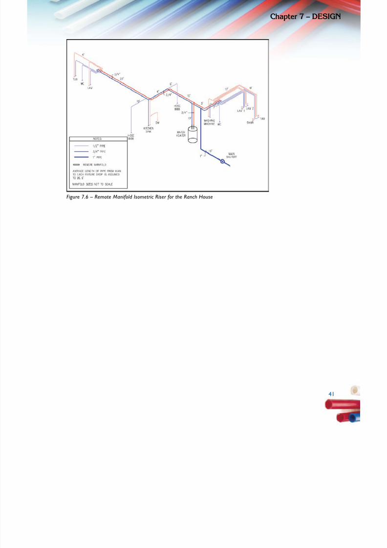
5/11/2018 Pex Design Guide - slidepdf.com
http://slidepdf.com/reader/full/pex-design-guide-55a0d1ab10986 51/128
4
Chapte 7 – dESIG
Figure 7.6 – Remote Manifold Isometric Riser for the Ranch House
4
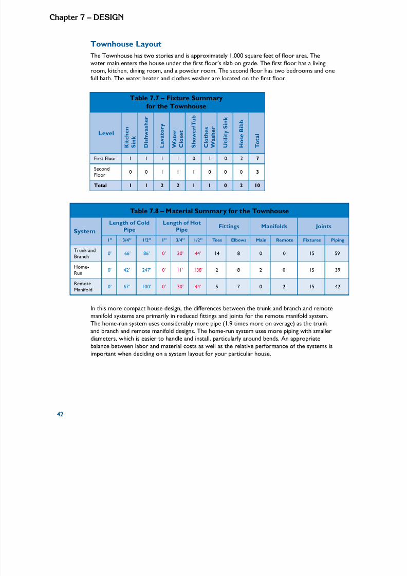
5/11/2018 Pex Design Guide - slidepdf.com
http://slidepdf.com/reader/full/pex-design-guide-55a0d1ab10986 52/128
42
Chapte 7 – dESIGn
Townhouse Layout
The Townhouse has two stories and is approximately 1,000 square feet of oor area. The
water main enters the house under the rst oor’s slab on grade. The rst oor has a living
room, kitchen, dining room, and a powder room. The second oor has two bedrooms and one
full bath. The water heater and clothes washer are located on the rst oor.
Table 7.7 – Fixture Summaryfor the Townhouse
Level
K i t c h e n
S i n k
D i s h w a s h e r
L a v a t o r y
W a t e r
C l o s e t
S h o w e r / T u b
C l o t h e s
W a s h e r
U t i l i t y S i n k
H o s e B i b b
T o t a l
First Floor 1 1 1 1 0 1 0 2 7
Second
Floor 0 0 1 1 1 0 0 0 3
Total 1 1 2 2 1 1 0 2 10
Table 7.8 – Material Summary for the Townhouse
System
Length of Cold
Pipe
Length of Hot
PipeFittings Manifolds Joints
1” 3/4” 1/2” 1” 3/4” 1/2” Tees Elbows Main Remote Fixtures Piping
Trunk and
Branch0’ 66’ 86’ 0’ 30’ 44’ 14 8 0 0 15 59
Home-
Run0’ 42’ 247’ 0’ 11’ 138’ 2 8 2 0 15 39
Remote
Manifold0’ 67’ 100’ 0’ 30’ 44’ 5 7 0 2 15 42
In this more compact house design, the differences between the trunk and branch and remotemanifold systems are primarily in reduced ttings and joints for the remote manifold system.
The home-run system uses considerably more pipe (1.9 times more on average) as the trunk and branch and remote manifold designs. The home-run system uses more piping with smallerdiameters, which is easier to handle and install, particularly around bends. An appropriate
balance between labor and material costs as well as the relative performance of the systems isimportant when deciding on a system layout for your particular house.
42
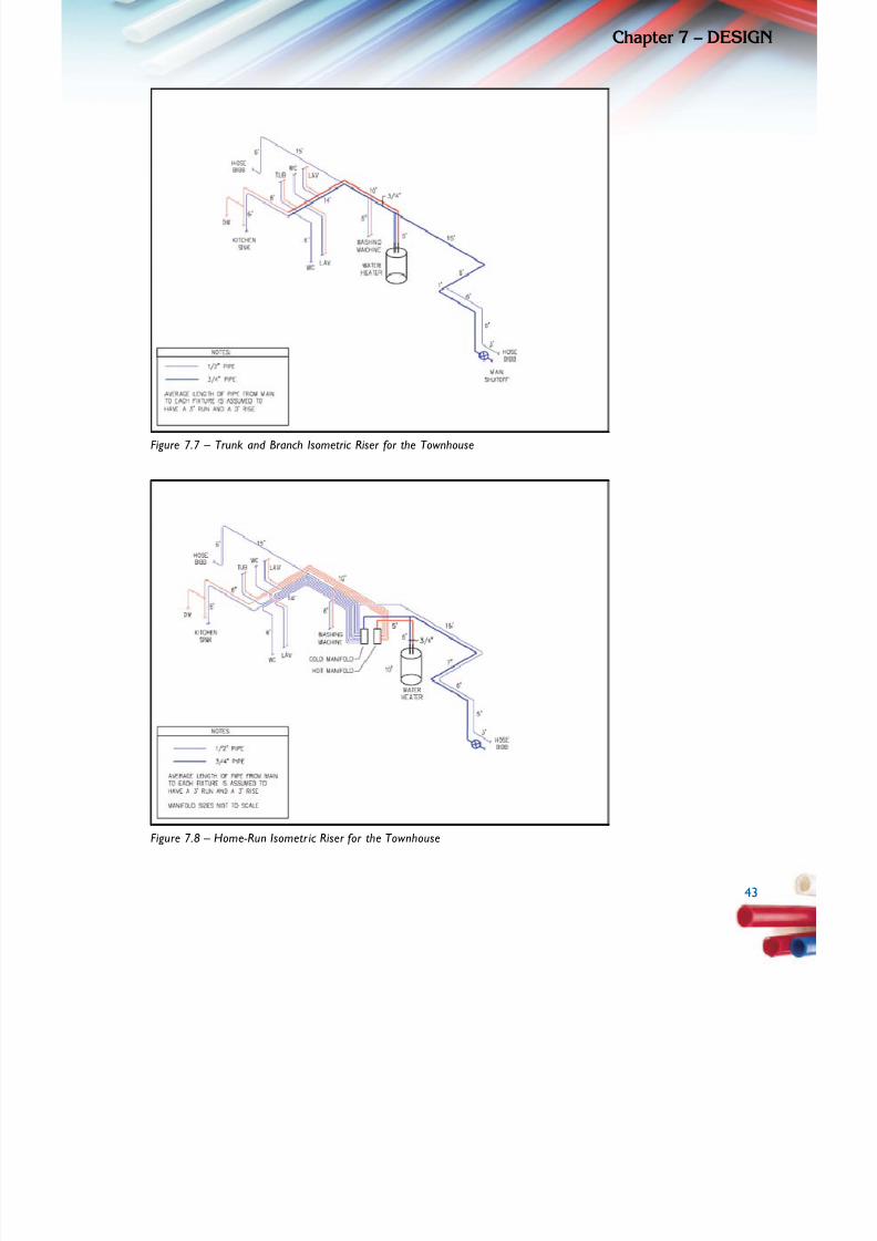
5/11/2018 Pex Design Guide - slidepdf.com
http://slidepdf.com/reader/full/pex-design-guide-55a0d1ab10986 53/128
4
Chapte 7 – dESIG
Figure 7.7 – Trunk and Branch Isometric Riser for the Townhouse
Figure 7.8 – Home-Run Isometric Ri ser for the Townhouse
4
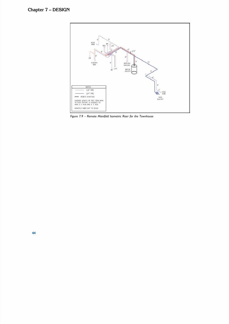
5/11/2018 Pex Design Guide - slidepdf.com
http://slidepdf.com/reader/full/pex-design-guide-55a0d1ab10986 54/128
44
Chapte 7 – dESIGn
Figure 7.9 – Remote Manifold I sometric Ri ser for the Townhouse
44

5/11/2018 Pex Design Guide - slidepdf.com
http://slidepdf.com/reader/full/pex-design-guide-55a0d1ab10986 55/128
4
Chapte 7 – dESIG
Condominium Layout
The Condominium has approximately 1,200 square feet of oor area. It has a living room,
kitchen, dining room, two bedrooms, and two full baths. The clothes washer is located in theunit. The condominium building has a central plant for water heating; therefore, there is no
water heater located in the unit.
Table 7.9 – Fixture Summary
for the Condominium
Level
K i t c h e n
S i n k
D i s h w a s h e r
L a v a t o r y
W a t e r
C l o s e t
S h o w e r / T u b
C l o t h e s
W a s h e r
U t i l i t y S i n k
H o s e B i b b
T o t a l
Main Floor 1 1 3 2 3 1 0 0 11
Table 7.10 – Material Summary for the Condominium
System
Length of ColdPipe
Length of HotPipe
Fittings Manifolds Joints
1” 3/4” 1/2” 1” 3/4” 1/2” Tees Elbows Main Remote Fixtures Piping
Trunk and
Branch0’ 45’ 120’ 0’ 45’ 104’ 17 0 0 0 19 53
Home-
Run0’ 10’ 295’ 0’ 10’ 242’ 1 2 2 0 19 29
Remote
Manifold0’ 35’ 132’ 0’ 35’ 115’ 5 0 0 4 19 37
The trunk and branch system uses the most tees which increases the number of joints. Thetrunk and branch and remote manifold system layouts are similar in pipe use, but the remotemanifold uses fewer ttings resulting in fewer joints. The home-run system uses the most pipe
(1.8 times more on average) and the least amount of ttings. The home-run system uses more
pipe with smaller diameters, which is easier to handle and install, particularly around bends. Anappropriate balance between labor and material costs as well as the relative performance of
the systems is important when deciding on a system layout for your particular house.
4

5/11/2018 Pex Design Guide - slidepdf.com
http://slidepdf.com/reader/full/pex-design-guide-55a0d1ab10986 56/128
46
Chapte 7 – dESIGn
Figure 7.10 – Trunk and Branch Isometric Riser for the Condominium
Figure 7.11 – Home-Run Isometric R iser for the Condominium
46
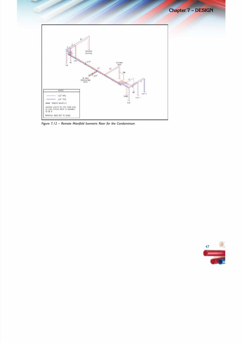
5/11/2018 Pex Design Guide - slidepdf.com
http://slidepdf.com/reader/full/pex-design-guide-55a0d1ab10986 57/128
4
Chapte 7 – dESIG
Figure 7.12 – Remote Manifold I sometric R iser for the Condominium
4
5/11/2018 Pex Design Guide - slidepdf.com
http://slidepdf.com/reader/full/pex-design-guide-55a0d1ab10986 58/128
48
Chapte 7 – dESIGn
Performance Verication Laboratory Testing
A set of laboratory tests using typical plumbing xtures and plumbing pipe sizes, runs and
ttings was performed to demonstrate the ow characteristics of the three different PEX
systems. Results of this testing indicate that all three systems will supply adequate pressure
and water delivery to a remote shower xture located 100 feet from the base riser with an
elevation head of 15 feet. Base source pressures of 40, 60, and 80 psi were used in each of the different system designs. Multiple tests were performed to add simultaneous ows from
other xtures including a shower, lavatory, kitchen and water closet. Test results are shown in
Chapter 8.
Industry Technical Support
If you have questions that have not been answered in this Design Guide, you can contact the
PEX manufacturer directly. The following websites provide a wealth of general information onPEX piping.
Plastics Pipe Institute
www.plasticpipe.orgPlastic Pipe and Fittings Association
www.ppfahome.org
ToolBase.orgwww.toolbase.org
Manufacturers of PEX piping and ttings can also provide specic technical assistance during
the design, planning, and installation phases. Contact information for each can be found at thePPI and PPFA and websites and on the individual manufacturers’ sites.
Plan Pipe Routing, Manifold, and Valve Locations
Once the system design is selected, the nal step in the design process is to plan pipe routing,
manifold, and valve locations. As in the case of the home design optimization, there are several
guidelines that can simplify this process. Bear in mind that PEX piping is available in continuouscoils as well as 20-foot straight lengths. Consult the local codes for specic installation
requirements for your project. Guidelines for optimizing the design of a PEX plumbing system include: 1. Minimize ttings – The exibility of PEX piping enables it to be easily installed around
obstructions and through framing members. Use of sweep turns (i.e., bending the pipe ina gentle sweep rather than using solid ttings) to change direction can result in quicker
installations, fewer mechanical ttings, and less resistance due to pressure drops common
through ttings.2. Group xtures together – If using trunk and branch or remote manifold, use common
trunk lines to feed multiple xture groups. For example, if two bathrooms are stacked, use a
single remote manifold to feed both, rather than two remote manifolds.
48

5/11/2018 Pex Design Guide - slidepdf.com
http://slidepdf.com/reader/full/pex-design-guide-55a0d1ab10986 59/128
4
Chapte 7 – dESIG
3. Minimize pipe lengths – Though this may seem intuitive, attention to this detail shouldlead to efciently installed plumbing systems, especially when considering plumbing layouts
using PEX piping.
4. Select appropriate pipe diameter – Many plumbing systems are installed using standardpractices that apply to very large homes but are excessive for smaller homes. Taking a
short amount of time to plan the piping sizes needed to supply the proper ow rates at therequired pressure, will result in the use of pipe sizes that deliver the required xture ow
rate, but are not oversized. Oversized plumbing system designs result in wasted energy andwater, as well as reduce customer satisfaction with the plumbing system.
5. Bundle pipe runs – Applicable particularly to PEX plumbing runs where few ttings are
installed, installation of multiple piping runs at the same time will reduce installation time.The exibility of PEX piping and the long unbroken lengths that can be easily spooled to
enable the simultaneous installation of multiple plumbing lines running in the same directionusing common holes through barriers such as joists.
6. Plan for solid attachment of transition points – The exibility of PEX piping also
requires that the transition to threaded ttings or rigid piping be performed correctly.
As with most piping materials, solid connection points and solid attachment points arenecessary when threading on valves and transition ttings to other materials.
7. Use color coding – PEX is available in different colors. Using dedicated colors for hot,cold, and greywater, where applicable, can be helpful for installers, homeowners, and futureretrots.
Before locating manifolds, determine whether valves will be placed at xtures or on manifolds.
Some jurisdictions require valves at the xture, while others allow them to be located on
central manifolds. In some cases the homeowner may express a preference for the location
of shut-off valves. If valves are to be placed on manifolds, they must be situated to allow easyaccess. This can be accomplished by placing them behind access panels, or open in basements,laundry rooms, mechanical rooms, or garages where no freeze potential exists. It is alsoimportant to label each valve on the manifold to ensure easy identication of the distribution
lines. If valves are not placed on the manifolds, and local codes allow, the manifolds may beenclosed within walls or oors, similar to any other tting such as a tee or ell.
4

5/11/2018 Pex Design Guide - slidepdf.com
http://slidepdf.com/reader/full/pex-design-guide-55a0d1ab10986 60/128
50
Chapte 7 – dESIGn
50

5/11/2018 Pex Design Guide - slidepdf.com
http://slidepdf.com/reader/full/pex-design-guide-55a0d1ab10986 61/128
5
PErForMAnCdATA
System Performance Comparison
Each of the three PEX plumbing congurations described in this guide can be installed in most
homes with satisfactory performance. The different systems offer opportunities to optimizethe performance of the plumbing system, reduce the installed cost, and increase overall
customer satisfaction and acceptance. In order to quantify the differences between PEX systemdesigns, each system was tested in the laboratory to provide a similar set of conditions underwhich the systems are installed and operated. Actual residential plumbing xtures, piping
layouts with ttings, and even elevation changes were installed and operated. This provided
a consistent comparison between system designs, as well as an indication of the minimum
performance characteristics of each system.PEX piping was installed in each of the three congurations—trunk and branch, home-run, and
remote manifold—with overall results showing:
• All systems had similar ow characteristics at each of the xtures when owing
independently
• All system designs responded in a similar manner to simultaneous ow events (more than
one xture owing at once)
• Minor differences in the actual measured ow and pressure at a test xture emerged when
simultaneous ow events occurred
Test System Design and Set-up
A set of plumbing xtures were installed in a laboratory setting to provide actual ow and
pressure data during operation of the xtures. These data provide assurance that the PEX
plumbing system design is capable of supplying the required ow rates during operation of the
xture. In addition, the test results provide assurance that the plumbing system design will
5
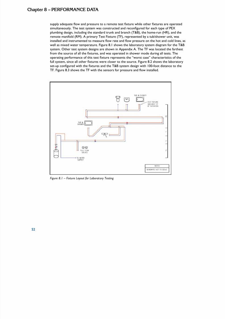
5/11/2018 Pex Design Guide - slidepdf.com
http://slidepdf.com/reader/full/pex-design-guide-55a0d1ab10986 62/128
52
Chapte 8 – PErForMAnCE dATA
supply adequate ow and pressure to a remote test xture while other xtures are operated
simultaneously. The test system was constructed and recongured for each type of PEX
plumbing design, including the standard trunk and branch (T&B), the home-run (HR), and theremote manifold (RM). A primary Test Fixture (TF), represented by a tub/shower unit, wasinstalled and instrumented to measure ow rate and ow pressure on the hot and cold lines, as
well as mixed water temperature. Figure 8.1 shows the laboratory system diagram for the T&B
system. Other test system designs are shown in Appendix A. The TF was located the farthestfrom the source of all the xtures, and was operated in shower mode during all tests. The
operating performance of this test xture represents the “worst case” characteristics of the
full system, since all other xtures were closer to the source. Figure 8.2 shows the laboratory
set-up congured with the xtures and the T&B system design with 100-foot distance to the
TF. Figure 8.3 shows the TF with the sensors for pressure and ow installed.
Figure 8.1 – Fixture Layout for Laboratory Testing
52

5/11/2018 Pex Design Guide - slidepdf.com
http://slidepdf.com/reader/full/pex-design-guide-55a0d1ab10986 63/128
5
Chapte 8 – PErForMAnCE dAT
Figure 8.2 – Laborator y Test Set-up with Five Outlets, Hot Water Tank, and T&B System
Figure 8.3 – The Test Fixture (Shower) with Flow and Pressure Sensors Installed
5

5/11/2018 Pex Design Guide - slidepdf.com
http://slidepdf.com/reader/full/pex-design-guide-55a0d1ab10986 64/128
54
Chapte 8 – PErForMAnCE dATA
Table 8.1 shows the set of plumbing xtures installed to represent specic residential outlets.
These xtures were connected to the three different PEX plumbing congurations. Tests
included using two different total distances of pipe run to the farthest TF, 100 feet and 60feet. The piping runs to the other xtures were run in lengths that matched the type of piping
system installed (i.e., if the HR system was being tested, all xtures are plumbed with the HR
system).
Table 8.1 – Plumbing Fixtures Installed in the Test Plumbing System
FixtureLength from
Source (feet)
Elevation Above
SourceOperation During Test
Tub/Shower TF 60 or 100 15 Full-On Shower
Lavatory 60 or 100 15 Intermittent
Water Closet (tank type) 55 or 95 15 Intermittent
Kitchen Faucet Less than 40 5 Intermittent
Tub/Shower 2 Less than 40 6 Intermittent
Diagrams of all the test piping arrangements are shown in Appendix A.Two sets of tests were performed for each plumbing system. One test recorded pressure and ow data at the TF, while other xtures were operated. A second set of tests was performed
to measure the length of time it took for hot water to reach the TF. The test was started after
the piping was stabilized to the incoming water temperature.
Plumbing System Pressure and Flow Test Results
For all pressure and ow tests, the farthest shower xture (TF) was operated in the shower
“full-on” mode. The ow pressure and ow rates for each of the hot and cold water supplies to
the TF were recorded. During the operation of the TF, other simultaneous ows were addedas described in Table 8.2. For this, the TF ow and pressure data were recorded as well as the
total hot and cold water supply to the other xtures and the pressure at the base of the riser.
Table 8.2 – Pressure and Flow Test Regime
Test No. Fixtures Operated Nomenclature
1 Test Fixture (TF) TF
2 TF and Lavatory TF+Lav
3 TF and Water Closet TF+WC
4 TF and Kitchen Faucet (mid-position) TF+Kit
5 TF and 2nd Shower (full-on) TF+Sh2
6 No. 5 and Kitchen TF+Sh2+Kit
7 No. 6 and Lavatory TF+Sh2+Kit+Lav
8 No. 7 and Water Closet TF+Sh2+Kit+Lav+WC
54

5/11/2018 Pex Design Guide - slidepdf.com
http://slidepdf.com/reader/full/pex-design-guide-55a0d1ab10986 65/128
5
Chapte 8 – PErForMAnCE dAT
Flow and pressure measurements were recorded for each of the tests and are recorded inTable 8.3. Each system was tested at three different static pressures measured at the base of
the riser, 40, 60, and 80 psi. Table 8.3 shows the results of the TF owing with no simultaneous
xtures operating.
Table 8.3 – TF Flow and Pressure Data for Each System
System Type,Distance to TF,Riser Pressure
Riser PressureTF Hot Valve
FlowTF Hot Valve
PressureTF Cold Valve
FlowTF Cold Valve
Pressure
psi gpm psi gpm psi
T&B, 100’, 40 psi 40.0 1.7 31.6 0.2 35.1
RM, 100’, 40 psi 40.0 1.7 31.6 0.2 35.0
HR, 100’, 40 psi 40.0 1.7 29.3 0.2 35.0
T&B, 100’, 60 psi 60.0 2.2 50.0 0.3 55.2
RM, 100’, 60 psi 60.0 2.2 49.7 0.3 54.9
HR, 100’, 60 psi 60.0 2.1 46.4 0.3 54.8
T&B, 100’, 80 psi 80.0 2.6 68.7 0.3 75.1
RM, 100’, 80 psi 80.0 2.6 68.7 0.3 75.1
HR, 100’, 80 psi 80.0 2.5 63.6 0.3 75.0
T&B, 60’, 40 psi 40.0 1.8 32.0 0.2 35.1
RM, 60’, 40 psi 40.0 1.8 32.1 0.2 35.0
HR, 60’, 40 psi 40.0 1.7 30.8 0.2 35.0
T&B, 60’, 60 psi 60.0 2.2 50.8 0.3 54.9
RM, 60’, 60 psi 60.0 2.2 50.6 0.3 55.0
HR, 60’, 60 psi 60.0 2.2 48.8 0.3 54.9
T&B, 60’, 80 psi 80.0 2.6 69.9 0.3 75.2
RM, 60’, 80 psi 80.0 2.6 70.2 0.3 75.1
HR, 60’, 80 psi 80.0 2.5 66.9 0.3 75.1
Note 1: T&B = Trunk and Branch; RM = Remote Manifold, HR = Home-runNote 2: Systems installed at either 100’ or 60’ to TF
Note 3: Nominal Pressures of 40, 60, and 80 psi are stat ic pressures
5
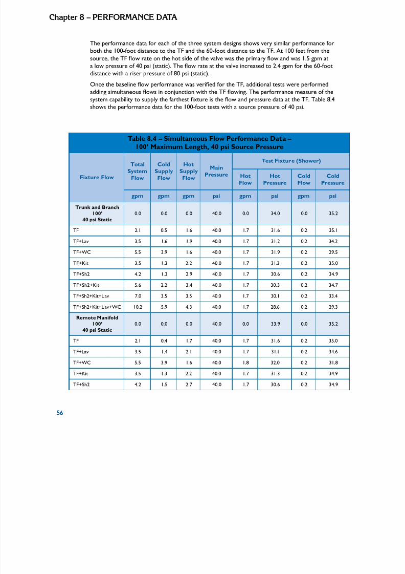
5/11/2018 Pex Design Guide - slidepdf.com
http://slidepdf.com/reader/full/pex-design-guide-55a0d1ab10986 66/128
56
Chapte 8 – PErForMAnCE dATA
The performance data for each of the three system designs shows very similar performance forboth the 100-foot distance to the TF and the 60-foot distance to the TF. At 100 feet from the
source, the TF ow rate on the hot side of the valve was the primary ow and was 1.5 gpm at
a low pressure of 40 psi (static). The ow rate at the valve increased to 2.4 gpm for the 60-foot
distance with a riser pressure of 80 psi (static).
Once the baseline ow performance was veried for the TF, additional tests were performedadding simultaneous ows in conjunction with the TF owing. The performance measure of the
system capability to supply the farthest xture is the ow and pressure data at the TF. Table 8.4
shows the performance data for the 100-foot tests with a source pressure of 40 psi.
Table 8.4 – Simultaneous Flow Performance Data – 100’ Maximum Length, 40 psi Source Pressure
Fixture Flow
Total
SystemFlow
Cold
SupplyFlow
Hot
SupplyFlow
Main
Pressure
Test Fixture (Shower)
Hot
Flow
Hot
Pressure
Cold
Flow
Cold
Pressure
gpm gpm gpm psi gpm psi gpm psi
Trunk and Branch100’ 0.0 0.0 0.0 40.0 0.0 34.0 0.0 35.2
40 psi Static
TF 2.1 0.5 1.6 40.0 1.7 31.6 0.2 35.1
TF+Lav 3.5 1.6 1.9 40.0 1.7 31.2 0.2 34.2
TF+WC 5.5 3.9 1.6 40.0 1.7 31.9 0.2 29.5
TF+Kit 3.5 1.3 2.2 40.0 1.7 31.3 0.2 35.0
TF+Sh2 4.2 1.3 2.9 40.0 1.7 30.6 0.2 34.9
TF+Sh2+Kit 5.6 2.2 3.4 40.0 1.7 30.3 0.2 34.7
TF+Sh2+Kit+Lav 7.0 3.5 3.5 40.0 1.7 30.1 0.2 33.4
TF+Sh2+Kit+Lav+WC 10.2 5.9 4.3 40.0 1.7 28.6 0.2 29.3
Remote Manifold
100’ 0.0 0.0 0.0 40.0 0.0 33.9 0.0 35.2
40 psi Static
TF 2.1 0.4 1.7 40.0 1.7 31.6 0.2 35.0
TF+Lav 3.5 1.4 2.1 40.0 1.7 31.1 0.2 34.6
TF+WC 5.5 3.9 1.6 40.0 1.8 32.0 0.2 31.8
TF+Kit 3.5 1.3 2.2 40.0 1.7 31.3 0.2 34.9
TF+Sh2 4.2 1.5 2.7 40.0 1.7 30.6 0.2 34.9
56

5/11/2018 Pex Design Guide - slidepdf.com
http://slidepdf.com/reader/full/pex-design-guide-55a0d1ab10986 67/128
5
Chapte 8 – PErForMAnCE dAT
Table 8.4 – Simultaneous Flow Performance Data – 100’ Maximum Length, 40 psi Source Pressure (continued)
Fixture Flow
TotalSystem
Flow
ColdSupply
Flow
HotSupply
Flow
Main
Pressure
Test Fixture (Shower)
HotFlow HotPressure ColdFlow ColdPressure
gpm gpm gpm psi gpm psi gpm psi
TF+Sh2+Kit 5.6 2.4 3.2 40.0 1.7 30.5 0.2 34.7
TF+Sh2+Kit+Lav 7.0 3.6 3.4 40.0 1.7 30.0 0.2 34.0
TF+Sh2+Kit+Lav+WC 10.2 6.2 4.0 40.0 1.7 29.8 0.2 30.8
Home-Run 100’40 psi Static
0.0 0.0 0.0 40.0 0.0 34.0 0.0 35.2
TF 2.1 0.4 1.7 40.0 1.7 29.3 0.2 35.0
TF+Lav 3.5 1.2 2.3 40.0 1.7 29.2 0.2 35.0
TF+WC 5.5 3.7 1.8 40.0 1.7 29.4 0.2 35.0
TF+Kit 3.5 1.2 2.3 40.0 1.7 29.0 0.2 35.0
TF+Sh2 4.2 1.5 2.8 40.0 1.7 28.6 0.2 35.0
TF+Sh2+Kit 5.6 2.3 3.3 40.0 1.7 28.6 0.2 34.9
TF+Sh2+Kit+Lav 7.0 3.3 3.7 40.0 1.7 28.4 0.2 34.8
TF+Sh2+Kit+Lav+WC 10.2 6.3 3.9 40.0 1.7 28.7 0.2 34.6
TF = Test Shower Fixture, 15’ elevation; Lav = Lavatory, both valves open, 15’ elevation
WC = Water Closet, tank type, 15’ elevation; Kit = Kitchen, mid-position, 4’ elevationSh2 = 2nd Shower, full open valve, 5’ elevation
Based on the simultaneous ow performance data, all systems continued to supply adequate
pressure and ow to the remote TF located 100 feet from the source. With the source
pressure of 40 psi, the maximum system ow rate was 8.0 gpm; 5.0 gpm to the cold supply
xtures and 3.0 gpm to the hot supply xtures. Table 8.5 shows similar results with a system
design of 60 feet to the TF.
5
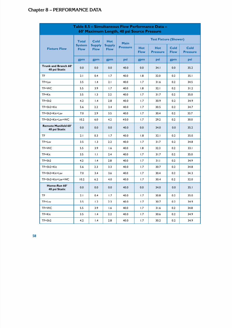
5/11/2018 Pex Design Guide - slidepdf.com
http://slidepdf.com/reader/full/pex-design-guide-55a0d1ab10986 68/128
58
Chapte 8 – PErForMAnCE dATA
Table 8.5 – Simultaneous Flow Performance Data – 60’ Maximum Length, 40 psi Source Pressure
Fixture Flow
TotalSystem
Flow
ColdSupply
Flow
HotSupply
Flow
Main
Pressure
Test Fixture (Shower)
HotFlow HotPressure ColdFlow ColdPressure
gpm gpm gpm psi gpm psi gpm psi
Trunk and Branch 60’40 psi Static
0.0 0.0 0.0 40.0 0.0 34.1 0.0 35.2
TF 2.1 0.4 1.7 40.0 1.8 32.0 0.2 35.1
TF+Lav 3.5 1.4 2.1 40.0 1.7 31.6 0.2 34.5
TF+WC 5.5 3.9 1.7 40.0 1.8 32.1 0.2 31.2
TF+Kit 3.5 1.3 2.2 40.0 1.7 31.7 0.2 35.0
TF+Sh2 4.2 1.4 2.8 40.0 1.7 30.9 0.2 34.9
TF+Sh2+Kit 5.6 2.2 3.4 40.0 1.7 30.5 0.2 34.7
TF+Sh2+Kit+Lav 7.0 2.9 3.5 40.0 1.7 30.4 0.2 33.7
TF+Sh2+Kit+Lav+WC 10.2 6.0 4.2 40.0 1.7 29.2 0.2 30.0
Remote Manifold 60’40 psi Static
0.0 0.0 0.0 40.0 0.0 34.0 0.0 35.2
TF 2.1 0.3 1.7 40.0 1.8 32.1 0.2 35.0
TF+Lav 3.5 1.3 2.2 40.0 1.7 31.7 0.2 34.8
TF+WC 5.5 3.9 1.6 40.0 1.8 32.3 0.2 33.1
TF+Kit 3.5 1.1 2.4 40.0 1.7 31.7 0.2 35.0
TF+Sh2 4.2 1.4 2.8 40.0 1.7 31.1 0.2 34.9
TF+Sh2+Kit 5.6 2.3 3.3 40.0 1.7 30.7 0.2 34.8
TF+Sh2+Kit+Lav 7.0 3.4 3.6 40.0 1.7 30.4 0.2 34.3
TF+Sh2+Kit+Lav+WC 10.2 6.2 4.0 40.0 1.7 30.4 0.2 32.0
Home-Run 60’40 psi Static
0.0 0.0 0.0 40.0 0.0 34.0 0.0 35.1
TF 2.1 0.4 1.7 40.0 1.7 30.8 0.2 35.0
TF+Lav 3.5 1.2 2.3 40.0 1.7 30.7 0.2 34.9
TF+WC 5.5 3.9 1.6 40.0 1.7 31.6 0.2 34.8
TF+Kit 3.5 1.4 2.2 40.0 1.7 30.6 0.2 34.9
TF+Sh2 4.2 1.4 2.8 40.0 1.7 30.2 0.2 34.9
58

5/11/2018 Pex Design Guide - slidepdf.com
http://slidepdf.com/reader/full/pex-design-guide-55a0d1ab10986 69/128
5
Chapte 8 – PErForMAnCE dAT
Table 8.5 – Simultaneous Flow Performance Data – 60’ Maximum Length, 40 psi Source Pressure (continued)
Fixture Flow
TotalSystem
Flow
ColdSupply
Flow
HotSupply
Flow
Main
Pressure
Test Fixture (Shower)
HotFlow HotPressure ColdFlow ColdPressure
gpm gpm gpm psi gpm psi gpm psi
TF+Sh2+Kit 5.6 2.3 3.3 40.0 1.7 30.0 0.2 34.8
TF+Sh2+Kit+Lav 7.0 3.3 3.7 40.0 1.7 29.8 0.2 34.8
TF+Sh2+Kit+Lav+WC 10.2 6.5 3.7 40.0 1.7 30.3 0.2 34.5
TF = Test Shower Fixture, 15’ elevation; Lav = Lavatory, both va lves open, 15’ elevation
WC = Water Closet, tank type, 15’ elevation; Kit = Kitchen, mid-position, 4’ elevation
Sh2 = 2nd Shower, full open valve, 5’ elevation
The system performance with simultaneous ows was very similar to the previous 100-
foot test but with slightly lower pressure drops. A static pressure of 40 psi is considered to
be a minimum supply pressure. A summary of the results for the simultaneous ow system
performance at 60 and 80 psi source static pressure is shown in Appendix A.
Comparing the ow pressure and ow rate is a good way to determine the performance of a
plumbing system. The limitation is that the pressure at the base of the riser is dependent onthe size of the service line, meter, and water utility supply pressure. In order to describe andcompare the performance of each type of system, the pressure drop from the base of theriser to the farthest outlet (including elevation losses) can be evaluated. Figures 8.4 and 8.5
show the comparison of pressure drop based on various outlets in the system owing with the
resultant pressure drop at the farthest xture. Both gures indicate that the home-run system,
while having a higher pressure drop to the TF, has a more consistent pressure drop duringsimultaneous ow. The other systems, based on the trunk line feeding branch lines, continued
to show increasing pressure drop as more xtures were added to the system. In fact, when the
full set of xtures was operating simultaneously, the trunk and branch system pressure drop
exceeded that of the home-run and the remote manifold congurations. (The remote manifold
system is highly dependent on the system design, i.e., the location of the manifolds and thenumber of xtures connected to the manifold).
5

5/11/2018 Pex Design Guide - slidepdf.com
http://slidepdf.com/reader/full/pex-design-guide-55a0d1ab10986 70/128
60
Chapte 8 – PErForMAnCE dATA
Figure 8.4 – Pressure Drop Compari son, 100’ Distance to TF
Figure 8.5 – Pressure Drop Comparison, 60’ Distance to TF
60

5/11/2018 Pex Design Guide - slidepdf.com
http://slidepdf.com/reader/full/pex-design-guide-55a0d1ab10986 71/128
6
Chapte 8 – PErForMAnCE dAT
Wait Time for Hot Water
A signicant benet of PEX piping systems is the opportunity to reduce water and energy
waste by reducing the amount of time to deliver hot water to the outlet from the water heater.Though hard to quantify denitely, there are indications that hundreds of gallons of water per
year are wasted while waiting for hot water to reach the outlet. Tests were also performed on each of the three PEX system designs to compare the time it takes for hot water to be delivered to the test xture (TF). Figure 8.6 shows the results of
delivering hot water to the shower xture after the pipes were ushed with cold (city) water.
The results were normalized to keep the ow rates and temperature from the hot water tank
constant for all systems.
Figure 8.6 – Comparison of Hot Water Delivery Time
Water and time savings of between 30 percent and 40 percent were identied based on this
analysis of the home-run system over either the trunk and branch or remote manifold systemdesigns.
6

5/11/2018 Pex Design Guide - slidepdf.com
http://slidepdf.com/reader/full/pex-design-guide-55a0d1ab10986 72/128
62
Chapte 8 – PErForMAnCE dATA
Test Summary
A summary of the performance characteristics of each system is shown in Table 8.6. The dataindicates:
• Trunk and branch and remote manifold systems will supply one xture at a higher pressure
• Home-run systems will supply a more stable pressure to each xture when operatingsimultaneous xtures
• Home-run systems will deliver hot water to the outlet quicker, especially when the pipes areat room temperature
• Trunk and branch and remote manifold systems will deliver hot water quicker during
sequential ows
• All three system designs will supply sufcient ow and pressure to the outlets even when
the base riser pressure is 40 psi and the length to the farthest outlet is 100 feet.
Table 8.6 – Performance Summary, 100’ Maximum Distance
Test Fixture Test Fixture With Test Fixture
System
Only Simultaneous Only
Flow RateHot
PressureHot
Flow RateHot
PressureHot
Time to> 100°F
Hot Water
Time to> 110°F
Hot Water
gpm psi gpm psi sec sec
40 psi Static
T&B - 100’ 1.7 31.6 1.7 28.6
RM - 100’ 1.7 31.6 1.7 29.8
HR - 100’ 1.7 29.3 1.7 28.7
60 psi Static from 53°F
T&B - 100’ 2.2 50.0 2.1 44.4 71.9 90.9
RM - 100’ 2.2 49.7 2.1 46.3 71.6 89.3
HR - 100’ 2.1 46.4 2.1 45.6 46.3 56.8
80 psi Static
T&B - 100’ 2.6 68.7 2.4 61.6
RM - 100’ 2.6 68.7 2.5 63.0
HR - 100’ 2.6 63.6 2.4 62.0
62

5/11/2018 Pex Design Guide - slidepdf.com
http://slidepdf.com/reader/full/pex-design-guide-55a0d1ab10986 73/128
6
InSTALLATIon
Css-Like Plyethylee (PEX)Ht- a Cl-Wate distibti Systems
This chapter is extracted in its entirety from the Plastic Pipe and Fittings Association (PPFA)document entitled “Cross-Linked Polyethylene (PEX) Hot- and Cold-Water Distribution
Systems,” released in 2006, and is included with permission from the PPFA. It is provided as
a general reference to supply basic information regarding the installation process for PEXpiping in residential water service applications. It should not be used in place of the specic
manufacturers’ instructions for the installation of any particular system. Local codes provisionsmay vary, and should be consulted before beginning any piping installation.
Important Notice
The information in this manual was gathered from publicly available sources, including reports
of tests conducted by various independent entities under the test conditions specied in the
standards listed.
The contents of this manual are informational only and are not intended as an endorsement or
warranty with respect to any product or system.
The Plastic Pipe and Fittings Association (PPFA) and its members have no responsibilityfor the design, administration, results, or evaluation of any test. PPFA and its members
make no warranties, express or implied, as to: the tness of any product or system for any
particular purpose; the suitability of any product or system for any specic application; or the
performance of any product or system in actual construction.
Copyright © 2006 Plastic Pipe and Fittings Association
63

5/11/2018 Pex Design Guide - slidepdf.com
http://slidepdf.com/reader/full/pex-design-guide-55a0d1ab10986 74/128
64
Chapte 9 – InSTALLATIon
l ll i i i l li le
pl i ildi isi ll i li i
i i iti ll i l i i i
i i i
No product or system shou d be used or insta ed w thout rst rev ew ng a l app cab
umb ng or bu ng code prov ons and the manufacturer’s insta at on or app cat on
nstruct ons. Local code author es and the product or system manufacturer shou d beconsu ted w th respect to unreso ved quest ons or uncerta nt es.
In the event there is any con ct or incons stency between the content of th s manual and
the applicable building or plumbing code and the manufacturer’s installation or applicationinstructions, the codes and the instructions shall be followed.
Revision Policy
The PPFA Flexible Polyolen Hot and Cold Water Systems Product Line Committee is
responsible for revision of the manual. All suggestions and recommendations for revisionsshall be addressed to the Committee, which shall respond to them as promptly as reasonablypossible. The Committee shall review the manual in its entirety at least once every three (3)years.
Published by the Plastic Pipe and Fittings Association,
800 Roosevelt Road, Building C, Suite 312, Glen Ellyn, IL, 60137www.ppfahome.org
Copyright © 2006 Plastic Pipe and Fittings Association
64
Copyright © 2006 Plastic Pipe and Fittings Associa
5/11/2018 Pex Design Guide - slidepdf.com
http://slidepdf.com/reader/full/pex-design-guide-55a0d1ab10986 75/128
6
Chapte 9 – InSTALLATIo
Manual Content & Use
This manual contains information on the installation of Cross-linked Polyethylene (PEX) tubingfor hot- and cold-water distribution systems in residential and light commercial installationsusing tubing up to 1 inch diameter.
Information in this manual shall not be separated as it is often interrelated.Consult local codes for additional installation requirements.For additional information contact:Local ofcials having jurisdiction (for codes)
Manufacturer (for specic product information)
PPFA (for general installation instructions)
Plastics Pipe Institute (PPI)
Other Uses of Cross-Linked Polyethylene (PEX) Tubing
Hydronic Radiant Heating
Heat Pump Applications
Other Uses with Similar Service Requirements
Consult tubing manufacturer for details.
6
Copyright © 2006 Plastic Pipe and Fittings Association
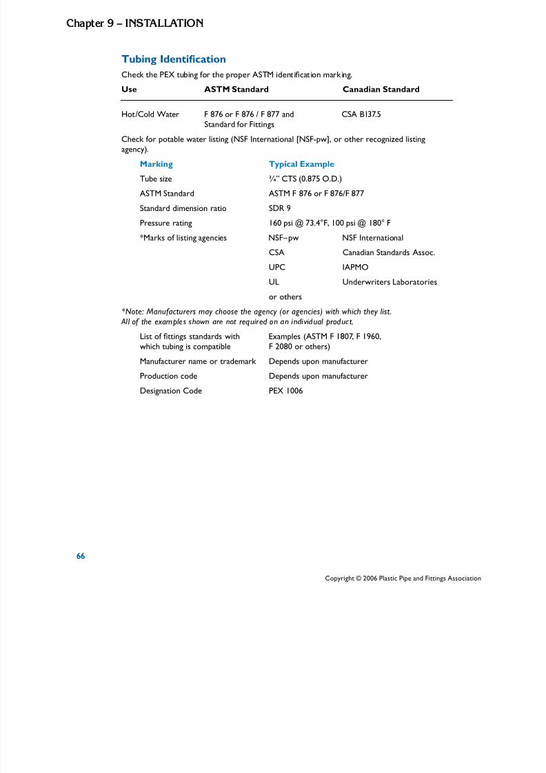
5/11/2018 Pex Design Guide - slidepdf.com
http://slidepdf.com/reader/full/pex-design-guide-55a0d1ab10986 76/128
66
Chapte 9 – InSTALLATIon
i i i i
Tubing Identication
Check the PEX tub ng for the proper ASTM ident cat on mark ng.
Use ASTM Standard Canadian Standard
Hot/Cold Water F 876 or F 876 / F 877 and CSA B137.5Standard for Fittings
Check for potable water listing (NSF International [NSF-pw], or other recognized listingagency).
Marking Typical Example
Tube sizeASTM StandardStandard dimension ratioPressure rating
¾” CTS (0.875 O.D.)
ASTM F 876 or F 876/F 877
SDR 9
160 psi @ 73.4°F, 100 psi @ 180° F
*Marks of listing agencies NSF–pw NSF International
CSA Canadian Standards Assoc.
UPC IAPMO
UL Underwriters Laboratories
or others
*Note: Manufacturers may choose the agency (or agencies) with which they list. All of the examples shown are not required on an individual product.
List of ttings standards with Examples (ASTM F 1807, F 1960,
which tubing is compatible
Manufacturer name or trademark Production codeDesignation Code
F 2080 or others)Depends upon manufacturer
Depends upon manufacturer
PEX 1006
66
Copyright © 2006 Plastic Pipe and Fittings Associa

5/11/2018 Pex Design Guide - slidepdf.com
http://slidepdf.com/reader/full/pex-design-guide-55a0d1ab10986 77/128
6
Chapte 9 – InSTALLATIo
Fitting Identication
All ttings shall be marked with manufacturer’s name or trademark or other identication
mark, plus the ASTM standard specication with which the tting complies.
Applicable Standards
• ASTM F 876 - Specication for Cross-linked Polyethylene (PEX) Tubing
• ASTM F 877 - Specication for Cross-linked Polyethylene (PEX) Plastic Hot and Cold
Water Distribution Systems
• ASTM F 1807 - Specication for Metal Insert Fittings Utilizing a Copper Crimp Ring for
SDR 9 Cross-linked Polyethylene (PEX) Tubing
• ASTM F 1960 - Specication for Cold Expansion Fittings with PEX Reinforcing Rings for
use with Cross-linked Polyethylene (PEX) Tubing
• ASTM F 2159 - Standard Specication for Plastic Insert Fittings Utilizing a Copper
Crimp Ring for SDR9 Cross-linked Polyethylene (PEX) Tubing
• ASTM F 2080 - Standard Specication for Cold-Expansion Fittings With Metal
Compression-Sleeves for Cross-Linked Polyethylene (PEX) Pipe
• ASTM F 2098 - Standard Specication for Stainless Steel Clamps for Securing SDR9
Cross-linked polyethylene (PEX) Tubing to Metal Insert Fittings
• CSA B137.5 - Cross-linked Polyethylene (PEX) Tubing Systems for Pressure Applications
Limitations on PEX Use
Do not use in applications where the temperature of the water could exceed 180oF at 100
psi unless specically approved in the code, e.g., water heater relief line. See manufacturer’srecommendations for higher operating temperatures at lower pressures.
Do not use in any application where tubing will be exposed to direct sunlight.
Do not allow tubing to come in extended contact with any of at least the commonlyencountered construction materials listed below: (This list is not all-inclusive.)
• Pipe thread sealing compounds
• Fire wall penetration sealing compounds. Exception: water soluble, gypsum-based caulking or other sealants approved by the PEX tube manufacturer
• Petroleum-based materials or sealants such as:• Kerosene, Benzene, Gasoline, Solvents, Fuel Oils, Cutting Oils, Asphaltic Paint,
and Asphaltic Road Materials, Acetone, Toluene, and/or Xylene
Consult your tubing manufacturer if you have questions about these or any other materials notlisted.
Do not place any PEX tubing in heavily contaminated soils or other heavily contaminated
environments.
6
Copyright © 2006 Plastic Pipe and Fittings Association

5/11/2018 Pex Design Guide - slidepdf.com
http://slidepdf.com/reader/full/pex-design-guide-55a0d1ab10986 78/128
68
Chapte 9 – InSTALLATIon
i i i ii i i
i i ipi
i ipi imi i
Do not use tub ng w th gouges, cuts, cracks, abras ons, evidence of chem cal attack, or otherdefects, or tub ng wh ch has been crushed or k nked.
Do not use PEX in sw mm ng pool p ng systems.
Copper or brass tt ngs, when used in a PEX p ng system, have the same l tat ons as
copper or brass ttings used in plumbing or heating systems.Store ttings in containers that are free of oil, grease, lubricants, solder ux, or other chemicals and away from corrosive atmospheres (Example: Ammonia).
TUBING INSTALLATION PRACTICES
General Installation
Review all limitations on the use of cross-linked polyethylene tubing, and the tting system you
have selected to use.Keep tubing a minimum of 12 inches vertically or 6 inches horizontally from sources of high heat, such as recessed light xtures, ue gas vents, or heating appliances.
Do not install PEX tubing downstream of any point-of-use water heater or immersed
coil heater in a boiler where the outputtemperature can exceed 180oF or closer than6 inches upstream. Contact manufacturer forrecommended metallic transition ttings.
PEX tubing may be connected directly toresidential electric water heaters, if the localcode and manufacturer’s instructions allow.
When connecting PEX tube to gas water heaters, the tube must be kept at least 6 inches away
from the exhaust vent of the heater. Flexible metal water heater connectors may be needed insome instances.
Hose bibbs shall not be supported by PEX tubing. Hose bibbs shall be anchored to prevent strain on PEX tubing.Use only continuous length tubing (no ttings) when installing PEX
under or within a slab. Protect PEX tubing with nonmetallic sleeves where it penetrates a slab or foundation. (Examples: PVC bend guides, PE sleeving). Protect tubing from nail damage where
appropriate.
Nail plate
68
Copyright © 2006 Plastic Pipe and Fittings Associa
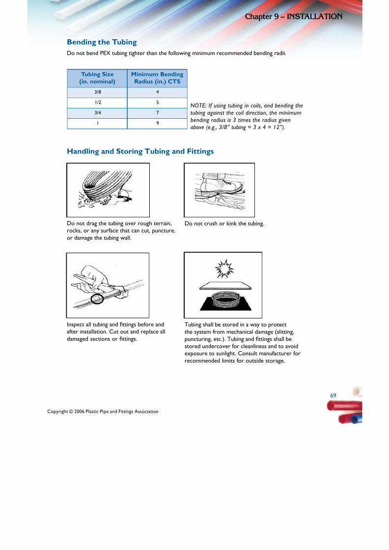
5/11/2018 Pex Design Guide - slidepdf.com
http://slidepdf.com/reader/full/pex-design-guide-55a0d1ab10986 79/128
6
Chapte 9 – InSTALLATIo
Bending the Tubing
Do not bend PEX tubing tighter than the following minimum recommended bending radii.
Tubing Size Minimum Bending
(in. nominal) Radius (in.) CTS3/8 4
1/2 5
3/4 7
1 9
NOTE: If using tubing in coils, and bending the
tubing against the coil direction, the minimumbending radius is 3 times the radius givenabove (e.g., 3/8” tubing = 3 x 4 = 12”).
Handling and Storing Tubing and Fittings
Do not drag the tubing over rough terrain, Do not crush or kink the tubing.rocks, or any surface that can cut, puncture, or damage the tubing wall.
Inspect all tubing and ttings before and
after installation. Cut out and replace alldamaged sections or ttings.
Tubing shall be stored in a way to protect
the system from mechanical damage (slitting,puncturing, etc.). Tubing and ttings shall be
stored undercover for cleanliness and to avoidexposure to sunlight. Consult manufacturer for
recommended limits for outside storage.
Copyright © 2006 Plastic Pipe and Fittings Association
6

5/11/2018 Pex Design Guide - slidepdf.com
http://slidepdf.com/reader/full/pex-design-guide-55a0d1ab10986 80/128
70
Chapte 9 – InSTALLATIon
Pl i i i
Tubing Supports:
Selection and Inspection
ast c hangers and straps are recommended, but metal supports wh ch are des gned for usewith plastic tubing can be used.
Do not use supports that pinch or cut the tubing.Support should allow free tubing movement.
Inspect all supports prior to installation to ensure thatsharp edges do not exist that can damage the tubing.
Support Spacing and Location
Horizontal Tubing Support Spacing
Nominal Tubing Diameter (in.) Spacing (in.)
3/8, 1/2, 3/4, 1 32
Vertical tubing shall be supported at every oor (8-feet to 10-feet height) and at the mid-oor
guide between oors.
When penetrating metal studs, utilize a properly-designed bushing or sleeving material on all
penetrations to protect tubing.
Tubing and ttings shall be installed without placing stress on the connection. Stress on
connections frequently occurs when tubing is not properly strapped at changes of directions.
ll iSee i ustrat ons for proper methods.
Correct Incorrect Correct
Copyright © 2006 Plastic Pipe and Fittings Associa

5/11/2018 Pex Design Guide - slidepdf.com
http://slidepdf.com/reader/full/pex-design-guide-55a0d1ab10986 81/128
7
Chapte 9 – InSTALLATIo
Expansion/Contraction of Tubing
Do not pull tubing tight during installation. This can cause excessive tensile forces on ttings
and connections when tubing cools and contracts. Allow 1/8-inch slack per foot of installedtubing. Expansion can usually be accommodated by the tubing’s exibility for sizes up to and
including 1 inch.
Hydraulic Shock (Pressure Surge)The following table provides the maximum pressure that will occur from rapid closure of avalve in the various tubing systems at a given velocity. The faster the velocity, the greater thepotential hydraulic shock (pressure surge).
Excessive hydraulic shock (pressure surge) may result in audible water hammer with metallicpiping systems, though this is highly unlikely with PEX tubing due to the exibility of the tubing
itself.
The table shows the additional hydraulic shock (pressure surge) that can occur in various typesof pipes at the water velocities shown when a fast-acting valve closes. Hydraulic shock pressureis in addition to the system static pressure (measured on site). To determine the instantaneous
total system pressure that occurs, add the hydraulic shock pressure to the static pressure.For normal plumbing installations, water hammer arrestors are not necessary with a PEXtubing system.
In predominantly metal piping systems in which PEX is used, it may be necessary to installwater hammer arrestors.
Hydraulic Shock (psi at 73 F)
Velocity (fps) 4 6 8 10
PEX 58 87 116 145
Coppper 200 300 400 505
Galvanized Steel 240 360 475 595
7
Copyright © 2006 Plastic Pipe and Fittings Association

5/11/2018 Pex Design Guide - slidepdf.com
http://slidepdf.com/reader/full/pex-design-guide-55a0d1ab10986 82/128
72
Chapte 9 – InSTALLATIon
ll i ld pl i l i ly si l li i i i l i l i
i i i i i l
i i i i ili
Manifold Plumbing Systems
The para el man fo umb ng concept is re at ve mp e. Each faucet or water out et is fedby its own ded cated l ne wh ch runs from a central man fo d. By provid ng each out et w th itsown d str but on l ne, the system offers qu eter water ow, more ba anced water pressure, a
dramat c reduct on in the number of tt red, and the abngs requ ty to save both water and
energy, versus traditional system designs.The following information applies to a PEX tubing plumbing manifold system in addition to the general limitations and installation information on PEX tubing and ttings in this manual.
• Manifolds can be installed in a horizontal or vertical position.
• In larger installations, with multiple water heaters, remote manifolds may be used to
handle groups of remote outlets.
• Each faucet or water outlet is fed by its own dedicated line from the manifold, which
may be located near the water supply or water heater.
• Tubing shall be run continuously and as directly as possible between manifold and
xture locations. Approved ttings may be used to repair kinked or damaged PEXdistribution lines, or to add to a distribution line that was mistakenly cut too shortduring installation. Excessive use of ttings is unnecessary.
• Shut-off valves can be placed at the manifold or xture. Check with your local
inspector.
• Tubing shall not be pulled tight. Leave slack to allow for expansion and contraction.
• Install tubing cautiously to avoid binding, kinking, or abrasion.
• Leave excess tubing at the beginning and end of runs for connection to xtures and the
manifolds.
• When running lines to a group of xtures, they may be bundled together, but must be
bundled loosely enough to allow individual tubing movement. Plastic ties may be used.
• Do not use tape when bundling tubing as it may restrict movement of tubing runs.
• When bundled lines pass through conventional structural members, cut a hole at thecenterline of the member. Consult the applicable code for maximum allowable hole
size.
• Identify and mark all lines at the manifold.
72
Copyright © 2006 Plastic Pipe and Fittings Associa
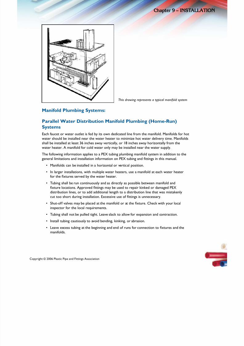
5/11/2018 Pex Design Guide - slidepdf.com
http://slidepdf.com/reader/full/pex-design-guide-55a0d1ab10986 83/128
7
Chapte 9 – InSTALLATIo
This drawing represents a typical manifold system
Manifold Plumbing Systems:
Parallel Water Distribution Manifold Plumbing (Home-Run)
Systems
Each faucet or water outlet is fed by its own dedicated line from the manifold. Manifolds for hotwater should be installed near the water heater to minimize hot water delivery time. Manifoldsshall be installed at least 36 inches away vertically, or 18 inches away horizontally from thewater heater. A manifold for cold water only may be installed near the water supply.
The following information applies to a PEX tubing plumbing manifold system in addition to thegeneral limitations and installation information on PEX tubing and ttings in this manual.
• Manifolds can be installed in a horizontal or vertical position.
• In larger installations, with multiple water heaters, use a manifold at each water heaterfor the xtures served by the water heater.
• Tubing shall be run continuously and as directly as possible between manifold andxture locations. Approved ttings may be used to repair kinked or damaged PEX
distribution lines, or to add additional length to a distribution line that was mistakenly
cut too short during installation. Excessive use of ttings is unnecessary.
• Shut-off valves may be placed at the manifold or at the xture. Check with your local
inspector for the local requirements.• Tubing shall not be pulled tight. Leave slack to allow for expansion and contraction.
• Install tubing cautiously to avoid bending, kinking, or abrasion.
• Leave excess tubing at the beginning and end of runs for connection to xtures and the
manifolds.
7
Copyright © 2006 Plastic Pipe and Fittings Association
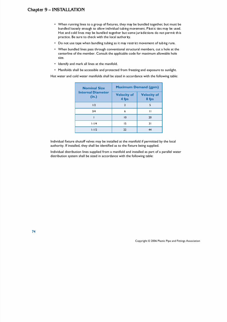
5/11/2018 Pex Design Guide - slidepdf.com
http://slidepdf.com/reader/full/pex-design-guide-55a0d1ab10986 84/128
74
Chapte 9 – InSTALLATIon
• i i l
l l ll i i l ic ti
ld li l i i i i isi i i
• li i i i
When runn ng l nes to a group of xtures, they may be bund ed together, but must be
bund ed loose y enough to a ow ind vidual tub ng movement. P ast es may be used.
Hot and co nes may be bund ed together but some jur sd ct ons do not perm t thpract ce. Be sure to check w th the local author ty.
Do not use tape when bund ng tub ng as it may restr ct movement of tub ng runs.
• When bundled lines pass through conventional structural members, cut a hole at thecenterline of the member. Consult the applicable code for maximum allowable holesize.
• Identify and mark all lines at the manifold.
• Manifolds shall be accessible and protected from freezing and exposure to sunlight.
Hot water and cold water manifolds shall be sized in accordance with the following table:
Nominal SizeInternal Diameter
(in.)
Maximum Demand (gpm)
Velocity of 4 fps
Velocity of 8 fps
1/2 2 5
3/4 6 11
1 10 20
1-1/4 15 31
1-1/2 22 44
Individual xture shutoff valves may be installed at the manifold if permitted by the local
authority. If installed, they shall be identied as to the xture being supplied.
Individual distribution lines supplied from a manifold and installed as part of a parallel waterdistribution system shall be sized in accordance with the following table:
74
Copyright © 2006 Plastic Pipe and Fittings Associa

5/11/2018 Pex Design Guide - slidepdf.com
http://slidepdf.com/reader/full/pex-design-guide-55a0d1ab10986 85/128
7
Chapte 9 – InSTALLATIo
Minimum Sizes of Fixture Water Supply Linesin Manifold Systems
FixtureMinimum Pipe Size
(in.)
Bathtubs and Whirlpool Tubs 1/2
Tub and Shower 1/2
Shower only (Single Head) 3/8
Bathroom Lavatory 3/8
Water Closet, Residential 3/8
Water Closet, Commercial 1/2
Kitchen Sink 3/8
Laundry Washing Machine 3/8
Utility Sink 3/8
Bar Sink 3/8
Urinal , Flush Tank 3/8
Urinal , Flush Valve 1/2
Thawing PEX Tubing Systems
PEX tubing systems should not be intentionally subjected to freezing.
Do not use open torch or excessive heat to thaw PEX tubing.Tubing failure or damage can result. Use a hot air gun or a blowdryer.
Heat (DO NOT USE A TORCH) must be applied directly to the
frozen tubing section. Temperature on tubing shall not exceed180oF.
Several suitable methods exist to thaw PEX tubing. They include:
• A commercial system which pumps heated water through the tube to the ice blockage, and returns the cooled water for reheating
• Wet hot towels
• Hot water
• Hand-held hair dryer
• Low wattage electrical heating tape
7
Copyright © 2006 Plastic Pipe and Fittings Association
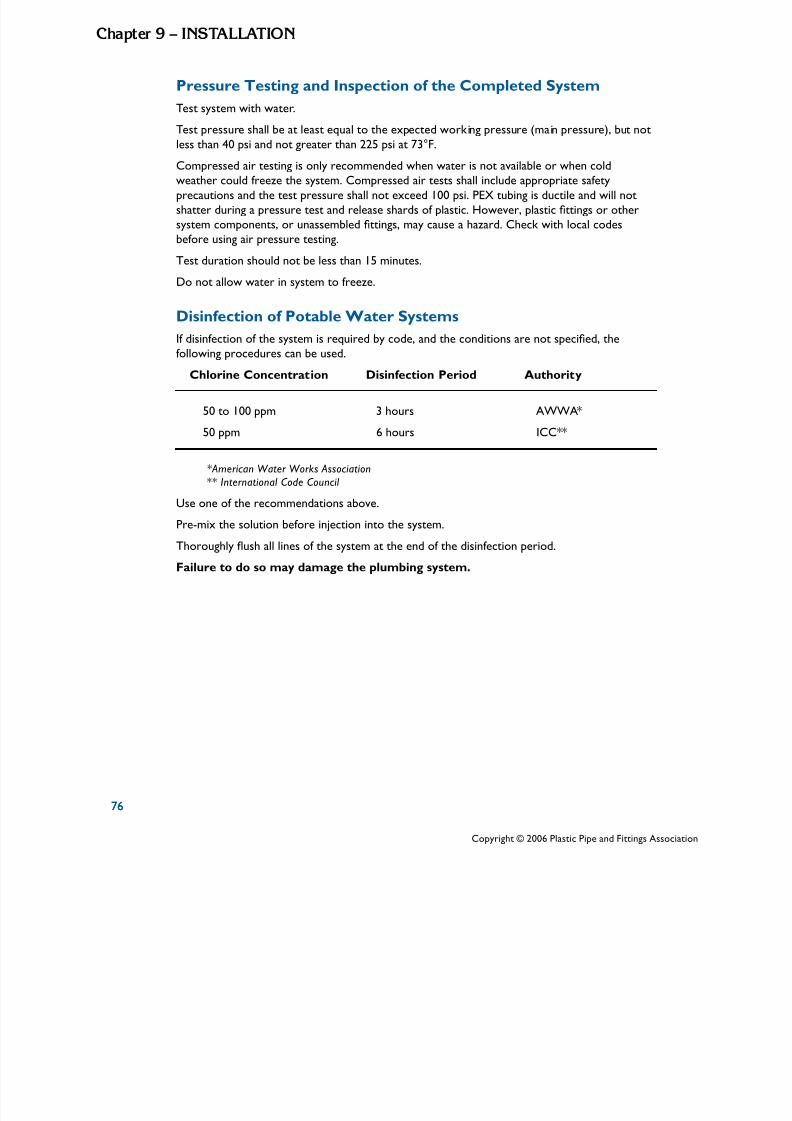
5/11/2018 Pex Design Guide - slidepdf.com
http://slidepdf.com/reader/full/pex-design-guide-55a0d1ab10986 86/128
76
Chapte 9 – InSTALLATIon
i
l i il
Pressure Testing and Inspection of the Completed System
Test system w th water.
Test pressure sha l be at least equal to the expected work ng pressure (ma n pressure), but notess than 40 psi and not greater than 225 psi at 73°F.
Compressed air testing is only recommended when water is not available or when coldweather could freeze the system. Compressed air tests shall include appropriate safety
precautions and the test pressure shall not exceed 100 psi. PEX tubing is ductile and will notshatter during a pressure test and release shards of plastic. However, plastic ttings or other
system components, or unassembled ttings, may cause a hazard. Check with local codes
before using air pressure testing.Test duration should not be less than 15 minutes.Do not allow water in system to freeze.Disinfection of Potable Water Systems
If disinfection of the system is required by code, and the conditions are not specied, thefollowing procedures can be used.
Chlorine Concentration Disinfection Period Authority
50 to 100 ppm 3 hours AWWA*
50 ppm 6 hours ICC**
*American Water Works Assoc iation** International Code Council
Use one of the recommendations above.
Pre-mix the solution before injection into the system.Thoroughly ush all lines of the system at the end of the disinfection period.
Failure to do so may damage the plumbing system.
76
Copyright © 2006 Plastic Pipe and Fittings Associa
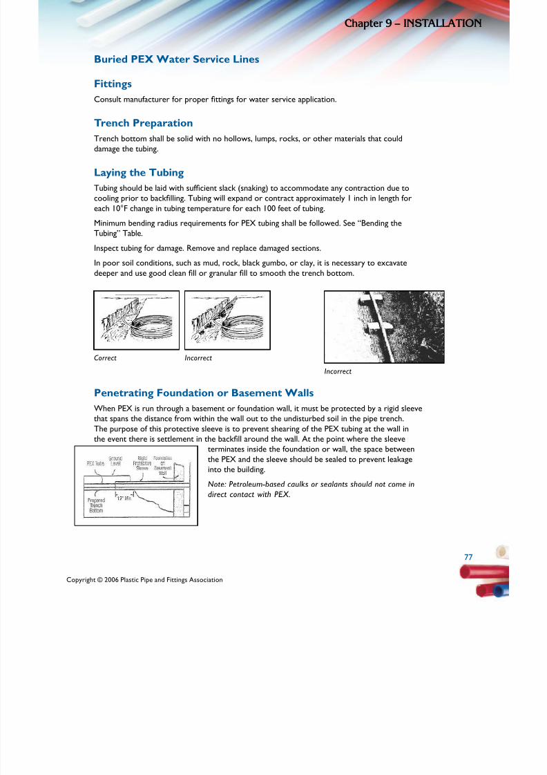
5/11/2018 Pex Design Guide - slidepdf.com
http://slidepdf.com/reader/full/pex-design-guide-55a0d1ab10986 87/128
7
Chapte 9 – InSTALLATIo
Buried PEX Water Service Lines
Fittings
Consult manufacturer for proper ttings for water service application.
Trench Preparation
Trench bottom shall be solid with no hollows, lumps, rocks, or other materials that coulddamage the tubing.
Laying the Tubing
Tubing should be laid with sufcient slack (snaking) to accommodate any contraction due to
cooling prior to backlling. Tubing will expand or contract approximately 1 inch in length for
each 10°F change in tubing temperature for each 100 feet of tubing. Minimum bending radius requirements for PEX tubing shall be followed. See “Bending the Tubing” Table.Inspect tubing for damage. Remove and replace damaged sections. In poor soil conditions, such as mud, rock, black gumbo, or clay, it is necessary to excavate deeper and use good clean ll or granular ll to smooth the trench bottom.
Correct Incorrect
Incorrect
Penetrating Foundation or Basement Walls
When PEX is run through a basement or foundation wall, it must be protected by a rigid sleevethat spans the distance from within the wall out to the undisturbed soil in the pipe trench.
The purpose of this protective sleeve is to prevent shearing of the PEX tubing at the wall inthe event there is settlement in the backll around the wall. At the point where the sleeve
terminates inside the foundation or wall, the space betweenthe PEX and the sleeve should be sealed to prevent leakage
into the building.
Note: Petroleum-based caulks or sealants should not come in
direct contact with PEX.
Copyright © 2006 Plastic Pipe and Fittings Association
7

5/11/2018 Pex Design Guide - slidepdf.com
http://slidepdf.com/reader/full/pex-design-guide-55a0d1ab10986 88/128
78
Chapte 9 – InSTALLATIon
l i l l i i i ll i lli
Slab-on-Grade Installation
Laying and Supporting Tubing under Slab
On y cont nuous y-run engths of tub ng w thout tt ngs sha be used when nsta ng PEX under
a slab. All connections shall be outside or above the slab. Tubing shall be completely buried by
a suitable, easily compacted, backll material such as sand or pea gravel. PEX tubing should beinstalled under the rebar, re-mesh, or tensioning cables in the slab. PEX tubing shall be coveredor fastened to prevent the tubing from oating or being pulled up to the slab surface.
PEX tubing does not have to be sleeved its entire length where it lies beneath a slab. PEXtubing shall be protected with a non-metallic sleeve where it comes through the slab. BecausePEX is exible, it may need support to keep it from falling back onto the slab once it exits the
slab. To prevent this, PEX can be carefully tied to re-bar, wood stakes or rigid drain pipe for
support. This will serve to protect the PEX tubing as the slab is poured, leveled and smoothedand from subsequent framing and construction work.
Protection of Tubing and Fittings from UV Exposureafter the Pour
Due to the nature of slab-on-grade installations, tubing and ttings may be exposed to UV
light for unspecied periods of time after the slab is poured and before the structure is framed
and enclosed. To prevent damage from UV exposure, PEX tubing and ttings that are exposed
above the slab shall be wrapped with an opaque covering such as black polyethylene bags or
sheeting immediately after the pouring of the slab. This covering should extend down to thesurface of the slab to protect all of the tube above the slab from excessive UV exposure. Forspecic limitations on UV exposure, consult the PEX tube manufacturer.
Backlling
Do not use clay, silt, or rocky backll. Remove the construction materials, trash, or foreign
objects from trench prior to backlling.
The tubing and ttings should be surrounded with good clean ll, or sand, or river run gravel of
1/2-inch maximum particle size.
Compact the initial backll around the tubing to provide adequate tubing support and
prevent settlement. It is particularly important to adequately compact the soil around the tapconnection.
It is recommended that the tubing be pressurized with water prior to backlling to reveal any
damage.
78
Copyright © 2006 Plastic Pipe and Fittings Associa
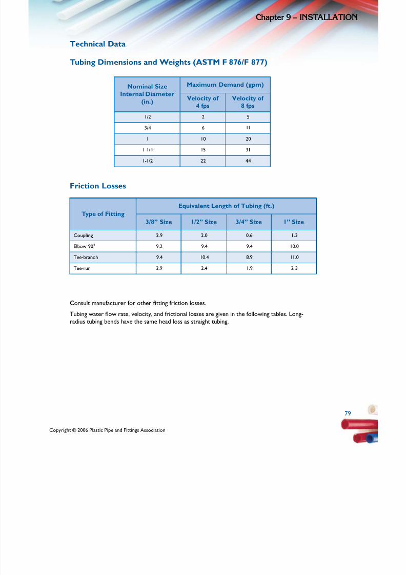
5/11/2018 Pex Design Guide - slidepdf.com
http://slidepdf.com/reader/full/pex-design-guide-55a0d1ab10986 89/128
7
/
1/2 2 5
3/4 6
1
/4
/2
Chapte 9 – InSTALLATIo
Technical Data
Tubing Dimensions and Weights (ASTM F 876 F 877)
Nominal SizeInternal Diameter
(in.)
Maximum Demand (gpm)
Velocity of 4 fps
Velocity of 8 fps
11
10 20
1-1 15 31
1-1 22 44
Friction Losses
Type of Fitting
Equivalent Length of Tubing (ft.)
3/8” Size 1/2” Size 3/4” Size 1” Size
Coupling 2.9 2.0 0.6 1.3
Elbow 90° 9.2 9.4 9.4 10.0
Tee-branch 9.4 10.4 8.9 11.0
Tee-run 2.9 2.4 1.9 2.3
Consult manufacturer for other tting friction losses.Tubing water ow rate, velocity, and frictional losses are given in the following tables. Long- radius tubing bends have the same head loss as straight tubing.
Copyright © 2006 Plastic Pipe and Fittings Association
7

5/11/2018 Pex Design Guide - slidepdf.com
http://slidepdf.com/reader/full/pex-design-guide-55a0d1ab10986 90/128
80
Chapte 9 – InSTALLATIon
/
3/ 1/ 3/
1
2
3
4
5
6
7
8
9
Friction Loss and Velocity vs. Flow Rate
PEX Plumbing Tubing (CTS) (ASTM F 876 F 877)
Nominal Size
Average ID
8”
0.350
2”
0.475
4”
0.671
1”
0.863
GPMFriction
LossVelocity
FrictionLoss
VelocityFriction
LossVelocity
FrictionLoss
Veloc
7.0 3.33 1.6 1.81 0.3 0.96 0.1 0.55
25.4 6.67 5.8 3.62 1.1 1.81 0.3 1.10
53.9 10.00 12.2 5.43 2.3 2.72 0.7 1.65
91.8 13.34 20.8 7.24 3.9 3.63 1.1 2.19
31.4 9.05 5.9 4.54 1.7 2.74
44.0 10.86 8.2 5.44 2.4 3.29
58.6 12.67 10.9 6.35 3.2 3.84
14.0 7.26 4.1 4.39
17.4 8.17 5.1 4.94
10 21.1 9.07 6.2 5.48
11 25.2 9.98 7.4 6.03
12 29.6 10.89 8.7 6.58
13 34.3 11.79 10.1 7.13
14 39.4 12.70 11.6 7.68
15 13.2 8.23
16 14.8 8.78
NOTE: Friction Loss based on Hazen-Williams Formula (C = 150)CTS Tubing manufactured per ASTM F 876/F 877
Friction Loss (F. Loss) is expressed as -psi per 100 ft. of tubing Velocity (VEL) feet per second
Copyright © 2006 Plastic Pipe and Fittings Associa

5/11/2018 Pex Design Guide - slidepdf.com
http://slidepdf.com/reader/full/pex-design-guide-55a0d1ab10986 91/128
8
Chapte 9 – InSTALLATIo
Connection (Transition) to Other Piping Materials
Solder copper transition ttings onto the copper pipe and allow cooling before connecting to
PEX tubing. High heat (greater than 180°F) may damage the PEX tubing. Do not use plastic male threads or non-gasketed female threads when making a connection to metal threads. Use only manufacturer’s recommended transition ttings.When making connections to CPVC pipe or ttings, use only approved transition ttings.
Joining Procedures Utilizing Metallic or Polymer Insert Fittings
Insert Fitting with a Black Copper Crimp Ring (ASTM F 1807 OR
ASTM F 2159)
Making a Connection
1. Cut tubing squarely, remove burrs, and slip the copper crimp ring onto the tube.
2. Insert tting into tube to the tube stop; do not apply lubricant or pipe dope on the insert tting. Position crimp ring 1/8 to 1/4 inch from end of tubing. To prevent ring from moving, squeeze the ring slightly with your ngers or a pair of pliers.
3. Center crimping tool jaws over the ring. Keeping both ring and tool square with tube, close the tool completely. DO NOT CRIMP TWICE.
4. It is recommended that the nished crimps be checked with the appropriate GO
NO/GO gauge. Slip gauge squarely over the crimped ring. If the “GO” slot of the gaugedoesn’t t across the crimped ring, the diameter of the ring is too large and the tting
must be cut out. DO NOT RECRIMP.
5. If the “NO/GO” slot of the gauge ts across the crimped ring, the diameter of the ring is too small and the tting must be replaced. Cut out the ring and tting, and replace them.
Incorrect Connections
The consequence of not following correct procedures is a potential for leaks.
• Ring crimped over end of tubeResult: Doesn’t cover enough ribs and/or tool could crush or crack tting
• Tool not at 90 degrees to tube when crimpedResult: Insufcient rib coverage; tubing dented
• Ring not completely covered by crimp tool Result: Ring distortion, non-uniform crimp
• Tubing not cut squarely
Result: Insufcient rib coverage
• Ring too far from pipe endResult: Insufcient rib coverage
8
Copyright © 2006 Plastic Pipe and Fittings Association
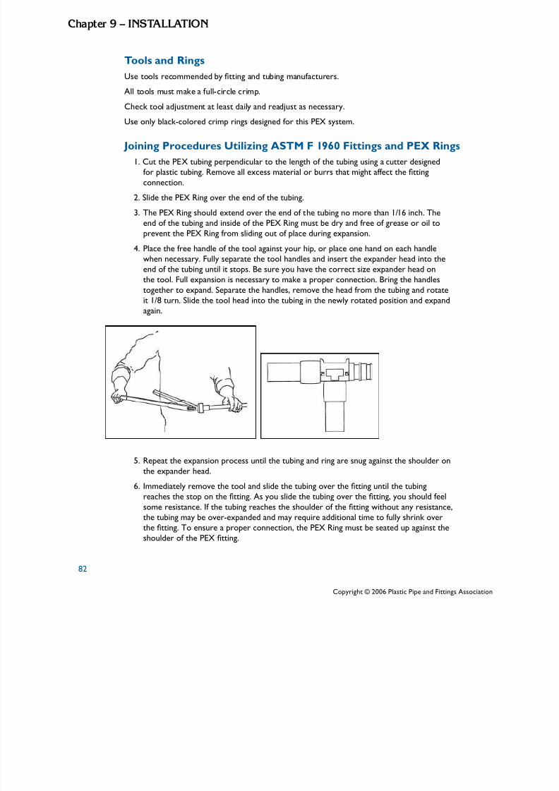
5/11/2018 Pex Design Guide - slidepdf.com
http://slidepdf.com/reader/full/pex-design-guide-55a0d1ab10986 92/128
82
Chapte 9 – InSTALLATIon
l i i
Al l ll i l i
il
Tools and Rings
Use too s recommended by tt ng and tub ng manufacturers.
l too s must make a fu -c rc e cr mp.
Check tool adjustment at least da y and readjust as necessary.
Use only black-colored crimp rings designed for this PEX system.
Joining Procedures Utilizing ASTM F 1960 Fittings and PEX Rings
1. Cut the PEX tubing perpendicular to the length of the tubing using a cutter designedfor plastic tubing. Remove all excess material or burrs that might affect the tting
connection.
2. Slide the PEX Ring over the end of the tubing.
3. The PEX Ring should extend over the end of the tubing no more than 1/16 inch. The
end of the tubing and inside of the PEX Ring must be dry and free of grease or oil toprevent the PEX Ring from sliding out of place during expansion.
4. Place the free handle of the tool against your hip, or place one hand on each handlewhen necessary. Fully separate the tool handles and insert the expander head into theend of the tubing until it stops. Be sure you have the correct size expander head onthe tool. Full expansion is necessary to make a proper connection. Bring the handles
together to expand. Separate the handles, remove the head from the tubing and rotateit 1/8 turn. Slide the tool head into the tubing in the newly rotated position and expandagain.
5. Repeat the expansion process until the tubing and ring are snug against the shoulder on
the expander head.
6. Immediately remove the tool and slide the tubing over the tting until the tubing
reaches the stop on the tting. As you slide the tubing over the tting, you should feel
some resistance. If the tubing reaches the shoulder of the tting without any resistance,
the tubing may be over-expanded and may require additional time to fully shrink overthe tting. To ensure a proper connection, the PEX Ring must be seated up against the
shoulder of the PEX tting.
Copyright © 2006 Plastic Pipe and Fittings Associa
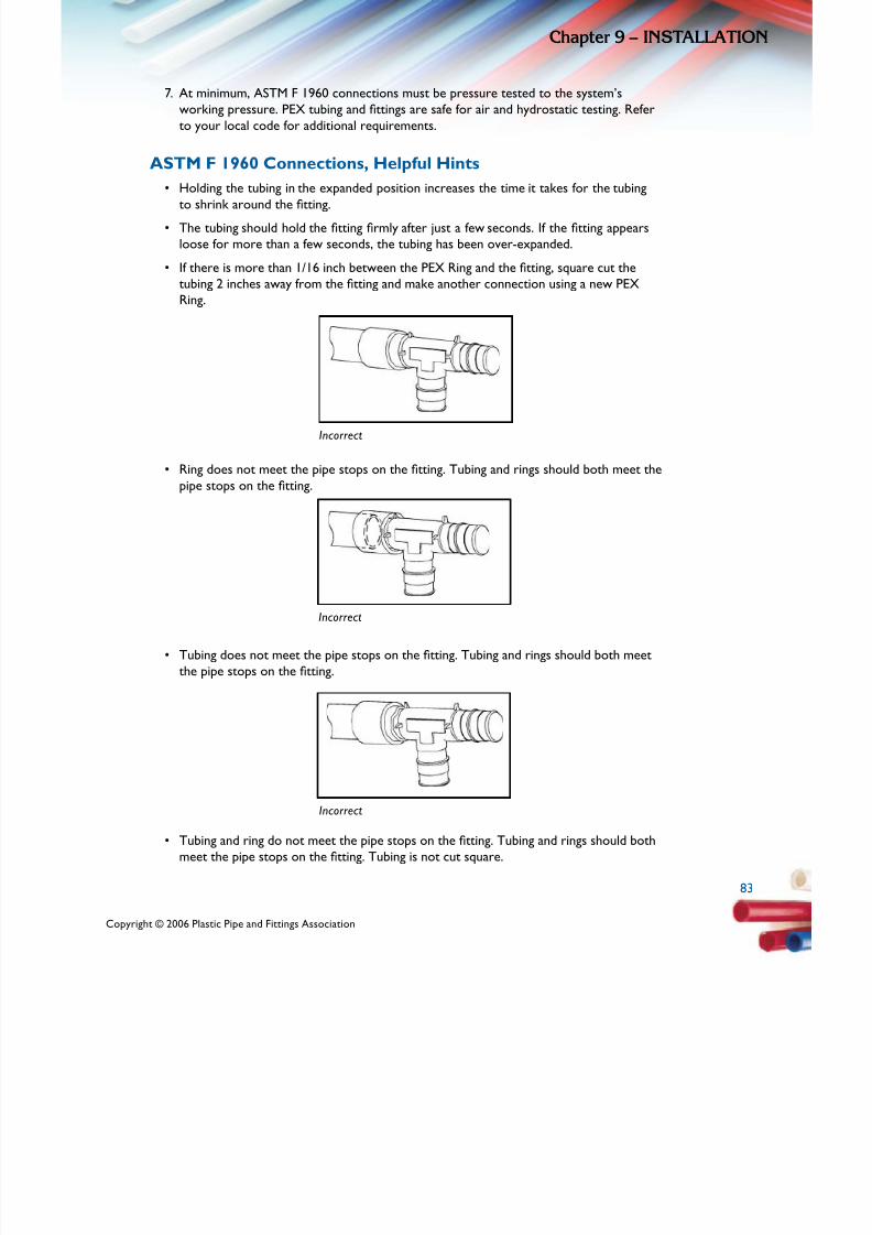
5/11/2018 Pex Design Guide - slidepdf.com
http://slidepdf.com/reader/full/pex-design-guide-55a0d1ab10986 93/128
8
Chapte 9 – InSTALLATIo
7. At minimum, ASTM F 1960 connections must be pressure tested to the system’sworking pressure. PEX tubing and ttings are safe for air and hydrostatic testing. Refer
to your local code for additional requirements.
ASTM F 1960 Connections, Helpful Hints
• Holding the tubing in the expanded position increases the time it takes for the tubingto shrink around the tting.
• The tubing should hold the tting rmly after just a few seconds. If the tting appears
loose for more than a few seconds, the tubing has been over-expanded.
• If there is more than 1/16 inch between the PEX Ring and the tting, square cut the
tubing 2 inches away from the tting and make another connection using a new PEX
Ring.
Incorrect
• Ring does not meet the pipe stops on the tting. Tubing and rings should both meet the
pipe stops on the tting.
Incorrect
• Tubing does not meet the pipe stops on the tting. Tubing and rings should both meet
the pipe stops on the tting.
Incorrect
• Tubing and ring do not meet the pipe stops on the tting. Tubing and rings should both
meet the pipe stops on the tting. Tubing is not cut square.
Copyright © 2006 Plastic Pipe and Fittings Association
8

5/11/2018 Pex Design Guide - slidepdf.com
http://slidepdf.com/reader/full/pex-design-guide-55a0d1ab10986 94/128
84
Chapte 9 – InSTALLATIon
i l i ili l i
Tools
There are a var ety of PEX expander too s that are des gned for ease of use when mak ngre ab e, permanent connect ons.
Joining Procedures Utilizing ASTM F 2080 Fittings and
Compression Sleeves
SummaryFittings shall be joined to PEX pipe by rst expanding the end of the pipe with the expander
tool, inserting the cold-expansion tting into expanded pipe, then pulling the compression-
sleeve over the PEX pipe and the tting, compressing the pipe between the compression sleeve
and the tting.
Procedure
1. Slide the compression sleeve onto the pipe so that the inside-beveled end is facing
toward the end of the pipe. Slide the compression-sleeve far enough down the pipe sothat it will not prevent expansion of the pipe.
2. Insert the head of the expander tool into the pipe. The expander tool segments shall
be centered inside the pipe.
3. Fully expand the pipe, holding it open for approximately 3 seconds, and remove the tool. Rotate the tool approximately 30°, insert the expander-tool into the pipe and repeat the expansion process. This ensures that the pipe is round inside.
4. The cold-expansion tting should be inserted within 30 seconds of the expansion;
otherwise the pipe will shrink back to its original size and become too small for tting
expansion. The tting is properly inserted when the PEX pipe is pushed up against the
last rib of the cold-expansion tting. If full insertion is not possible, remove the cold-
expansion tting immediately and expand the pipe again for 3 seconds.
5. When the expansion is complete, and the cold-expansion tting is inserted properly into the PEX pipe, the metal compression sleeve shall be pulled over the tting with the compression tool (this may be the same tool as the expander tool or a separate
tool).
84
Copyright © 2006 Plastic Pipe and Fittings Associa

5/11/2018 Pex Design Guide - slidepdf.com
http://slidepdf.com/reader/full/pex-design-guide-55a0d1ab10986 95/128
8
Chapte 9 – InSTALLATIo
6. Use the compression tool to pull the compression sleeve over the cold-expansiontting and the PEX pipe end until the sleeve touches the collar of the tting or until the
tool stops.
7. The maximum allowable gap between the edge of the compression sleeve and thecollar of the cold-expansion tting shall be 0.040 in. If this gap is too large, then repeat
the compression step and/or adjust the tool.
Other Fitting Systems
Some PPFA Members have proprietary tting systems for which ASTM standards have not
been written. These systems are typically listed as meeting the performance requirements of ASTM F 877 for PEX systems but their tting dimensions and materials have not been specied
in a standard. These ttings are typically available only through a single manufacturer and
the components of the system do not interchange with similar looking parts from a different
manufacturer. When using these systems, users are cautioned to be sure they do not mixcomponents from different manufacturers even if they look the same.
8
Copyright © 2006 Plastic Pipe and Fittings Association

5/11/2018 Pex Design Guide - slidepdf.com
http://slidepdf.com/reader/full/pex-design-guide-55a0d1ab10986 96/128
86
Chapte 9 – InSTALLATIon
86Copyright © 2006 Plastic Pipe and Fittings Associa

5/11/2018 Pex Design Guide - slidepdf.com
http://slidepdf.com/reader/full/pex-design-guide-55a0d1ab10986 97/128
8
TESTIMonIAL
Don Carpenter, Director of Product Development
Oakwood Homes of Denver, Colorado
As part of the Partnership for Advancing Technology in Housing (PATH) Program, administered
by the U.S. Department of Housing and Urban Development (HUD), a Field Evaluation of technologies was conducted at Green Valley Ranch in Denver, Colo. According to DonCarpenter of Oakwood Homes, the company began using PEX piping with a central manifoldand home-run system in 2000, after hearing of reduced labor, shortened construction cycle
time, and decreased long-term costs. However, cost savings isn’t the only reason the companychooses PEX pipe. “We look at it from a quality standpoint,” said Carpenter, director of
product development. “It’s less money to install, and it’s a superior plumbing system. For thehomeowner, it’s control over every xture in the house, and the ability to easily adapt the
plumbing when adding xtures, building additions to the house, or nishing the basement.”
Oakwood saves the buyers an average of $800 per home because of the PEX piping systemchosen for the indoor plumbing system.
Rodney Ketzner, Plumbing Supervisor
Plumbing Specialists Inc., Wichita, Kansas
“The system goes in almost twice as fast as copper systems. After a new house has beenframed, I walk through the house with the homebuyer to discuss xtures and plumbing issues,
including manifold plumbing systems using PEX. We offer conventional copper as an option but
after I explain the system and the benets it offers, homebuyers almost always choose it.”
“My customers also like the quietness of the system. It’s designed with both the homeowner
and the plumbing contractor in mind.”
87
5/11/2018 Pex Design Guide - slidepdf.com
http://slidepdf.com/reader/full/pex-design-guide-55a0d1ab10986 98/128
88
Chapte 10 – TESTIMonIALS
Kenny Hodges, Owner Hodges Plumbing, Blackshire, Georgia
“The owner said it was a good system and he’s right. I wish I had used it in my own home!”
Alan Boone, Plumber
Middleton Plumbing, Statesboro, Georgia“My supplier mentioned that we could save a lot of time on installation with the PEX plumbing
system. The PEX we used was much easier to install and required very few ttings. The red and
blue color-coded pipe also made the installation go in quickly and easily identied hot and cold
lines. It’s a great choice on large-scale projects. If we’d gone with copper, we’d still be thereworking.”
Tony Partusch, Shop Foreman
Partusch Plumbing, Anchorage, Alaska
“With our climate, copper doesn’t work very well. We see a lot of problems with coppersweat joints leaking. With PEX systems we’ve been able to eliminate 90 percent of the
copper sweat joints in a system and now the chance of having a leak at a sweat joint is nearlynonexistent.”
“Usually you have to pay a lot more when you upgrade to a better product but PEX manifold
plumbing systems are easy to sell because it’s a better product for about the same price.”
Jim Manning, President
Interstate Plumbing & Air Conditioning, Las Vegas, Nevada
“[PEX] tubing is clean, doesn’t corrode, and it’s not affected by corrosive water and soil. It evencomes with a 25-year warranty. We wanted a system that would save us time, eliminate our
copper theft problem, and ensure quality and reliability. [PEX] has proven itself to be a system
that can do all this and more.”
Don George, Owner Modern Plumbing, Portland, Oregon
“We’ve been installing [PEX] for years in custom homes. We utilize manifolds in most of ourinstallations and our customers are continually impressed with how quiet the system is.”
Chris McGinnis, Owner Tucson Plumbing and Heating, Tucson, Arizona
“The [PEX] connection is the most positive connection available. My plumbers can tell just by
looking at the tting if they’ve made a good connection. With [PEX], the installation is fast and
easy, and the tubing can be buried directly in concrete—something the codes won’t allow usto do with copper. My plumbers like the ease of installation provided by the [PEX] tting and
the time savings that result. Rigid systems … require more connections and more time withoutthe assurance of a positive connection. With [PEX], we have eliminated many of our callbacks,which is also a nice benet.”
88

5/11/2018 Pex Design Guide - slidepdf.com
http://slidepdf.com/reader/full/pex-design-guide-55a0d1ab10986 99/128
8
Chapte 10 – TESTIMonIA
Vince Lopoarchio and Levon Paul, Plumber and Project ForemanVHL Plumbing, Burbank, California
Second generation plumber Vince Lopoarchio states, “The best thing is there are no leaks sowhen we’re done we’re done.”
VHL and the developer beneted with consistent connections, no leaks, exible pipe, no
solder, no ux, and no ame which made for a cleaner, more secure, and faster installationprocess. Running 1 inch, 3/4 inch and 1/2 inch PEX tubing, four installers can complete fourtypical condo units per day, keeping VHL ahead of schedule.
Veteran installer and project foreman Levon Paul says, “The PEX system is very quiet so ourcustomers are happy. It’s a pleasure working with this system after 30 years of working withcopper. I would tell anybody that with [PEX] technology labor savings, the hand tools will pay
for themselves on the rst multi-unit job.”
8

5/11/2018 Pex Design Guide - slidepdf.com
http://slidepdf.com/reader/full/pex-design-guide-55a0d1ab10986 100/128
90
Chapte 10 – TESTIMonIALS
90
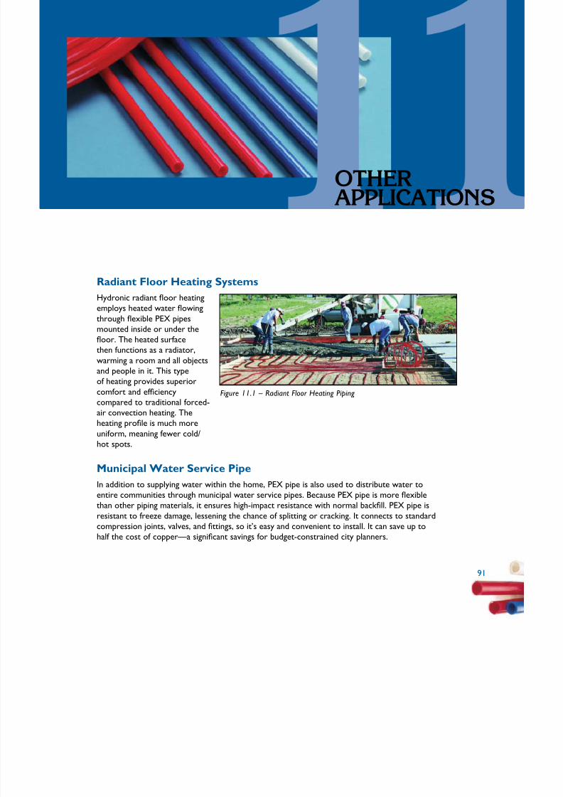
5/11/2018 Pex Design Guide - slidepdf.com
http://slidepdf.com/reader/full/pex-design-guide-55a0d1ab10986 101/128
9
oTHErAPPLICATIonS
Radiant Floor Heating SystemsHydronic radiant oor heating
employs heated water owing
through exible PEX pipes
mounted inside or under theoor. The heated surface
then functions as a radiator,
warming a room and all objectsand people in it. This typeof heating provides superiorcomfort and efciency Figure 11.1 – Radiant Floor Heating Piping compared to traditional forced-air convection heating. Theheating prole is much more
uniform, meaning fewer cold/hot spots.
Municipal Water Service Pipe
In addition to supplying water within the home, PEX pipe is also used to distribute water toentire communities through municipal water service pipes. Because PEX pipe is more exible
than other piping materials, it ensures high-impact resistance with normal backll. PEX pipe is
resistant to freeze damage, lessening the chance of splitting or cracking. It connects to standardcompression joints, valves, and ttings, so it’s easy and convenient to install. It can save up to
half the cost of copper—a signicant savings for budget-constrained city planners.
9

5/11/2018 Pex Design Guide - slidepdf.com
http://slidepdf.com/reader/full/pex-design-guide-55a0d1ab10986 102/128
92
Chapte 11 – oTHEr APPLICATIonS
Snow and Ice MeltPEX pipe can be used to create a hydronic system designedto augment the removal of snow and ice by circulating a heattransfer uid (usually antifreeze and water) through pipes installed
within outdoor surfaces. Common applications are for driveways,
sidewalks, hospital entrances, parking garage ramps, wheelchairramps, car washes, hot tub/pool surrounds, and runways. Benets
include reduced maintenance costs, no snow removal costs,
reduced liability, and obvious convenience.
Figure 11.2 – Snow and Ice Melt Piping
for a Driveway
Turf Conditioning
PEX pipe is installed within the soil layer of the turf and uid is
circulated at varying temperatures to gently warm the roots toprovide optimal root zone temperature. PEX pipe can extendthe growing season of natural grass surfaces in applications such
as golf courses and other sports eld surfaces. Similar systems
are also used in greenhouse applications with bedding plants andother foliage.
Figure 11.3 – Turf Conditioning in a Stadium
92

5/11/2018 Pex Design Guide - slidepdf.com
http://slidepdf.com/reader/full/pex-design-guide-55a0d1ab10986 103/128
9
Chapte 11 – oTHEr APPLICATIon
Fire Suppression UL-approved PEX piping and tting systems can be used to supply
water to re suppression sprinklers for residential applications.
While many sprinkler systems are largely independent from the
water distribution system, for some building types they can be
combined with a building’s cold-water plumbing system. This hasthe potential to reduce the installation costs. Sprinklers, PEXpiping, and ttings must comply with National Fire Protection
Association (NFPA) requirements for residential re sprinkler
systems, and local codes should be consulted when implementing Figure 11.4 – Fire Sprinkler withany re suppression system to ensure that PEX and/or combined PEX Piping
systems are permitted for your building type.
9

5/11/2018 Pex Design Guide - slidepdf.com
http://slidepdf.com/reader/full/pex-design-guide-55a0d1ab10986 104/128
94
Chapte 11 – oTHEr APPLICATIonS
94

5/11/2018 Pex Design Guide - slidepdf.com
http://slidepdf.com/reader/full/pex-design-guide-55a0d1ab10986 105/128
9
Appeix
PErForMAnCTEST SETuPAnd dATA
Diagrams of piping layouts for different test runs.
Figure A.1 – Water System Test Piping Layout – Trunk and Branch, 60’ to TF
95

5/11/2018 Pex Design Guide - slidepdf.com
http://slidepdf.com/reader/full/pex-design-guide-55a0d1ab10986 106/128
96
Appeix A – PErForMAnCE TEST SETuP And dATA
Figure A.2 – Water System Test Piping
Layout – Trunk and Branch, 100’ to TF
Figure A.3 – Water System Test Piping
Layout – Home-Run,60’ to TF
96

5/11/2018 Pex Design Guide - slidepdf.com
http://slidepdf.com/reader/full/pex-design-guide-55a0d1ab10986 107/128
9
Appeix A – PErForMAnCE TEST SETuP And dAT
Figure A.4 – Water
System Test Piping Layout – Home-Run,
100’ to TF
Figure A.5 – Water
System Test Piping Layout – Remote
Manifolds, 60’ to TF
9

5/11/2018 Pex Design Guide - slidepdf.com
http://slidepdf.com/reader/full/pex-design-guide-55a0d1ab10986 108/128
98
it
it
i
i
Fi
ipi
i l
Appeix A – PErForMAnCE TEST SETuP And dATA
Table A.1 – Simultaneous Flow Performance Data – 100’ Maximum Length, 60 and 80 psi Source Pressure
Fixture Flow
Total
SystemFlow
Cold
SupplyFlow
Hot
SupplyFlow
Main
Pressure
Test Fixture (Shower)
Hot FlowHot
Pres.Cold Flow Cold Pres.
gpm gpm gpm psi gpm psi gpm psi
Trunk and Branch
100’60 psi Static
0.0 0.0 0.0 60.0 0.0 54.3 0.0 55.4
TF 2.5 0.5 2.1 60.0 2.2 50.0 0.3 55.2
TF+Lav 4.3 1.8 2.5 60.0 2.2 49.1 0.3 53.5
TF+WC 6.8 4.6 2.2 60.0 2.2 50.1 0.2 46.5
TF+K 4.3 1.5 2.8 60.0 2.2 49.2 0.3 54.9
TF+Sh2 5.2 1.6 3.6 60.0 2.1 47.9 0.3 54.8
TF+Sh2+K 6.9 2.7 4.2 60.0 2.1 47.4 0.3 54.5
TF+Sh2+K t+Lav 8.6 4.2 4.4 60.0 2.1 47.1 0.3 52.1
TF+Sh2+K t+Lav+WC 12.5 7.2 5.3 60.0 2.1 44.4 0.2 44.5
gure A.6 – Water
System Test P ng Layout – Remote
Man fo ds, 100’ to TF

5/11/2018 Pex Design Guide - slidepdf.com
http://slidepdf.com/reader/full/pex-design-guide-55a0d1ab10986 109/128
9
Appeix A – PErForMAnCE TEST SETuP And dAT
Table A.1 – Simultaneous Flow Performance Data – 100’ Maximum Length, 60 and 80 psi Source Pressure (continued)
Fixture Flow
TotalSystem
Flow
ColdSupply
Flow
HotSupply
Flow
Main
Pressure
Test Fixture (Shower)
Hot Flow HotPres. Cold Flow Cold Pres.
gpm gpm gpm psi gpm psi gpm psi
Remote Manifold100’ 0.0 0.0 0.0 60.0 0.0 54.2 0.0 55.2
60 psi Static
TF 2.5 0.5 2.1 60.0 2.2 49.7 0.3 54.9
TF+Lav 4.l3 1.7 2.6 60.0 2.2 49.0 0.3 54.1
TF+WC 6.8 4.7 2.1 60.0 2.2 50.1 0.2 49.6
TF+Kit 4.3 1.6 2.7 60.0 2.2 49.1 0.3 54.8
TF+Sh2 5.2 1.7 3.5 60.0 2.2 48.4 0.3 54.7
TF+Sh2+Kit 6.9 2.8 4.0 60.0 2.1 47.9 0.3 54.3
TF+Sh2+Kit+Lav 8.6 4.2 4.4 60.0 2.1 47.2 0.3 53.1
TF+Sh2+Kit+Lav+WC 12.5 7.4 5.1 60.0 2.1 46.3 0.2 47.8
Home-Run 100’
60 psi Static0.0 0.0 0.0 60.0 0.0 54.1 0.0 55.1
TF 2.5 0.5 2.1 60.0 2.1 46.4 0.3 54.8
TF+Lav 4.3 1.5 2.8 60.0 2.1 46.3 0.3 54.7
TF+WC 6.8 4.6 2.1 60.0 2.1 47.1 0.3 54.6
TF+Kit 4.3 1.4 2.9 60.0 2.1 46.2 0.3 54.7
TF+Sh2 5.2 1.7 3.5 60.0 2.1 45.7 0.3 54.7
TF+Sh2+Kit 6.9 2.7 4.1 60.0 2.1 45.3 0.3 54.6
TF+Sh2+Kit+Lav 8.6 3.9 4.7 60.0 2.1 45.0 0.3 54.4
TF+Sh2+Kit+Lav+WC 12.5 7.7 4.8 60.0 2.1 45.6 0.3 53.9
Trunk and Branch100’ 0.0 0.0 0.0 80.0 0.0 74.5 0.0 75.4
80 psi Static
TF 2.9 0.4 2.5 80.0 2.6 68.7 0.3 75.1
TF+Lav 5.0 2.0 3.0 80.0 2.6 67.9 0.3 73.0
TF+WC 7.8 5.5 2.3 80.0 2.6 69.4 0.3 62.4
TF+Kit 5.0 1.7 3.3 80.0 2.6 68.5 0.3 75.0
9

5/11/2018 Pex Design Guide - slidepdf.com
http://slidepdf.com/reader/full/pex-design-guide-55a0d1ab10986 110/128
100
Appeix A – PErForMAnCE TEST SETuP And dATA
it
i
i
it
it
i
i
it
it
i
i
i l i ; l l il l i ; = Ki i iti l i
l l l i
( i )
Table A.1 – Simultaneous Flow Performance Data – 100’ Maximum Length, 60 and 80 psi Source Pressure
Fixture Flow
TotalSystem
Flow
ColdSupply
Flow
HotSupply
Flow
Main
Pressure
Test Fixture (Shower)
Hot Flow HotPres. Cold Flow Cold Pres.
gpm gpm gpm psi gpm psi gpm psi
TF+Sh2 6.0 1.8 4.1 80.0 2.6 67.9 0.3 74.8
TF+Sh2+K 7.9 2.9 5.0 80.0 2.5 66.3 0.3 74.3
TF+Sh2+K t+Lav 9.9 4.8 5.2 80.0 2.5 65.2 0.3 71.3
TF+Sh2+K t+Lav+WC 14.4 8.3 6.1 80.0 2.4 61.6 0.3 60.9
Remote Manifold
100’
80 psi Static
0.0 0.0 0.0 80.0 0.0 74.6 0.0 75.4
TF 2.9 0.5 2.4 80.0 2.6 68.7 0.3 75.1
TF+Lav 5.0 1.9 3.1 80.0 2.5 67.3 0.3 74.0
TF+WC 7.8 5.5 2.3 80.0 2.6 68.9 0.3 67.6
TF+K 5.0 1.7 3.2 80.0 2.6 68.2 0.3 74.8
TF+Sh2 6.0 1.8 4.1 80.0 2.5 67.2 0.3 74.8
TF+Sh2+K 7.9 34.1 4.8 80.0 2.5 65.9 0.3 74.5
TF+Sh2+K t+Lav 9.9 4.8 5.1 80.0 2.5 65.0 0.3 72.7
TF+Sh2+K t+Lav+WC 14.4 8.6 5.8 80.0 2.5 63.0 0.3 65.0
Home-Run
100’80 psi Static
0.0 0.0 0.0 80.0 0.0 74.5 0.0 75.3
TF 2.9 0.4 2.5 80.0 2.5 63.6 0.3 75.0
TF+Lav 5.0 1.7 3.3 80.0 2.5 63.3 0.3 74.8
TF+WC 7.8 5.3 2.6 80.0 2.5 64.4 0.3 74.6
TF+K 5.0 1.7 3.3 80.0 2.5 63.4 0.3 74.8
TF+Sh2 6.0 1.7 4.2 80.0 2.5 62.6 0.3 74.8
TF+Sh2+K 7.9 3.0 4.9 80.0 2.4 62.0 0.3 74.7
TF+Sh2+K t+Lav 9.9 4.5 5.4 80.0 2.4 61.5 0.3 74.5
TF+Sh2+K t+Lav+WC 14.4 8.9 5.5 80.0 2.4 62.0 0.3 73.8
TF = Test Shower F xture, 15’ e evat on Lav = Lavatory, both va ves open, 15’ e evat on WC = Water C oset, tank type, 15’ e evat on Kit tchen, m d-pos on, 4’ e evat on
Sh2 = 2nd Shower, fu l open va ve, 5’ e evat on
cont nued
100

5/11/2018 Pex Design Guide - slidepdf.com
http://slidepdf.com/reader/full/pex-design-guide-55a0d1ab10986 111/128
10
Appeix A – PErForMAnCE TEST SETuP And dAT
Table A.2 – Simultaneous Flow Performance Data – 60’ Maximum Length, 60 and 80 psi Source Pressure
Fixture Flow
TotalSystem
Flow
ColdSupply
Flow
HotSupply
Flow
Main
Pressure
Test Fixture (Shower)
Hot Flow HotPres. Cold Flow Cold Pres.
gpm gpm gpm psi gpm psi gpm psi
Trunk and Branch60’ 0.0 0.0 0.0 60.0 0.0 54.2 0.0 55.1
60 psi Static
TF 2.5 0.5 2.1 60.0 2.2 50.8 0.3 54.9
TF+Lav 4.3 1.8 2.5 60.0 2.2 49.9 0.3 53.7
TF+WC 6.8 4.7 2.1 60.0 2.2 50.8 0.2 46.5
TF+Kit 4.3 1.4 3.0 60.0 2.2 49.9 0.3 48.6
TF+Sh2 5.2 1.6 3.5 60.0 2.2 48.7 0.3 54.7
TF+Sh2+Kit 6.9 2.7 4.2 60.0 2.1 48.0 0.3 54.5
TF+Sh2+Kit+Lav 8.6 4.2 4.4 60.0 2.1 47.7 0.3 52.4
TF+Sh2+Kit+Lav+WC 12.5 7.3 5.2 60.0 2.1 46.0 0.2 46.5
Remote Manifold
60’ 0.0 0.0 0.0 60.0 0.0 54.0 0.0 55.2
60 psi Static
TF 2.5 0.5 2.0 60.0 2.2 50.6 0.3 55.0
TF+Lav 4.3 1.7 2.6 60.0 2.2 50.1 0.3 54.5
TF+WC 6.8 4.7 2.1 60.0 2.2 50.9 0.3 51.7
TF+Kit 4.3 1.7 2.7 60.0 2.2 50.2 0.3 54.8
TF+Sh2 5.2 1.6 3.6 60.0 2.2 49.2 0.3 54.7
TF+Sh2+Kit 6.9 2.7 4.2 60.0 2.2 48.5 0.3 54.4
TF+Sh2+Kit+Lav 8.6 4.1 4.5 60.0 2.1 48.0 0.3 53.5
TF+Sh2+Kit+Lav+WC 12.5 7.5 5.0 60.0 2.1 47.4 0.2 49.7
Home-Run 60’60 psi Static
0.0 0.0 0.0 60.0 0.0 27.6 0.0 28.5
TF 2.5 0.5 2.0 60.0 2.2 48.8 0.3 54.9
TF+Lav 4.3 1.5 2.8 60.0 2.2 48.6 0.3 54.8
TF+WC 6.8 4.8 2.0 60.0 2.2 49.3 0.3 54.6
10
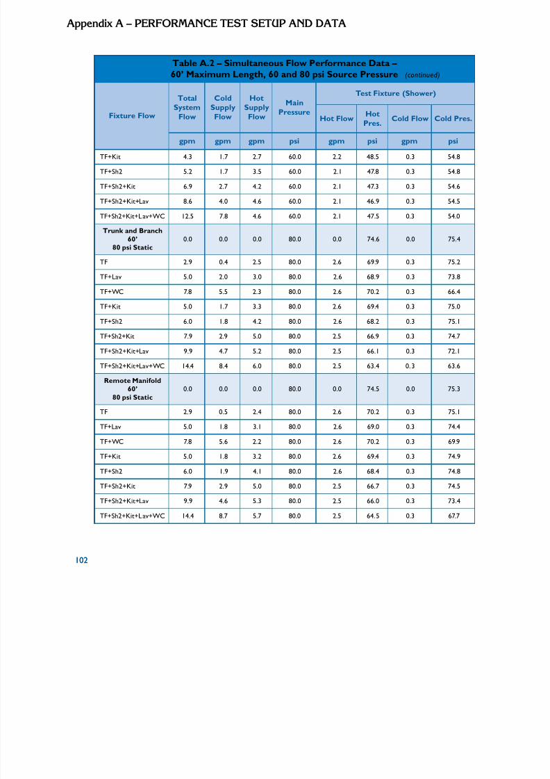
5/11/2018 Pex Design Guide - slidepdf.com
http://slidepdf.com/reader/full/pex-design-guide-55a0d1ab10986 112/128
102
Appeix A – PErForMAnCE TEST SETuP And dATA
Table A.2 – Simultaneous Flow Performance Data – 60’ Maximum Length, 60 and 80 psi Source Pressure (continued)
Fixture Flow
TotalSystem
Flow
ColdSupply
Flow
HotSupply
Flow
Main
Pressure
Test Fixture (Shower)
Hot Flow HotPres. Cold Flow Cold Pres.
gpm gpm gpm psi gpm psi gpm psi
TF+Kit 4.3 1.7 2.7 60.0 2.2 48.5 0.3 54.8
TF+Sh2 5.2 1.7 3.5 60.0 2.1 47.8 0.3 54.8
TF+Sh2+Kit 6.9 2.7 4.2 60.0 2.1 47.3 0.3 54.6
TF+Sh2+Kit+Lav 8.6 4.0 4.6 60.0 2.1 46.9 0.3 54.5
TF+Sh2+Kit+Lav+WC 12.5 7.8 4.6 60.0 2.1 47.5 0.3 54.0
Trunk and Branch
60’ 0.0 0.0 0.0 80.0 0.0 74.6 0.0 75.480 psi Static
TF 2.9 0.4 2.5 80.0 2.6 69.9 0.3 75.2
TF+Lav 5.0 2.0 3.0 80.0 2.6 68.9 0.3 73.8
TF+WC 7.8 5.5 2.3 80.0 2.6 70.2 0.3 66.4
TF+Kit 5.0 1.7 3.3 80.0 2.6 69.4 0.3 75.0
TF+Sh2 6.0 1.8 4.2 80.0 2.6 68.2 0.3 75.1
TF+Sh2+Kit 7.9 2.9 5.0 80.0 2.5 66.9 0.3 74.7
TF+Sh2+Kit+Lav 9.9 4.7 5.2 80.0 2.5 66.1 0.3 72.1
TF+Sh2+Kit+Lav+WC 14.4 8.4 6.0 80.0 2.5 63.4 0.3 63.6
Remote Manifold60’ 0.0 0.0 0.0 80.0 0.0 74.5 0.0 75.3
80 psi Static
TF 2.9 0.5 2.4 80.0 2.6 70.2 0.3 75.1
TF+Lav 5.0 1.8 3.1 80.0 2.6 69.0 0.3 74.4
TF+WC 7.8 5.6 2.2 80.0 2.6 70.2 0.3 69.9
TF+Kit 5.0 1.8 3.2 80.0 2.6 69.4 0.3 74.9
TF+Sh2 6.0 1.9 4.1 80.0 2.6 68.4 0.3 74.8
TF+Sh2+Kit 7.9 2.9 5.0 80.0 2.5 66.7 0.3 74.5
TF+Sh2+Kit+Lav 9.9 4.6 5.3 80.0 2.5 66.0 0.3 73.4
TF+Sh2+Kit+Lav+WC 14.4 8.7 5.7 80.0 2.5 64.5 0.3 67.7
102

5/11/2018 Pex Design Guide - slidepdf.com
http://slidepdf.com/reader/full/pex-design-guide-55a0d1ab10986 113/128
10
Appeix A – PErForMAnCE TEST SETuP And dAT
Table A.2 – Simultaneous Flow Performance Data – 60’ Maximum Length, 60 and 80 psi Source Pressure (continued)
Fixture Flow
TotalSystem
Flow
ColdSupply
Flow
HotSupply
Flow
Main
Pressure
Test Fixture (Shower)
Hot Flow HotPres. Cold Flow Cold Pres.
gpm gpm gpm psi gpm psi gpm psi
Home-Run 60’
80 psi Static0.0 0.0 0.0 80.0 0.0 74.5 0.0 75.3
TF 2.9 0.5 2.4 80.0 2.5 66.9 0.3 75.1
TF+Lav 5.0 1.6 3.4 80.0 2.5 66.3 0.3 75.0
TF+WC 7.8 5.4 2.5 80.0 2.5 67.3 0.3 74.7
TF+Kit 5.0 1.6 3.4 80.0 2.5 66.4 0.3 74.9
TF+Sh2 6.0 1.8 4.2 80.0 2.5 65.8 0.3 75.0
TF+Sh2+Kit 7.9 2.9 5.0 80.0 2.5 64.8 0.3 74.8
TF+Sh2+Kit+Lav 9.9 4.5 5.5 80.0 2.5 63.8 0.3 74.6
TF+Sh2+Kit+Lav+WC 14.4 9.0 5.4 80.0 2.5 64.2 0.3 73.9
TF = Test Shower Fixture, 15’ elevation; Lav = Lavatory, both valves open, 15’ elevation
WC = Water Closet, tank type, 15’ elevation; Kit = Kitchen, mid-position, 4’ elevationSh2 = 2nd Shower, full open valve, 5’ elevation
10

5/11/2018 Pex Design Guide - slidepdf.com
http://slidepdf.com/reader/full/pex-design-guide-55a0d1ab10986 114/128
104
Appeix A – PErForMAnCE TEST SETuP And dATA
104

5/11/2018 Pex Design Guide - slidepdf.com
http://slidepdf.com/reader/full/pex-design-guide-55a0d1ab10986 115/128
10
Appeix
InSTALLATIonCHECKLIST
q l
q l i ini
q i ipi
q imi
q l i
q Pl ipi i
q Pl i l l iq i i
q in pipi ll ll i i i
q i ls
q i i
q l i
q i i
q i i i l l i li le)
DESIGN
Consu t Local Codes
Se ect P pe and Jo ng System
Des gn P ng System
Opt ze Home Layout
Se ect Appropr ate System
an P ng Rout ng
an Man fo d and Va ve Locat onsEst mate Mater al and Order
TRAINING
Tra ng insta ers on insta at on techn ques and tt ngs
Order or rent tt ng too
INSTALLATION
Rece ve mater al and store as recommended by manufacturer
Insta l per manufacturer recommendat ons
Pressure test per manufacturer recommendat ons and code requ rements
FOLLOW UP
Instruct homeowner on locat on and operat on of man fo d va ves ( f app cab
10

5/11/2018 Pex Design Guide - slidepdf.com
http://slidepdf.com/reader/full/pex-design-guide-55a0d1ab10986 116/128
106
Appeix B – InSTALLATIon CHECKLIST
106

5/11/2018 Pex Design Guide - slidepdf.com
http://slidepdf.com/reader/full/pex-design-guide-55a0d1ab10986 117/128
10
Appeix
rESourCES
Articles and Reports
1. Automated Builder Magazine, “PEX Pipe Gains Popularity for PracticalPurposes.” April 2005, page 40. This article presents the multitude of advantages tousing PEX plumbing water supply systems in residential construction, and discusses
the standards and certications required for PEX pipe and ttings. One home builder’s
experience with PEX and a manifold system is described.
2. Couch, Toro, Oliphant and Vibien, Chlorine Resistance Testing of UV Exposed
Pipe, Jana Laboratories, Ontario, Canada, 2002. Chlorine Resistance (CR) testing isused to determine the impact of accelerated UV exposure on the oxidative resistance
of cross-linked polyethylene (PEX) pipe. Following accelerated UV exposure, sampleswere tested to failure under accelerated test conditions to simulate chlorinated
potable water. For the particular material examined, it was demonstrated thatexcellent retention of oxidative stability was achieved when suitable UV protection wasemployed.
3. Kempton, William, “Residential Hot Water: A Behaviorally-DrivenSystem,” Energy , Volume 13, Number 1, January 1988, pages 107-114. This articlereports on the results of monitoring the hot water use in seven homes over 7-18
months. The study shows the wide variation in hot water use among the differentproject participants. For instance, water consumption ranged from 44.5 liters per dayper person to 126.4 liters per day per person. Bathing comprised the largest single
water use in all homes but duration and volume varied signicantly. The study pointsto the potential for water and energy savings through modication of behavior but also
notes that habits related to hot water usage have deep roots in personal, social, andcultural values. The study also found that most of the participants had misperceptions
related to the duration and amount of their water usage and did not have a rm
understanding of the costs of hot water.
10
5/11/2018 Pex Design Guide - slidepdf.com
http://slidepdf.com/reader/full/pex-design-guide-55a0d1ab10986 118/128
108
l
l iil i i l
l i i l iscipli i i
4. Korman, Thomas M. et al, Knowledge and Reasoning for MEP Coordination,
Journal of Construction and Engineering Management, Vo ume 129 Number 6,
November-December 2003, pp. 627-634. “Current y, des gners and constructorsuse ta ored CAD systems to des gn and fabr cate MEP systems, but no know edge-based computer techno ogy ex sts to ass st in the mu tid ne MEP coord nat on
Appeix C – rESourCES
effort. The paper describes results from a research project to capture knowledge
related to design criteria, construction, operations, and maintenance of MEP systemsand apply this knowledge in a computer tool that can assist designers and builders inresolving coordination problems for multiple MEP systems.” This work might providebackground information relevant to developing a knowledge-based design tool for
residential plumbing distribution systems.
5. NSF International, Frequently Asked Questions on Health Effects of PEX
Tubing. This article explains who NSF International is, provides information on NSF
Listed Products for potable water applications, and describes applicable NSF/ANSIstandards for testing and evaluation of potable plumbing.
6. Okajima, Toshio, Computerized Mechanical and Plumbing Design, Actual
Specifying Engineer, Volume 33 Number 6, June 1975, pp. 78-83. “Many mechanicaland plumbing systems designs are based on the engineer’s past experience or educatedguesses. The author tells how one rm developed a computer program for plumbing
and heating, ventilating, and air conditioning design.”
7. Orloski, M.J. and Wyly, R.S., Performance Criteria and Plumbing System
Design, National Engineering Lab, Washington, D.C., 1978. “An overview is presented
indicating how the performance approach to plumbing system design can be usedto extend traditional methods to innovative systems. …Some of the mathematicalmodels now used for system design and pipe sizing in plumbing codes are reviewed inthe context of performance-oriented research. … Conceivably the re-examination
by plumbing designers of traditional design criteria against measured user needs couldbe benecially extended to other areas of plumbing design such as water distribution,
storm drainage, and plumbing xtures. Beyond this, it has been recognized that
uniform guidelines for evaluation of innovative systems, based on research ndings, are
essential for wide acceptance of performance methods, particularly by the regulatorycommunity.
8. Rubeiz, Camille, “Flexing Your PEX: Plumbing the Possibilities of Crosslinked Polyethylene Pipes,” Modern Materials, Vol. 2, No. 2, November 2004,pages 5-8. Properties of PEX pipe are described, as well as benets of using PEX for
potable water supply plumbing systems. Parallel piping and central manifold system
installations are discussed. Real and misconceived limitations are also presented. Inaddition, other applications for PEX pipe systems, such as snow and ice melt and turf conditioning are mentioned.
9. Rubeiz, Camille & Ball, Michael, “Warming Up to PEX Pipe RadiantHeating Systems,” Modern Materials, Vol. 2 No. 1, May 2004, pages 14-18. Thearticle describes how radiant heating works, and compares the radiant heat distribution
to traditional baseboard or forced air systems. There is a general description of thethree methods of cross-linking polyethylene to form PEX piping (radiation, peroxide,
108

5/11/2018 Pex Design Guide - slidepdf.com
http://slidepdf.com/reader/full/pex-design-guide-55a0d1ab10986 119/128
10
il li l i i i
i i i i ll icl i i ll i
i i i i li
j
and s ane processes). App cab e ASTM and CSA standard spec cat ons for test ng of
PEX p pe and tt ngs are l sted. F na y, the art e br ey d scusses the insta at on of
PEX rad ant heat ng systems in new resident al construct on or remode ng projects.
10. Steele, Alfred, “Plumbing Design Has Ma or Impact on Energy
Appeix C – rESourCE
Consumption,” Specifying Engineer, Volume 45, Number 6, June 1981, pages 8083. The paper discusses the potential energy savings that could result from low-ow
xtures, pipe insulation, and water heater temperature settings. The author emphasizes
that signicant water savings and therefore, energy savings as well could be achieved
with no inconvenience to the end-user. It was not until 1994 that the rst low-ow
xtures were introduced in the United States after being federally mandated.
11. Stewart, William E. et al, Evaluation of Service Hot Water Distribution system
Losses in Residential and Commercial Installations: Part 1 – Field/LaboratoryExperiments and Simulation Model and Part 2 – Simulations and Design Practices,
ASHRAE Transactions, Volume 105, 1999. The papers describe a numerical modeldeveloped to estimate the heat loss or gain from insulated and uninsulated, copper and
steel hot water pipes. The authors contend that the simulation model is a more reliableand consistent method of estimating such losses due to the difculty of accurately
measuring small temperature differences in eld and laboratory experiments. The
results of the simulation model correlate closely with previously published data,specically 1997 ASHRAE Handbook – Fundamentals and 1995 ASHRAE Handbook
– HVAC Applications. The simulation results showed more than a 50 percent decreasein heat loss in hot water piping that was insulated within approximately three feet of the water heater and that increasing the length of pipe insulated does not signicantly
decrease heat loss further.
12. Tao, William & Associates, “Plumbing System Design,” Heating, Piping, &
Air Conditioning, Volume 59 Number 3, March 1987, pp. 101-114. This article outlines
the fundamental criteria to be considered in the design of a building plumbing system.These criteria include load calculations, system sizing, and special design applications.A procedure for plumbing system design is also introduced that may serve as acomprehensive basis for developing computer aided design programs.
13. Vibien, Couch, Oliphant et al, Assessing Material Performance in Chlorinated
Potable Water Applications, Jana Laboratories, Ontario, Canada. In this study, thenature of the failure mechanism of cross-linked polyethylene (PEX) pipe material
exposed in the laboratory to chlorinated potable water was examined. Based on thisstudy, the PEX pipe material appears to have good resistance to chlorinated potablewater.
14. Wendt, R.L., Evelyn Baskin, David Durfee, Evaluation of Residential Hot
Water Distribution Systems by Numeric Simulation, Buildings Technology Center,Oak Ridge National Laboratory for the California Energy Commission, Oak Ridge,
TN, 2004. This study simulated and compared the energy and water performance,economics, and barriers to use of various domestic hot water distribution systems inCalifornia homes. Variation in systems included trunk and branch, manifold systems,copper pipe, CPVC pipe, PEX piping, insulated and uninsulated pipe, attic location, slab
10

5/11/2018 Pex Design Guide - slidepdf.com
http://slidepdf.com/reader/full/pex-design-guide-55a0d1ab10986 120/128
110
l i i l i i i l i i l,i ll i l l
i l i ipil
ocat on, demand rec rcu at on, and cont nuous rec rcu at on. Us ng a computer modeLabV ew, the fo ow ng resu ts were found for a c ustered hot water usage pattern:
a. Demand rec rcu at on systems, whether p ng was copper or CPVC, wasted theeast water and the least energy.
Appeix C – rESourCES
b. Whether copper or CPVC piping was used, the system with a centrally located
water heater was second with respect to the least amount of energy wasted.However, almost twice as much water was wasted in comparison to therecirculation systems even though the water heater was centrally located.
c. In both groups, the CPVC systems were slightly better energy performers than theircopper counterparts – about 4 to 14 percent better.
d. The parallel pipe congurations using PEX tubing wasted about 3 percent more
energy than uninsulated copper pipe in an attic installation, but wasted 60 percentless energy than uninsulated copper installed in a slab. Insulating the sub-slab copperpipe brought its energy performance inline with the PEX system. With respect to
water waste, the parallel system (attic installation) performed similarly to copperpipe installed in an attic.
e. Sub-slab installation without insulation compromised the energy and water
performance of all the systems. However, the parallel system using PEX pipe sufferedthe least – an approximate 30 percent drop in performance compared to a fourfolddecrease for the copper and CPVC systems.
f. Construction costs for the parallel system using PEX tubing were slightly lower thanthe trunk and branch system using copper, but higher than the CPVC systems.
While the study indicates that usage patterns have the most signicant effect upon
energy usage and water consumption in residential situations, it also postulates that“parallel pipe distribution systems may offer an attractive alternative for some housedesigns and distribution system layouts.” The modeling showed very little difference
in energy and water performance when clustered use was assumed but indicated thatparallel systems outperform conventional trunk and branch systems when cold startsare typical.
15. Wiehagen, J. and Sikora, J. (March 2003). Performance Comparison of
Residential Hot Water Systems, work performed by NAHB Research Center, Inc.for NREL. Using data from two research sites in Ohio and from weekly laboratoryexperimental data, a simulation model was developed to estimate annual energy
consumption for several types of water-heating systems. Using the Transient EnergySystem Simulation Tool, TRNSYS, three types of systems were analyzed under high-usage (average 76 gallons per day) and low-usage conditions (average 28 gallons per
day). The systems were 1) a standard electric storage tank water heater with a copper
tree-conguration distribution system, 2) a central tankless water heater with apolyethylene (PEX) piping parallel distribution system, and 3) multiple point-of-usewater heaters with a copper tree-type distribution system. The simulations showed
a 12 percent increase in overall system efciency for the tankless water heater with
the PEX parallel piping system compared to the storage heater with the copper treedsystem under high usage conditions. For the low-use home, there was a 26 percent
110

5/11/2018 Pex Design Guide - slidepdf.com
http://slidepdf.com/reader/full/pex-design-guide-55a0d1ab10986 121/128
11
i i l is al i i
ll ipi i i i
i l i ii l i i
ltipl i l i
ncrease in efc ency for the same system. The ana ys so ind cated energy sav ngs
for the PEX para el p ng congurat on whether the water heat ng equ pment was
a convent onal tank or a tank ess system – 6 percent sav ngs for the h gh-use homeand 13 percent sav ngs for the low-use home. Ana ys s of the tree-type system w thmu e po nt-of-use heaters a so showed improved energy performance in compar son
Appeix C – rESourCE
to a similar treed distribution system with a storage tank water heater – a 50 percent
reduction in energy consumption for the low-use condition and 28 percent reductionfor the high-use home. In addition to the energy savings, an economic analysis showeda positive annual cash ow for the parallel distribution systems whether a tank or
tankless heater was used compared to the standard tank/tree system. The analysis
included estimates of installed cost, nancing costs, and electricity costs.
16. Wiehagen, J. and Sikora, J. (April, 2002). Domestic Hot Water System
Modeling for the Design of Energy Efcient Systems, work performed by NAHB
Research Center, Inc. for NREL. Using data obtained from actual home sites, theresearchers developed a computer simulation model to analyze typical residentialplumbing systems. The evaluation compared demand water heating equipment in
conjunction with various piping congurations to a standard tank heater with a tree
delivery system. High- and low-usage patterns were considered. Maximum energysavings resulted from using a combination of a centrally located demand water heaterwith a parallel piping system. Annual energy savings were 17 percent for the high
consumption home and 35 percent for the low use home. The demand system didshow some hot water temperature degradation during periods of high ow rates.
17. Wyly, R.S. et al, (May 1975). “Review of Standards and Other Information
on Thermoplastic Piping in Residential Plumbing.” Sponsored by the U.S.Department of Housing and Urban Development, Washington, D.C. “The paperis a review of existing information on the physical characteristics of thermoplastic
piping that are of particular interest in considering its potential for use in residentialabove-ground plumbing. The presentation is oriented to considerations of adequacy
of functional performance of plumbing systems from the user’s/owner’s viewpoint incontrast with the typical product-specications oriented format reected in current
standards. Not only are the physical characteristics emphasized that relate mostdirectly to the determination of functional performance of installed systems, but theimportance of design and installation detail in the context is discussed. In conclusion,this review indicates the need for better use of existing knowledge as well as for some
research and test development work particularly in the areas of thermal properties,response to building res, and resistance to water hammer.”
Manufacturers’ Information
1. IPEX, Inc., PlumbBetter – IPEX Piping Systems Installation Guide, Denver,CO. The guide provides installation guidelines and product specications regarding
thermal expansion, bending radius, cutting and joining instructions, restop ratings, and
pressure drop and ow rate specications. The document does not give guidance on
system design or layout, specically stating that “the method of plumbing a residence or
commercial project is left to the discretion of the designer, contractor, or developer.”
11

5/11/2018 Pex Design Guide - slidepdf.com
http://slidepdf.com/reader/full/pex-design-guide-55a0d1ab10986 122/128
112
i li il i
izi l i i i i i i ll i i i irl i i
li i l i ial
2. REHAU, Inc. (2004). REHAU PEX Plumbing Systems – Technical Manual
855.620, Leesburg, VA. REHAU’s Techn cal Manual out nes a deta ed des gn
procedure for s ng a p umb ng d str but on system. Th s procedure is most l ke y to beused by p umb ng des gn eng neers or fa y soph st cated trade contractors for larger,more comp cated projects. It is not l ke y to be used by the major ty of resident
Appeix C – rESourCES
plumbing contractors or builders. The procedure described here could be used to
develop a more straightforward and user-friendly tool that would identify the optimumdistribution system design for a given situation.
3. Uponor Wirsbo, Inc. (1993). Aquapex Professional Plumbing Installation
Guide, Apple Valley, MN. Wirsbo’s installation guide gives detailed instruction aboutinstallation of PEX tubing and manifolds, instructions for various types of connectionsand required supports, and recommended distances from heat sources such as ues
or recessed light xtures. The guide does show the different options for system design
including home-run, remote manifolds, modied home-run, and run-and-branch
systems. General advantages and limitations of the different systems are identied. The
guidance remains general except for a reference to a distance of approximately 12 to
15 feet from a central manifold as the maximum recommended for a home-run layout.
Demand or timed re-circulation is also mentioned as an energy and water saving designfeature. Wirsbo provides a detailed design and installation guide for their D’mand HotWater Delivery System.
4. Vanguard Piping Systems, Inc. (2005). Manabloc – Modular Manifold
Plumbing System for Use with Vanguard Vanex® SDR9 Cross-Linked
Polyethylene Tubing, McPherson, KS. This manual offers general design guidance for
parallel distribution systems using cross-linked polyethylene tubing. However, it doesnot provide sufciently specic information to allow a contractor to size and lay out
a distribution system for an entire project. Examples of the type of guidance given
include:
• Typical supply line size per number of bathrooms;
• Typical distribution line size per xture ow requirement;
• Use of multiple manifolds when the home is large or there are a large number of xtures.
Understandably, the Manabloc manufacturer does not discuss advantages anddisadvantages of a parallel vs. tree distribution systems under different circumstances.
5. Viega North America, Pure Flow Water Systems – Installation Manual, Bedford,MA. The manual provides detailed instructions for the installation of their Pexceland FostaPEX tubing. They outline different design and layout strategies in a generalmanner. The manual also gives pressure drop information for their materials that could
be used to develop more specic design tools.6. Zurn Industries, Inc., PEX Plumbing Design and Application Guide, Zurn
Industries, Inc., Erie, PA. The Zurn Guide offers similar installation instructions to
the other manufacturers. Each manufacturer recommends their specic crimp tool
and gauge. In addition to guidance regarding thermal expansion, protection fromdamage, pressure drop, and ow rate, the Zurn manual also discusses sizing and
112

5/11/2018 Pex Design Guide - slidepdf.com
http://slidepdf.com/reader/full/pex-design-guide-55a0d1ab10986 123/128
11
l i i l ll ipi i i i il i li i / i i i
ibl it ti i / i i lli l i
ocat ng man fo ds for para el p ng d str but on systems. Wh e deferr ng to locacode requ rements, Zurn does recommend us ng 3 8 nch tub ng for hot water l nes
whenever poss e to reduce wa me, stat ng that 3 8 nch tub ng is usua y adequatefor most s nk, lavatory, and shower xtures un ess the d stance is greater than 80 feet.
Appeix C – rESourCE
Plastics Pipe Institute (PPI) Technical Notes1. TN-17 (Feb. 1998). “Crosslinked Polyethylene (PEX) Tubing.” This technical
note provides general information on cross-linked polyethylene (PEX), such as: “Whatis PEX?” and “How does PEX improve properties of PE?” Three methods of cross-linking polyethylene to form PEX, qualication standards, and certication requirement
are presented. Finally, several applications for the use of PEX piping, and advantages of PEX pipe systems are listed.
2. TN-26 (2002). “Erosion Study on Brass Insert Fittings Used in PEX PipingSystems.” The objective of this test program was to subject different brass insertttings and different pipe diameters for PEX plumbing systems to ow rates that
represented the maximums that could occur if a plumbing system was sized according
to the 2000 Uniform Plumbing Code. Enough chlorinated water owed through thepipe and ttings equivalent to 40 years of service in a typical single family residence.
None of the brass ttings failed during the test. Weight losses were less than 3 percent
for all ttings. A test procedure is appended to this Technical Note.
3. TN-31 (2004). “Differences between PEX and PB Piping Systems for Potable Water Applications.” Several features and properties of PEX pipe arepresented to differentiate between PEX and PB. Mechanical ttings are tested and
certied to comply with higher standards for chlorine resistance and long-term
durability than were used for polybutylene pipe.
4. TN-32 (2004). “UV Labeling Guidelines for PEX Pipes.” These guidelines
present recommendations for exposure and storage of PEX piping, and an example of acautionary label to be applied to packaging to ensure that PEX is not over exposed tosunlight (UV radiation).
5. TN-33 (2004). “Standard Ultraviolet (UV) Radiation Exposure Methodfor Crosslinked Polyethylene (PEX) Tubing.” This is an industry consensusUV exposure test method that provides a denition of Total UV Energy per Monthly
Time Period, and requirements for PEX piping exposure. Reporting and recordingrequirements are also presented.
11

5/11/2018 Pex Design Guide - slidepdf.com
http://slidepdf.com/reader/full/pex-design-guide-55a0d1ab10986 124/128
114
Appeix C – rESourCES
114

5/11/2018 Pex Design Guide - slidepdf.com
http://slidepdf.com/reader/full/pex-design-guide-55a0d1ab10986 125/128
11
GLoSSArY
ASTM: American Society for Testing and Materials
Corrosion: deterioration in metals caused by oxidation or chemical action
Cross-linked polyethylene: a exible, “thermoset” plastic created using polymer technology
where the molecules of a high-density polyethylene (HDPE) base material are permanently
linked to each other by a process called cross-linking (PEX)
Elasticity: a measure of material stiffness or the ability of the material to stretch or deformtemporarily under a load
Fitting: a device or connection that allows the PEX pipe to change direction or size, such as a
tee, elbow, or coupling
Fixture: a device or appliance at the end of a water supply distribution pipe line. Example:lavatory, water closet, tub/shower, dishwasher
Home-run: a plumbing design that utilizes a central manifold and distribution piping to each
hot and cold water xture
IAPMO: International Association of Plumbing and Mechanical Ofcials
ICC: International Code Council
IPC: International Plumbing Code
IRC: International Residential Code
Joint: the connection of the PEX pipe to a tting, xture, or manifold
Manifold: a device having a series of ports that are used to connect distribution lines forseveral xtures
NSPC: National Standard Plumbing Code
11
5/11/2018 Pex Design Guide - slidepdf.com
http://slidepdf.com/reader/full/pex-design-guide-55a0d1ab10986 126/128
l i i l li i i
l i i l li
l i l l l i
GLoSSArY
Outlet: see xture
pH: a sca e rang ng from 0 to 14 that ranks how acid c or a ka ne a l quid is; water w th a pH
be ow 7 is considered acid c and water w th a pH above 7 is considered a ka ne
Polybutylene: a “thermop ast c” po ymer that was used for supp y water p umb ng fromabout 1978 to 1995. There were several reported failures; therefore, PB is no longer approved
for water supply piping (PB)
PPFA: Plastic Pipe and Fittings Association
PPI: Plastics Pipe Institute
Remote manifold: a plumbing system that uses trunk lines from the water source to small
manifolds at grouped xtures, such as a bathroom; can be ow-through or closed end
Scaling: process of mineral buildup on the interior of a pipe
Test xture: the tub-shower unit farthest from the water source that was instrumented to
measure ow rate, owing pressure, and mixed water temperature in the lab tests
Thermoplastic: having the property of becoming soft when heated and hard when cooled
Thermoset: having the property of becoming permanently hard and rigid when heated orcured
Trunk and branch: a plumbing design that has a large main line that feeds smaller pipes toeach xture
Ultraviolet: high energy light waves found in sunlight that lead to the degradation of many
plastics and materials (UV)
UPC: Uniform Plumbing Code
Wait time: the time it takes for hot water to be delivered to the Test Fixture; delivery time
Water hammer: a banging noise heard in a water pipe following an abrupt alteration of theow with resultant pressure surges
116

5/11/2018 Pex Design Guide - slidepdf.com
http://slidepdf.com/reader/full/pex-design-guide-55a0d1ab10986 127/128
1

5/11/2018 Pex Design Guide - slidepdf.com
http://slidepdf.com/reader/full/pex-design-guide-55a0d1ab10986 128/128