Petition for Inter Partes Review of Patent No. 6,091,940 ...€¦ · Petition for Inter Partes...
60
Petition for Inter Partes Review of Patent No. 6,091,940 UNITED STATES PATENT AND TRADEMARK OFFICE BEFORE THE PATENT TRIAL AND APPEAL BOARD Qualcomm Incorporated and Qualcomm Atheros, Inc. Petitioners v. ParkerVision, Inc. Patent Owner U.S. Patent No. 6,091,940 Filing Date: October 21, 1998 Issue Date: July 18, 2000 Title: Method and System for Frequency Up-Conversion Inter Partes Review No. ______ PETITION FOR INTER PARTES REVIEW OF U.S. PATENT NO. 6,091,940
-
Upload
nguyenminh -
Category
Documents
-
view
216 -
download
0
Transcript of Petition for Inter Partes Review of Patent No. 6,091,940 ...€¦ · Petition for Inter Partes...
Petition for Inter Partes Review of Patent No. 6,091,940
UNITED STATES PATENT AND TRADEMARK OFFICE
BEFORE THE PATENT TRIAL AND APPEAL BOARD
Qualcomm Incorporated and Qualcomm Atheros, Inc. Petitioners
v.
ParkerVision, Inc. Patent Owner
U.S. Patent No. 6,091,940
Filing Date: October 21, 1998 Issue Date: July 18, 2000
Title: Method and System for Frequency Up-Conversion
Inter Partes Review No. ______
PETITION FOR INTER PARTES REVIEW OF U.S. PATENT NO. 6,091,940

Table of Contents
-i-
I. INTRODUCTION ........................................................................................ 1
II. MANDATORY NOTICES UNDER 37 C.F.R. § 42.8(A)(1) .................... 2
A. Real Party-In-Interest Under 37 C.F.R. § 42.8(b)(1) ........................... 2
B. Related Matters Under 37 C.F.R. § 42.8(b)(2) .................................... 2
C. Lead and Back-Up Counsel under 37 C.F.R. § 42.8(b)(3) .................. 3
D. Service Information .............................................................................. 3
E. Power of Attorney ................................................................................ 3
III. PAYMENT OF FEES - 37 C.F.R. § 42.103 ................................................ 3
IV. REQUIREMENTS FOR INTER PARTES REVIEW UNDER 37 C.F.R. § 42.104 .............................................................................................. 4
A. Grounds for Standing Under 37 C.F.R. § 42.104(a) ............................ 4
B. Identification of Challenge Under 37 C.F.R. § 42.104(b) ................... 4
C. Each of the Cited References is Prior Art to the ‘940 Patent ............... 4
1. U.S. Patent 5,280,648 to Dobrovolny is prior art ...................... 4
2. Stephen A. Maas, Microwave Mixers, is prior art ..................... 5
3. “Active Doubly Balanced Mixers for CMOS RFICs” by Sullivan, et al. is prior art ........................................................... 5
D. Institution of Inter Partes Review Under 37 C.F.R. § 42.108(c) ........ 5
V. SUMMARY OF THE ‘940 PATENT ......................................................... 5
A. The Petitioned Claims of the ‘940 Patent ............................................ 6
B. Priority Date of the Petitioned Claims ................................................. 9
VI. BACKGROUND OF TECHNOLOGY RELATED TO THE ‘940 PATENT ........................................................................................................ 9
A. The Art of RF Circuit Design Was Advanced by 1998 ..................... 10
VII. CLAIM CONSTRUCTION UNDER 37 C.F.R. § 42.104(B)(3) ............. 11
1. Person of ordinary skill in the art ............................................. 11
2. “switch”/“switch module” ....................................................... 11
3. “to gate [a signal]”/“gating [a signal]” .................................... 13
4. “harmonic” ............................................................................... 14
5. “summer” ................................................................................. 16

Table of Contents (continued)
-ii-
VIII. OVERVIEW OF THE INVALIDATING REFERENCES .................... 17
A. Overview of Dobrovolny ................................................................... 18
B. Overview of Maas .............................................................................. 19
C. Overview of Sullivan ......................................................................... 20
D. Dobrovolny, Maas, and Sullivan Are Analogous Art ........................ 21
IX. APPLICATION OF THE PRIOR ART TO THE CLAIMS OF THE ‘940 PATENT .................................................................................... 21
A. Ground 1 – Dobrovolny and Maas Render Claim 1 and Dependent Claims 81, 82, 83, 84, 88, 89, 90, 91, and 94, and Claim 18 and Dependent claims 251, 252, 253, 254, 258, 259, 260, 261, and 264 Obvious Under 35 U.S.C. § 103(a) ...................... 21
1. Claim 1 ..................................................................................... 21
a. Dobrovolny discloses the preamble [1] ......................... 21
b. Dobrovolny and Maas render obvious elements [1a] and [1b] .................................................................. 22
c. Dobrovolny discloses element [1c] ............................... 40
d. Dobrovolny renders obvious element [1d] .................... 43
2. Claim 18 ................................................................................... 44
a. Dobrovolny discloses the preamble [18] ....................... 44
b. Dobrovolny and Maas render obvious elements [18a] and [18b] .............................................................. 44
c. Dobrovolny discloses element [18c] ............................. 46
d. Dobrovolny renders obvious element [18d] .................. 46
3. Claims 94 and 264.................................................................... 46
4. Claims 81, 82, 83, 84, 88, 89, 90, 91, 251, 252, 253, 254, 258, 259, 260, and 261 ............................................................. 48
B. Ground 2 – Dobrovolny in light of Maas and Sullivan Render Claims 86, 93, 256, and 263 Obvious Under 35 U.S.C. § 103(a) ...... 50
C. No Secondary Considerations of Non-Obviousness Exist ................. 52
X. CONCLUSION ........................................................................................... 52
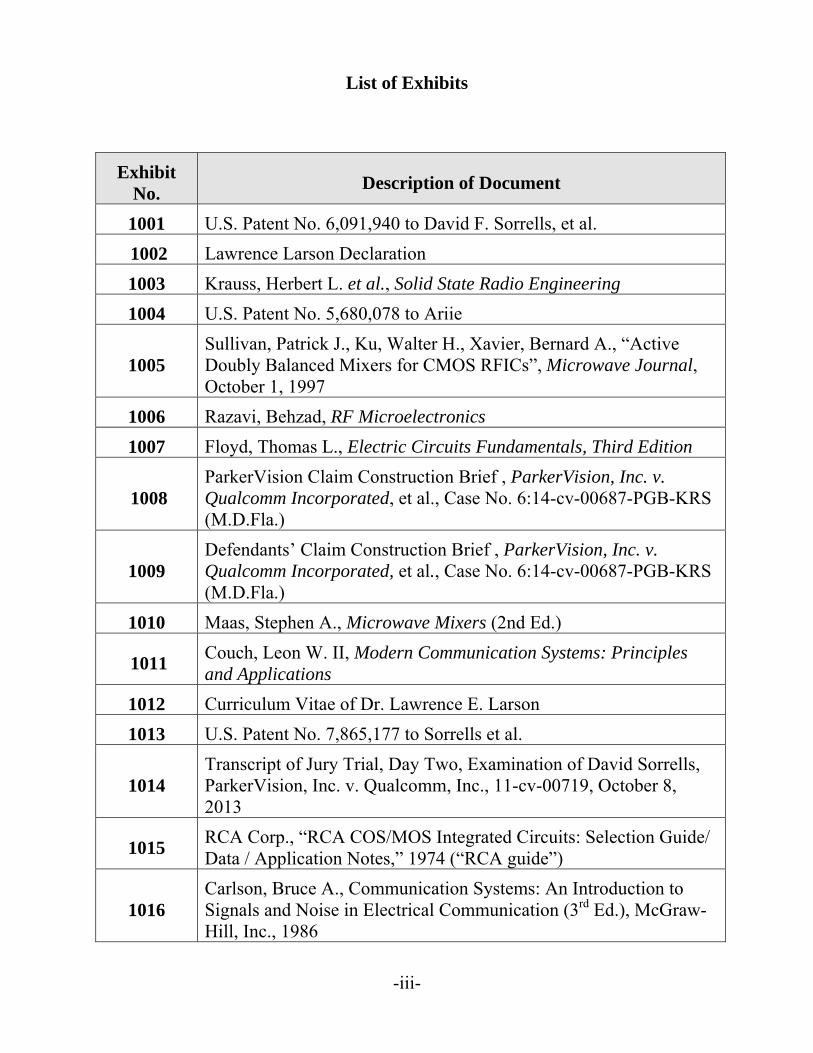
List of Exhibits
-iii-
Exhibit No.
Description of Document
1001 U.S. Patent No. 6,091,940 to David F. Sorrells, et al.
1002 Lawrence Larson Declaration
1003 Krauss, Herbert L. et al., Solid State Radio Engineering
1004 U.S. Patent No. 5,680,078 to Ariie
1005 Sullivan, Patrick J., Ku, Walter H., Xavier, Bernard A., “Active Doubly Balanced Mixers for CMOS RFICs”, Microwave Journal, October 1, 1997
1006 Razavi, Behzad, RF Microelectronics
1007 Floyd, Thomas L., Electric Circuits Fundamentals, Third Edition
1008 ParkerVision Claim Construction Brief , ParkerVision, Inc. v. Qualcomm Incorporated, et al., Case No. 6:14-cv-00687-PGB-KRS (M.D.Fla.)
1009 Defendants’ Claim Construction Brief , ParkerVision, Inc. v. Qualcomm Incorporated, et al., Case No. 6:14-cv-00687-PGB-KRS (M.D.Fla.)
1010 Maas, Stephen A., Microwave Mixers (2nd Ed.)
1011 Couch, Leon W. II, Modern Communication Systems: Principles and Applications
1012 Curriculum Vitae of Dr. Lawrence E. Larson
1013 U.S. Patent No. 7,865,177 to Sorrells et al.
1014 Transcript of Jury Trial, Day Two, Examination of David Sorrells, ParkerVision, Inc. v. Qualcomm, Inc., 11-cv-00719, October 8, 2013
1015 RCA Corp., “RCA COS/MOS Integrated Circuits: Selection Guide/ Data / Application Notes,” 1974 (“RCA guide”)
1016 Carlson, Bruce A., Communication Systems: An Introduction to Signals and Noise in Electrical Communication (3rd Ed.), McGraw-Hill, Inc., 1986
List of Exhibits
-iv-
Exhibit No.
Description of Document
1017 U.S. Patent No. 1,699,570
1018 File History to European Application No. 01926955.4, filed November 2002
1019 The ARRL Handbook (72nd Ed.), The American Radio Relay League, Inc.
1020 Keys, Cynthia D., “Low-Distortion Mixers for RF Communications”
1021 Maemura, K. “The 200MHz- and 1.5GHZ-Band GaAs Monolithic Quadrature Modulator ICs”
1022 Larson, Lawrence, RF and Microwave Circuit Design for Wireless Communications.
1023 U.S. Patent No. 5,280,648 to Pierre Dobrovolny
1024 Smith, Bradford L., et al., Microwave Engineering Handbook
1025 Oppenheimer, Samuel L., Fundamentals of Electric Circuits
1026 Vizmuller, Peter, RF Design Guide: Systems, Circuits, and Equations, Vol. 1
1027 Couch, Leon W.II, Digital and Analog Communication Systems
1028 U.S. Patent No. 5,136,264 to Gregg Nardozza
1029 Encyclopedia of Electronics
1030 Illustrated Dictionary of Electronics
1031 Patent Owner’s Response to Motion to Construe “Pulse Shaping Module” “Pule Shaper” in ParkerVision, Inc. v. Qualcomm Incorporated, et al., Case No. 6:14-cv-00687-PGB-KRS (M.D.Fla.)
1032 U.S. Patent No. 5,027,163 to Pierre Dobrovolny
1033 Declaration from University of Washington
1034 Library of Congress – Catalog Information for RF and Microwave Circuit Design for Wireless Communications
1035 File History for U.S. Patent No. 6,091,940
Petition for Inter Partes Review of Patent No. 6,091,940
1
I. INTRODUCTION
Petitioners Qualcomm Incorporated and Qualcomm Atheros, Inc.
(“Petitioners” or “Qualcomm”) respectfully submit this petition for inter partes
review under 35 U.S.C. §§ 311-319 and 37 C.F.R. § 42 of claim 1 and dependent
claims 81-84, 86, 88-91, 93, and 94, and claim 18 and dependent claims 251-54,
256, 258-61, 263, and 264 (“Petitioned Claims”) of U.S. Patent No. 6,091,940 (Ex.
1001.)
The ʼ940 patent claims methods and systems to up-convert a signal. “The
up-conversion is accomplished by controlling a switch with an oscillating signal,
the frequency of the oscillating signal being selected as a sub-harmonic of the
desired output frequency.” (Ex. 1001, Abstract.) Although subharmonic
transmitters use oscillators that run at relatively low frequencies, they take
advantage of higher frequency “harmonic” signals that the mixer creates—thereby
achieving upconversion to very high frequencies without requiring high frequency
oscillators.
Sub-harmonic upconversion is an old concept. The ‘940 patent does not
claim or describe any new oscillator, amplifier, mixer, switch, filter, or other
component. The ‘940 patent concedes that all of the components recited in its
claims could be purchased “off-the-shelf.” (Ex. 1001, at 27:27 (“may be purchased
‘off-the-shelf’”), 28:26, 29:30, 30:38, 31:46 (same).) Because the concept of sub-
Petition for Inter Partes Review of Patent No. 6,091,940
2
harmonic mixers was old and their components were well-known, Patent Owner
claimed that the point of novelty was a new way of using a sub-harmonic mixer as
an up-converting transmitter. But sub-harmonic up-conversion is a concept nearly
as old as radio itself. United States Patent No. 1,699,570, issued to AT&T in 1929,
notes that “the applicant proposes to use the modulation of the voice currents with
a harmonic of the ‘carrier’ wave instead of the modulation of the voice with the
fundamental ‘carrier’ wave.” (Ex. 1017 at 1:56-1:60.)
None of the structures or concepts claimed in the ‘940 patent are novel and
the Petitioned Claims are invalid as obvious. Petitioners are reasonably likely to
prevail on each proposed ground presented in this Petition, and respectfully request
that the Board institute trial.
II. MANDATORY NOTICES UNDER 37 C.F.R. § 42.8(A)(1)
A. Real Party-In-Interest Under 37 C.F.R. § 42.8(b)(1)
Qualcomm is the real party-in-interest.
B. Related Matters Under 37 C.F.R. § 42.8(b)(2)
ParkerVision, Inc. (“Patent Owner”) asserted the ‘940 patent in
ParkerVision, Inc. v. Qualcomm Incorporated, et al., No. 6:14-cv-00687-PGB-
KRS (M.D. Fla.) (the “Related Litigation”). Qualcomm was served on August 28,
2014.
Petitioners are filing additional petitions for inter partes review on the ‘940
Petition for Inter Partes Review of Patent No. 6,091,940
3
patent and on U.S. Patent Nos. 7,039,372 and 7,966,012, which are also assigned
to Patent Owner.
C. Lead and Back-Up Counsel under 37 C.F.R. § 42.8(b)(3)
Lead Counsel: Timothy S. Teter (No. 47,134) / [email protected] Back-up Counsel: Matthew J. Brigham (No. 44,047) / [email protected] Back-up Counsel: Eamonn Gardner (Reg. No. 63,322) / [email protected] Back-up Counsel: Orion Armon (Reg. No. 65,421) / [email protected] [email protected] Cooley LLP ATTN: Patent Group 1299 Pennsylvania Ave., NW, Suite 700 Washington, DC 20004 Tel: 650-843-5275 Fax: 650-849-7400
D. Service Information
The Petition is being served by FEDERAL EXPRESS to the attorneys of
record, Workman Nydegger, 60 East South Temple, Suite 1000, Salt Lake City UT
84111. Petitioners may be served by e-mail at the address provided above.
E. Power of Attorney
Filed concurrently with this petition per 37 C.F.R. § 42.10(b).
III. PAYMENT OF FEES - 37 C.F.R. § 42.103
This Petition requests inter partes review of twenty-four claims of the ‘940
patent: claim 1 and its dependent claims 81-84, 86, 88-91, 93, and 94, and claim 18
and its dependent claims 251-54, 256, 258-61, 263, and 264. This petition is
accompanied by a payment of $27,400, which includes excess claims fees. 37
C.F.R. § 42.15. This Petition meets the fee requirements of 35 U.S.C. § 312(a)(1).
Petition for Inter Partes Review of Patent No. 6,091,940
4
IV. REQUIREMENTS FOR INTER PARTES REVIEW UNDER 37 C.F.R. § 42.104
A. Grounds for Standing Under 37 C.F.R. § 42.104(a)
Petitioners certify that the ‘940 patent is eligible for IPR and further certify
that Petitioners are not barred or estopped from requesting this IPR.
B. Identification of Challenge Under 37 C.F.R. § 42.104(b)
Petitioners request inter partes review of ‘940 patent claim 1 and dependent
claims 81-84, 86, 88-91, 93, and 94, and claim 18 and dependent claims 251-54,
256, 258-61, 263, and 264 and request that each claim be found unpatentable as
obvious under 35 U.S.C. § 103(a) on the following grounds:
Ground ‘940 Claims Basis for Challenge
1. 1 (81, 82, 83, 84, 88, 89, 90, 91, 94); 18 (251, 252, 253, 254, 258, 259, 260, 261, 264)
Obvious over U.S. Patent 5,280,648 to Dobrovolny in view of Stephen A. Maas, Microwave Mixers under 35 U.S.C. § 103(a)
2. 86, 93, 256, 263 Obvious over U.S. Patent 5,280,648 to Dobrovolny in view of Stephen A. Maas, Microwave Mixers, and “Active Doubly Balanced Mixers for CMOS RFICs” by Patrick J. Sullivan, et al. under 35 U.S.C. § 103(a)
This petition is accompanied by the Declaration of Dr. Lawrence E. Larson,
(Ex. 1002, “Larson Decl.”), an expert in the field.
C. Each of the Cited References is Prior Art to the ‘940 Patent
1. U.S. Patent 5,280,648 to Dobrovolny is prior art
U.S. Patent 5,280,648 to Dobrovolny (“Dobrovolny”) is prior art under 35
Petition for Inter Partes Review of Patent No. 6,091,940
5
U.S.C. § 102(b) because it issued on August 16, 1991, more than a year before the
filing date of the ‘940 patent. (Ex. 1023.)
2. Stephen A. Maas, Microwave Mixers, is prior art
Stephen A. Maas’s Microwave Mixers, 2nd Ed. (“Maas”), is prior art under
35 U.S.C. § 102(b) because it was published in 1993, more than a year before the
filing date of the ‘940 patent. (Ex.1010.) Evidence of publication is provided by
the University of Washington Library. (Ex. 1033.)
3. “Active Doubly Balanced Mixers for CMOS RFICs” by Sullivan, et al. is prior art
“Active Doubly Balanced Mixers for CMOS RFICs” by Patrick J. Sullivan,
et al. (“Sullivan”) is prior art under 35 U.S.C. § 102(b) because it was published in
Microwave Journal on October 1, 1997, more than one year before the October 21,
1998, filing date of the ‘940 patent. (Ex. 1005.) Evidence of publication is
provided by the University of Washington Library. (Ex. 1033.)
D. Institution of Inter Partes Review Under 37 C.F.R. § 42.108(c)
Inter partes review of claim 1 and its dependent claims 81-84, 86, 88-91, 93,
and 94, and claim 18 and its dependent claims 251-54, 256, 258-61, 263, and 264
should be instituted because a reasonable likelihood exists that Petitioners will
prevail with respect to each of the claims challenged. 35 U.S.C. § 314(a).
V. SUMMARY OF THE ‘940 PATENT
The ‘940 patent generally claims an up-converting sub-harmonic mixer
Petition for Inter Partes Review of Patent No. 6,091,940
6
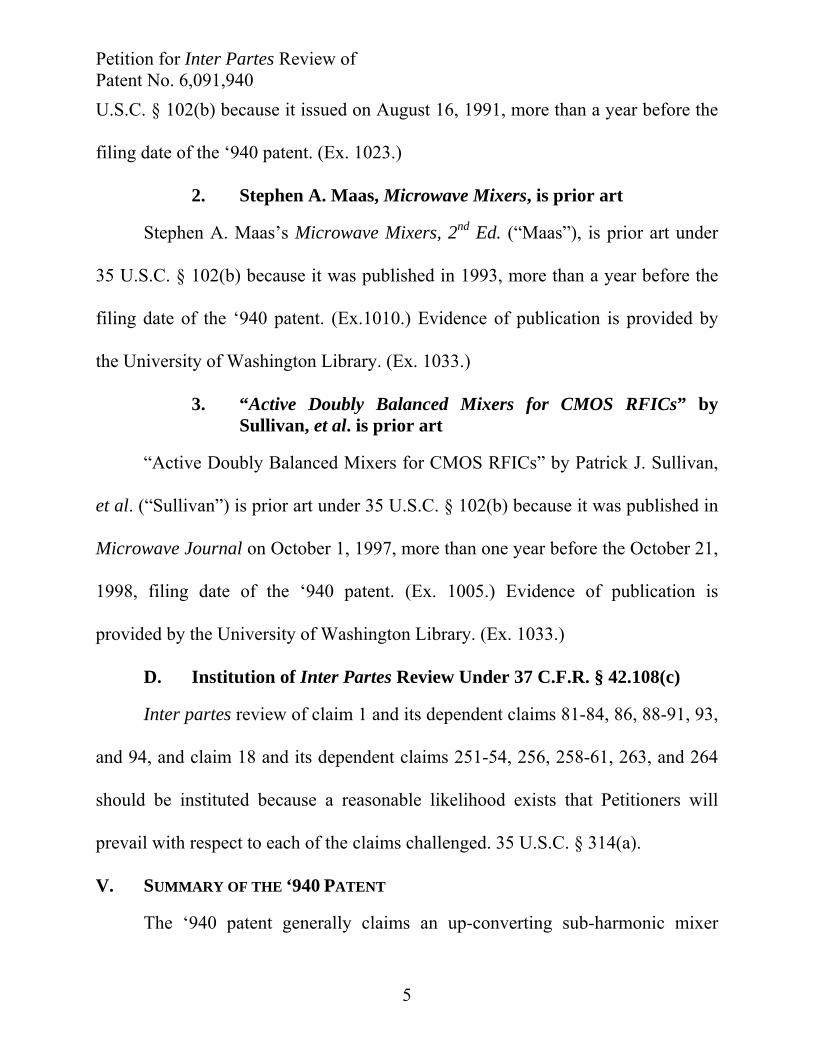
comprising two switch modules, a summing device that sums the outputs of the
switch modules, and a filter for filtering out a desired harmonic signal. (Ex. 1001,
66:51-67:5.) Each of these structural components is highlighted in ‘940 Figure 18:
‘940 Patent Figure 18 (annotated) (Ex. 1001)
Other claims of the ‘940 patent recite additional elements such as a “pulse shaper”
that allegedly maximizes the number and amplitude of desired harmonics output by
the switch modules (Ex. 1001 at 69:19-32), or an “aliasing module” module that
downconverts a signal (Ex. 1001 at 69:54-67). The grounds presented below
demonstrate that the Petitioned Claims are invalid as obvious.
A. The Petitioned Claims of the ‘940 Patent
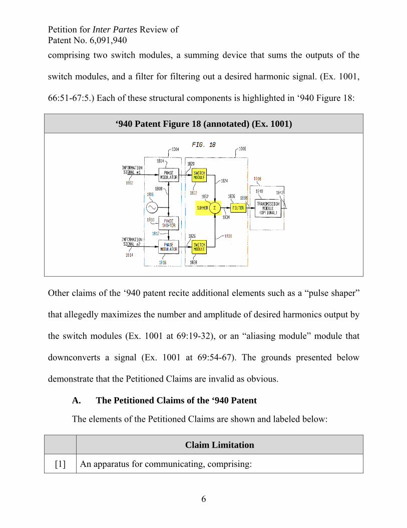
The elements of the Petitioned Claims are shown and labeled below:
Claim Limitation
[1] An apparatus for communicating, comprising:

Petition for Inter Partes Review of Patent No. 6,091,940
7
[1a] a first switch module that receives a first oscillating signal and a first bias signal, wherein said first oscillating signal causes said first switch module to gate said first bias signal and thereby generate a first periodic signal having a first plurality of harmonics, said first periodic signal having an amplitude that is a function of said first bias signal;
[1b] a second switch module that receives a second oscillating signal and a second bias signal, wherein said second oscillating signal causes said second switch module to gate said second bias signal and thereby generate a second periodic signal having a second plurality of harmonics, said second periodic signal having an amplitude that is a function of said second bias signal;
[1c] a summer coupled to said first switch module and to said second switch module, said summer to receive and combine said first periodic signal and said second periodic signal, and to output a combined periodic signal having a combined plurality of harmonics; and
[1d] a filter coupled to said summer, said filter to isolate at least one of said combined plurality of harmonics.
[18] An apparatus for communicating, comprising:
[18a] a first switch module to receive a first oscillating signal and a first bias signal, wherein said first oscillating signal causes said first switch module to gate said first bias signal and thereby generate a first periodic signal having a first plurality of harmonics, said first periodic signal having an amplitude that is a function of said first bias signal, said first bias signal being a function of a first information signal;
[18b] a second switch module to receive a second oscillating signal and a second bias signal, wherein said second oscillating signal causes said second switch module to gate said second bias signal and thereby generate a second periodic signal having a second plurality of harmonics, said second periodic signal having an amplitude that is a function of said second bias signal, said second bias signal being a function of a second information signal;
[18c] a summer coupled to said first switch module and to said second switch module, said summer to receive and combine said first periodic signal and said second periodic signal, and to output a combined periodic signal
Petition for Inter Partes Review of Patent No. 6,091,940
8
having a combined plurality of harmonics; and
[18d] a filter coupled to said summer, said filter to isolate at least one of said combined plurality of harmonics.
[81] The apparatus of claim 1, wherein said first switch module is a electronic device.
[82] The apparatus of claim 81, wherein said electronic device is a semiconductor device.
[83] The apparatus of claim 82, wherein said semiconductor device is a transistor.
[84] The apparatus of claim 83, wherein said transistor is a field effect transistor.
[86] The apparatus of claim 84, wherein said field effect transistor is a complementary metal oxide semiconductor field effect transistor.
[88] The apparatus of claim 1, wherein said second switch module is a electronic device.
[89] The apparatus of claim 88, wherein said electronic device is a semiconductor device.
[90] The apparatus of claim 89, wherein said semiconductor device is a transistor.
[91] The apparatus of claim 90, wherein said transistor is a field effect transistor.
[93] The apparatus of claim 91, wherein said field effect transistor is a complementary metal oxide semiconductor field effect transistor.
[94] The apparatus of claim 1, wherein said first plurality of harmonics are harmonics of the fundamental frequency of said first periodic signal and said second plurality of harmonics are harmonics of the fundamental frequency of said second periodic signal.
[251] The apparatus of claim 18, wherein said first switch module is an electronic device.

Petition for Inter Partes Review of Patent No. 6,091,940
9
[252] The apparatus of claim 251, wherein said electronic device is a semiconductor device.
[253] The apparatus of claim 252, wherein said semiconductor device is a transistor.
[254] The apparatus of claim 253, wherein said transistor is a field effect transistor.
[256] The apparatus of claim 254, wherein said field effect transistor is a complementary metal oxide semiconductor field effect transistor.
[258] The apparatus of claim 18, wherein said second switch module is an electronic device.
[259] The apparatus of claim 258, wherein said electronic device is a semiconductor device.
[260] The apparatus of claim 259, wherein said semiconductor device is a transistor.
[261] The apparatus of claim 260, wherein said transistor is a field effect transistor.
[263] The apparatus of claim 261, wherein said field effect transistor is a complementary metal oxide semiconductor field effect transistor.
[264] The apparatus of claim 18, wherein said first plurality of harmonics are harmonics of the fundamental frequency of said first periodic signal and said second plurality of harmonics are harmonics of the fundamental frequency of said second periodic signal.
B. Priority Date of the Petitioned Claims
The priority date of the Petitioned Claims is October 21, 1998, the ‘940
patent filing date.
VI. BACKGROUND OF TECHNOLOGY RELATED TO THE ‘940 PATENT
Dr. Larson provides a technology tutorial in his declaration. (Ex. 1002 at ¶¶
Petition for Inter Partes Review of Patent No. 6,091,940
10
40-101.)
A. The Art of RF Circuit Design Was Advanced by 1998
By 1996, the wireless communication industry was technically advanced.
(Ex. 1002, Larson Decl., at ¶ 102; Ex. 1022, Larson at 7-8.) Wireless
communications technologies had been in wide use in the consumer marketplace
for over fifteen years and rapid technological advancements in RF circuit design
had been achieved. (Ex. 1002 at ¶ 103; Ex. 1022 at 7 (“this field has developed so
rapidly that traditional communications and analog circuit design textbooks have
struggled to keep up with all of the advances in the field.”).) The technologically
advanced state of the radio transceiver industry influenced how RF circuit
designers worked. (Ex. 1002 at ¶ 105.) Circuit designers would survey the state-of-
the-art in radio transceiver component technology before commencing the design
process because mature component data was widely available. (Ex. 1022 at 14.)
Persons of ordinary skill in the art possessed a sophisticated understanding of the
possibilities for combining component technologies to satisfy the design
requirements for a given RF circuit application, and a high level of confidence that
the end result would work for its intended purpose. (Ex. 1002 at ¶ 106.)
As with the other components used in RF transceiver systems, the state of
the art of mixer technology was also advanced by 1996. Stephen Maas, a well-
known expert in RF mixers observed at the time, “[i]n the past twenty years, mixer
Petition for Inter Partes Review of Patent No. 6,091,940
11
technology has evolved from a major research topic into one of great maturity.”
(Ex.1022 at 35.) The state of the art of RF circuit design in 1996 (i.e., two years
before the priority date of the ‘940 patent) was such that persons of ordinary skill
in the art routinely designed RF transceiver systems and RF circuit subcomponents
without inventive effort. (Ex. 1002 at ¶¶ 108-109.)
VII. CLAIM CONSTRUCTION UNDER 37 C.F.R. § 42.104(b)(3)
A claim subject to IPR is given its “broadest reasonable construction in light
of the specification of the patent in which it appears.” 37 C.F.R. § 42.100(b).
1. Person of ordinary skill in the art
A person of ordinary skill in the art as of October 1998 would possess, at a
minimum, either (a) a master of science degree in electrical engineering and two or
more years of experience in radio frequency circuit design, or (b) a bachelor of
science degree in electrical engineering with three or more years of experience
with the design and development of RF circuits. (Ex. 1002 at ¶¶ 24-29.)
2. “switch”/“switch module”
The term “switch” is well known in the art as a device that has two states:
the “closed” or “on” state (zero voltage across it, or the voltage is the same on each
side) and the “open” or “off” state (zero current through it). (Ex. 1003, Krauss at
77 (“[A] switch S that is either on (with zero voltage across it) or off (with zero
current through it) except for very brief periods of time during the transitions

Petition for Inter Partes Review of Patent No. 6,091,940
12
between on and off states.”) (emphasis in original); id. at 21-23 and 76 (“an ideal
switch has either zero voltage across it or zero current through it at all times”); Ex.
1006, Razavi at 6 (“[I]n the simple circuit of Fig. 6.15(a), . . . the output is equal to
the RF input when S1 is on and zero when S1 is off.”)) The ‘940 patent uses the
terms “switch” and “switch module” consistent with that well-known definition.
For example, the ʼ940 patent describes the operation of a switch as taking one of
these two states:
This shaped signal is then used to control a switch which opens and
closes as a function of the frequency and pulse width of the shaped
signal.
(Ex. 1001 at 1:65-67.)
When the switch 2816 is “open,” the output 2822 of switch module
2802 is at substantially the same voltage level as bias signal 2806.
Thus, since the harmonically rich signal 2814 is connected directly to
the output 2822 of switch module 2802, the amplitude of
harmonically rich signal 2814 is equal to the amplitude of the bias
signal 2806. When the modulated oscillating signal 2804 causes the
switch 2816 to become “closed,” the output 2822 of switch module
2802 becomes connected electrically to the second input 2810 of
switch module 2802 (e.g., ground 2812 in one embodiment of the
invention), and the amplitude of the harmonically rich signal 2814
becomes equal to the potential present at the second input 2810.
(Ex. 1001 at 33:59-34:5.)
Petition for Inter Partes Review of Patent No. 6,091,940
13
The broadest reasonable interpretation of “switch”/“switch module” is thus
“a device with an input and an output that can take two states, open and closed, and
when closed electrically connects its input and output such that the input and
output have an equal voltage.” (Ex. 1009, Defendants’ Claim Construction Brief at
13.)
In the Related Litigation, the Patent Owner proposed that “switch”/“switch
module” should be construed as “to generate a periodic signal having a plurality of
harmonics from an input signal and a control signal.” (Ex. 1008 at 16.) The Patent
Owner’s construction is not the broadest reasonable interpretation because it
describes a desired result rather than the claimed structure of a “switch” or “switch
module.” A device configured to operate as a “switch”/“switch module” is a
“switch”/“switch module” regardless whether it is producing the Patent Owner’s
desired results. Accordingly, the Patent Owner’s construction in erroneous. (Ex.
1002 at ¶¶ 114-117.)
3. “to gate [a signal]”/“gating [a signal]”
The term “to gate” or “gating” is used throughout the ʼ940 patent. The
specification of the ‘940 patent uses “gating” to describe the operation of a
“switch” or “switch module”: “[a]s the switch opens and closes, it gates a reference
signal which is the information signal.” (Ex. 1001 at 2:8-10.) Consistent with the
specification’s description that a switch “gates” a signal, a person of skill in the art

Petition for Inter Partes Review of Patent No. 6,091,940
14
would understand “gating” as referring to the opening and closing (changing of
state) of the switch. (See also Section VII(2) above, discussion of “switch”/“switch
module”.) Therefore, the broadest reasonable interpretation of this term is “to
change/changing between (i) connecting a signal at an input to an output such that
the input and output have an equal voltage, and (ii) disconnecting the signal from
the output.” (See also, Ex. 1001 at 34:64-67, 36:33-57, and 41:44-42:19.)
In the Related Litigation, Patent Owner has proposed that this term means
“to generate a periodic signal having a plurality of harmonics from an input signal
and a control signal.” (Ex. 1008 at 16.) Patent Owner’s proposed construction is
improper because it describes a potential result of gating a signal using a switch in
a mixer, rather than what constitutes “gating”. (Ex. 1002 at ¶¶ 118-121.)
4. “harmonic”
The ʼ940 patent describes a device that is designed to create a large number
of “harmonic” frequencies (each an integer multiple of the lower, fundamental
frequency), allowing a stable, low frequency signal to be used to create higher
frequency signals. (Ex. 1001 at 1:45-52.) The ‘940 patent defines “harmonic” as a
frequency that is “compared to its fundamental or reference frequency” (and thus is
different from it) and “an integer multiple of” that fundamental frequency, where
the integer “‘n’ is 2, 3, 4, etc.”:
Petition for Inter Partes Review of Patent No. 6,091,940
15
Harmonic: A harmonic is a frequency or tone that, when compared to
its fundamental or reference frequency or tone, is an integer multiple
of it. In other words, if a periodic waveform has a fundamental
frequency of ‘f’ (also called the first harmonic), then its harmonics
may be located at frequencies of ‘n•f,’ where “n” is 2, 3, 4, etc. The
harmonic corresponding to n=2 is referred to as the second harmonic,
the harmonic corresponding to n=3 is referred to as the third
harmonic, and so on.
(Ex. 1001 at 8:22-30.)
As used in the Petitioned Claims and in the definition quoted above,
“harmonic” does not include the fundamental frequency (i.e., “harmonic” excludes
n=1). This definition is consistent with every embodiment in the ʼ940 patent,
which describes and claims a transmitter that uses a low frequency oscillating
signal to create higher frequency harmonics that can be transmitted. Thus, the
broadest reasonable interpretation of “harmonic” is “a frequency or tone that is an
integer multiple of the frequency of the oscillating signal, i.e., if the oscillating
signal has a fundamental frequency of ‘f’ then its harmonics may be located at
frequencies of ‘n•f,’ where ‘n’ is 2, 3, 4, etc.” Defining “harmonic” to be a multiple
(n>1) is consistent with technical dictionaries at the time. (Ex. 1030, Illustrated
Dictionary of Electronics, at 6 (defining “harmonic” to be “…a multiple of the
FUNDAMENTAL FREQUENCY by a whole-number factor of 2 or more”).)
In the Related Litigation, the Patent Owner argued that the fundamental
Petition for Inter Partes Review of Patent No. 6,091,940
16
frequency (n=1) should be included within the definition of “harmonic” because
the specification of the ‘940 patent refers to the fundamental frequency as the “first
harmonic.” (Ex. 1008 at 9-12.) But the Patent Owner ignored the context of those
statements, the context of the claims, and the ‘940 specification. For example, in
ʼ940 Figure 14, the only purpose of the switch module is to generate higher
frequency signals that can be transmitted (i.e., to upconvert); the switch module
would be superfluous if “harmonic” included the fundamental frequency (n>1). In
other words, if the claimed “harmonic” included the fundamental frequency (n=1),
then the “switch module” would have no purpose and, in fact, would be
detrimental to the operation of the system. (Ex. 1002 at ¶¶ 122-125.)
5. “summer”
The claimed “summer” adds two voltages, as shown in every embodiment in
the ‘940 patent. Thus, the broadest reasonable interpretation of “summer” is “a
device that sums two or more signals.” This construction is consistent with the
description of the summer in the ʼ940 patent. (See Ex. 1001 at 37:22-27 (“The
invention supports numerous embodiments of the summer. Exemplary
embodiments of the summer 3402 (FIG. 34) are described below. However, it
should be understood that these examples are provided for illustrative purposes
only. The invention is not limited to these embodiments.”).)
In the Related Litigation, the Patent Owner proposed that the claimed

Petition for Inter Partes Review of Patent No. 6,091,940
17
“summer” does not need to be a device, but instead, can be nothing more than a
connection between two wires. (Ex. 1008 at 32-34.) To support its infringement
theory, the Patent Owner proposed that the term “summer” be construed to mean
“a circuit that produces a signal which is the arithmetic sum of two or more
signals.” (Ex. 1008 at 32.) The Patent Owner’s construction is erroneous; a
connection between two wires cannot add voltages together because it would
violate Kirchhoff’s Voltage Law, which requires that all points along a wire
(assuming substantially zero resistance), and all inputs to a node, have the same
voltage. (Ex. 1007, Floyd, at 8 (“the algebraic sum of all the voltages around a
closed path is zero”).) Petitioners’ construction is consistent with the broadest
reasonable interpretation of the claim language and specification—the claimed
“summer”/“summing means” is “a device that sums two or more signals.” (Ex.
1002 at ¶¶ 126-127.)
VIII. OVERVIEW OF THE INVALIDATING REFERENCES
The Petitioned Claims of the ‘940 patent are invalid for obviousness in light
of the teachings of the prior art references described below. In particular, U.S.
Patent 5,280,648 to Dobrovolny describes the structure of the Petitioned Claims.
Maas, Microwave Mixers, teaches persons of ordinary skill in the art how to use
that structure to generate and isolate higher frequency harmonics, and Sullivan
teaches persons of ordinary skill in the art to make such devices using well-known
Petition for Inter Partes Review of Patent No. 6,091,940
18
CMOS technology and FETs. None of the prior art references supporting the
invalidity grounds in this petition were before the patent examiner during the
patent examination process.
A. Overview of Dobrovolny
U.S. Patent 5,280,648 to Dobrovolny discloses a device for upconverting.
(Ex. 1023 at 1:18-22, Figs. 1-4.) Figures 1 and 2 of Dobrovolny disclose a system
that upconverts a high level RF signal 10. (Ex. 1023 at 2:49-55, Figs. 1-2.) Figure
1, below, shows key components of the upconverter, including high level RF signal
10 coupled to bifilar balun 11 which inverts the signal (creating one non-inverted
signal and one inverted signal phase shifted 180°). (Ex. 1023 at 2:49-3:47, Figs. 1-
3.) A square wave symmetric local oscillating signal is generated from LO Source
40. (Id.) The LO Source includes a balun that inverts one local oscillator signal
relative to the other by 180°. (Id.) The upconverter includes two GaAs MESFET
switches 22 and 26 that operate under control of the local oscillating signals. (Id.)
In combination with the operation of the switches, trifilar transformer 14 sums the
voltages of the signals generated by the switches, producing a waveform C at the
IF Out port that includes multiple harmonics. (Id.) Annotated Figure 1 shows the
key aspects of Dobrovolny’s upconverter:

Petition for Inter Partes Review of Patent No. 6,091,940
19
Dobrovolny Fig. 1 (annotated) (Ex. 1023)
B. Overview of Maas
Dobrovolny describes the structure of the ‘940 patent—Maas encourages
persons of ordinary skill to use that structure as claimed in the ‘940 patent. In
particular, Maas encourages persons of ordinary skill in the art to use mixers (such
as the Dobrovolny design) to generate higher frequency harmonics, which can then
be selected for transmission. Microwave Mixers, Second Edition, by Stephen A.
Maas was published in 1993 by Artech House, Inc. (Ex. 1010.) Maas’s book
teaches the fundamentals of mixer design, mixer theory, and how to
subharmonically drive a mixer to generate harmonics that can be filtered at the

Petition for Inter Partes Review of Patent No. 6,091,940
20
output to achieve up-conversion. (Ex. 1010, Maas at 9-10 and 25-26.)
As Maas explains, a “sub-harmonically pumped mixer” is driven at a
frequency lower than that of the desired local oscillator (LO) signal—the strategy
that the ‘940 patent embraces. (Ex. 1010 at 25.) For example, Maas discusses
pumping (driving) the mixer at half the LO frequency and mixing the RF signal
with the second harmonic of the junction’s conductance waveform. (Ex. 1010 at
25.) The motivation for such a sub-harmonic architecture is that “it is expensive,
inconvenient, or even impossible to generate a fundamental-frequency LO” in
many applications. (Ex. 1010 at 25.) Thus, persons of ordinary skill in the art
would have been motivated to use the Dobrovolny structure to generate high
frequency harmonics, for reduced expense and enhanced convenience.
C. Overview of Sullivan
The article “Active Doubly Balanced Mixers for CMOS RFICs” was
published by Patrick J. Sullivan, et al. in Microwave Journal on October 1, 1997
(hereafter “Sullivan”). Sullivan is directed to mixers for CMOS RF integrated
circuits. (Ex. 1005, Sullivan, at Title, 1, 3.) Sullivan teaches that CMOS FETs are
alternatives to MESFET switches in mixers like Dobrovolny’s: “The drive to
increase transceiver integration and reduce transceiver cost makes CMOS an
attractive technology for low cost, highly integrated transceivers.” (Ex. 1005 at 9.)
Petition for Inter Partes Review of Patent No. 6,091,940
21
D. Dobrovolny, Maas, and Sullivan Are Analogous Art
The prior art references supporting the proposed grounds are analogous art
to the ‘940 patent because each prior art reference concerns RF upconverters and
RF circuit design. Accordingly, it would have been obvious to an RF circuit
designer in 1998 to consult and combine the teachings of the cited prior art
references.
IX. APPLICATION OF THE PRIOR ART TO THE CLAIMS OF THE ‘940 PATENT
A. Ground 1 – Dobrovolny and Maas Render Claim 1 and Dependent Claims 81, 82, 83, 84, 88, 89, 90, 91, and 94, and Claim 18 and Dependent claims 251, 252, 253, 254, 258, 259, 260, 261, and 264 Obvious Under 35 U.S.C. § 103(a)
Dobrovolny in light of Maas renders independent claim 1 and dependent
claims 81, 82, 83, 84, 88, 89, 90, 91, and 94, and independent claim 18 and
dependent claims 251, 252, 253, 254, 258, 259, 260, 261, and 264 obvious under
35 U.S.C. § 103(a) for the reasons set forth below:
1. Claim 1
a. Dobrovolny discloses the preamble [1]
[1] An apparatus for communicating, comprising:
Dobrovolny discloses an apparatus for communicating: “This invention
relates in general to CATV mixers and in particular to commutating type single
and double-balanced resistive RF mixers that are operable with high level RF input
signals.” (Ex. 1023 at 1:14-17.) “CATV” refers to “community antenna television”

Petition for Inter Partes Review of Patent No. 6,091,940
22
or “Cable TV.” (Ex. 1002 at ¶ 133.) “RF” refers to “radio frequency.” (Ex. 1023 at
1:22.) Accordingly, Dobrovolny discloses an apparatus for communicating radio
frequency television signals.
b. Dobrovolny and Maas render obvious elements [1a] and [1b]
[1a] a first switch module that receives a first oscillating signal and a first bias signal, wherein said first oscillating signal causes said first switch module to gate said first bias signal and thereby generate a first periodic signal having a first plurality of harmonics, said first periodic signal having an amplitude that is a function of said first bias signal;
[1b] a second switch module that receives a second oscillating signal and a second bias signal, wherein said second oscillating signal causes said second switch module to gate said second bias signal and thereby generate a second periodic signal having a second plurality of harmonics, said second periodic signal having an amplitude that is a function of said second bias signal;
Dobrovolny in light of Maas discloses claim elements [1a] and [1b].
Dobrovolny describes two different types of upconverter (single and double-
balanced mixers). This Petition will focus on Dobrovolny’s description of a single-
balanced mixer comprised of two switches that satisfies all of the structural
limitations of elements [1a] and [1b]. Maas teaches how to subharmonically pump
Dobrovolny’s upconverter to generate desired harmonics. Each sub-element of [1a]
and [1b] is addressed below.
(1) Claim element 1(a)(i) “first switch module” and 1(b)(i) “second switch module”
Dobrovolny discloses a “first switch module” and a “second switch
Petition for Inter Partes Review of Patent No. 6,091,940
23
module”. The broadest reasonable interpretation of “switch module” is “a device
with an input and an output that can take two states, open and closed, and when
closed electrically connects its input and output such that the input and output have
an equal voltage.” (Ex. 1002 at ¶ 135, 191.)
Figure 1 of Dobrovolny shows an upconverter that includes two Gallium
arsenide (“GaAs”) metal–semiconductor field effect transistor (“MESFET”)
switches 22 and 26: “Windings 16 and 17 have their other terminals connected to
respective drain electrodes of a pair of GaAs MESFET devices 22 and 26,
respectively. These devices may comprise, for example, NEC MESFETS
NE72084.” (Ex. 1023 at 2:60-64.) As Dobrovolny’s characterization underscores,
MESFET switches are devices.
Referring to an equivalent embodiment in the “single-balanced resistive
mixer of the cross-referenced application Ser. No. 281,156, U.S. Pat. No.
5,027,163,” Dobrovolny confirms that the MESFETS act as switches, noting that
the “pair of GaAs MESFETS” are “for high speed switching.” (Ex. 1023 at 1:66-
67; 2:2-3 (emphasis added); Ex. 1032, Pat. 5,027,163 at Fig. 1.) GaAs MESFET 22
satisfies the “first switch module” limitation and MESFET 26 satisfies the “second
switch module” limitation.
Switches 22 and 26 are capable of taking two states (open and closed),
determined by the local oscillating control signal. (Ex. 1003 at 77 (“[A] switch S
Petition for Inter Partes Review of Patent No. 6,091,940
24
that is either on (with zero voltage across it) or off (with zero current through it)
except for very brief periods of time during the transitions between on and off
states.”); id. at 21-23 and 76 (“an ideal switch has either zero voltage across it or
zero current through it at all times”).)
As is understood by those of skill in the art, when switches 22 and 26 are
closed (or on) they electrically connect the input and output so that both are at an
equal voltage. (Ex. 1006 at 6 (“[I]n the simple circuit of Fig. 6.15(a), . . . the output
is equal to the RF input when S1 is on and zero when S1 is off.”); Ex.1003 at 76
and 77; Ex. 1002 at ¶¶ 140, 197.)
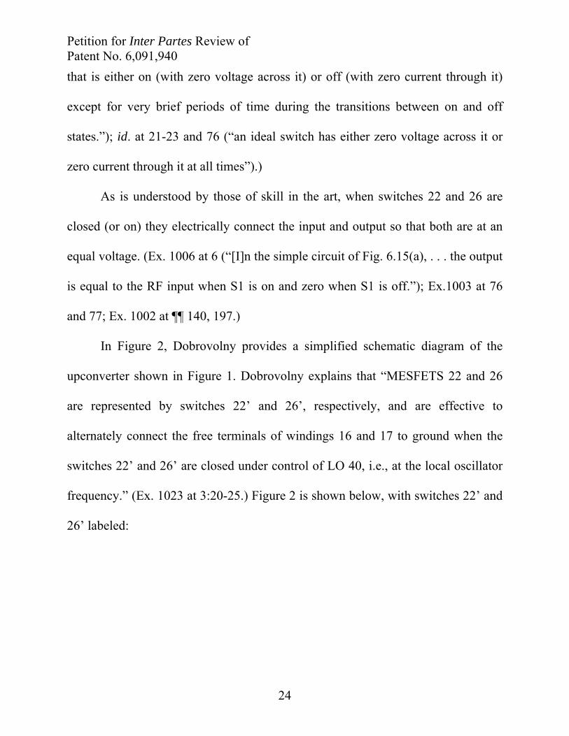
In Figure 2, Dobrovolny provides a simplified schematic diagram of the
upconverter shown in Figure 1. Dobrovolny explains that “MESFETS 22 and 26
are represented by switches 22’ and 26’, respectively, and are effective to
alternately connect the free terminals of windings 16 and 17 to ground when the
switches 22’ and 26’ are closed under control of LO 40, i.e., at the local oscillator
frequency.” (Ex. 1023 at 3:20-25.) Figure 2 is shown below, with switches 22’ and
26’ labeled:
Petition for Inter Partes Review of Patent No. 6,091,940
25
Dobrovolny Figure 2, Annotated (Ex. 1023)
Switches 22 and 26 electrically connect their inputs and outputs when they
close. “MESFETS 22 and 26 are represented by switches 22’ and 26’, respectively,
and are effective to alternately connect the free terminals of windings 16 and 17 to
ground when the switches 22’ and 26’ are closed under control of LO 40, i.e., at
the local oscillator frequency.” (Ex.1023 at 3:20-25.) The input (RF In) and output
(IF Out) of each respective switch 22 and 26 becomes connected when “the free
terminals of windings 16 and 17” are alternately connected to common ground
across each switch. When switch 22 closes, the voltage in winding 16 develops at
the IF output terminal 25; during this time switch 26 is open and no output voltage
is induced due to output winding 17. (Ex. 1023 at 3:17-30; Ex. 1002 at ¶ 144, 200.)
When switch 26 closes, the voltage in winding 17 develops at IF Output terminal
25; during this time switch 22 is open and no output voltage is induced due to
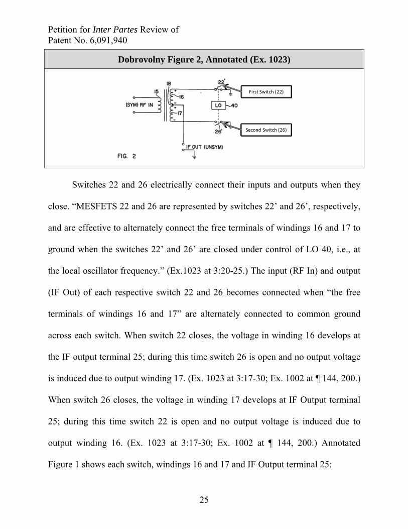
output winding 16. (Ex. 1023 at 3:17-30; Ex. 1002 at ¶ 144, 200.) Annotated
Figure 1 shows each switch, windings 16 and 17 and IF Output terminal 25:
Petition for Inter Partes Review of Patent No. 6,091,940
26
Dobrovolny Figure 1, Annotated (Ex. 1023)
(2) Claim element 1(a)(ii) “first oscillating signal” and
1(b)(ii) “second oscillating signal”
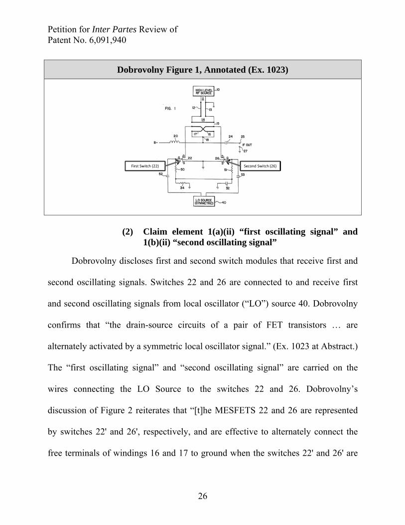
Dobrovolny discloses first and second switch modules that receive first and
second oscillating signals. Switches 22 and 26 are connected to and receive first
and second oscillating signals from local oscillator (“LO”) source 40. Dobrovolny
confirms that “the drain-source circuits of a pair of FET transistors … are
alternately activated by a symmetric local oscillator signal.” (Ex. 1023 at Abstract.)
The “first oscillating signal” and “second oscillating signal” are carried on the
wires connecting the LO Source to the switches 22 and 26. Dobrovolny’s
discussion of Figure 2 reiterates that “[t]he MESFETS 22 and 26 are represented
by switches 22' and 26', respectively, and are effective to alternately connect the
free terminals of windings 16 and 17 to ground when the switches 22' and 26' are
Petition for Inter Partes Review of Patent No. 6,091,940
27
closed under control of LO 40, i.e., at the local oscillator frequency.” (Ex. 1023
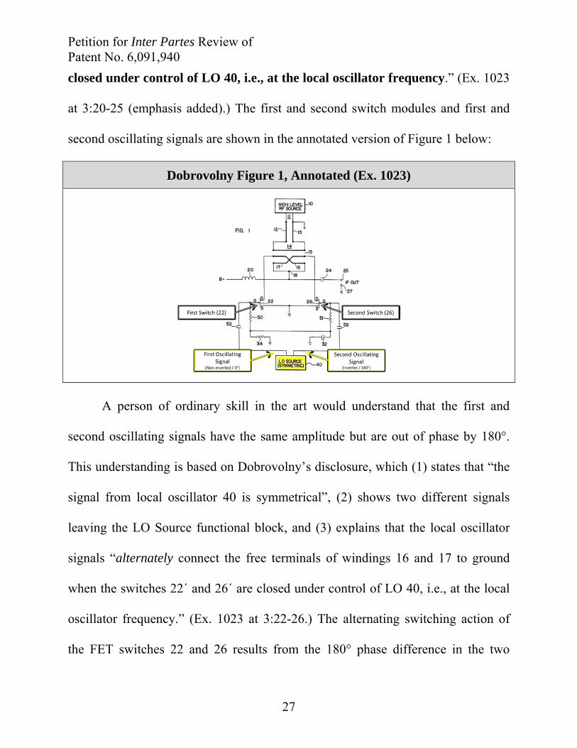
at 3:20-25 (emphasis added).) The first and second switch modules and first and
second oscillating signals are shown in the annotated version of Figure 1 below:
Dobrovolny Figure 1, Annotated (Ex. 1023)
A person of ordinary skill in the art would understand that the first and
second oscillating signals have the same amplitude but are out of phase by 180°.
This understanding is based on Dobrovolny’s disclosure, which (1) states that “the
signal from local oscillator 40 is symmetrical”, (2) shows two different signals
leaving the LO Source functional block, and (3) explains that the local oscillator
signals “alternately connect the free terminals of windings 16 and 17 to ground
when the switches 22´ and 26´ are closed under control of LO 40, i.e., at the local
oscillator frequency.” (Ex. 1023 at 3:22-26.) The alternating switching action of
the FET switches 22 and 26 results from the 180° phase difference in the two

Petition for Inter Partes Review of Patent No. 6,091,940
28
oscillating signals, which causes one switch to open when the other is closed. (Ex.
1002 at ¶¶ 148, 204.)
Persons of ordinary skill in the art recognize that symmetric signals
produced by the application of a signal to a phase splitting network satisfy the
“first” and “second” local oscillating signal elements because the phase of the
signals is different (i.e., one is non-inverted at 0° and the other is inverted 180° out
of phase relative to the first signal). (See, e.g., Ex. 1003, Krauss at 80 (“The audio
input signal is applied to a phase-splitting network that produces two audio
signals that differ in phase by 90°. These signals are then applied to two double-
balanced mixers…”)(emphasis added); Ex. 1002 at ¶ 152.)
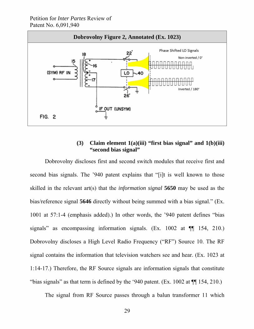
Annotated Dobrovolny Figure 2 below illustrates the phase shifted local
oscillating signals generated by LO Source 40. The LO Signal waveform is copied
from Figure 3(b), which shows “a local oscillator-controlled polarity multiplier
(i.e., representing the action of LO-controlled switches 22´ and 26´).” (Ex. 1023 at
3:33-35.)
Petition for Inter Partes Review of Patent No. 6,091,940
29
Dobrovolny Figure 2, Annotated (Ex. 1023)
(3) Claim element 1(a)(iii) “first bias signal” and 1(b)(iii) “second bias signal”
Dobrovolny discloses first and second switch modules that receive first and
second bias signals. The ʼ940 patent explains that “[i]t is well known to those
skilled in the relevant art(s) that the information signal 5650 may be used as the
bias/reference signal 5646 directly without being summed with a bias signal.” (Ex.
1001 at 57:1-4 (emphasis added).) In other words, the ʼ940 patent defines “bias
signals” as encompassing information signals. (Ex. 1002 at ¶¶ 154, 210.)
Dobrovolny discloses a High Level Radio Frequency (“RF”) Source 10. The RF
signal contains the information that television watchers see and hear. (Ex. 1023 at
1:14-17.) Therefore, the RF Source signals are information signals that constitute
“bias signals” as that term is defined by the ‘940 patent. (Ex. 1002 at ¶¶ 154, 210.)
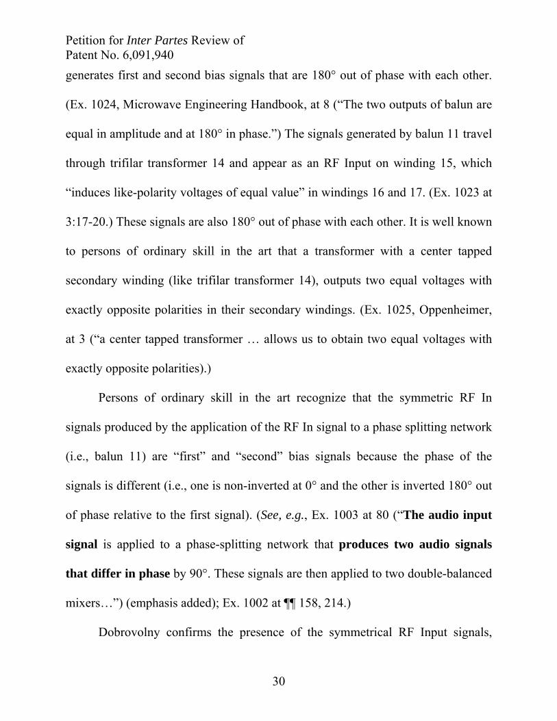
The signal from RF Source passes through a balun transformer 11 which
Petition for Inter Partes Review of Patent No. 6,091,940
30
generates first and second bias signals that are 180° out of phase with each other.
(Ex. 1024, Microwave Engineering Handbook, at 8 (“The two outputs of balun are
equal in amplitude and at 180° in phase.”) The signals generated by balun 11 travel
through trifilar transformer 14 and appear as an RF Input on winding 15, which
“induces like-polarity voltages of equal value” in windings 16 and 17. (Ex. 1023 at
3:17-20.) These signals are also 180° out of phase with each other. It is well known
to persons of ordinary skill in the art that a transformer with a center tapped
secondary winding (like trifilar transformer 14), outputs two equal voltages with
exactly opposite polarities in their secondary windings. (Ex. 1025, Oppenheimer,
at 3 (“a center tapped transformer … allows us to obtain two equal voltages with
exactly opposite polarities).)
Persons of ordinary skill in the art recognize that the symmetric RF In
signals produced by the application of the RF In signal to a phase splitting network
(i.e., balun 11) are “first” and “second” bias signals because the phase of the
signals is different (i.e., one is non-inverted at 0° and the other is inverted 180° out
of phase relative to the first signal). (See, e.g., Ex. 1003 at 80 (“The audio input
signal is applied to a phase-splitting network that produces two audio signals
that differ in phase by 90°. These signals are then applied to two double-balanced
mixers…”) (emphasis added); Ex. 1002 at ¶¶ 158, 214.)
Dobrovolny confirms the presence of the symmetrical RF Input signals,
Petition for Inter Partes Review of Patent No. 6,091,940
31
which constitute the first and second bias signals. (Ex. 1023 at 3:25-27 (“As
mentioned, the signal from local oscillator 40 is symmetrical, as is the RF input
signal across winding 15.” (emphasis added).) The first and second bias signals,
out of phase with each other by 180° are shown in annotated Figure 2, below.
Again, Figure 2 is a simplified version of Figure 1, and the RF In signal
illustrations are from Figure 3:
Dobrovolny Figure 2, Annotated (Ex. 1023)
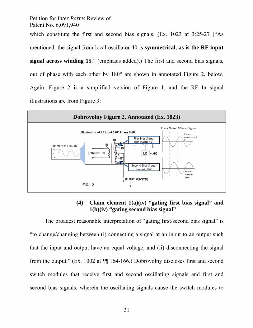
(4) Claim element 1(a)(iv) “gating first bias signal” and
1(b)(iv) “gating second bias signal”
The broadest reasonable interpretation of “gating first/second bias signal” is
“to change/changing between (i) connecting a signal at an input to an output such
that the input and output have an equal voltage, and (ii) disconnecting the signal
from the output.” (Ex. 1002 at ¶¶ 164-166.) Dobrovolny discloses first and second
switch modules that receive first and second oscillating signals and first and
second bias signals, wherein the oscillating signals cause the switch modules to

Petition for Inter Partes Review of Patent No. 6,091,940
32
gate the bias signals.
Dobrovolny Figure 2, annotated below, shows the local oscillator signals
causing the first and second switch modules to alternately gate the first and second
bias signals.
Dobrovolny Figure 2, Annotated (Ex. 1023)
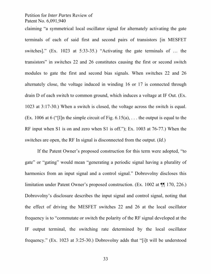
Dobrovolny’s written description reinforces that the oscillating signals cause
the switches 22’ and 26’ in Figure 2 to close at the local oscillator frequency,
which connects and disconnects the RF In signals at the drain D of each switch
with the source S, which is connected to a common ground:
“The MESFETS 22 and 26 are represented by switches 22' and 26',
respectively, and are effective to alternately connect the free terminals
of windings 16 and 17 to ground when the switches 22' and 26' are
closed under control of LO 40, i.e., at the local oscillator
frequency.”
(Ex. 1023 at 3:20-25 (emphasis added).)
Dobrovolny Claim 1 confirms the effect of the local oscillator signals,
Petition for Inter Partes Review of Patent No. 6,091,940
33
claiming “a symmetrical local oscillator signal for alternately activating the gate
terminals of each of said first and second pairs of transistors [in MESFET
switches].” (Ex. 1023 at 5:33-35.) “Activating the gate terminals of … the
transistors” in switches 22 and 26 constitutes causing the first or second switch
modules to gate the first and second bias signals. When switches 22 and 26
alternately close, the voltage induced in winding 16 or 17 is connected through
drain D of each switch to common ground, which induces a voltage at IF Out. (Ex.
1023 at 3:17-30.) When a switch is closed, the voltage across the switch is equal.
(Ex. 1006 at 6 (“[I]n the simple circuit of Fig. 6.15(a), . . . the output is equal to the
RF input when S1 is on and zero when S1 is off.”); Ex. 1003 at 76-77.) When the
switches are open, the RF In signal is disconnected from the output. (Id.)
If the Patent Owner’s proposed construction for this term were adopted, “to
gate” or “gating” would mean “generating a periodic signal having a plurality of
harmonics from an input signal and a control signal.” Dobrovolny discloses this
limitation under Patent Owner’s proposed construction. (Ex. 1002 at ¶¶ 170, 226.)
Dobrovolny’s disclosure describes the input signal and control signal, noting that
the effect of driving the MESFET switches 22 and 26 at the local oscillator
frequency is to “commutate or switch the polarity of the RF signal developed at the
IF output terminal, the switching rate determined by the local oscillator
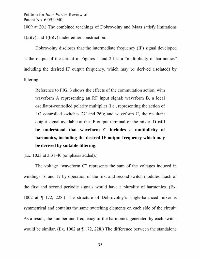
frequency.” (Ex. 1023 at 3:25-30.) Dobrovolny adds that “[i]t will be understood
Petition for Inter Partes Review of Patent No. 6,091,940
34
that waveform C [in Figure 3] includes a multiplicity of harmonics, including the
desired IF output frequency which may be derived by suitable filtering.” (Ex. 1023
at 3:37-40.)
(5) Claim element 1(a)(v) “first periodic signal having a first plurality of harmonics” and 1(b)(v) “second periodic signal having a second plurality of harmonics”
Dobrovolny renders these limitations obvious in view of the teachings of
Maas. Dobrovolny discloses every structural component recited in claim 1 and
further discloses that the claimed single balanced mixer generates a “multiplicity of
harmonics, including the desired IF output frequency which may be derived by
suitable filtering.” (Ex. 1023 at 3:37-40.) Maas complements Dobrovolny’s
teachings by teaching how any mixer (including Dobrovolny’s upconverter) could
be subharmonically pumped to generate desired higher frequency harmonics that
could be isolated to accomplish up-conversion.
In the Related Litigation, Patent Owner proposes a broad construction of
“harmonic,” arguing that “harmonic” is “a frequency or tone that, when compared
to its fundamental or reference, is an integer multiple including the fundamental
(n=1).” (Ex.1008 at 9.) Petitioners’ proposed construction of “harmonic” is “a
frequency or tone that is an integer multiple of the frequency of the oscillating
signal, i.e., if the oscillating signal has a fundamental frequency of ‘f’ then its
harmonics may be located at frequencies of ‘n•f,’ where ‘n’ is 2, 3, 4, etc.” (Ex.
Petition for Inter Partes Review of Patent No. 6,091,940
35
1009 at 20.) The combined teachings of Dobrovolny and Maas satisfy limitations
1(a)(v) and 1(b)(v) under either construction.
Dobrovolny discloses that the intermediate frequency (IF) signal developed
at the output of the circuit in Figures 1 and 2 has a “multiplicity of harmonics”
including the desired IF output frequency, which may be derived (isolated) by
filtering:
Reference to FIG. 3 shows the effects of the commutation action, with
waveform A representing an RF input signal; waveform B, a local
oscillator-controlled polarity multiplier (i.e., representing the action of
LO controlled switches 22' and 26'); and waveform C, the resultant
output signal available at the IF output terminal of the mixer. It will
be understood that waveform C includes a multiplicity of
harmonics, including the desired IF output frequency which may
be derived by suitable filtering.
(Ex. 1023 at 3:31-40 (emphasis added).)
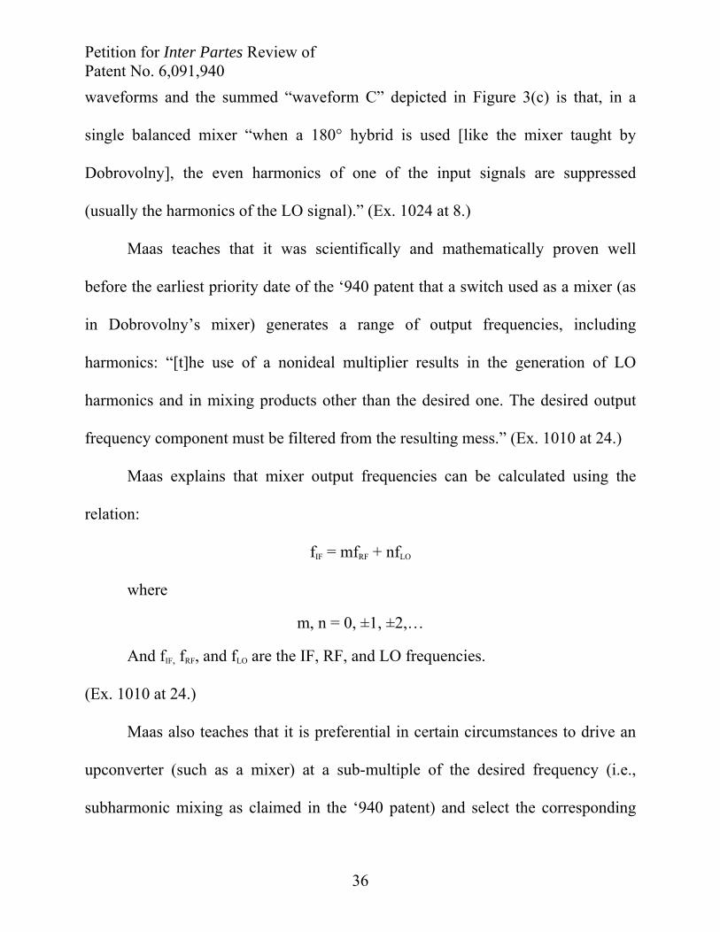
The voltage “waveform C” represents the sum of the voltages induced in
windings 16 and 17 by operation of the first and second switch modules. Each of
the first and second periodic signals would have a plurality of harmonics. (Ex.
1002 at ¶ 172, 228.) The structure of Dobrovolny’s single-balanced mixer is
symmetrical and contains the same switching elements on each side of the circuit.
As a result, the number and frequency of the harmonics generated by each switch
would be similar. (Ex. 1002 at ¶ 172, 228.) The difference between the standalone
Petition for Inter Partes Review of Patent No. 6,091,940
36
waveforms and the summed “waveform C” depicted in Figure 3(c) is that, in a
single balanced mixer “when a 180° hybrid is used [like the mixer taught by
Dobrovolny], the even harmonics of one of the input signals are suppressed
(usually the harmonics of the LO signal).” (Ex. 1024 at 8.)
Maas teaches that it was scientifically and mathematically proven well
before the earliest priority date of the ‘940 patent that a switch used as a mixer (as
in Dobrovolny’s mixer) generates a range of output frequencies, including
harmonics: “[t]he use of a nonideal multiplier results in the generation of LO
harmonics and in mixing products other than the desired one. The desired output
frequency component must be filtered from the resulting mess.” (Ex. 1010 at 24.)
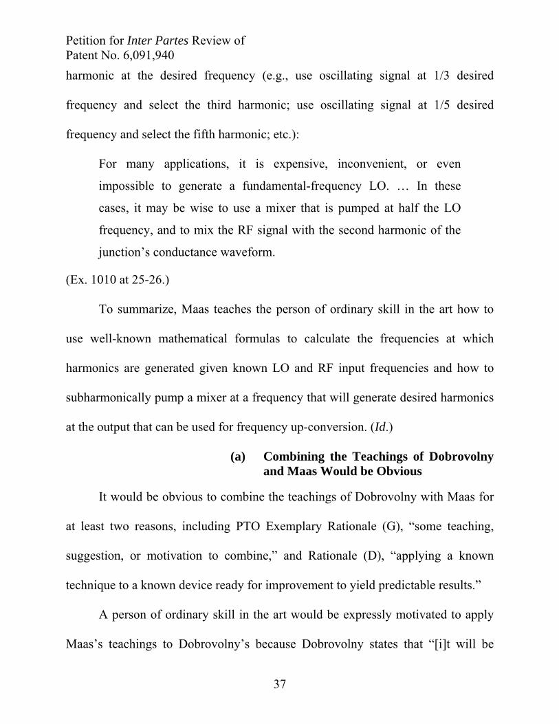
Maas explains that mixer output frequencies can be calculated using the
relation:
fIF = mfRF + nfLO
where
m, n = 0, ±1, ±2,…
And fIF, fRF, and fLO are the IF, RF, and LO frequencies.
(Ex. 1010 at 24.)
Maas also teaches that it is preferential in certain circumstances to drive an
upconverter (such as a mixer) at a sub-multiple of the desired frequency (i.e.,
subharmonic mixing as claimed in the ‘940 patent) and select the corresponding
Petition for Inter Partes Review of Patent No. 6,091,940
37
harmonic at the desired frequency (e.g., use oscillating signal at 1/3 desired
frequency and select the third harmonic; use oscillating signal at 1/5 desired
frequency and select the fifth harmonic; etc.):
For many applications, it is expensive, inconvenient, or even
impossible to generate a fundamental-frequency LO. … In these
cases, it may be wise to use a mixer that is pumped at half the LO
frequency, and to mix the RF signal with the second harmonic of the
junction’s conductance waveform.
(Ex. 1010 at 25-26.)
To summarize, Maas teaches the person of ordinary skill in the art how to
use well-known mathematical formulas to calculate the frequencies at which
harmonics are generated given known LO and RF input frequencies and how to
subharmonically pump a mixer at a frequency that will generate desired harmonics
at the output that can be used for frequency up-conversion. (Id.)
(a) Combining the Teachings of Dobrovolny and Maas Would be Obvious
It would be obvious to combine the teachings of Dobrovolny with Maas for
at least two reasons, including PTO Exemplary Rationale (G), “some teaching,
suggestion, or motivation to combine,” and Rationale (D), “applying a known
technique to a known device ready for improvement to yield predictable results.”
A person of ordinary skill in the art would be expressly motivated to apply
Maas’s teachings to Dobrovolny’s because Dobrovolny states that “[i]t will be
Petition for Inter Partes Review of Patent No. 6,091,940
38
understood that waveform C includes a multiplicity of harmonics, including the
desired IF output frequency, which may be derived by suitable filtering.” (Ex. 1023
at 3:37-40.) In other words, Dobrovolny teaches that one of the multiplicity of
harmonics is the desired IF output frequency, which would motivate a person of
ordinary skill in the art to consult Maas’s teaching how to subharmonically pump
the mixer and mathematically identify a desired harmonic in the mixer output
signal, such as non-suppressed odd-order harmonics where n=3, 5, 7, etc. (Ex.
1002 at ¶¶ 178, 181, 234, 237; MPEP § 2143(g).)
It would also be obvious to apply Maas’s known technique of
subharmonically pumping a mixer to accomplish up-conversion to Dobrovolny’s
known device. Applying Maas’s teachings to Dobrovolny’s mixer would improve
the operation of the mixer and yield predictable results without requiring any
structural modifications in the mixer itself. (Ex. 1002 at ¶ 183-184, 239-240;
MPEP § 2143(d).)
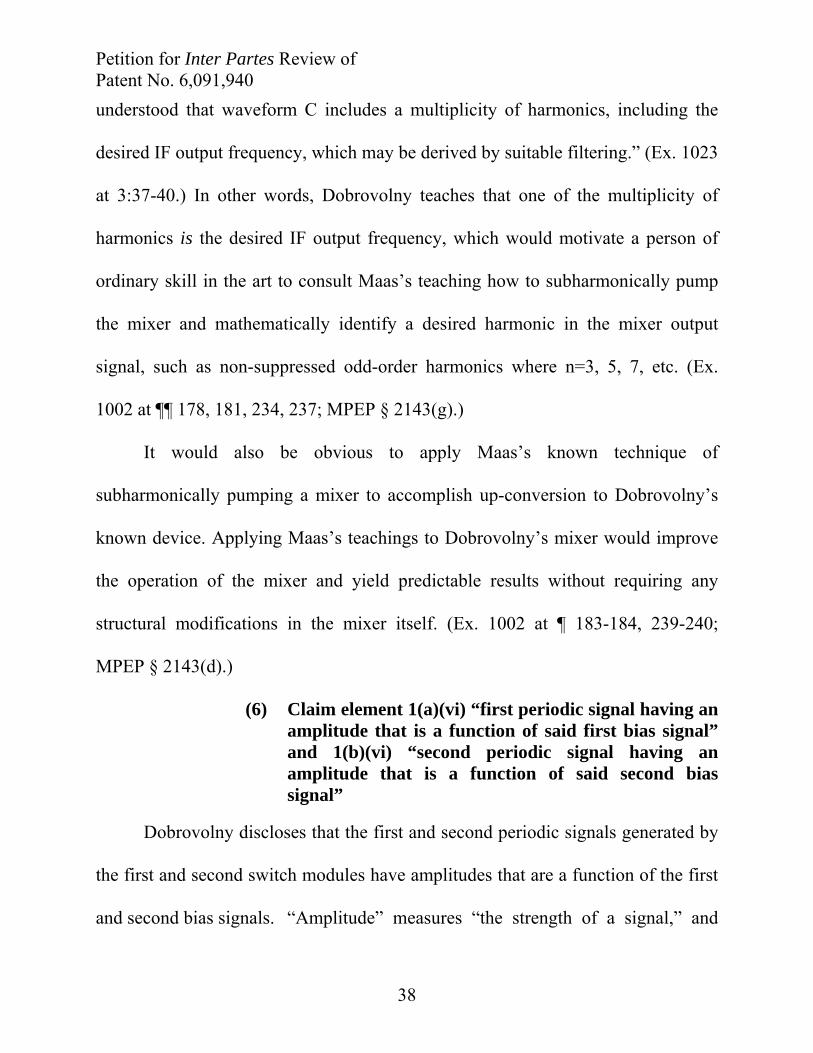
(6) Claim element 1(a)(vi) “first periodic signal having an amplitude that is a function of said first bias signal” and 1(b)(vi) “second periodic signal having an amplitude that is a function of said second bias signal”
Dobrovolny discloses that the first and second periodic signals generated by
the first and second switch modules have amplitudes that are a function of the first
and second bias signals. “Amplitude” measures “the strength of a signal,” and
Petition for Inter Partes Review of Patent No. 6,091,940
39
“can be defined in terms of current, voltage, or power.” (Ex. 1029, Encyclopedia of
Electronics at 6-7.) The amplitudes of the periodic signals that emerge from the
switch modules 22 and 26 are a function of the first and second bias signals
because of the inherent properties of Dobrovolny’s claimed mixer. “Mixers
faithfully preserve the amplitude and phase properties of signals at the RF port.
Signals can therefore be translated in frequency without affecting their modulation
properties.” (Ex. 1026, Vizmuller at 5 (emphasis added).) In other words, as the RF
Design Guide explains, the amplitude of the periodic signals that emerge from the
mixer are functions of the first and second bias signals (the non-inverted and
inverted RF In signals) because the mixer “faithfully preserve[s] the amplitude” of
signals at the RF port (i.e., the bias signals) while up- or down-converting their
frequency. (Id.)
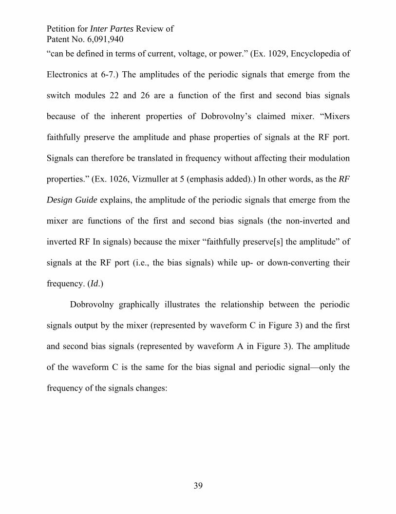
Dobrovolny graphically illustrates the relationship between the periodic
signals output by the mixer (represented by waveform C in Figure 3) and the first
and second bias signals (represented by waveform A in Figure 3). The amplitude
of the waveform C is the same for the bias signal and periodic signal—only the
frequency of the signals changes:
Petition for Inter Partes Review of Patent No. 6,091,940
40
Dobrovolny Figure 3, Annotated (Ex. 1023)
The waveforms of the first and periodic signals alone (i.e., unsummed)
would be identical to waveform C, which is summed, but include even-order
harmonics from the local oscillator signals. (Ex. 1002 at ¶ 189, 245; Ex. 1024 at 8
(“when a 180° hybrid is used [in a single balanced mixer], the even harmonics of
one of the input signals are suppressed (usually the harmonics of the LO signal.”).)
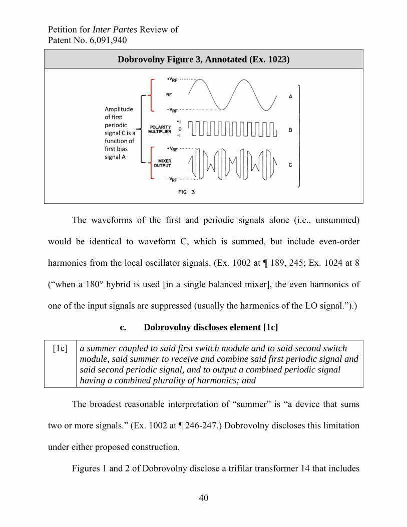
c. Dobrovolny discloses element [1c]
[1c] a summer coupled to said first switch module and to said second switch module, said summer to receive and combine said first periodic signal and said second periodic signal, and to output a combined periodic signal having a combined plurality of harmonics; and
The broadest reasonable interpretation of “summer” is “a device that sums
two or more signals.” (Ex. 1002 at ¶ 246-247.) Dobrovolny discloses this limitation
under either proposed construction.
Figures 1 and 2 of Dobrovolny disclose a trifilar transformer 14 that includes
Petition for Inter Partes Review of Patent No. 6,091,940
41
input winding 15 and a pair of output windings 16 and 17, which connect at center
tap 18 in the secondary of the transformer. (Ex. 1023 at 2:49-3:40; Figs. 1-3.)
Transformer 14 is coupled to switches 22 and 26 and in combination with their
operation, sums the voltages generated by the switches, producing a waveform C at
the IF Out port that includes a multiplicity of harmonics. (Id.) The voltage
summing is equivalent to (1,0,1,0,1…)*Vin + (0,1,0,1,0…)*-Vin, which represents
the sum of voltages on each coil modulated by switching. (Ex. 1002 at ¶ 248.)
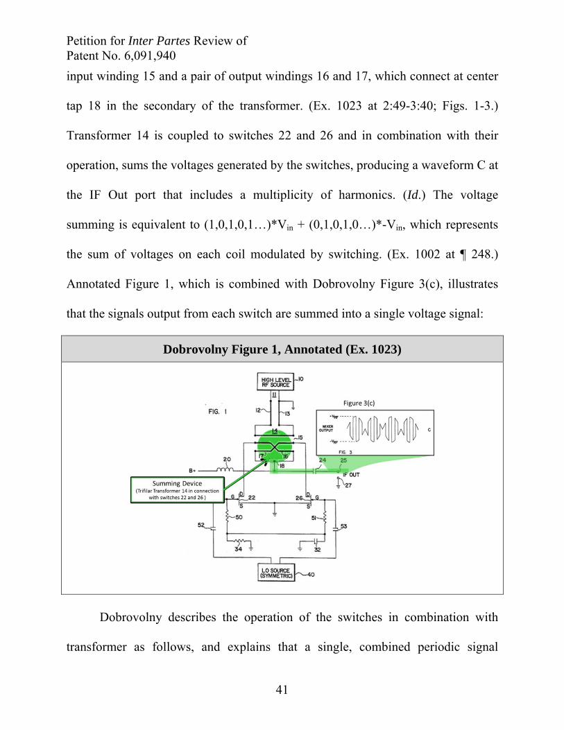
Annotated Figure 1, which is combined with Dobrovolny Figure 3(c), illustrates
that the signals output from each switch are summed into a single voltage signal:
Dobrovolny Figure 1, Annotated (Ex. 1023)
Dobrovolny describes the operation of the switches in combination with
transformer as follows, and explains that a single, combined periodic signal
Petition for Inter Partes Review of Patent No. 6,091,940
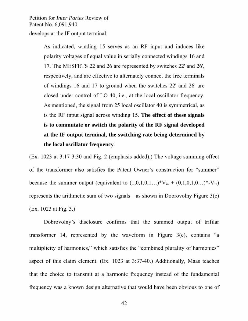
42
develops at the IF output terminal:
As indicated, winding 15 serves as an RF input and induces like
polarity voltages of equal value in serially connected windings 16 and
17. The MESFETS 22 and 26 are represented by switches 22' and 26',
respectively, and are effective to alternately connect the free terminals
of windings 16 and 17 to ground when the switches 22' and 26' are
closed under control of LO 40, i.e., at the local oscillator frequency.
As mentioned, the signal from 25 local oscillator 40 is symmetrical, as
is the RF input signal across winding 15. The effect of these signals
is to commutate or switch the polarity of the RF signal developed
at the IF output terminal, the switching rate being determined by
the local oscillator frequency.
(Ex. 1023 at 3:17-3:30 and Fig. 2 (emphasis added).) The voltage summing effect
of the transformer also satisfies the Patent Owner’s construction for “summer”
because the summer output (equivalent to (1,0,1,0,1…)*Vin + (0,1,0,1,0…)*-Vin)
represents the arithmetic sum of two signals—as shown in Dobrovolny Figure 3(c)
(Ex. 1023 at Fig. 3.)
Dobrovolny’s disclosure confirms that the summed output of trifilar
transformer 14, represented by the waveform in Figure 3(c), contains “a
multiplicity of harmonics,” which satisfies the “combined plurality of harmonics”
aspect of this claim element. (Ex. 1023 at 3:37-40.) Additionally, Maas teaches
that the choice to transmit at a harmonic frequency instead of the fundamental
frequency was a known design alternative that would have been obvious to one of
Petition for Inter Partes Review of Patent No. 6,091,940
43
ordinary skill in the art. (Ex. 1010 at 25 (“In these cases, it may be wise to use a
mixer that is pumped at half the LO frequency, and to mix the RF signal with the
second harmonic of the junction’s conductance waveform.”).) It would therefore
be obvious to a person of ordinary skill in the art to transmit at a harmonic instead
of at the fundamental frequency. (Ex. 1002 at ¶ 240.)
d. Dobrovolny renders obvious element [1d]
[1d] a filter coupled to said summer, said filter to isolate at least one of said combined plurality of harmonics.
Dobrovolny renders this limitation obvious by teaching that “[i]t will be
understood that waveform C includes a multiplicity of harmonics, including the
desired IF output frequency which may be derived by suitable filtering.” (Ex.
1023 at 3:37-40 (emphasis added).) It would be obvious to a person of ordinary
skill in the art how to “suitably filter” the IF output to select the harmonic
containing the “desired IF output frequency.” (Ex. 1002 at ¶ 254.) Maas’s
Microwave Mixers confirms that it “is generally easy” to filter out the desired
output. (Ex. 1010 at 9-10 (“Again, it is generally easy to filter out the desired
difference frequency.”).) In Maas’s discussion of the design of subharmonic
mixers, Maas further notes that it is “rarely difficult to realize” filters for isolating
the desired output of a subharmonic mixer. (Ex. 1010 at 26.) As Dobrovolny
teaches and Maas confirms, filtering the output signal of a mixer required no more
Petition for Inter Partes Review of Patent No. 6,091,940
44
than applying known techniques using known devices to yield predictable results.
MPEP § 2143(d). (Ex. 1002 at ¶ 254.)
2. Claim 18
a. Dobrovolny discloses the preamble [18]
[18] An apparatus for communicating, comprising:
Claim element [18] is identical to claim element [1] discussed above. This
element is disclosed by Dobrovolny for the reasons discussed in Section
IX(A)(1)(a) at page 21 above.
b. Dobrovolny and Maas render obvious elements [18a] and [18b]
[18a] a first switch module to receive a first oscillating signal and a first bias signal, wherein said first oscillating signal causes said first switch module to gate said first bias signal and thereby generate a first periodic signal having a first plurality of harmonics, said first periodic signal having an amplitude that is a function of said first bias signal, said first bias signal being a function of a first information signal;
[18b] a second switch module to receive a second oscillating signal and a second bias signal, wherein said second oscillating signal causes said second switch module to gate said second bias signal and thereby generate a second periodic signal having a second plurality of harmonics, said second periodic signal having an amplitude that is a function of said second bias signal, said second bias signal being a function of a second information signal;
Claim elements [18a] and [18b] are substantively identical to claim elements
[1a] and [1b] discussed above, except for the last clause which recites “said [first] /
[second] bias signal being a function of a first information signal.” All but the
Petition for Inter Partes Review of Patent No. 6,091,940
45
final sub-element of [18a] and [18b] are therefore rendered obvious by the
teachings of Dobrovolny in light of Maas for the reasons discussed in Section
IX(A)(1)(b) beginning at page 22 above. Dobrovolny also discloses the final sub-
element in [18a] and [18b].
(1) Claim element 18(a)(i) “said first bias signal being a function of a first information signal” and 18(b)(i) “said second bias signal being a function of a second information signal”
Dobrovolny discloses first/second bias signals that are a function of first
/second information signals. The ʼ940 patent explains that “[i]t is well known to
those skilled in the relevant art(s) that the information signal 5650 may be used as
the bias/reference signal 5646 directly without being summed with a bias signal.”
(Ex. 1001 at 57:1-4 (emphasis added).) In other words, the ʼ940 patent defines
“bias signal” as encompassing information signals. As explained in Section
IX(A)(1)(b)(3) above, Dobrovolny discloses symmetrical RF In signals that
constitute first and second bias signals because they contain information in the
form of television programming. (Ex. 1023 at 1:14-17.) All persons of skill in the
art understand that the RF In signals disclosed in Dobrovolny are the signals that
contain the information to be received or transmitted. (Ex. 1022 at 36.)
The specification of the ‘940 patent emphasizes that “[i]t is well known to
those skilled in the relevant art(s) that the information signal 5650 may be used as
the bias/reference signal 5646 directly without being summed with a bias signal.”
Petition for Inter Partes Review of Patent No. 6,091,940
46
(Ex. 1001 at 57:1-4.) In RF circuits like Dobrovolny’s in which the information
signal is “used as the bias/reference signal … directly without being summed
with a bias signal” the “bias signal” is necessarily a function of the information
signal. (Ex. 1001 at 57:1-4; Ex. 1002 at ¶ 260-263, 268-271 (emphasis added).)
c. Dobrovolny discloses element [18c]
[18c] a summer coupled to said first switch module and to said second switch module, said summer to receive and combine said first periodic signal and said second periodic signal, and to output a combined periodic signal having a combined plurality of harmonics; and
Claim element [18c] is identical to claim element [1c]. Accordingly, claim
element [18c] is obvious in view of Dobrovolny for the reasons discussed in
Section IX(A)(1)(c) on page 40.
d. Dobrovolny renders obvious element [18d]
[18d] a filter coupled to said summer, said filter to isolate at least one of said combined plurality of harmonics.
Claim element [18d] is identical to claim element [1d]. Accordingly, claim
element [18d] is obvious in view of Dobrovolny for the reasons discussed in
Section IX(A)(1)(d) on page 43.
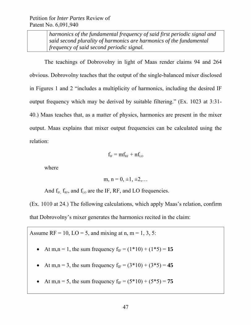
3. Claims 94 and 264
[94] The apparatus of claim 1, wherein said first plurality of harmonics are harmonics of the fundamental frequency of said first periodic signal and said second plurality of harmonics are harmonics of the fundamental frequency of said second periodic signal.
[264] The apparatus of claim 18, wherein said first plurality of harmonics are
Petition for Inter Partes Review of Patent No. 6,091,940
47
harmonics of the fundamental frequency of said first periodic signal and said second plurality of harmonics are harmonics of the fundamental frequency of said second periodic signal.
The teachings of Dobrovolny in light of Maas render claims 94 and 264
obvious. Dobrovolny teaches that the output of the single-balanced mixer disclosed
in Figures 1 and 2 “includes a multiplicity of harmonics, including the desired IF
output frequency which may be derived by suitable filtering.” (Ex. 1023 at 3:31-
40.) Maas teaches that, as a matter of physics, harmonics are present in the mixer
output. Maas explains that mixer output frequencies can be calculated using the
relation:
fIF = mfRF + nfLO
where
m, n = 0, ±1, ±2,…
And fIF, fRF, and fLO are the IF, RF, and LO frequencies.
(Ex. 1010 at 24.) The following calculations, which apply Maas’s relation, confirm
that Dobrovolny’s mixer generates the harmonics recited in the claim:
Assume RF = 10, LO = 5, and mixing at n, m = 1, 3, 5:
At m,n = 1, the sum frequency fIF = (1*10) + (1*5) = 15
At m,n = 3, the sum frequency fIF = (3*10) + (3*5) = 45
At m,n = 5, the sum frequency fIF = (5*10) + (5*5) = 75
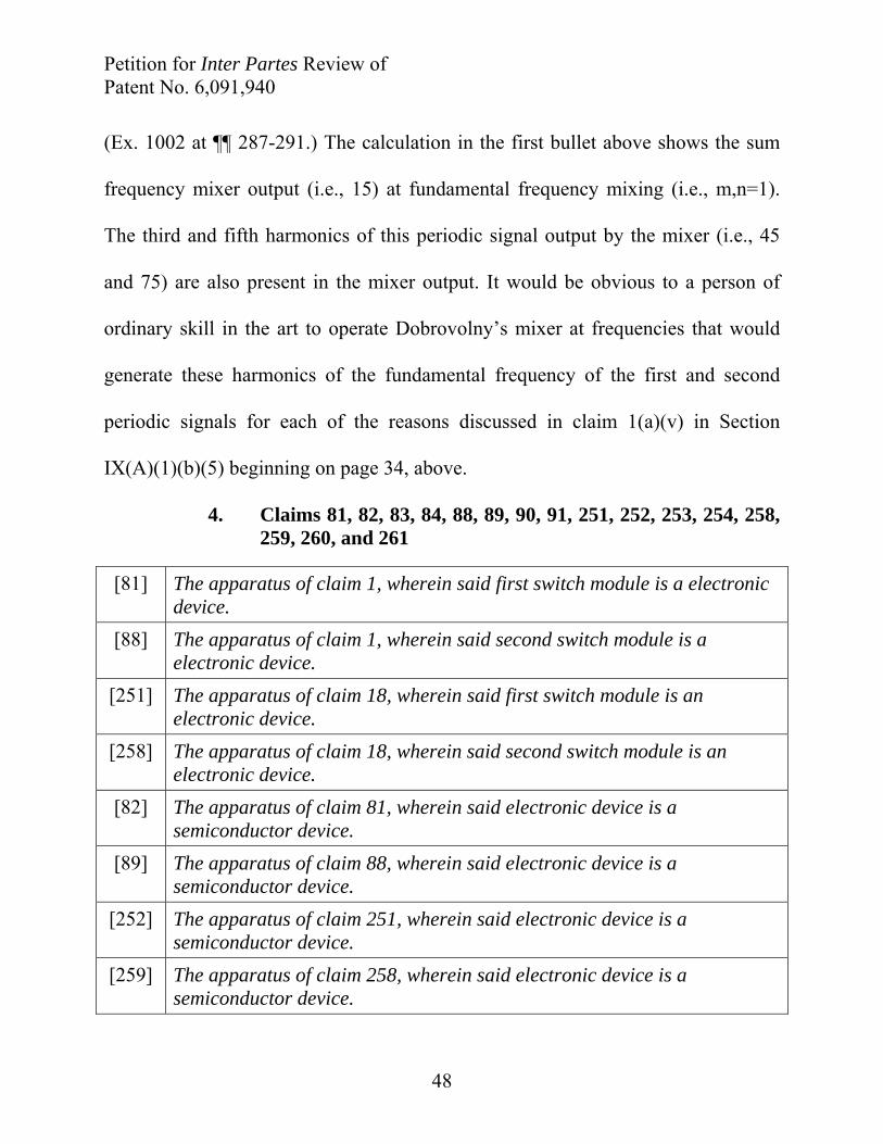
Petition for Inter Partes Review of Patent No. 6,091,940
48
(Ex. 1002 at ¶¶ 287-291.) The calculation in the first bullet above shows the sum
frequency mixer output (i.e., 15) at fundamental frequency mixing (i.e., m,n=1).
The third and fifth harmonics of this periodic signal output by the mixer (i.e., 45
and 75) are also present in the mixer output. It would be obvious to a person of
ordinary skill in the art to operate Dobrovolny’s mixer at frequencies that would
generate these harmonics of the fundamental frequency of the first and second
periodic signals for each of the reasons discussed in claim 1(a)(v) in Section
IX(A)(1)(b)(5) beginning on page 34, above.
4. Claims 81, 82, 83, 84, 88, 89, 90, 91, 251, 252, 253, 254, 258, 259, 260, and 261
[81] The apparatus of claim 1, wherein said first switch module is a electronic device.
[88] The apparatus of claim 1, wherein said second switch module is a electronic device.
[251] The apparatus of claim 18, wherein said first switch module is an electronic device.
[258] The apparatus of claim 18, wherein said second switch module is an electronic device.
[82] The apparatus of claim 81, wherein said electronic device is a semiconductor device.
[89] The apparatus of claim 88, wherein said electronic device is a semiconductor device.
[252] The apparatus of claim 251, wherein said electronic device is a semiconductor device.
[259] The apparatus of claim 258, wherein said electronic device is a semiconductor device.
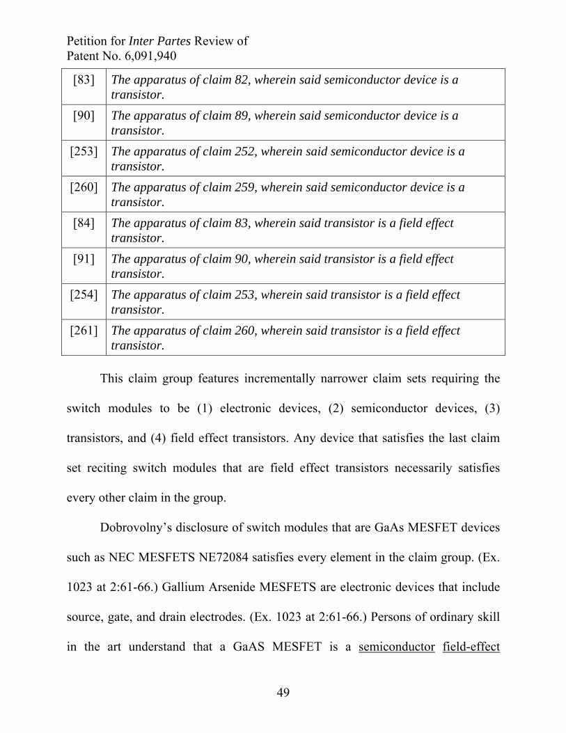
Petition for Inter Partes Review of Patent No. 6,091,940
49
[83] The apparatus of claim 82, wherein said semiconductor device is a transistor.
[90] The apparatus of claim 89, wherein said semiconductor device is a transistor.
[253] The apparatus of claim 252, wherein said semiconductor device is a transistor.
[260] The apparatus of claim 259, wherein said semiconductor device is a transistor.
[84] The apparatus of claim 83, wherein said transistor is a field effect transistor.
[91] The apparatus of claim 90, wherein said transistor is a field effect transistor.
[254] The apparatus of claim 253, wherein said transistor is a field effect transistor.
[261] The apparatus of claim 260, wherein said transistor is a field effect transistor.
This claim group features incrementally narrower claim sets requiring the
switch modules to be (1) electronic devices, (2) semiconductor devices, (3)
transistors, and (4) field effect transistors. Any device that satisfies the last claim
set reciting switch modules that are field effect transistors necessarily satisfies
every other claim in the group.
Dobrovolny’s disclosure of switch modules that are GaAs MESFET devices
such as NEC MESFETS NE72084 satisfies every element in the claim group. (Ex.
1023 at 2:61-66.) Gallium Arsenide MESFETS are electronic devices that include
source, gate, and drain electrodes. (Ex. 1023 at 2:61-66.) Persons of ordinary skill
in the art understand that a GaAS MESFET is a semiconductor field-effect

Petition for Inter Partes Review of Patent No. 6,091,940
50
transistor. (Ex. 1010 at 15-23 (“GaAs MESFET” means “Gallium Arsenide metal
semiconductor field-effect transistor (MESFET);” “The GaAs MESFET is a
junction field-effect transistor (JFET).”; Ex. 1002 at ¶ 283.)
B. Ground 2 – Dobrovolny in light of Maas and Sullivan Render Claims 86, 93, 256, and 263 Obvious Under 35 U.S.C. § 103(a)
[86] The apparatus of claim 84, wherein said field effect transistor is a complementary metal oxide semiconductor field effect transistor.
[93] The apparatus of claim 91, wherein said field effect transistor is a complementary metal oxide semiconductor field effect transistor.
[256] The apparatus of claim 254, wherein said field effect transistor is a complementary metal oxide semiconductor field effect transistor.
[263] The apparatus of claim 261, wherein said field effect transistor is a complementary metal oxide semiconductor field effect transistor.
Claims 86, 93, 256 and 263 are obvious in light of the teachings of
Dobrovolny combined with Maas and Patrick J. Sullivan, et al., Active Doubly
Balanced Mixers for CMDS RFIC's. The teachings of Dobrovolny and Maas
disclose each structure recited in independent claims 1 and 18 from which these
claims depend. Dobrovolny discloses a mixer that uses MESFET switches. (Ex.
1023 at 2:60-64.) Sullivan teaches that, “[t]he similarities between MOSFET and
MESFET devices allow the designer to apply the extensive knowledge of
MESFET mixers to the design of MOSFET mixers.” (Ex.1005 at 1.) And Sullivan
explains that he successfully built CMOS-FET mixers: “Two fully integrated
doubly balanced CMOS mixers have demonstrated the ability of a standard CMOS
Petition for Inter Partes Review of Patent No. 6,091,940
51
process to operate at commercial wireless frequency bands with reasonable
dynamic range. . . . The dynamic range and port-to-port isolation make doubly
balanced CMOS mixers suitable for downconverter and upconverter applications
in an all-CMOS transceiver.” (Ex. 1005 at 9.)
A person of ordinary skill would be motivated to combine the teachings of
Dobrovolny and Sullivan to use CMOS-FET switches in a mixer like
Dobrovolny’s. (MPEP § 2143(g); Ex. 1002 at ¶¶ 285-286). Sullivan provides a
suggestion and motivation for combining its teachings with Dobrovolny’s by
explaining that existing CMOS infrastructure supported the development of low
cost, mast-produced integrated circuits:
Using CMOS technology, RF designers can utilize the large
infrastructure in place that supports and develops low cost, mass-
produced ICs. The drive to increase transceiver integration and reduce
transceiver cost makes CMOS an attractive technology for low cost,
highly integrated transceivers.
(Ex. 1005 at 9.) Sullivan’s teachings would have led one of ordinary skill to
modify Dobrovolny’s teachings to utilize CMOS-FET switches because Sullivan
teaches that CMOS-FET switches are “an attractive technology” alternative to
MESFETs for designers seeking to build “low cost, highly integrated transceivers.”
(Ex. 1002 at ¶ 286.) All commercial RF circuit designers sought to build “low cost,
highly integrated transceivers” because integration and cost reduction are two main
Petition for Inter Partes Review of Patent No. 6,091,940
52
drivers of electronic circuit designs. (Ex. 1022 at 7-8 (“in addition, digital
communications techniques can exploit the relentless advance of digital integrated
circuit (IC) technology to realize improved functionality at lower power dissipation
and lower cost.”).)
C. No Secondary Considerations of Non-Obviousness Exist
Petitioners are unaware of any objective evidence of non-obviousness of the
Petitioned Claims. Petitioners respectfully reserve the right to rebut any alleged
evidence of non-obviousness identified in Patent Owner’s Response.
X. CONCLUSION
Petitioners respectfully request institution of inter partes review of claim 1
and its dependent claims 81-84, 86, 88-91, 93, and 94, and claim 18 and its
dependent claims 251-54, 256, 258-61, 263, and 264 of the ’940 patent, and a
finding that the claims are unpatentable as obvious under 35 U.S.C. § 103(a).

Petition for Inter Partes Review of Patent No. 6,091,940
53
Dated: August 28, 2015 COOLEY LLP ATTN: Patent Group 1299 Pennsylvania Ave., NW, Suite 700 Washington, DC 20004 Tel: (703) 456-8000 Fax: (202) 842-7899
Respectfully submitted, COOLEY LLP
By: /Timothy S. Teter/ Timothy S. Teter Reg. No. 47,134
Petition for Inter Partes Review of Patent No. 6,091,940
54
CERTIFICATE OF SERVICE
Pursuant to 37 C.F.R. §§ 42.6(e) and 42.105(b), the undersigned certifies
that on August 28, 2015, a complete and entire copy of this Petition for Inter
Partes Review of Patent No. 6,091,940, including Exhibit Nos. 1001-1035 and a
Power of Attorney, was served via FEDERAL EXPRESS, costs prepaid, to the
Patent Owner by serving the correspondence address of record as follows:
Workman Nydegger 60 East South Temple, Suite 1000 Salt Lake City, UT 84111 Counsel of Record for Patent Owner Parkervision, Inc.
and, upon counsel of record for the Patent Owner in the litigation pending before
the U.S. District Court for the Middle District of Florida entitled ParkerVision, Inc.
v. Qualcomm Incorporated, et al., No. 6:14-cv-00687-PGB-KRS (M.D. Fla.) as
follows:
Douglas Aaron Cawley Richard Kamprath McKool Smith, PC 300 Crescent Court, Suite 1500 Dallas, TX 75201 Attorneys for Plaintiff ParkerVision, Inc.
Jennifer A. Albert Joshua W. Budwin Kevin L. Burgess Mario A. Apreotesi Leah Buratti Kathi Li Puneet Kohli McKool Smith, PC 300 West 6th Street, Suite 1700 Austin, TX 78701 Attorneys for Plaintiff ParkerVision, Inc.
Petition for Inter Partes Review of Patent No. 6,091,940
55
James Arthur Bolling Stephen D. Busey Smith, Hulsey & Busey 225 Water Street, Suite 1800 PO Box 53315 Jacksonville, FL 32202-3315 Attorneys for Plaintiff ParkerVision, Inc.
Dated: August 28, 2015
COOLEY LLP ATTN: Timothy S. Teter Patent Docketing 1299 Pennsylvania Ave. NW, Suite 700 Washington, D.C. 20004 Tel: (650) 843-5000 Fax: (202) 842-7899
/Timothy S. Teter/ Timothy S. Teter Reg. No. 47,134
120662764 v7