personal - University of Kansaspeople.ku.edu/~z190z415/publications/phf2010.pdf · ·...
15
Nonlinear spacing and frequency effects of an oscillating cylinder in the wake of a stationary cylinder Xiaofan Yang and Zhongquan Charlie Zheng a Department of Mechanical and Nuclear Engineering, Kansas State University, Manhattan, Kansas 66506, USA Received 25 November 2009; accepted 16 February 2010; published online 7 April 2010 Nonlinear responses to a transversely oscillating cylinder in the wake of a stationary upstream cylinder are studied theoretically by using an immersed-boundary method at Re= 100. Response states are investigated in the three flow regimes for a tandem-cylinder system: the “vortex suppression” regime, the critical spacing regime, and the “vortex formation” regime. When the downstream cylinder is forced to oscillate at a fixed frequency and amplitude, the response state of flow around the two cylinders varies with different spacing between the two cylinders, while in the same flow regime, the response state can change with the oscillating frequency and amplitude of the downstream cylinder. Based on velocity phase portraits, each of the nonlinear response states can be categorized into one of the three states in the order of increasing chaotic levels: lock-in, transitional, or quasiperiodic. These states can also be correlated with velocity spectral behaviors. The discussions are conducted using near-wake velocity phase portraits, spectral analyses, and related vorticity fields. A general trend in the bifurcation diagrams of frequency spacing shows the smaller the spacing, frequency, or amplitude, the less chaotic the response state of the system and more likely the downstream and upstream wakes are in the same response state. The system is not locked-in in any case when the spacing between the cylinders is larger than the critical spacing. The near-wake velocity spectral behaviors correspond to the nonlinear response states, with narrow-banded peaks shown at the oscillation frequency and its harmonics in the lock-in cases. High frequency harmonic peaks, caused by interactions between the upstream wake and the downstream oscillating cylinder, are reduced in the near-wake velocity spectra of the upstream cylinder when the spacing increases. © 2010 American Institute of Physics. doi:10.1063/1.3372169 I. INTRODUCTION Wake-structure interactions among oscillating tandem cylinders can be found in many engineering applications, such as arrays of tubes in heat exchangers, power lines, and off-shore engineering structures. It is a complicated problem because the behavior of this nonlinear system depends on a combination of parameters related to both oscillating mo- tions and tandem arrangement. This creates many nonlinear physical phenomena that are of interest to those who re- search fluid dynamics. The purpose of this study was to in- vestigate how spacing and frequency influence the nonlinear behaviors of flow around the two cylinders when the down- stream cylinder oscillates transversely. This study extends the current findings in the literature. 1–3 Papaioannou et al. 1 investigated the holes in the Arnold tongues of flow past two oscillating cylinders that oscillate simultaneously at the same amplitude and frequency. Karniadakis and Triantafyllou 2 and Zheng and Zhang 3 studied the nonlinear and frequency lock-in behaviors of a single oscillating cylinder for different frequencies and amplitudes. Historically, a simpler version of the problem—the re- sponse of a single circular cylinder oscillating in a uniform stream—has been studied extensively using experimental measurements and numerical simulations. 4–6 Detailed mechanisms of this problem have also been reviewed. 7 Fur- thermore, a new development in the numerical schemes for computational studies of flow over a two-dimensional oscil- lating cylinder has been recently reported. 2,3,8,9 In these stud- ies, almost every aspect in the single cylinder with/without external forcing—from vortex formation VF and wake structures to frequency selection and response states—has been investigated thoroughly. The literature concerning flow over two stationary tan- dem cylinders includes experimental observations 7,10,11 and numerical simulations. 12–15 Physical mechanisms involved in two tandem cylinders are very different from those in a single cylinder because the wakes that are shed from both cylinders are coupled and interact with each other. The vor- ticity field is significantly affected by the Reynolds number Re= UD / and the spacing between the two cylinders. As confirmed in the literature 13 and this study, the Strouhal num- ber St= fD / U of the two tandem cylinders is not the same as that of the single cylinder for the same Reynolds number. In addition, the Strouhal number is identical for both of the cylinders in the system. Compared with single stationary cyl- inder cases, which are mostly dominated by Reynolds num- bers, the spacing effect of the tandem cylinders is another important factor. It has been found that by changing the dis- tance between the two cylinders wake formation and cou- pling may vary. Most interestingly, there exists a critical a Electronic mail: [email protected]. PHYSICS OF FLUIDS 22, 043601 2010 1070-6631/2010/224/043601/15/$30.00 © 2010 American Institute of Physics 22, 043601-1 author's personal copy
Transcript of personal - University of Kansaspeople.ku.edu/~z190z415/publications/phf2010.pdf · ·...
Nonlinear spacing and frequency effects of an oscillating cylinderin the wake of a stationary cylinder
Xiaofan Yang and Zhongquan Charlie Zhenga�
Department of Mechanical and Nuclear Engineering, Kansas State University,Manhattan, Kansas 66506, USA
�Received 25 November 2009; accepted 16 February 2010; published online 7 April 2010�
Nonlinear responses to a transversely oscillating cylinder in the wake of a stationary upstreamcylinder are studied theoretically by using an immersed-boundary method at Re=100. Responsestates are investigated in the three flow regimes for a tandem-cylinder system: the “vortexsuppression” regime, the critical spacing regime, and the “vortex formation” regime. When thedownstream cylinder is forced to oscillate at a fixed frequency and amplitude, the response state offlow around the two cylinders varies with different spacing between the two cylinders, while in thesame flow regime, the response state can change with the oscillating frequency and amplitude of thedownstream cylinder. Based on velocity phase portraits, each of the nonlinear response states can becategorized into one of the three states in the order of increasing chaotic levels: lock-in, transitional,or quasiperiodic. These states can also be correlated with velocity spectral behaviors. Thediscussions are conducted using near-wake velocity phase portraits, spectral analyses, and relatedvorticity fields. A general trend in the bifurcation diagrams of frequency spacing shows the smallerthe spacing, frequency, or amplitude, the less chaotic the response state of the system and morelikely the downstream and upstream wakes are in the same response state. The system is notlocked-in in any case when the spacing between the cylinders is larger than the critical spacing. Thenear-wake velocity spectral behaviors correspond to the nonlinear response states, withnarrow-banded peaks shown at the oscillation frequency and its harmonics in the lock-in cases. Highfrequency harmonic peaks, caused by interactions between the upstream wake and the downstreamoscillating cylinder, are reduced in the near-wake velocity spectra of the upstream cylinder when thespacing increases. © 2010 American Institute of Physics. �doi:10.1063/1.3372169�
I. INTRODUCTION
Wake-structure interactions among oscillating tandemcylinders can be found in many engineering applications,such as arrays of tubes in heat exchangers, power lines, andoff-shore engineering structures. It is a complicated problembecause the behavior of this nonlinear system depends on acombination of parameters related to both oscillating mo-tions and tandem arrangement. This creates many nonlinearphysical phenomena that are of interest to those who re-search fluid dynamics. The purpose of this study was to in-vestigate how spacing and frequency influence the nonlinearbehaviors of flow around the two cylinders when the down-stream cylinder oscillates transversely. This study extendsthe current findings in the literature.1–3 Papaioannou et al.1
investigated the holes in the Arnold tongues of flow past twooscillating cylinders that oscillate simultaneously at the sameamplitude and frequency. Karniadakis and Triantafyllou2 andZheng and Zhang3 studied the nonlinear and frequencylock-in behaviors of a single oscillating cylinder for differentfrequencies and amplitudes.
Historically, a simpler version of the problem—the re-sponse of a single circular cylinder oscillating in a uniformstream—has been studied extensively using experimental
measurements and numerical simulations.4–6 Detailedmechanisms of this problem have also been reviewed.7 Fur-thermore, a new development in the numerical schemes forcomputational studies of flow over a two-dimensional oscil-lating cylinder has been recently reported.2,3,8,9 In these stud-ies, almost every aspect in the single cylinder with/withoutexternal forcing—from vortex formation �VF� and wakestructures to frequency selection and response states—hasbeen investigated thoroughly.
The literature concerning flow over two stationary tan-dem cylinders includes experimental observations7,10,11 andnumerical simulations.12–15 Physical mechanisms involved intwo tandem cylinders are very different from those in asingle cylinder because the wakes that are shed from bothcylinders are coupled and interact with each other. The vor-ticity field is significantly affected by the Reynolds number�Re=UD /�� and the spacing between the two cylinders. Asconfirmed in the literature13 and this study, the Strouhal num-ber �St= fD /U� of the two tandem cylinders is not the sameas that of the single cylinder for the same Reynolds number.In addition, the Strouhal number is identical for both of thecylinders in the system. Compared with single stationary cyl-inder cases, which are mostly dominated by Reynolds num-bers, the spacing effect of the tandem cylinders is anotherimportant factor. It has been found that by changing the dis-tance between the two cylinders wake formation and cou-pling may vary. Most interestingly, there exists a criticala�Electronic mail: [email protected].
PHYSICS OF FLUIDS 22, 043601 �2010�
1070-6631/2010/22�4�/043601/15/$30.00 © 2010 American Institute of Physics22, 043601-1
autho
r's pe
rsona
l cop
y

spacing distance �Sc� on the border of the VF and vortexsuppression �VS� regimes, which is marked by a suddenjump and discontinuity of the Strouhal number. For lowReynolds number laminar cases �in the range of 100 s�, thecritical spacing is predicted by Li et al.12 to be between 3 and4 and by Sharman et al.13 to be between 3.75 and 4.
The literature concerning oscillating cylinders in the tan-dem arrangement is relatively scarce. Li et al.16 studied nu-merically an oscillating cylinder in uniform flow and in thewake of an upstream stationary cylinder using a finite-element method. They mimicked the oscillation effect of thedownstream cylinder by defining a sinusoidal velocity on itssurface without moving the second cylinder, so that a fixedgrid mesh could be used. The investigation of oscillatingtandem cylinder cases was focused on only one spacing inthe VF regime in that study. More recently, Papaioannouet al.1 investigated the holes in the Arnold tongues of flowpast two oscillating cylinders following the experimental evi-dence observed by Mahir and Rockwell.17 The Arnoldtongue indicates the lock-in regions in the amplitude versusfrequency diagrams. It was first proven to exist in the experi-ment by Ongoren and Rockwell.18 They studied the responsestates of a closely spaced tandem oscillating cylinders over acertain range of external forcing frequencies. The lock-inregion was found to be wider than that of a single cylinder.Similar results were shown by Papaioannou et al.1 using nu-merical simulations. At Re=160, they placed two cylindersnear each other and oscillated under the same amplitude andfrequency with either the same or opposite phase, and theshape of the Arnold tongue was clearly shown in their study.Several types of nonlinearity appeared in the velocity phaseportrait, from lock-in, quasiperiodic, and transitional to pe-riod doubling. They also studied two spacing distances �2.5and 3.5� that could be related to the critical and VF regimescorrespondingly, with a restriction of both of the cylindersoscillating at the same amplitude and frequency. The spacingand frequency effects on nonlinear behavior of a tandem cyl-inder system with two cylinders are therefore the focus of thecurrent study that includes all of the three regimes of VS,critical, and VF regimes. It should also be noted that becausethe two cylinders in the current study are not in the sameoscillating motion, many aspects of flow are different fromthose in Papaioannou et al.1 A primary difference is that theflow field behind the first cylinder can be very different fromthat behind the second cylinder in both frequency responseand phase portrait. We found new vortex structures in thewake related to different nonlinear response states.
While the response of a tandem cylinder system to acontrolled oscillating downstream cylinder with a prescribedfrequency is studied in the paper, there are many practicalapplications on flow around self-oscillating cylinders due tovortex-induced vibration.19–21 However, under certain condi-tions, some of the flow behaviors in controlled vibration canbe very close to those in free vibration.22,23
The numerical scheme of the immersed-boundarymethod �IBM� is explained in Sec. II. In Sec. III, the flowpatterns of a system of two stationary cylinders at differentspacing and the related Strouhal number effect are described.
A detailed discussion on the oscillating downstream cylindercases is presented in Sec. IV, and the conclusions are made inSec. V.
II. NUMERICAL SIMULATION
Direct numerical simulations based on an improved IBMwith direct forcing24 are carried out to simulate the flowsystem. The nondimensionalized governing equations usingthe characteristic parameters of �, U, and D for two-dimensional, laminar, incompressible flow are
� · u = 0 �1�
and
�u
�t+ u · �u = − �P +
1
Re�2u + f , �2�
where Re is defined as UD /�, with U the uniform incomingvelocity, D the cylinder diameter, and � the kinematic vis-cosity. A Re of 100 is used for this study. The boundaryforcing term f is applied on an internal layer of the immersedboundary and calculated at each time step to obtain the de-sired boundary velocity by using the formula
f = S + �P −1
Re�2u +
1
�t�v − u� , �3�
where v is the desired velocity and S is the convection termdefined as S= �u ·��u. The internal layer is a layer of gridpoints that are immediately interior to each of the cylindersurface boundaries.
The momentum equation, Eq. �2�, is solved using asecond-order differencing scheme on a staggered Cartesiangrid, which includes a semi-implicit scheme for the diffusionterm �with the normal direction diffusion terms being theCrank–Nicholson scheme�, the Adams–Bashforth scheme forthe convection, and second-order central differencing for dif-fusion. The incompressibility condition, Eq. �1�, is satisfiedby solving a Poisson equation for pressure correction usingFISHPACK. The overall accuracy of the scheme is able toreach the second order. More details concerning the modifiedIBM can be found in Zhang and Zheng.24
When the IBM is used, arbitrary shapes and motions ofsolid bodies can be effectively simulated by a proper con-struction of the boundary forcing term so that a simple, non-moving Cartesian grid can be used. The domain size selectedfor this study is 38.4�25.6, as shown in Fig. 1. The up-
8
38.4
25.6
S
U∝ u = U∝v = 0
∂u/∂x = 0∂v/∂x = 0
∂u/∂y = 0 v = 0
∂u/∂y = 0 v = 0
0.8D 0.8D
0.8
D
P2P1
0.8
D
x
y
FIG. 1. Computational domain, boundary conditions, and near-wake veloc-ity probing points.
043601-2 X. Yang and Z. C. Zheng Phys. Fluids 22, 043601 �2010�
autho
r's pe
rsona
l cop
y

stream cylinder is located at 8, sufficiently away from theinlet boundary to eliminate the inlet effect. The distance be-tween the two cylinders is defined as S �nondimensionalizedby the cylinder diameter D�. The outlet boundary is also farenough from the downstream cylinder to allow the vortexstreet to develop fully. The grid-size independence check24
determined that a grid size with �x=�y=0.025 provides anacceptable grid resolution for all the computational cases atRe=100. The boundary conditions are also shown in Fig. 1.For a stationary cylinder, the velocity on the surface is zero.For a transversely oscillating cylinder, the displacement iscalculated as
dy = A sin�2�t � fc� , �4�
where A �nondimensionalized by D� is the amplitude of thedisplacement, fc is the forcing frequency, and t is the time.The time step size is computed from different forcing fre-quencies as �t=1 / fcN, where N is the number of time stepswithin one oscillation period. Moreover, the size of the timestep must also satisfy the stability criterion of an explicitscheme for a two-dimensional convection-diffusion equation,that is, �t�min�h2 Re /4,2 / �u2+v2�Re�, where h is the gridsize.
The computational scheme has been verified with nu-merous experimental and computational data.24 For example,for flow over a single oscillating cylinder, the computationalresults at various forcing frequencies were shown in Zhengand Zhang,3 where both frequency lock-in and non-lock-incases were identified using time histories and power spectraof lift and drag, and good agreements were achieved in com-parison to literature data.5,6,9,18 These examples have pro-vided sufficient validations for the computational schemeused in our study.
In order to justify the two-dimensional flow assumptionin this study, we have tested three-dimensional simulation atRe=100 with a periodic boundary condition in the cylinderaxial direction. By examining the vorticity contours and ve-locity field in several cutting planes perpendicular to the cyl-inder axial direction, we have found that the flow remainstwo dimensional, with the variation range of these variablesless than 1% along the axial direction. We also increasedReynolds number to 160, which is a case that was treated astwo-dimensional tandem cylinders,1,15 and the three dimen-sionality started to show. Oscillation of the downstream cyl-inder does not enhance the three-dimensional effect much.Therefore, it is expected that the Reynolds number for flowto become three dimensional could be lower in a tandemcylinder system than that in a single cylinder system �whereRe=188.5 �Ref. 25��, with a possibility that oscillation couldfurther reduce that Reynolds number. Considering the stabi-lizing and destabilizing effects of the downstream cylinder,15
this Reynolds number may also vary with the separation dis-tance between the two cylinders. Although for the purpose ofthis study we do not intend to determine this Reynolds num-ber, based on our simulation this Reynolds number canpossibly be below 160. Also, the case we study here atRe=100 is still within a safe range for flow to be two dimen-sional, hence formation due to instability in the axial direc-tion is not considered.26
III. FLOW PATTERNS FOR FLOWOVER TWO STATIONARY TANDEM CYLINDERS
Complicated flow patterns in a stationary tandem cylin-der system have been demonstrated in the literature.7,10,11,13
Basically, the flow patterns can be divided into two regimesby a “critical spacing” �Sc�. In the case of Re=100, the valueof Sc is between 3.75 and 4, according to Sharman et al.13
The different types of vortex streets are shown in the vortic-ity contours for Re=100 in Fig. 2. When S�Sc �S=2 in Fig.2�, the flow is in a regime called the “VS regime,” in whichthe wakes behind both cylinders are rather weak, and there isalmost no vortex shedding, neither in between nor behind thecylinders other than a low-frequency wavy flow pattern inthe wake. The downstream cylinder is so close to the up-stream one that formation of vortices is hindered. The shearlayer from the upstream cylinder does not have sufficientroom to form shed vortices, although there is no precise re-lation between the VF length in the wake of a single cylinderand the critical spacing of a tandem cylinder system.15 Thestabilized wake behind the upstream cylinder �in the sense ofa Hopf bifurcation25�, due to the closeness of the downstreamcylinder, further stabilizes the wake from the second cylinderso that there is no clear vortex shedding even in the wake
(a)
(b)
(c)
FIG. 2. �Color online� Vorticity field for a stationary tandem cylinder systemat three different spacing distances: �a� S=2 �VS�, �b� S=4 �critical�, and �c�S=6 �VF�.
043601-3 Nonlinear spacing and frequency effects Phys. Fluids 22, 043601 �2010�
autho
r's pe
rsona
l cop
y

after the downstream cylinder. When approaching the criticalspacing, the vortex shedding upstream to the second cylinderis intermittent. After a transient period, at S=Sc �S=4 in Fig.2�, a synchronized vortex street is formed eventually behindthe downstream cylinder, and a sudden jump in the Strouhalnumber �St= fD /U� for the cylinder system occurs, althoughthere is still no clear vortex shedding between the cylinders.It should be noted that this Strouhal number is for the entiretandem cylinder system and includes interference effectsamong the two cylinders and their wakes, which is not thesame as that for a single cylinder. This sudden jump is in-dicative that the spacing is reaching the critical spacing.When S�Sc �S=6 in Fig. 2�, the flow is in the “VF regime,”in which synchronized vortex shedding occurs and well de-veloped vortices are shed from the upstream cylinder andreattach themselves to the downstream one. The sheddingvortices behind the first cylinder join those from the down-stream cylinder to form a coupled vortex street in the wakeof the tandem cylinder system.
Figure 3 shows the computed Strouhal number versusthe spacing distance at Re=100 and two other Reynoldsnumbers at 80 and 160 for comparison. The reason to end atRe=160 is because of three dimensionality at high Reynoldsnumber flow stated in Sec. II. On the other hand, at furtherlower Reynolds numbers, such as Re=50 as we tested, theflow is at the verge of being a steady state with a long wakeformation length for a single cylinder case. The possible sta-bilizing effect of the downstream cylinder can make the floweven more stable, and therefore the VF regime is large andno vortex shedding is shown in this regime. In our compu-tation, the Strouhal number is calculated after the periodicvortex streets are formed and the solution converges to astate that shows periodic oscillations. The average surfacepressure coefficient history, during the periods after a con-verged solution �80 or 160 depending on the frequency res-olution needed� is established, is then used for spectral
analysis to determine the Strouhal number. Our St values atRe=100 fit between those reported by Sharman et al.13 andLi et al.12 The sudden jump of the Strouhal number occurs atS=4 in all of the three data sets. For another Reynolds num-ber of 80, we also repeated the same procedure and obtainedthe critical spacing around 5.5, as shown in Fig. 3, whichagrees well with the result by Tanida et al.,11 but is differentfrom the value of 3.7 reported by Li et al.16 One of thereasons could be the resolutions of the grid mesh. As for thesingle cylinder case with Re=100, a relatively coarse meshwas used by Li et al.16 that gave the value of St as 0.166, abit lower than the usual value of 0.17 reported in the litera-ture. Another reason could be due to different definitions ofthe critical spacing. There are several different ways of de-termining the critical spacing in the literature. We define thecritical spacing by observing the sudden increase in theStrouhal number, which is the same definition as what usedby Sharman et al.13 In Li et al.16 the wake length change asan indicator of separate flow regimes was used, while inTanida et al.11 the interference drag was used as the criterion.
IV. SPACING AND FREQUENCY EFFECTSOF A TRANSVERSELY OSCILLATING DOWNSTREAMCYLINDER
Oscillations of the downstream cylinder create morecomplicated nonlinear behaviors and add two more param-eters to the stationary tandem cylinder system: the frequencyand the amplitude of the oscillating downstream cylinder. Inthis study, we investigated different oscillating frequencies atvarious spacings under relatively small amplitudes. It shouldbe noted that oscillations of cylinder do not alter the spacingrange significantly in distinguishing the VS and VF regimes,as long as the oscillation amplitude is small such as those inthis study. In terms of phase portrait of velocity field, in astationary tandem cylinder system there is always a “lock-in”type in the phase portrait of both downstream and upstreamwakes, since there is only one major characteristic frequencyin the system corresponding to the Strouhal number of thestationary tandem system.
In the following discussions, we analyze nonlinear be-haviors for each case �at a specific spacing, frequency, andamplitude� in three ways: �1� phase portrait plots to analyzethe nonlinear dynamic mechanism; �2� power spectral analy-ses to reveal frequency effects; and �3� vorticity contourplots to explain the flow physics and vortex patterns.
Velocity histories are recorded at two points that are both0.8D downstream of the center of each cylinder and 0.8Dabove the center line in the transverse direction �P1 and P2shown in Fig. 1�. These points are in the near-wake regionand thus the effects from vortex shedding and oscillations ofthe cylinder can be easily detected. For P1, we can detect thebehaviors in the wake of the upstream cylinder, while for P2,the merging effect of the vortex streets of the two cylinderscan be seen. Power spectral analyses are carried out using thehistories of streamwise velocity in the last several periods.The dominant frequencies in the spectra can be used as oneof the indicators for classifying the nonlinear response states.In the phase portrait plots, the trajectories of time histories of
Spacing (S)
Str
ouha
lnum
ber
(St)
1 2 3 4 5 6 7 80.1
0.12
0.14
0.16
0.18
0.2
Papaioannou et al 2006b, Re = 160current scheme, Re = 160Li et al, 1991, Re = 100Sharman et al, 2005, Re = 100current scheme, Re = 100current scheme, Re = 80
FIG. 3. �Color online� Comparisons of Strouhal number prediction for astationary tandem cylinder system at different spacing distances �S� andReynolds numbers of 80, 100, and 160.
043601-4 X. Yang and Z. C. Zheng Phys. Fluids 22, 043601 �2010�
autho
r's pe
rsona
l cop
y

the streamwise �u� and the transverse �v� velocity compo-nents are mapped into the u-v plane to identify the limitcycles for characterizing responses of the nonlinear systemunder forcing. For the problems of flow over cylinders, phaseportraits of velocity have been used to categorize nonlinearresponse states.1,2,16
In this study, the spacing between the two cylinders isconsidered a major factor that influences system behaviors,which differs from a previous study1 where frequency andamplitude were the main factors. At one oscillating fre-quency, under different spacing distances, the resulting flowpatterns change. On the other hand, how the flow patternsvary with the oscillating frequencies is also highly influencedby the spacing distance between the two cylinders. Here westudy three spacing distances of S=2, 4, and 6, which corre-spond to the VS, critical, and VF flow regimes in the station-ary tandem cylinder case, as discussed in Sec. III. For eachof the spacing S, six different oscillating frequencies weretested: natural vortex shedding frequency �fns�, two nearbyfrequencies �fc=0.9fns ,1.1fns�, and three higher-frequencyexcitations �fc=1.3fns ,1.5fns ,1.7fns�. The oscillating dis-placement amplitude A was fixed at two relatively small val-ues of 0.15 and 0.35.
It should be noted that the natural frequency here, fns, isthe same as the Strouhal number of the corresponding sta-tionary tandem cylinder system, a term also used in theliterature.1 In this study, the intention is to investigate theresponse of the system to oscillations in the vicinity of thisfrequency. Therefore, the oscillation frequency fc is scaledby the natural frequency.1 This natural frequency changeswith the spacing between the two cylinders, as shown in Fig.3, because the system characteristics change.
In this discussion, we first give an overall picture of thenonlinear behaviors of the system by showing bifurcationdiagrams of normalized frequency �with respect to the corre-sponding natural frequency� versus spacing in Figs. 4 and 5,drawn from the cases of different combinations of abovementioned parameters. The diagrams categorize all the casesinto three states or classes: lock-in, transitional, and quasip-eriodic, the same three classes used by Papaioannou et al.1
However, unlike the study by Papaioannou et al.1 in whichthe cylinders have the same motion �although either perfectlyin phase or in opposite phase�, we have one forced oscillat-ing cylinder and one stationary cylinder. We also distinguish,with filled or hollow symbols, whether there are peaks athigh frequencies in the velocity spectra detected in the wakebehind the upstream cylinder, a feature that is shown in thestreamwise velocity spectra in Figs. 6 and 7 and will befurther discussed in Secs. IV A–IV C. In addition, we inspectboth the velocities behind the upstream cylinder �at P1� andthe downstream cylinder �at P2� because flow in the down-stream wake may not necessarily behave the same way as itdoes in the upstream wake. According to the results to bediscussed later, the flow patterns in the two wakes can belongto different categories among the three states. Even whenflows at P1 and P2 are in the same state, differences in spec-tra still exist. It is physically plausible that the upstream anddownstream flows can be in the same class because of theincompressible, elliptic-type domain of influence, particu-
larly when the spacing distance between the two cylinders issmall. However, differences in flow features also exist due todifferent wakes behind the upstream cylinder with respect toeach of the flow regimes. Particularly, if the distance be-tween the two cylinders is sufficiently large, the differencesare more likely to occur.
The general trend illustrated in the diagrams shows thatthe smaller the spacing, frequency, and amplitude, the morelikely the system is locked-in, and thus the bifurcation dia-grams of frequency spacing do not form Arnold tongues. Bycomparing Fig. 4�a� with Fig. 4�b� and Fig. 5�a� with Fig.5�b�, we see that it is more likely that the upstream wake anddownstream wake are in the same flow pattern class whenthe spacing is smaller and excitation frequency is lower. Inaddition, no high-frequency peaks appear in the upstreamwake in the non-lock-in cases at the critical spacing and inall cases at the VF spacing. As long as the flow state is alock-in, the upstream high-frequency peaks remain. Thehigh-frequency peaks in the downstream wake are generatedby interactions between the upstream wake and the oscillat-
Spacing (S)
Fre
que
ncy
(fc/
fns)
1 2 3 4 5 6 70.8
0.9
1
1.1
1.2
1.3
1.4
1.5
1.6
1.7
1.8
(a)
Spacing (S)
Fre
que
ncy
(fc/
fns)
1 2 3 4 5 6 70.8
0.9
1
1.1
1.2
1.3
1.4
1.5
1.6
1.7
1.8
(b)
FIG. 4. Response state diagrams of spacing vs frequency for probed veloci-ties in the wake of each of the cylinders at A=0.15. �a� Upstream cylinder;�b� downstream cylinder. Triangle: lock-in; square: transitional; circle: qua-siperiodic. The filled symbols indicate that wake velocity spectra of theupstream cylinder lose peaks at high frequencies.
043601-5 Nonlinear spacing and frequency effects Phys. Fluids 22, 043601 �2010�
autho
r's pe
rsona
l cop
y

ing downstream cylinder. This explains why the high-frequency peaks no longer exist in the upstream wake atsome critical and all VF spacing, because such interactionsonly weakly affect the upstream wake when the spacing islarge. At the VS spacing, as the two cylinders are very close,the oscillatory flow effect due to the oscillating downstreamcylinder is very strong, leading to high-frequency peaks inall the VS �S=2� cases. At the VF spacing, high-frequencypeaks disappear in the upstream wake in all of the cases,while at the critical spacing, only the two lock-in cases at thelower amplitude in Fig. 4 do not show this phenomenon.Changing amplitudes does not affect either the VS cases orthe VF cases, but does affect significantly the critical spacingcases, resulting in no lock-in for all the critical spacing casesat the larger amplitude. Therefore, critical spacing �S=4� issensitive to excitation amplitude, which leads lock-in andtransitional cases at the lower amplitude to either transitionalor quasiperiodic at the higher amplitude. In a large spacingsystem of VF �S=6� cases, the upstream wake remains tran-sitional and the downstream wake remains quasiperiodic, re-gardless of the frequency or the amplitude of the excitation.We also studied the state bifurcation diagrams for a lowerReynolds number case at Re=80 �in which case the criticalspacing is at S=5.5, as discussed in Sec. III�, and they are all
in the same general trend as in the above descriptions forRe=100.
Upon further inspection of the detailed frequency re-sponse behaviors at each spacing distance, we find that thespectral contents of near-field velocity histories, Figs. 6 and7, can also be linked to the three states as �1� for lock-in,there is a clear, narrow-banded dominant peak at fc and itsharmonics; �2� for transitional, there is a major, relativelybroadband peak close to fc or fns, and other peaks are in ascattered and insignificant manner; and �3� for quasiperiodic,there are peaks at both fc and fns, and also peaks at theirrespective harmonics.
In Secs. IV A–IV C, we look into the frequency responsebehaviors presented in power spectrum plots at each spacingdistance along with the phase portrait plots to confirm thecompatibility among them in terms of classifying the re-sponse states. Furthermore, corresponding vortex sheddingpatterns in vorticity contour plots are also discussed in thecontext of response states.
A. The VS spacing, S=2
At the VS spacing �S=2�, the two cylinders are in a veryclose arrangement. Unless the amplitude is sufficiently high,the existence of the downstream cylinder hinders the devel-opment of vortex shedding in the wake of the upstream cyl-inder. The wake of the upstream cylinder is “forced” to os-cillate with that of the downstream cylinder, resulting in thesame response between the two wakes. Furthermore, as flowoscillations in the VS cases are closely coupled between theupstream and downstream regions, the flow is locked-in in awide frequency range, and flow patterns behind the two cyl-inders fall into the same flow class. The entire tandem cyl-inder system is thus similar to a single bluff body underoscillatory excitations. In the frequency-spacing diagrams inFigs. 4 and 5, at 0.9fns to 1.3fns, pure lock-in responses exist,which break down to quasiperiodic states at higher frequen-cies. The two different amplitudes result in the same type ofresponses, and increasing the amplitude further may breakdown lock-in at a lower frequency.
When flow is locked in, significant peaks appear at theexcitation frequency and its superharmonics. For example, inthe case of fc=1.3fns, one dominant peak appears at 1.3fns inthe wake behind each cylinder, as shown in Figs. 6 and 7.There are no peaks at either fns or its superharmonics. A limitcycle of a single closed orbit in Figs. 8�a� and 8�b� is re-peated in time in the velocity phase portrait plots for bothupstream and downstream wakes, indicating a pure lock-infor flow around both cylinders. Note that the numbers onboth the abscissa and ordinate of all the phase portraits inthis paper are in the unit of dimensionless velocity. Since thissystem behaves similarly to a single oscillating bluff body,vorticity contours in Fig. 8�c� show a typical 2S vortex shed-ding structure �Ref. 5�, in which each positive vortex is fol-lowed by a negative vortex behind the downstream cylinder.This vortex shedding pattern was also observed3 for singleoscillating cylinder cases in the lock-in regime.
For frequencies higher than 1.3fns, the excitation fre-quency fc is away from the natural frequency fns. The re-
Spacing (S)
Fre
que
ncy
(fc/
fns)
1 2 3 4 5 6 70.8
0.9
1
1.1
1.2
1.3
1.4
1.5
1.6
1.7
1.8
(a)
Spacing (S)
Fre
que
ncy
(fc/
fns)
1 2 3 4 5 6 70.8
0.9
1
1.1
1.2
1.3
1.4
1.5
1.6
1.7
1.8
(b)
FIG. 5. Same as in Fig. 4 but with A=0.35.
043601-6 X. Yang and Z. C. Zheng Phys. Fluids 22, 043601 �2010�
autho
r's pe
rsona
l cop
y

sponse state first changes to a transitional state when domi-nant peaks start to appear at frequencies either fc or fns, orbetween the two, and then the state turns to quasiperiodic inwhich significant peaks appear at both fc and fns and their
superharmonics. However, as the entire flow field is closelysynchronized, the near wakes behind the upstream anddownstream cylinders are again in the same flow class. Welook at the case of fc=1.7fns, A=0.15 as an example of the
log
|u|
0.25 0.5 0.75 110-4
10-3
10-2
10-1
100
101 S4 upS4 down
<
S41.1fnsu&d
S4shifted fnsu&d
f
log|
u|
0.25 0.5 0.75 110-8
10-6
10-4
10-2
100S2 upS2 down
<
S21.1fnsu&d
f
log|
u|
0.25 0.5 0.75 110-4
10-3
10-2
10-1
100 S6 upS6 down
<
S61.3fnsd
S6fnsu&d
f
log|
u|
0.25 0.5 0.75 110-4
10-3
10-2
10-1
100 S6 upS6 down
<
S61.3fnsu&d
S6fnsu&d
f
log
|u|
0.25 0.5 0.75 1
10-3
10-2
10-1
100 S4 upS4 down
<
S41.3fnsu&d
S4fnsu&d
f
log|
u|0.25 0.5 0.75 1
10-8
10-6
10-4
10-2
100 S2 upS2 down
<
S21.3fnsu&d
f
log|
u|
0.25 0.5 0.75 110-4
10-3
10-2
10-1
100 S6 upS6 down
<
S6a peak between0.9fns and fnsu&d
f
log
|u|
0.25 0.5 0.75 110-610-510-410-310-210-1100 S4 up
S4 down<
S40.9fnsu&d
f
log|
u|0.25 0.5 0.75 1
10-8
10-6
10-4
10-2
100 S2 upS2 down
<
S20.9fnsu&d
f
log
|u|
0.25 0.5 0.75 110-8
10-6
10-4
10-2
100 S4 upS4 down
<
S4fnsu&d
f
log|
u|
0.25 0.5 0.75 110-510-410-310-210-1100 S6 up
S6 down<
S6fnsu&d
f
log|
u|
0.25 0.5 0.75 110-9
10-7
10-5
10-3
10-1S2 upS2 down
<
S2fnsu&d
f
(b)(a)
(c) (d)
log|
u|
0.25 0.5 0.75 110-4
10-3
10-2
10-1
100 S6 upS6 down
<
S61.5fnsu&d
S6fnsu&d
f
log
|u|
0.25 0.5 0.75 110-4
10-3
10-2
10-1
100 S4 upS4 down
<
S41.5fnsu&d
S4fnsu&d
f
log|
u|
0.25 0.5 0.75 110-6
10-4
10-2
100 S2 upS2 down
<
S2fnsu&d
S21.5fnsu&d
f
log|
u|
0.25 0.5 0.75 1
10-3
10-2
10-1
100 S6 upS6 down
<
S6fnsu&d
S61.7fnsu&d
f
log
|u|
0.25 0.5 0.75 110-5
10-4
10-3
10-2
10-1
100 S4 upS4 down
<
S41.7fnsu&d
S4fnsu&d
f
log|
u|
0.25 0.5 0.75 110-610-510-410-310-210-1100 S2 up
S2 down<
S2fnsu&d
S21.7fnsu&d
f
(f)(e)
FIG. 6. �Color online� Velocity power spectra at the two locations P1 �upstream, dash line� and P2 �downstream, solid line� with primary peaks pointed outeither at the upstream spectrum �u� or downstream spectrum �d� or both �u and d�. Excitation amplitude A=0.15 with different excitation frequencies at �a�fc=0.9fns, �b� fc= fns, �c� fc=1.1fns, �d� fc=1.3fns, �e� fc=1.5fns, and �f� fc=1.7fns.
043601-7 Nonlinear spacing and frequency effects Phys. Fluids 22, 043601 �2010�
autho
r's pe
rsona
l cop
y

quasiperiodic situation. In Fig. 6, the spectra show that bothupstream and downstream wakes have peaks at identical fre-quencies of fc and fns and their superharmonics, whichmeans that the flow in both regions is quasiperiodic. In Figs.9�a� and 9�b�, the velocity phase portrait plots also display a
quasiperiodic pattern. However, in the vorticity contours inFig. 9�c�, the downstream far wake still develops into a 2Svortex structure. In the near wake the 2S structure is differ-ent, where positive and negative vortices are not shed one byone but form two parallel rows. This behavior still belongs to
log|
u|
0.25 0.5 0.75 110-3
10-2
10-1
100 S6 upS6 down
<
S6fnsu&d
S60.9fnsd
f
log
|u|
0.25 0.5 0.75 1
10-3
10-2
10-1
100 S4 upS4 down
<
S4fnsd
S40.9fnsu&d
f
log|
u|0.25 0.5 0.75 1
10-610-510-410-310-210-1100 S2 up
S2 down<
S20.9fnsu&d
f
log
|u|
0.25 0.5 0.75 1
10-510-410-310-210-1100 S4 up
S4 down<
S4fnsu&d
f
log|
u|
0.25 0.5 0.75 110-4
10-3
10-2
10-1
100 S6 upS6 down
<
S6fnsu&d
f
log|
u|
0.25 0.5 0.75 110-710-610-510-410-310-210-1100 S2 up
S2 down<
S2fnsu&d
f
log
|u|
0.25 0.5 0.75 110-5
10-4
10-3
10-2
10-1
100 S4 upS4 down
<
S41.3fnsu&d
S4fnsu&d
f
log|
u|
0.25 0.5 0.75 1
10-3
10-2
10-1
100 S6 upS6 down
<
S61.3fnsu&d
S6fnsu&d
f
log|
u|0.25 0.5 0.75 1
10-7
10-5
10-3
10-1S2 upS2 down
<
S21.3fnsu&d
f
log|
u|
0.25 0.5 0.75 1
10-3
10-2
10-1
100 S6 upS6 down
<
S6fnsu&d
S61.1fnsd
f
log
|u|
0.25 0.5 0.75 110-3
10-2
10-1
100 S4 upS4 down
<
S41.1fnsd
S4fnsu&d
f
log|
u|
0.25 0.5 0.75 110-7
10-5
10-3
10-1S2 upS2 down
<
S21.1fnsu&d
flo
g|u
|
0.25 0.5 0.75 110-3
10-2
10-1
100 S4 upS4 down
<
S41.7fnsu&d
S4fnsu&d
f
log|
u|
0.25 0.5 0.75 110-5
10-4
10-3
10-2
10-1
100 S2 upS2 down
<
S2fnsu&d
S21.7fnsu&d
f
log|
u|
0.25 0.5 0.75 1
10-3
10-2
10-1
100 S6 upS6 down
<
S6fnsu&d
S61.7fnsu&d
f
log
|u|
0.25 0.5 0.75 110-3
10-2
10-1
100 S4 upS4 down
<
S41.5fnsu&d
S4fnsu&d
f
log|
u|
0.25 0.5 0.75 110-3
10-2
10-1
100 S6 upS6 down
<
S61.5fnsu&d
S6fnsu&d
f
log|
u|
0.25 0.5 0.75 110-4
10-3
10-2
10-1
100 S2 upS2 down
<
S2fnsu&d
S21.5fnsu&d
f
(b)(a)
(c) (d)
(f)(e)
FIG. 7. �Color online� Same as in Fig. 6, but excitation amplitude A=0.35, with the same excitation frequencies at �a� fc=0.9fns, �b� fc= fns, �c� fc=1.1fns, �d�fc=1.3fns, �e� fc=1.5fns, and �f� fc=1.7fns.
043601-8 X. Yang and Z. C. Zheng Phys. Fluids 22, 043601 �2010�
autho
r's pe
rsona
l cop
y

X-velocity
Y-v
eloc
ity
0.9 0.91 0.92 0.93 0.94
0.05
0.055
0.06
0.065
X-velocity
Y-v
elo
city
0.5 0.6 0.7 0.8 0.9-0.25
-0.2
-0.15
-0.1
-0.05
0
0.05
(b)(a)
(c)
FIG. 8. �Color online� The VS case of S=2, fc=1.3fns, and A=0.15. �a� Phase portrait plot �upstream cylinder�, �b� phase portrait plot �downstream cylinder�,�c� vorticity contour plot.
X-velocity
Y-v
eloc
ity
0.82 0.84 0.86 0.88 0.9
0.05
0.06
0.07
0.08
X-velocity
Y-v
eloc
ity
0.5 0.6 0.7
-0.08
-0.04
0
0.04
(b)(a)
(c)
FIG. 9. �Color online� The VS case of S=2, fc=1.7fns, and A=0.15. �a� Phase portrait plot �upstream cylinder�, �b� phase portrait plot �downstream cylinder�,�c� vorticity contour plot.
043601-9 Nonlinear spacing and frequency effects Phys. Fluids 22, 043601 �2010�
autho
r's pe
rsona
l cop
y

X-velocity
Y-v
eloc
ity
0.8 0.81 0.82 0.83 0.840.07
0.075
0.08
0.085
0.09
X-velocity
Y-v
eloc
ity
0.4 0.5 0.6 0.7 0.8 0.9
-0.25
-0.2
-0.15
-0.1
-0.05
0
0.05
(b)(a)
(c)
FIG. 10. �Color online� The critical spacing case of S=4, fc=0.9fns, and A=0.15. �a� Phase portrait plot �upstream cylinder�, �b� phase portrait plot�downstream cylinder�, �c� vorticity contour plot.
X-velocity
Y-v
eloc
ity
0.8 0.9 1 1.1
-0.1
-0.05
0
0.05
0.1
X-velocity
Y-v
eloc
ity
0 0.3 0.6 0.9
-0.4
-0.2
0
0.2
0.4
(b)(a)
(c)
FIG. 11. �Color online� The critical spacing case of S=4, fc=0.9fns, A=0.35. �a� Phase portrait plot �upstream cylinder�, �b� phase portrait plot �downstreamcylinder�, �c� vorticity contour plot.
043601-10 X. Yang and Z. C. Zheng Phys. Fluids 22, 043601 �2010�
autho
r's pe
rsona
l cop
y

the 2S structure. However, in order to distinguish it from atypical 2S vortex street, we name it 2S�. The somewhat or-ganized vortex structures are not typical for a quasiperiodiccase in which a more chaotic flow field is usually expected.
Similarity between a VS tandem cylinder system with adownstream oscillating cylinder and a single oscillating cyl-inder is also evident in the velocity phase portrait plots. Weused cases reported by Zheng and Zhang3 as examples tocompare. In their study, a uniform flow passes a single cyl-inder that oscillates with the same displacement function asEq. �4� at a Reynolds number of 200, while other parametersremain the same as in this study. We compared near-wakevelocity phase portraits of lock-in and non-lock-in single cyl-inder oscillations with those corresponding lock-in and non-lock-in VS cases here. We found that for the lock-in singlecylinder oscillation cases, the phase portraits had a similarorbital trace as the VS lock-in cases, such as those shown inFig. 8, while the single cylinder non-lock-in cases had simi-lar chaotic and disordered phase portrait plots as the non-lock-in VS case in Fig. 9.
With respect to effect of different oscillating amplitudeson flow behavior, our study shows that increasing the oscil-lating amplitude from 0.15 to 0.35 does not change the fre-quency responses and other flow features at the VS spacing.This is compatible with Fig. 1�c� in Ref. 1, which also showsthat the system stays locked-in under a broad range of oscil-lating amplitudes.
B. The critical spacing, S=4
Unlike the VS cases, at this spacing, the system becomesmore sensitive and easier to change from lock-in to otherstates. Because of this spacing, the vortex wake from theupstream cylinder is at the beginning of being fully devel-oped. In the frequency versus spacing diagrams in Figs. 4and 5, under A=0.15, three kinds of frequency responses allappear, and when the amplitude is increased to 0.35, nolock-in cases occur whatsoever. In the two lock-in cases, theresponse states of the upstream and downstream cylindersare still the same, as in the VS lock-in cases. However, whenthe system is not locked-in, different responses occur in thenear wakes of the two cylinders, which is not the case as inthe close spacing VS cases.
In a lock-in case with the critical spacing, such asA=0.15 and 0.9fns, the frequency response of velocity spec-tra behaves the same as those of all the VS lock-in cases, asevident in Figs. 6 and 7. That is, as shown in Fig. 6�a� forS=4, only major peaks appear at the excitation frequencyand their harmonics in the velocity spectra of both cylinders.Because of the same spectral behavior, the phase portraitsand vorticity contours of a lock-in case with the critical spac-ing in Fig. 10 are also very similar to those of the VS lock-oncases, such as those shown in Fig. 8: the phase portraits ofvelocity at P1 and P2 are clearly single close orbits, and thedownstream vortex street has the 2S pattern. In this case ofthe critical spacing with A=0.15 and 0.9fns, the upstream
X-velocity
Y-v
eloc
ity
0.8 0.9 1 1.1-0.09
-0.06
-0.03
0
0.03
0.06
0.09
X-velocity
Y-v
eloc
ity
0.2 0.4 0.6 0.8 1
-0.45
-0.3
-0.15
0
0.15
0.3
(b)(a)
(c)
FIG. 12. �Color online� The critical spacing case of S=4, fc=1.3fns, and A=0.15. �a� Phase portrait plot �upstream cylinder�, �b� phase portrait plot�downstream cylinder�, �c� vorticity contour plot.
043601-11 Nonlinear spacing and frequency effects Phys. Fluids 22, 043601 �2010�
autho
r's pe
rsona
l cop
y

X-velocity
Y-v
eloc
ity
0.8 0.9 1 1.1-0.1
-0.05
0
0.05
0.1
X-velocity
Y-v
eloc
ity
0 0.3 0.6 0.9-0.6
-0.3
0
0.3
0.6
(b)(a)
(c)
FIG. 13. �Color online� The critical spacing case of S=4, fc=1.3fns, and A=0.35. �a� Phase portrait plot �upstream cylinder�, �b� phase portrait plot�downstream cylinder�, �c� vorticity contour plot.
X-velocity
Y-v
eloc
ity
0.9 1 1.1
-0.04
0
0.04
0.08
X-velocity
Y-v
eloc
ity
0.2 0.4 0.6 0.8
-0.3
-0.2
-0.1
0
0.1
0.2
0.3
(b)(a)
(c)
FIG. 14. �Color online� The VF case of S=6, fc=1.3fns, A=0.15. �a� Phase portrait plot �upstream cylinder�, �b� phase portrait plot �downstream cylinder�, �c�vorticity contour plot.
043601-12 X. Yang and Z. C. Zheng Phys. Fluids 22, 043601 �2010�
autho
r's pe
rsona
l cop
y

wake between the two cylinders does not yet develop clearvortex shedding, and therefore even vorticity contours of thewake behind the upstream in Fig. 10�c� look similar to thosein Fig. 8�c�.
If we increase the amplitude to 0.35, the system is nolonger locked-in at any excitation frequency. In the powerspectrum plots for S=4 at 0.9fns in Fig. 7�a�, a dominantpeak at the excitation frequency of 0.9fns still exists in theupstream wake, absent any clearly significant peaks at itsharmonics. This type of non-lock-in spectra was also discov-ered by Karniadakis and Triantafyllou2 for a single oscillat-ing cylinder case as a flow state between the states occurringin lock-in and non-lock-in cases. When we look at the cor-responding velocity phase portraits in Fig. 11�a�, they are nolonger single orbits but multiple loops instead, although theyare not totally chaotic. This shows that this state is not faraway from the state in a lock-in case, and the flow with thistype of phase portraits is categorized as transitional by Ref.1. It should be noted that in all the lock-in cases, steep �nar-row band�, significant peaks appear at the excitation fre-quency as well as its harmonics. The upstream wake has onemore interesting feature: no peaks appear at high frequen-cies. The absence of peaks at higher frequencies in the ve-locity spectra of the upstream wake occurs in all the non-lock-in cases for larger spacing with S=4 and S=6. Thereason, as stated earlier, is because the high-frequency peaksin the downstream wake are generated by interactions be-tween the upstream wake and the oscillating downstreamcylinder, and such interactions only have weak influences onthe upstream wake when the spacing is large. For the down-stream wake in this case, as shown in Fig. 7�a�, a peak alsoappears at the natural frequency fns in addition to the peakthat appears at the excitation frequency of 0.9fns, and peaksappear at the harmonics of these two frequencies. Therefore,the velocity phase portraits in Fig. 11�b� show a more cha-otic, quasiperiodic response state.
We can now compare the flow structures at the two am-plitudes at 0.9fns, one a lock-in case �A=0.15� and the othera transitional case �A=0.35�. For A=0.15 in Fig. 10�c�, noclear vortex shedding occurs in the wake of the upstreamcylinder, and the vortex street in the wake of the downstream
cylinder is a 2S structure. For A=0.35 in Fig. 11�c�, vortexshedding starts to appear in the upstream wake. The down-stream near wake is 2S, and changes to 2S� in the far wake.The 2S structures are typical in lock-in and transitionalstates, and not so much in quasiperiodic states, as evident inother studies.1,2
Increasing excitation frequency to 1.1fns and higherleads to non-lock-in states for all the cases of S=4. ForA=0.15 in Fig. 4, the upstream wake goes through a transi-tional state at fc=1.1,1.3,1.5fns to a quasiperiodic state atfc=1.7fns, while the downstream wake reaches a quasiperi-odic state directly starting at fc=1.1fns. We use fc=1.3fns asan example. The velocity phase portraits in Figs. 12�a� and12�b� show that the upstream wake and downstream wakeare in different response states: the former is transitional andthe latter quasiperiodic. The power spectra in Fig. 6�d� showthat two major peaks coexist at fns and 1.3fns in the down-stream spectrum �the solid black curve�, while one signifi-cant but not so narrow-banded peak appears at fns in theupstream wake spectrum. In addition, the upstream wakespectrum does not acquire high frequency peaks as thedownstream spectrum does. The vorticity field still shows a2S+2S� structure in Fig. 12�c�, which is not much differentfrom the lock-in case of fc=0.9fns, A=0.15.
At A=0.35 and fc=1.3fns, both the downstream and up-stream wakes are in quasiperiodic states. In Fig. 7�d�, peaksat fns and fc�=1.3fns� coexist in both the upstream and down-stream wakes. In this case, although the upstream phase por-trait in Fig. 13�a� shows an orbital behavior that can beviewed as being close to a transitional state, the spectrum isthus used to identify it as a quasiperiodic state. Like otherphase portraits in the paper, this behavior of the phaseportraits is processed based on the result of a long-timesimulation until the solution converges to a state that showsperiodic oscillations. In this case, the vorticity field, the2S+2S� structure in Fig. 13�c�, also does not differ muchfrom that of the lock-in cases. The high-frequency peaksshown in the downstream wake are still absent in the up-stream wake.
TABLE I. Vortex shedding patterns at A=0.15.
0.9fns fns 1.1fns 1.3fns 1.5fns 1.7fns
S2 2S 2S 2S 2S 2S� ,2S 2S� ,2S
S4 2S 2S 2S,2S� 2S,2S� 2S,2S� 2S,2S�
S6 S+P,2S� 2S� 2S� ,S+P,2S 2S� ,S+P,2S 2S� ,S+P,2S 2S�
TABLE II. Vortex shedding patterns at A=0.35.
0.9fns fns 1.1fns 1.3fns 1.5fns 1.7fns
S2 2S 2S 2S 2S 2S� ,2S 2S� ,S+P,2S
S4 2S,2S� 2S 2S,2S� 2S,S+P 2S,2S� ,S+P 2S,2S�
S6 2S� ,2S S+P,2S 2S� ,2S S+P,2S 2S� ,2S S+P,2S
043601-13 Nonlinear spacing and frequency effects Phys. Fluids 22, 043601 �2010�
autho
r's pe
rsona
l cop
y
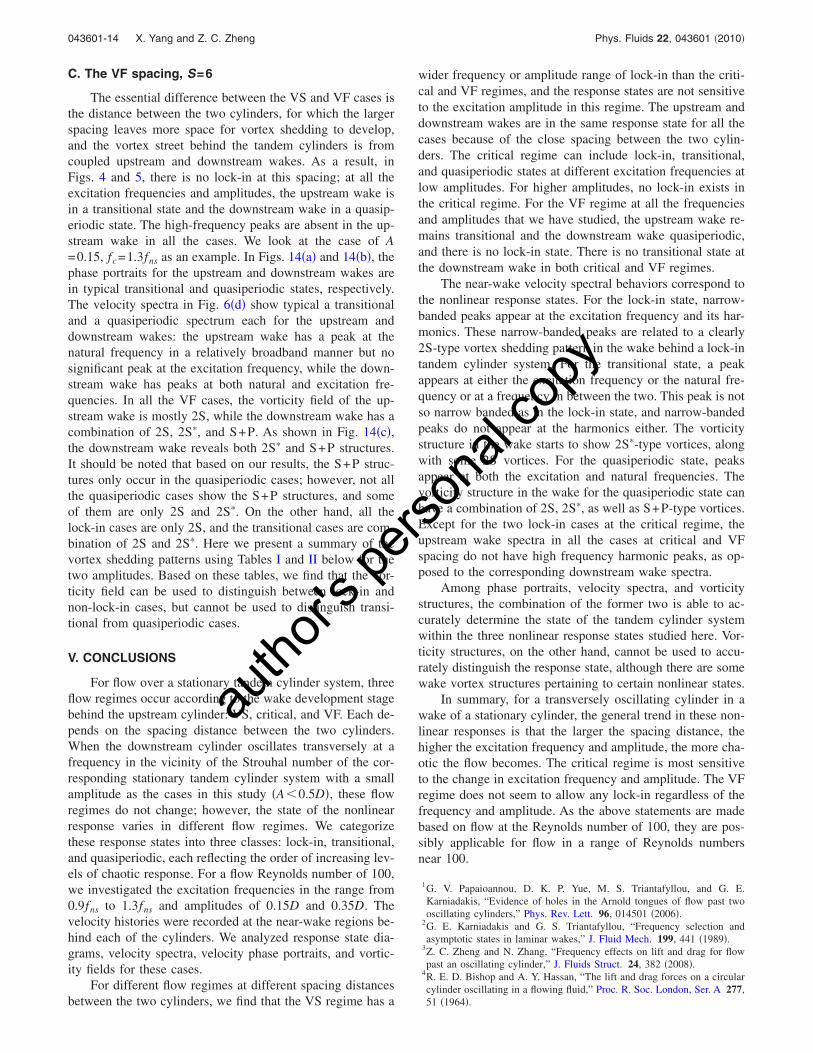
C. The VF spacing, S=6
The essential difference between the VS and VF cases isthe distance between the two cylinders, for which the largerspacing leaves more space for vortex shedding to develop,and the vortex street behind the tandem cylinders is fromcoupled upstream and downstream wakes. As a result, inFigs. 4 and 5, there is no lock-in at this spacing; at all theexcitation frequencies and amplitudes, the upstream wake isin a transitional state and the downstream wake in a quasip-eriodic state. The high-frequency peaks are absent in the up-stream wake in all the cases. We look at the case of A=0.15, fc=1.3fns as an example. In Figs. 14�a� and 14�b�, thephase portraits for the upstream and downstream wakes arein typical transitional and quasiperiodic states, respectively.The velocity spectra in Fig. 6�d� show typical a transitionaland a quasiperiodic spectrum each for the upstream anddownstream wakes: the upstream wake has a peak at thenatural frequency in a relatively broadband manner but nosignificant peak at the excitation frequency, while the down-stream wake has peaks at both natural and excitation fre-quencies. In all the VF cases, the vorticity field of the up-stream wake is mostly 2S, while the downstream wake has acombination of 2S, 2S�, and S+P. As shown in Fig. 14�c�,the downstream wake reveals both 2S� and S+P structures.It should be noted that based on our results, the S+P struc-tures only occur in the quasiperiodic cases; however, not allthe quasiperiodic cases show the S+P structures, and someof them are only 2S and 2S�. On the other hand, all thelock-in cases are only 2S, and the transitional cases are com-bination of 2S and 2S�. Here we present a summary of thevortex shedding patterns using Tables I and II below for thetwo amplitudes. Based on these tables, we find that the vor-ticity field can be used to distinguish between lock-in andnon-lock-in cases, but cannot be used to distinguish transi-tional from quasiperiodic cases.
V. CONCLUSIONS
For flow over a stationary tandem cylinder system, threeflow regimes occur according to the wake development stagebehind the upstream cylinder: VS, critical, and VF. Each de-pends on the spacing distance between the two cylinders.When the downstream cylinder oscillates transversely at afrequency in the vicinity of the Strouhal number of the cor-responding stationary tandem cylinder system with a smallamplitude as the cases in this study �A�0.5D�, these flowregimes do not change; however, the state of the nonlinearresponse varies in different flow regimes. We categorizethese response states into three classes: lock-in, transitional,and quasiperiodic, each reflecting the order of increasing lev-els of chaotic response. For a flow Reynolds number of 100,we investigated the excitation frequencies in the range from0.9fns to 1.3fns and amplitudes of 0.15D and 0.35D. Thevelocity histories were recorded at the near-wake regions be-hind each of the cylinders. We analyzed response state dia-grams, velocity spectra, velocity phase portraits, and vortic-ity fields for these cases.
For different flow regimes at different spacing distancesbetween the two cylinders, we find that the VS regime has a
wider frequency or amplitude range of lock-in than the criti-cal and VF regimes, and the response states are not sensitiveto the excitation amplitude in this regime. The upstream anddownstream wakes are in the same response state for all thecases because of the close spacing between the two cylin-ders. The critical regime can include lock-in, transitional,and quasiperiodic states at different excitation frequencies atlow amplitudes. For higher amplitudes, no lock-in exists inthe critical regime. For the VF regime at all the frequenciesand amplitudes that we have studied, the upstream wake re-mains transitional and the downstream wake quasiperiodic,and there is no lock-in state. There is no transitional state atthe downstream wake in both critical and VF regimes.
The near-wake velocity spectral behaviors correspond tothe nonlinear response states. For the lock-in state, narrow-banded peaks appear at the excitation frequency and its har-monics. These narrow-banded peaks are related to a clearly2S-type vortex shedding pattern in the wake behind a lock-intandem cylinder system. For the transitional state, a peakappears at either the excitation frequency or the natural fre-quency or at a frequency in between the two. This peak is notso narrow banded as in the lock-in state, and narrow-bandedpeaks do not appear at the harmonics either. The vorticitystructure in the wake starts to show 2S�-type vortices, alongwith some 2S vortices. For the quasiperiodic state, peaksappear at both the excitation and natural frequencies. Thevorticity structure in the wake for the quasiperiodic state canhave a combination of 2S, 2S�, as well as S+P-type vortices.Except for the two lock-in cases at the critical regime, theupstream wake spectra in all the cases at critical and VFspacing do not have high frequency harmonic peaks, as op-posed to the corresponding downstream wake spectra.
Among phase portraits, velocity spectra, and vorticitystructures, the combination of the former two is able to ac-curately determine the state of the tandem cylinder systemwithin the three nonlinear response states studied here. Vor-ticity structures, on the other hand, cannot be used to accu-rately distinguish the response state, although there are somewake vortex structures pertaining to certain nonlinear states.
In summary, for a transversely oscillating cylinder in awake of a stationary cylinder, the general trend in these non-linear responses is that the larger the spacing distance, thehigher the excitation frequency and amplitude, the more cha-otic the flow becomes. The critical regime is most sensitiveto the change in excitation frequency and amplitude. The VFregime does not seem to allow any lock-in regardless of thefrequency and amplitude. As the above statements are madebased on flow at the Reynolds number of 100, they are pos-sibly applicable for flow in a range of Reynolds numbersnear 100.
1G. V. Papaioannou, D. K. P. Yue, M. S. Triantafyllou, and G. E.Karniadakis, “Evidence of holes in the Arnold tongues of flow past twooscillating cylinders,” Phys. Rev. Lett. 96, 014501 �2006�.
2G. E. Karniadakis and G. S. Triantafyllou, “Frequency selection andasymptotic states in laminar wakes,” J. Fluid Mech. 199, 441 �1989�.
3Z. C. Zheng and N. Zhang, “Frequency effects on lift and drag for flowpast an oscillating cylinder,” J. Fluids Struct. 24, 382 �2008�.
4R. E. D. Bishop and A. Y. Hassan, “The lift and drag forces on a circularcylinder oscillating in a flowing fluid,” Proc. R. Soc. London, Ser. A 277,51 �1964�.
043601-14 X. Yang and Z. C. Zheng Phys. Fluids 22, 043601 �2010�
autho
r's pe
rsona
l cop
y

5C. H. K. Williamson and A. Roshko, “Vortex formation in the wake of anoscillating cylinder,” J. Fluids Struct. 2, 355 �1988�.
6S. Krishnamoorthy, S. J. Price, and M. P. Paidoussis, “Cross-flow past anoscillating circular cylinder: Synchronization phenomena in the nearwake,” J. Fluids Struct. 15, 955 �2001�.
7M. M. Zdravkovich, Flow Around Circular Cylinders �Oxford UniversityPress, New York, 1997�.
8P. Anagnostopoulos, “Numerical study of the flow past a cylinder excitedtransversely to the incident stream. Part 1: Lock-on zone, hydrodynamicforces and wake geometry,” J. Fluids Struct. 14, 819 �2000�.
9E. Guilmineau and P. Queutey, “A numerical simulation of vortex shed-ding from an oscillating circular cylinder,” J. Fluids Struct. 16, 773�2002�.
10M. M. Zdravkovich, “Flow-induced oscillations of two interfering circularcylinders,” J. Sound Vib. 101, 511 �1985�.
11Y. Tanida, A. Okajima, and Y. Watanabe, “Stability of a circular cylinderoscillating in uniform flow or in a wake,” J. Fluid Mech. 61, 769 �1973�.
12J. Li, A. Chambarel, M. Donneaud, and R. Martin, “Numerical study oflaminar flow past one and two circular cylinders,” Comput. Fluids 19, 155�1991�.
13B. Sharman, F. S. Lien, L. Davidson, and C. Norberg, “Numerical predic-tions of low Reynolds number flows over two tandem circular cylinders,”Int. J. Numer. Methods Fluids 47, 423 �2005�.
14J. Deng, A.-L. Ren, J.-F. Zou, and X.-M. Shao, “Three-dimensional flowaround two-circular cylinders in tandem arrangement,” Fluid Dyn. Res.38, 386 �2006�.
15G. V. Papaioannou, D. K. P. Yue, M. S. Triantafyllou, and G. E.Karniadakis, “Three-dimensionality effects in flow around two tandemcylinders,” J. Fluid Mech. 558, 387 �2006�.
16J. Li, J. Sun, and B. Roux, “Numerical study of an oscillating cylinder in
uniform flow and in the wake of an upstream cylinder,” J. Fluid Mech.237, 457 �1992�.
17N. Mahir and D. Rockwell, “Vortex formation from a forced system of twocylinders. 1. Tandem arrangement,” J. Fluids Struct. 10, 473 �1996�.
18A. Ongoren and D. Rockwell, “Flow structure from an oscillating cylinder.Part 1. Mechanisms of phase shift and recovery in the near wake,” J. FluidMech. 191, 197 �1988�.
19R. Govardhan and C. H. K. Williamson, “Modes of vortex formation andfrequency response of a freely vibrating cylinder,” J. Fluid Mech. 420, 85�2000�.
20R. Govardhan and C. H. K. Williamson, “Mean and fluctuating velocityfields in the wake of a freely-vibrating cylinder,” J. Fluids Struct. 15, 489�2001�.
21G. V. Papaioannou, D. K. P. Yue, M. S. Triantafyllou, and G. E.Karniadakis, “On the effect of spacing on the vortex-induced vibrations oftwo tandem cylinders,” J. Fluids Struct. 24, 833 �2008�.
22T. L. Morse and C. H. K. Williamson, “Employing controlled vibrations topredict fluid forces on a cylinder undergoing vortex-induced vibration,” J.Fluids Struct. 22, 877 �2006�.
23T. L. Morse and C. H. K. Williamson, “Fluid forcing, wake modes andtransitions for a cylinder undergoing controlled oscillations,” J. FluidsStruct. 25, 697 �2009�.
24N. Zhang and Z. C. Zheng, “An improved direct-forcing immersed-boundary method for finite difference applications,” J. Comput. Phys.221, 250 �2007�.
25C. H. K. Williamson, “Vortex dynamics in the cylinder wake,” Annu. Rev.Fluid Mech. 28, 477 �1996�.
26T. Leweke, M. Provansal, G. D. Miller, and C. H. K. Williamson, “For-mation in cylinder wakes at low Reynolds numbers,” Phys. Rev. Lett. 78,1259 �1997�.
043601-15 Nonlinear spacing and frequency effects Phys. Fluids 22, 043601 �2010�
autho
r's pe
rsona
l cop
y