
PERPUSTAKAAN No. Peroje:an No. algguan FR!A±PAHA
24
FABRICATION OF WIND TUNNEL: DIMENSIONAL ANALYSIS AND SIMILITUDE THEORY APPLICATIONS NORUL HUSNA BT. IBRAHIM A thesis submitted is fulfillment of the requirements for the award of the degree of Bachelor of Manufacturing Engineering Faculty of Manufacturing Engineering University Malaysia Pahang JUNE 2012 PERPUSTAKAAN No. Peroje:an No. algguan FR!A±PAHA rs
Transcript of PERPUSTAKAAN No. Peroje:an No. algguan FR!A±PAHA
FABRICATION OF WIND TUNNEL: DIMENSIONAL ANALYSIS AND SIMILITUDE THEORY APPLICATIONS
NORUL HUSNA BT. IBRAHIM
A thesis submitted is fulfillment of the requirements for the award of the degree of
Bachelor of Manufacturing Engineering
Faculty of Manufacturing Engineering
University Malaysia Pahang
JUNE 2012PERPUSTAKAAN
No. Peroje:an No. algguan FR!A±PAHA
rs
ABSTRACT
This fmal year project is about Fabrication of wind tunnel in desktop size. Wind tunnel Wind tunnel is a device used to investigate an interaction between solid body flows in wind tunnel can be performed in term of monitoring physical flow phenomenon such as laminar, turbulent and separation flows, vortex of shock wave. It's also able to measure aerodynamic quantities such as pressure, skin friction, lift, drag and moments. But this report will focus on the model to be test in wind tunnel. It's about applications of similitude theory on the prototypes. The main step is scale down the shape and dimension of the prototype or real model into the model. This similitude theory application will save money and space toward industries.
VII
ABSTRAK
Projek tahun akhir mi adalah tentang fabrikasi terowong angin bersaiz meja. Terowong angin adalah perantilalat yang digunakan untuk menyiasat interaksi aliran terhadap objek. mi boleh dilakukan untuk memantau fenomena aliran fizikal seperti laminar, aliran gelora and pemisahan, dan pusaran gelombang kejutan. la juga mampu untuk mengukur kuantiti aerodinamik seperti tekanan, geseran permukaan, daya seretan dan momen. Tetapi laporan mi akan memberi tumpuan kepada pembuatan model prototype untul di uji di dalam terowong angin. la An mengaplikasikn teori perbandingan model. Langkah utama ialah mengecilkan skala prototype kepada model. mi akan menjimatkn wang dan ruang.
VIII
TABLE OF CONTENTS
ix
CHAPTER TITLE
ACKNOWLEDGEMENT
ABSTRACT
ABSTRAK
TABLE OF CONTENTS
LIST OF TABLES
LIST OF FIGURES
LIST OF SYMBOLS
CHAPTER 1 INTRODUCTION
1.1 Background of Project
1.2 Problem Statement
1.3 Objective
CHAPTER 2 LITERATURE REVIEW
2.1 Overview
2.2 Wind Tunnel
2.2.1 Wind Tunnel Testing
2.3 Dimensional Analysis
PAGE
A
vii
viii
ix
xl'
xlii
xiv
1
1
7
7
5
8
8
8
9
2.3.1 The Method of Dimensional Analysis Using
Similitude Theory 9
2.3.2 Method of Dimensional Analysis 9
2.4 Model Scaling 12
2.5 Pitot Tube Usage 15
2.6 Scale Modeling 15
2.7 Dimensional Analysis And Similitude Theory 16
2.8 Similtude Relationship 17
CHAPTER 3 METHODOLOGY 18
3.1 Overview 18
3.2 Overall Methodology of the Project 19
3.2.1 Fabrication of Wind Tunnel 20
3.2.2 Fan Spesification 20
3.2.3 Application Dimensional Analysis and
Similitude on Model 21
3.2.4 Data Analysis 24
3.3 Material and Tool Used 25
3.3.1 CATIA software 25 3.3.2 Rapid Prototyping 25
3.4 Summary 26
x
XI
CHAPTER 4 RESULT AND DISCUSSION 27
4.1 Overview 27
4.2 Dimensional Analysis 27
4.3 Model From Prototype 29
4.3.1 Car model 29
4.3.2 Street Lamp model 31
4.3.3 Public Phone model 34
4.344 Vending Machine model 35
4.3.5 Soccer ball model 37
4.4 Model Fabrication 40
CHAPTER 5 CONCLUSION 42
5.1 Overview 42
5.2 Conclusion 42
REFERENCES 'U
LIST OF APPENDICES

LIST OF TABLES
Table No. Title Page
2.1 Similitude coefficient of models 17
3.1 Spesification of wind tunnel 20
4.1 Similitude result of Car model 31
4.2 Similitude result of Street lamp model 33
4.3 Similitude result of Public Phone 35
4.4 Similitude result of vending machine 37
4.5 Similitude result of Soccer ball 39
XII
LIST OF FIGURES
Figure No. Title Page
3.1 Flow Chart of the methodology 19
3.2 Rapid prototyping machine 22
4.1 Front view of prototype 29
4.2 Front view of model after scale 29
4.3 Side view of prototype 30
4.4 Side view of model after scale 30
4.5 Drawing of Street Lamp prototype 32
4.6 Drawing of Street Lamp Model 32
4.7 The prototype of public phone 34
4.8 The model design of public phone using CATIA software 34
4.9 Prototype drawing of vending machine 36
4.10 Model design of vending machine using CATIA software 36
4.11 The prototype of soccer ball 38
4.12Model of soccer ball design in CATIA software 38
4.13 Model of street lamp 40
4.14Model of public phone design using CATIA software. 40
4.15Model of vending machine 41
4.16Model of soccer ball 41
XIII
LIST OF SYMBOLS
Fluid viscosity
k Thermal Conductivity
Velocity of Object or Fluid
vs Velocity of Sound in Specified Medium
Pr Prandtl Number
Cp Specific heat at Constant Pressure
M Mach Number
Fr Froude Number
1 Characteristic Length
g Acceleration of Gravity
P Fluid density
Length scale
xiv
CHAPTER 1
INTRODUCTION
1.1 BACKGROUND OF PROJECT
1.1.1 Wind tunnel
A wind tunnel is a device used to producing a moving air stream for experimental
purposed. Stevenson (1969) stated that the main purpose of wind tunnel is to provide a
uniform and turbulence-free stream of air. Anderson (1989) stated that wind tunnel is
ground-base experimental facilities, design to produce flows of air that simulate natural
flows occurring outside the laboratory.
Apparently, low speed wind tunnels are one type of tools in the teaching of
aerodynamics or fluid mechanic. The basic test methods for large and small wind tunnel are
similar. The term low speed wind tunnels refer to wind speed with air speed less than 133
m/s or where the effect of compressibility can be neglected.
1.1.2 Modeling in various field
Model testing has been used with convincing success in many areas of the physical
and engineering sciences. The development of modern ships and airplanes would be
unthinkable without this tool. Another area of model testing covers the flow phenomena in
rivers and near the beach of the ocean. The magnetic signature of ships can be determined
by means of models. The strength of complicated structures and their tendency to undergo
dangerous vibrations is one of the examples where modeling has been made. For instance,
stresses and deflections were measured in a 1 240 model of the Hoover Dam. In the
experiment mercury was used to simulate the liquid loading. A most remarkable in the
2
history of model testing concerns the Tacoma Narrows Bridge, the third longest suspension
bridge at that time. Extensive dynamic model test were made to detect the absence of
dangerous wind-induced vibration. On 7 November 1940, four months after its opening, the
great structure met a tragic end.
1.1.3 Model testing classes
In the field of model testing, there distinguish three classes of model:
(A)Similar models. Such models are exact small scale reproduction of the full
scale prototype.
(B) Distorted models. An example is the model of a river which reproduce the
propagation of floods and similar phenomena. The height of the water above
the bottom is usually not reproduced in the same scale as the horizontal
dimension.
(C) Dissimilar models. This is a synonym of 'analogue', an electrical circuit which
simulates oscillations of a mechanical system. In this study, will not deal with
this type of model.
1.1.4 Scaling and Similitude
The meaning of the verb 'to scale' is to reduce in size according to a fixed ration.
The latter usage is clearly objectionable, because in reference to scientifically the term
scaling means more than to reduce the size. So, it is impiled that the model tests will
reproduce the full scale phenomena we want to study. In other words, we imply that there is
a similarity between the full scale tests and the model tests.
Scaling refers to the method by which the parameters of a model test are valid
representations of those occurring in the full scale, for example there is similitude. The
most important parameters of a modal test are the scale or scale factor of the various
magnitude5 for example length scale, pressure scale etc. Here, scale means the ratio of
Corresponding magnitudes of the model and prototype.
3
Aircraft and spacecraft comprise the class of aerospace structure that require
efficiency and wisdom in design, sophistication and accuracy in analysis and numerous and
careful experimental evaluations of components and prototype, in order to achieve the
necessary reliability, performance and safety.
Preliminary and concept design is accomplished through experience based on
previous similar designs, and through the possible use of models to stimulate the entire
system characteristics. [D. Durban et al. (eds.). Advances in the Mechanic of Plates and
Shells, 295-310. 2001 Kluwer Academic Publisher. Printed in the Netherlands.]
The last step in the design process is the verification of the design. This step
necessitates the production of large components and prototypes in order to test component
and system analytical predictions and verify strength and performance requirements under
the worst loading conditions that the system is expected to encounter in service.
Clearly then, full scale testing is in many cases necessary and always very
expensive. In the aircraft industry, in addition to full-scale tests, certification and safety
necessitate large component static and dynamic testing. The C 141 A ultimate static tests
include eight wing tests and seven empennage tests (McDougal, 1987). Such tests are
extremely difficult, time consuming and definitely absolutely necessary. It is hoped, to
reduce full-scale testing to a minimum.
Then, full scale large component testing is necessary in other industries as well.
Ship building, building construction, automobile and railway car construction all rely
heavily on testing.
Regardless of the application, a scale down (by a large factor) model (scale model)
which closely represent the structural behavior of the full-scale system (prototype) can
Prove to be an extremely beneficial tool. This possible development must be based on the
existence of certain structural parameters that can control the behavior of a structural
system when acted upon by static and dynamic loads. If such structural parameters exist, a
4
scaled-down replica can be built, which will duplicate the response of the full scale system.
The two systems are then said to be structurally similar. The term that best describes this
similarity is structural similitude.
1.1.5 Dimensional Analysis
Dimensional Analysis of the main fluid mechanics equations of the Navier-Stokes
Equation and the Energy Equation lead to four main dimensionless coefficients used to
maintain flow similarity - Froude number, Reynolds number, Mach number, and Prandtl
number (Barlow 9-15). The Prandtl number is usually neglected in wind tunnels because it
mainly deals with the temperature dependent aspect of a fluid, and is usually does not have
a significant contribution; see Equation 4-1 (Barlow 11). Mach number is used to represent
the proportion of an object of fluid's velocity to that of the speed of sound, See Equation 4-
2. In air at 150C and sea level the speed of sound is 340.3 m/s, 761.2 mph, 1,225 km/h
(Clancy 7).
To be classified as a "lowspeed" wind tunnel it is generally accepted that the Mach
number must be below 0.3, making the Mach number also not a significant flow similarity
parameter. The Froude number is an important flow similarity for systems where the
dynamic interactions between the model and fluid cause unsteady boundary conditions
because it takes into account the characteristic wave propagation velocity, see Equation 4-3
(Barlow 10). Since the main purpose of this project is creating an ABL wind tunnel for
low-rise structure testing where there will be limited model flexure the Froude number is
not usually used for flow similarity.
However, to be versatile the wind tunnel will also be able to create stable flows
even at very low velocities for Froude number similitude for testing high rise buildings. In general, for applications where the geometry is fixed and the dynamic interactions are
neglected such as ABL wind tunnels for testing low rise structures the most significant fluid
flow similarity parameter is the Reynolds number (Barlow 11). The Reynolds number is
based on the fluid density, viscosity, velocity, and the model's characteristic length. The
Reynolds number maintains the ratio of the inertia force to the viscous force between the
full size structure and the model.
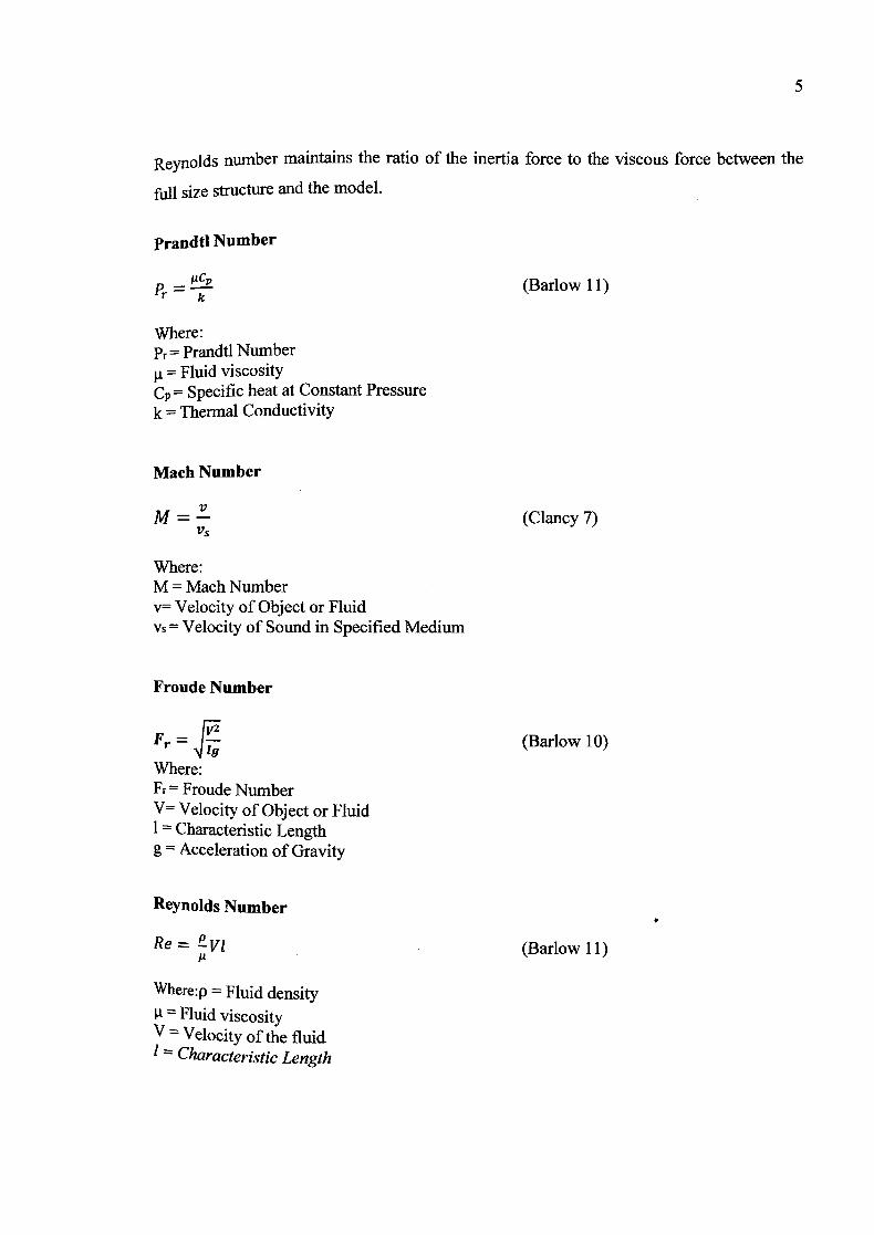
Prandtl Number
- ,2cp
P- (Barlow 11)
Where: Pr = Prandtl Number p. = Fluid viscosity Cp = Specific heat at Constant Pressure k = Thermal Conductivity
Mach Number
M = (Clancy 7) VS
Where: M = Mach Number v= Velocity of Object or Fluid Vs = Velocity of Sound in Specified Medium
Froude Number
Fr = 4 1g (Barlow 10)
Where: Fr Froude Number V= Velocity of Object or Fluid I Characteristic Length g = Acceleration of Gravity
Reynolds Number
Re= Evl (Barlow 11) IL
Where:p Fluid density W= Fluid viscosity V Velocity of the fluid 1 Characteristic Length
1.16 Buckingham's P1 Theorem
The notion of similitude first entered into the field of engineering mechanics
probably by Euler and then it is extended into the field of heat transfer in the early 1800s by
Fourier. It is not until fifty years afterwards that a generalized framework of the study of
similitude was developed by Lord Rayleigh and named as "The Method of Dimensions".
Shortly after that, Carvallo and Vaschy independently formulated the method of dimensions
as a formal mathematical theorem. The theorem was believed to be forgotten until
Buckingham wrote a series of papers on the subject starting in 1914 which made this
theorem significantly more well-known to the scientific community. This explains why the
theorem is nowadays recognized as "Buckingham's Pi Theorem".
Buckingham's Pi Theoremi states that for every system completely described by N
variables and parameters in M fundamental dimensions, there exist N-M independent
dimensionless "Pi" parameters that must be kept invariant during scaling in order to
maintain dynamic similitude [9, 12]. In other words, Buckingham's Pi Theorem provides a
systematic method for determining the minimum set of dimensionless Pi parameters which
characterize the dynamics of a system. The selection of these Pi parameters is not unique,
but keeping them constant guarantees that all other dimensionless combinations of the
original N system variables and parameters will also remain constant. This type of analysis
is often referred to as Dimensional Analysis.
1.2 PROBLEM STATEMENT
In aerospace field, airplanes need to be test before it being launched and being used
in public. Commonly the testing will be held in wind tunnel. But, if we see the airplane, it is
big in size which is 27 meter (m). So, if the aerospace engineers want to test the 27m length
aeroplane, they need to build at least 30 m length of test section. It is too big. So, the
expertise decided to build small size of the airplane by scale it down. Although, the size is
scaled down, the dimension and air flow over the prototype have to similar. This situations
is similar to the automotive industries. They need to test their prototype, if there are
unperfect part or error on design they need to do the prototype again. If the applied the
similitude theory, the only need to fabricate the small size model. They can make the model
in many type of design. It will reduce the use of money and space absolutely.
1.2 OBJECTIVE OF PROJECT
The main purpose of this project is to study the application of similitude theory
under dimensional analysis section. Besides that, this project will give the knowledge on
wind tunnel fabrication including the component involved.
7
CHAPTER 2
LITERATURE REVIEW
2.1 OVERVIEW
The purpose of this chapter is to provide a review of past research efforts related to
dimensional analysis and similitude. It is also include the important component in modeling
the prototype and scale ratio. From the related journal and article, the idea in model's
similitude and designing the model is developed before going further to the next chapter in
completing this project.
2.2 WIND TUNNEL
2.2.1 Wind tunnel testing
Scale models are less expensive than full scale flight vehicles and by changing the
wind tunnel speed or pressure, Reynolds number can be matched. This is often difficult and
there are severe limitations, especially when one considers modeling flows associated with
atmospheric entry or hypersonic flight. However, the cost and advantages of working with
ground-based instrumentation makes this technique a staple of applied aerodynamics
Investigation. A simple wind tunnel configuration consists of an pen circuit with a
Contraction acting to increase airspeed, a test section in which experiments are conducted,
and a diffuser section.
2.3 DIMENSIONAL ANALYSIS
2.3.1 The Method of Dimensional Analysis Using Similitude Theory
The dimensional analysis and similitude theory were used for fluid flow modeling.
The dimensional analysis is a tool for studying the relationships that describe the physical
processes. Dimensional analysis is based on the fact that empirical or rational relations
must be dimensionally homogeneous, that means that all terms of a relation need to have
the same unit measures. The similitude theory is linking the theoretical aspect of a process
with experimental results related to this, creating the physical similitude between model
and prototype. The general conditions in studying the similar processes are elaborated. The
theory permits the using in practice of theoretical relationships as few dimensionless
formulas or to simplify the experimental study of the process by reducing the number of
studied describing variables.
2.3.2 Method Of-Dimensional Analysis
The strict similitude during a model test it is not always possible to realize, and in
several cases some aspects of similitude may be neglected, focusing only the most
important parameters. In this case, the length scale is kept independent. As base quantities
for the dimensional system is selected the length L, mass M, time T. For both scale model
and original, the values of the dimensionless parameters have to be the same because they
have to ensure the similitude, as follow:
UL = - (2.1) 'p
where, 0L - length scale, 'm - length of model, l,, - length of original.
10
For example, if the model and prototype (original) are using the same, then, the
density (p) expressed in dimensional system as ML-3, and dynamic viscosity (z)=ML-lT-1
are constants, the following relationship could be written:
ap = M L = 1 = a,, (2.2)
Where, cr - density scale, am - masses scale
UL 3. OIL-1. = 1 1 r. aT2 (2.3)
Where, 6T - times scale
The next step is to establish the determinative regime of process. For the
hydrodynamic processes the viscosity is determinative and the modeling is made based on
the similitude condition between model and prototype (original) that involve the Reynolds
numbers equality:
Rem = Re (2.4)
(pvd\ (pvd\ = .p (2.5)
Where dm, d - inner diameter of the pipe for original and model; Vm, VP - average velocity
of the fluid flow for original and model; Pm, . - fluid density for original and model; /Am,
pp - dynamic viscosity for original and model.
A 2 - Pm 0W
clAP - - CFL.2Tp (2.10)
11
There are noted the scaling ration with:
dm 1m(2.6)
Pm - tip (2.7) Pp
jtm tilL =( 2.8)
Yp
CFV
Vm =(2.9)
VP
The quantity o, will allow computing the original prototype velocity VP knowing
the model velocity Vm. Based on this value the fluid rate and pressure drop could be
calculated.
If the model and original are using the same fluid, then ci, = 1 and = 1. The modeling
equations become:
1
UL (2.11)
clAP = TL7(2.12)
It is marking out that the velocity scale ratio o, is in inverse proportion to length Scale ratio tiL. The effect is pronounced by maintaining the same volumetric flux rate while
Scaling down. Particularly, the pressure drop scale become huge in mini microchannels
Cross section, for the same fluid this enhance as CIL.2.
12
Based on result experiment presentations, it could be seen that for the values of
Reynolds number less than 2320, the friction coefficient values determined experimentally
for all pipes are consistent with the values calculated with the equation f = 64/Re. For
values of Reynolds number> 4000, experimentally determined values for the friction
coefficients have values consistent with the values calculated with the Prandtl - Karman
relations.
2.4 MODEL SCALING
Daigliesh (1975), Daigliesh (1982) and Daigliesh et al. (1983) compared
measurements of wind pressure at full-scale and on a 1/200 aeroelastic wind tunnel model
of the Commerce Court West Tower in Toronto. The 57-story steel frame (36.5 in x 69.7 in
x 239 m) was the tallest building in Canada when it was completed in 1973. Agreement
between model and full-scale measurements of mean pressures is satisfactory, but there are
important differences between the two sets of measurements of changeable pressures
caused by vortex shedding. The model, with mass lumped at seven levels, agreed
reasonably well with full scale measurements at the low and high end of the acceleration
spectrum, but underestimated the response in the intermediate frequency range.
Pattie and Milne (1966) used a 1:10 scale model of a poultry house to visualize air-
flow patterns and to measure air velocities for different air inlet configurations. They demonstrated that at Reynolds numbers of 0.20, 0.65 and 0.91 times that of the prototype,
there were no significant differences in either the airflow patterns or velocity distributions.
The same observation was made by Timmons (1984) who established a threshold Reynolds
number for a slot ventilated airspace under isothermal conditions.
13
2.5 pIlOT TUBE USAGE.
A Pitot tube is a tube whose open end is parallel to the flow direction and whose
other end is connected to a pressure-measuring device such as a manometer. A Pitot tube is
usually bent at 900 to protrude into an airstream or duct from within housing or outside the
duct. A Pitot-static tube, consists of two concentric tubes, one of which measures the
stagnation (total) pressure from the sensing tip, and the other of which measures the static
pressure of the moving fluid through static pressure taps (holes exposed perpendicular to
the flow) behind the sensing end. A Pitot tube is generally more useful since the difference
between total and static pressure, velocity head, can be measured with one instrument. So it
save money and energy. [R. Klopfenstein Jr., "Air Velocity and Flow Measurement Using a
Pitot Tube," ISA Transactions,.vol. 37, Sep. 1998, pp. 25 7-263.].
2.6 SCALE MODELING
Scale modeling has proven that it is useful in numerous fields of engineering, and
design to make predictions about a structure or system. Architects use scale models to
design buildings. Similarly, wind tunnels are used extensively to study the performance of
automobiles and all manner of aircraft and spacecraft. Hydrology, geophysics and
meteorology are also fields which have benefitted greatly from the application of scale
models. Nearly every engineering be in charge of concerned with physical systems has
made extensive use of scale models for studying very large or very small structures or
systems (D.F. Young,2007) (D.J. Schuring,1977).
Scale models are experimental models of structured that mirror the true physical
behavior of an original phenomenon, or a prototype. The system represented by the model
is called the prototype. The model is usually much smaller than the rrototype so as to be
easier to handle, be more easily accessible or controllable, cost less to build and operate,
use fewer materials, and/or be generally simpler to understand (D.J. Schuring,l977).
14
The object represented by the model is called the prototype. Usually, the model is
much smaller than the prototype so as to be easier to handle, be more easily accessible or
controllable. Otherwise, the costing in build and Operate is less because it use fewer
materials, and be generally simpler to understand by beginner and intermediate person
involve. (D.F. Young,2007)
Bunt Kittirungsi (2008), Doctor of Philosophy (Mechanical Engineering) in The
University of Michigan write, modeling and simulation techniques have widely become
instrumental in the design and development stage of many advanced technology programs.
They play an essential part in allowing a variety of design concepts to be generated and
tested without having to rely on physical prototypes. Therefore, they help companies
maintain their competitiveness by expediting the design and redesign processes of their
engineered products to efficiently keep up with the frequently changing, and stringent
needs in the market [Otto, K.N. and K.L. Wood, Product Evolution: A Reverse Engineering
and Redesign Methodology. Research in Engineering Design, 1998. 10(4): p. 226-243.]
In the initial design process, engineers often make use of modeling and simulation
techniques along with their hands-on experience to evolve their product into its optimum,
subject to possibly many specifications. Some of these specifications certainly have to be
later modified according to such stringent market needs. While these modifications render
the optimal original design no longer optimal for the new application, some desirable
properties of the original design may still have to be sustained and then migrated to the new
design. For instance, a vehicle powertrain engineer might wish to redesign an existing
automatic transmission optimized for one engine to use in conjunction with a more
Powerful engine. [Fathy, H.K., R. Ahiawat, and J.L. Stein. Proper powertrain modeling for
engine in- the-loop simulation. in 2005 ASME International Mechanical Engineering
Congress and Exposition, IMECE 2005, Nov 5-112005. 2005. Orlando, FL, United States: American Society of Mechanical Engineers, New York, NY 10016-5990, United States.]
15
• Geometric similarity
Many different similarity principles exist, each of which can be interpreted as a
metric quantifSii1g whether or not two systems are similar. First, geometric similarity
(Szirtes, T.1998), defines the conditions under which two objects are similar in shape and
dimension. This said that in geometric similarity, the shape and dimension of the model and
prototype is similar.
Kinematic similarity and dynamic similarity
Further, kinematic and dynamic similarities [Murphy, 0., Similitude in Engineering.
1950: The Ronald Press Company.] define the conditions under which the two objects
undergo an experience similar forces during motions, respectively. In particular, these
similarity conditions select the values at which the properties (e.g., length, density,
pressure, etc.) associated with one object has to be with respect to the other object. This
concept of dynamic similarity or dynamic similitude is applicable to any system in any
domain of mechanical, or thermofluid because the notions of force and motion are
equivalent to those of the power variables (i.e. flow) in system dynamics