Permissible level of voltage fluctuations for a motor
3
Guide for electrical design engineers Krzysztof Piatek AGH-University of Science & Technology Power Quality Power Quality Voltage drop calculation: permissible level of voltage fluctuations for a motor Supply system PPC 400 V M line L1 Tr line Lz 400 V Z PPC Z L Z r U PPC U N
-
Upload
hans-de-keulenaer -
Category
Documents
-
view
1.713 -
download
3
description
In this guide, a design engineer has to advise his industrial customer who plans to connect a new induction motor to the power supply system. Using the permissible level of voltage fluctuations, his methodology is described.
Transcript of Permissible level of voltage fluctuations for a motor
Guide for electrical design engineers
Krzysztof PiatekAGH-University of Science & Technology
Po
wer Q
uality
Power Quality
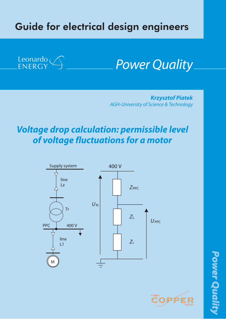
Voltage drop calculation: permissible level of voltage fluctuations for a motor
Supply system
PPC 400 V
M
lineL1
Tr
lineLz
400 V
ZPPC
ZL
Zr
UPPC
UN
2
http://www.leonardo-energy.org
Power Quality
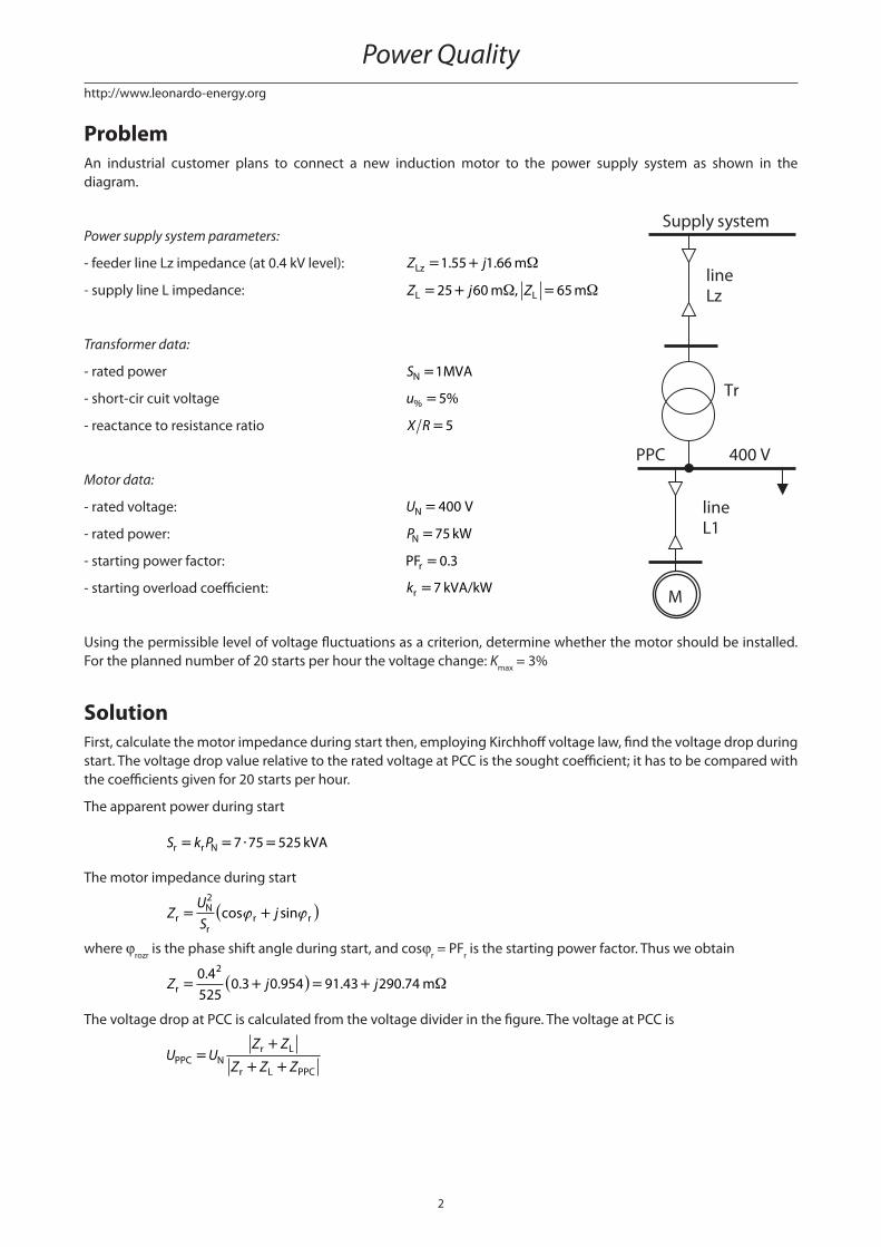
ProblemAn industrial customer plans to connect a new induction motor to the power supply system as shown in the diagram.
Power supply system parameters:
- feeder line Lz impedance (at 0.4 kV level): Z jLz m= +1 55 1 66. . Ω
- supply line L impedance: Z j ZL Lm m= + =25 60 65Ω Ω,
Transformer data:
- rated power SN MVA=1
- short-cir cuit voltage u% =5%
- reactance to resistance ratio X R =5
Motor data:
- rated voltage: UN V= 400
- rated power: PN kW=75
- starting power factor: PFr =0 3.
- starting overload coeffi cient: kr kVA/kW=7
Using the permissible level of voltage fl uctuations as a criterion, determine whether the motor should be installed. For the planned number of 20 starts per hour the voltage change: Kmax = 3%
SolutionFirst, calculate the motor impedance during start then, employing Kirchhoff voltage law, fi nd the voltage drop during start. The voltage drop value relative to the rated voltage at PCC is the sought coeffi cient; it has to be compared with the coeffi cients given for 20 starts per hour.
The apparent power during start
S k Pr r N kVA= = ⋅ =7 75 525
The motor impedance during start
ZUS
jrN2
rr r= +( )cos sinϕ ϕ
where ϕrozr is the phase shift angle during start, and cosϕr = PFr is the starting power factor. Thus we obtain
Z j jr m= +( )= +0 4525
0 3 0 954 91 43 290 742.
. . . . Ω
The voltage drop at PCC is calculated from the voltage divider in the fi gure. The voltage at PCC is
U UZ Z
Z Z ZPPC Nr L
r L PPC=
+
+ +
Supply system
PPC 400 V
M
lineL1
Tr
lineLz

3
http://www.leonardo-energy.org
Voltage drop calculation: permissible level of voltage fl uctuations for a motor
i.e. the relative voltage drop is
kUU
Z
Z ZuPPC
N PPC= =
+Σ
Σ
where Z Z Z jΣ Ω= + = +r L m116 43 350 74. .
The power system impedance at PCC equals the sum of the feeder line Lz and the transformer Tr impedances
Z Z ZPPC Tr Lz= +
The transformer impedance
Z Z jTr Tr Tr Tr= +( )cos sinϕ ϕ
where
Zu U
STrN
Nm= = ⋅ =% .
.100
0 050 4
18
2 2
Ω
whereas the angle ϕTr can be determined from the X/R ratio
tan , .ϕ ϕTr Tr= = =XR
5 78 69�
Inserting the calculated values to the transformer impedance formula, we obtain
Z j jTr m= +( )= +8 0 196 0 98 1 57 7 84. . . . Ω
Summing up with the feeder line Lz impedance, we obtain
Z jPPC m= +3 12 9 5. . Ω
Inserting the calculated impedances to the voltage divider formula, we obtain
kjj
ku u=+
+= = =
116 43 350 74119 55 360 24
369 56379 56
0 9736 97. .. .
.
.. , .336%
The relative voltage change coeffi cient is defi ned as
KUUu
PPC
N=
Δ
where ΔUPPC is the voltage drop at PCC during starting. It can be determined directly as
ΔU U k UPPC N u N V= − = −( )=400 1 0 9736 10 56. .
and, fi nally:
K Ku u= = =10 56400
0 026 2 6.
. , . %
Since this coeffi cient does not exceed the limit value of 3% the motor can be directly connected to the network.
This publication is subject to copyright and a disclaimer. Please refer to the Leonardo ENERGY website.
400 V
ZPPC
ZL
Zr
UPPC
UN