PERMEABILITY OF PEAT: an engineering case study Hanrahan Memorial Symposium University College...
29
ET Hanrahan Memorial Symposium University College Dublin, Belfield, Dublin 4, Ireland University College Dublin, Belfield, Dublin 4, Ireland 11 th September 2013 PERMEABILITY OF PEAT: an engineering case study Dr Paul Jennings and Turlough Johnston Applied Ground Engineering Consultants (AGEC) Ltd., Bagenalstown County Carlow Bagenalstown, County Carlow
-
Upload
vuongthuan -
Category
Documents
-
view
216 -
download
0
Transcript of PERMEABILITY OF PEAT: an engineering case study Hanrahan Memorial Symposium University College...

ET Hanrahan Memorial Symposium University College Dublin, Belfield, Dublin 4, IrelandUniversity College Dublin, Belfield, Dublin 4, Ireland
11th September 2013
PERMEABILITY OF PEAT:
an engineering case study
Dr Paul Jennings and Turlough Johnston
Applied Ground Engineering Consultants (AGEC) Ltd.,Bagenalstown County CarlowBagenalstown, County Carlow

Contents
• Introduction ‐ Peat in Engineering Works
‐ Examples of peat failures
• Case Study – Corrib Gas Onshore Pipeline
‐ Proposed construction – stone road
‐ Peat Conditions
‐ Typical Peat Engineering Properties
‐ Peat Permeabilityy
‐ Literature review
‐ Direct measurement ‐ laboratory testing
Direct measurement insitu testing‐ Direct measurement ‐ insitu testing
‐ Permeability Results and Analytical modelling
‐ Construction and mitigation measures
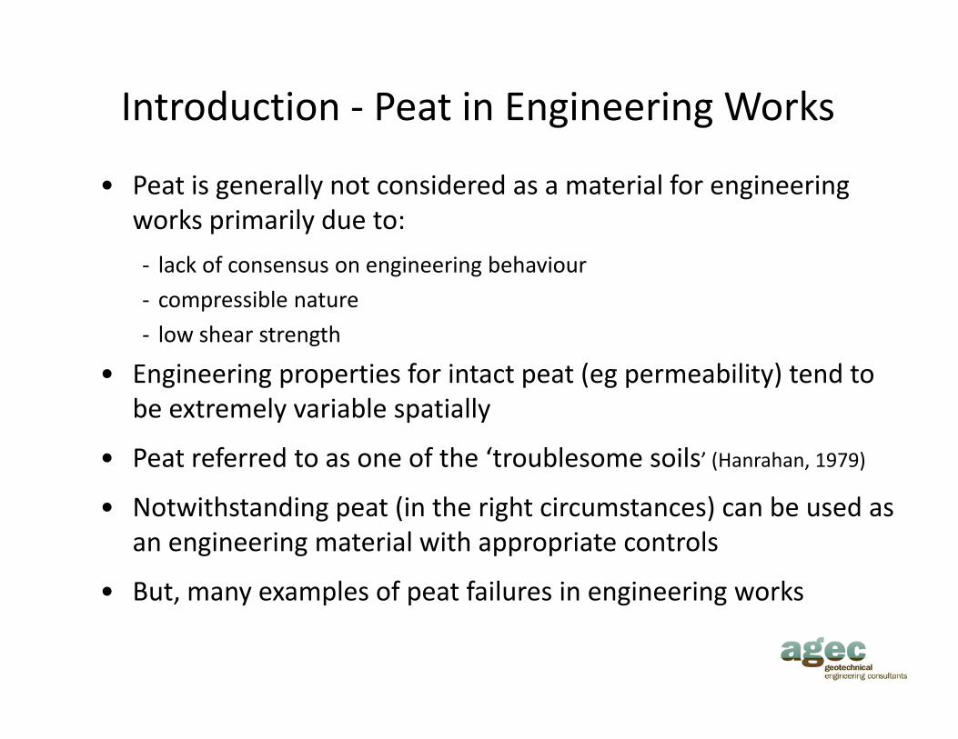
Introduction ‐ Peat in Engineering Works
• Peat is generally not considered as a material for engineering works primarily due to:p y
‐ lack of consensus on engineering behaviour
‐ compressible nature
‐ low shear strength
• Engineering properties for intact peat (eg permeability) tend to be extremely variable spatiallybe extremely variable spatially
• Peat referred to as one of the ‘troublesome soils’ (Hanrahan, 1979)
• Notwithstanding peat (in the right circumstances) can be used as• Notwithstanding peat (in the right circumstances) can be used as an engineering material with appropriate controls
• But, many examples of peat failures in engineering works, y p p g g

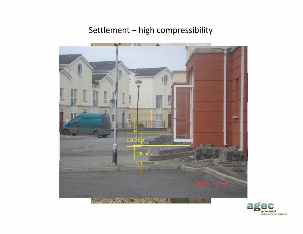
Settlement – high compressibility
200c.200mm
Settlement – high compressibility
c.300mm
c.400mm
c.600mm
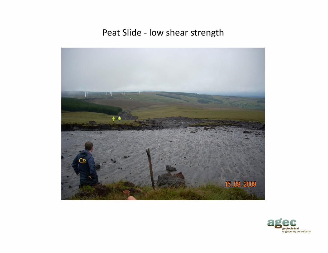
Peat Slide ‐ low shear strength

Bigger Peat Slide ‐ low shear strength
c.50m
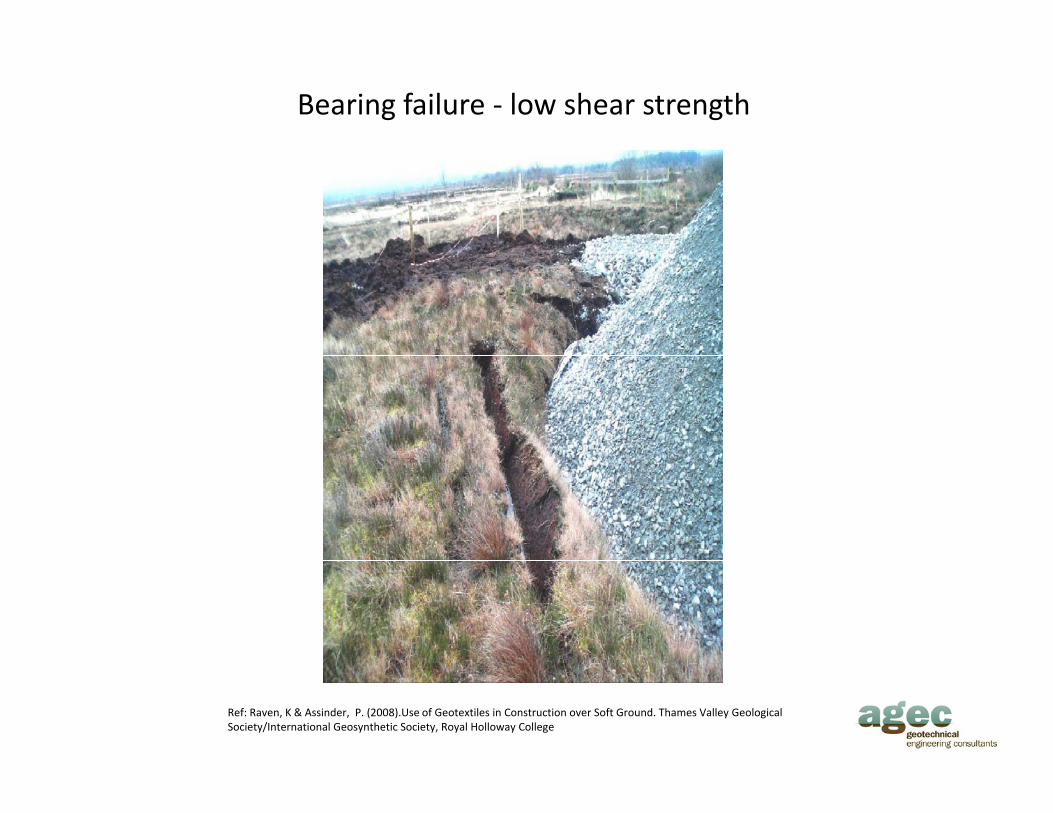
Bearing failure ‐ low shear strength
Ref: Raven, K & Assinder, P. (2008).Use of Geotextiles in Construction over Soft Ground. Thames Valley Geological Society/International Geosynthetic Society, Royal Holloway College

Case Study – Corrib Gas Onshore Pipeline
• Corrib gas pipeline located in County Mayo (NW Ireland):
‐ 84km offshore
‐ 8.3km ‘onshore’, including
‐ 4.7km estuary/bay tunnel
‐ 3 6km mostly within peatland (Atlantic blanket bog)3.6km mostly within peatland (Atlantic blanket bog)
• Peatland habitat in/adjacent to works protected under EU Habitats Directive
• Construction in peatland using stone road (to avoid instability issues)
• Concern that in peatland areas vertical & lateral groundwater leakage as a result of works would damage protected habitats
• Construction methodology developed using reworked peat to d i d h biprotect designated habitats
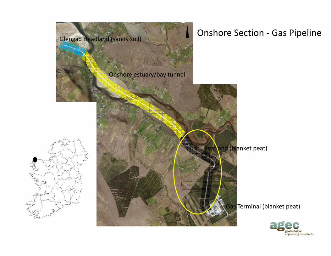
Glengad Headland (sandy soil)Onshore Section ‐ Gas Pipeline
Onshore estuary/bay tunnel
Peatland (blanket peat)
Gas Terminal (blanket peat)( p )
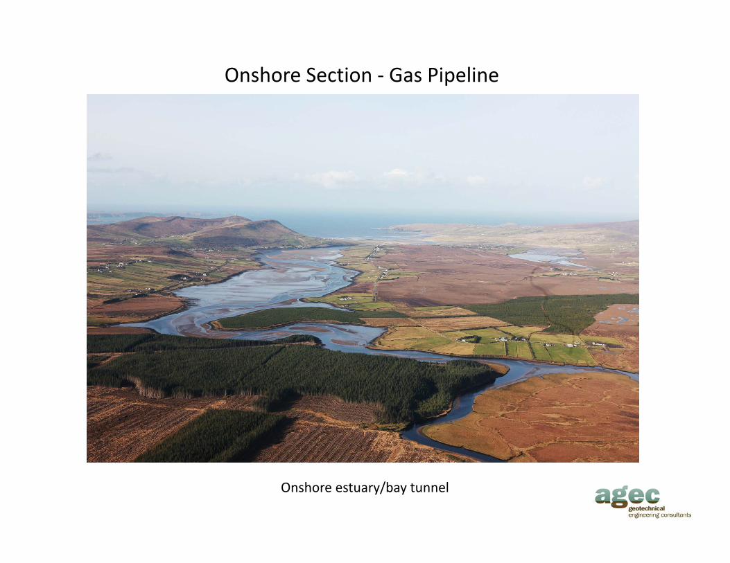
Onshore Section ‐ Gas Pipeline
Onshore estuary/bay tunnel
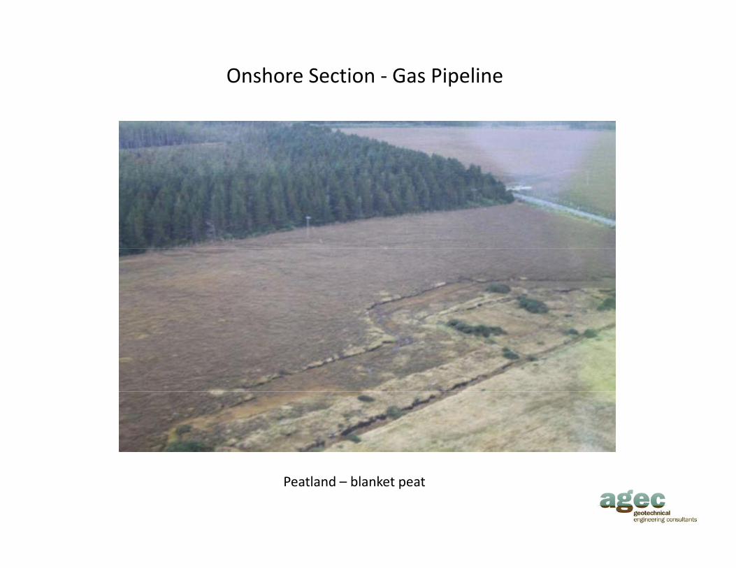
Onshore Section ‐ Gas Pipeline
Peatland – blanket peat
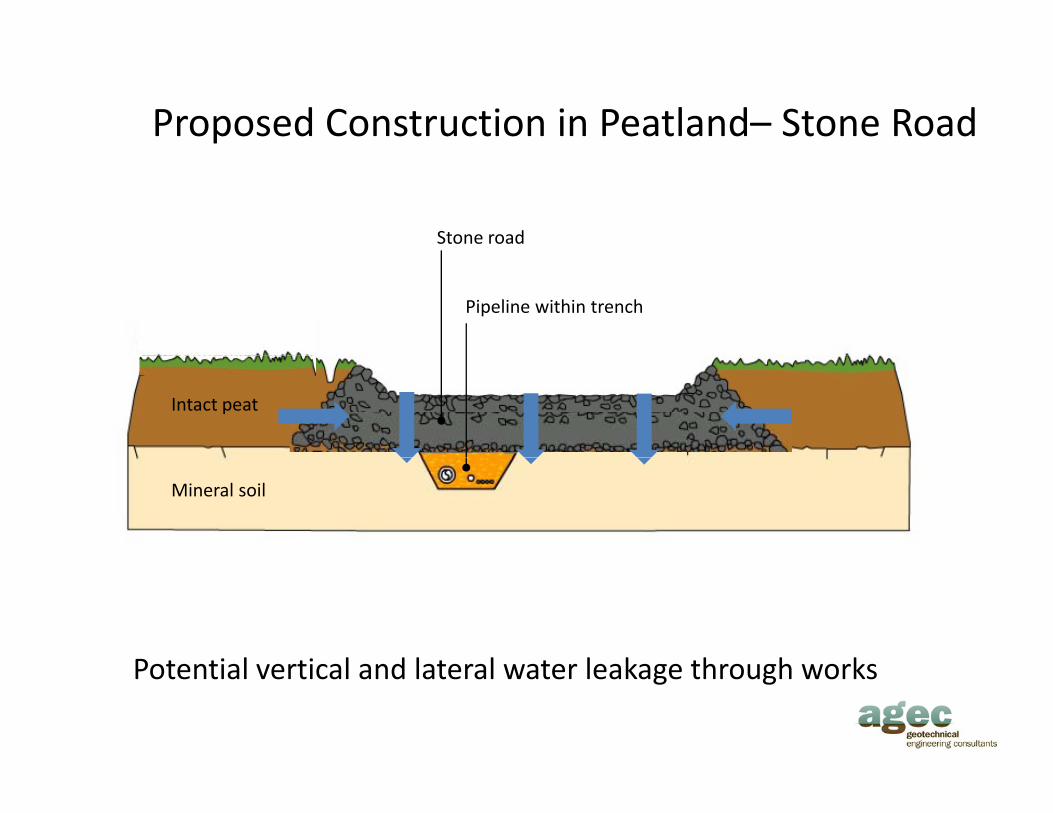
Proposed Construction in Peatland– Stone Road
Stone road
Pipeline within trench
Intact peat
Mineral soil
P t ti l ti l d l t l t l k th h kPotential vertical and lateral water leakage through works

General Peat Conditions• General
‐ Onshore route within forested and open peatland
‐ Peat thickness typically 3m with locally up to about 5mPeat thickness typically 3m with locally up to about 5m
‐ Peat organic content (>90%) with 2 distinct layers within vertical peat profile, namely
• Uppermost peat layer (acrotelm) contains actively growing plants• Uppermost peat layer (acrotelm) contains actively growing plants‐ Typically 0.3m to 0.7m thick
‐ Relatively strong
‐ Permeability: say 10‐1 to 10‐6 m/s
• Lower peat layer (catotelm) contains decaying plant matterMany metres deep‐ Many metres deep
‐ Plant matter in different degrees of humification
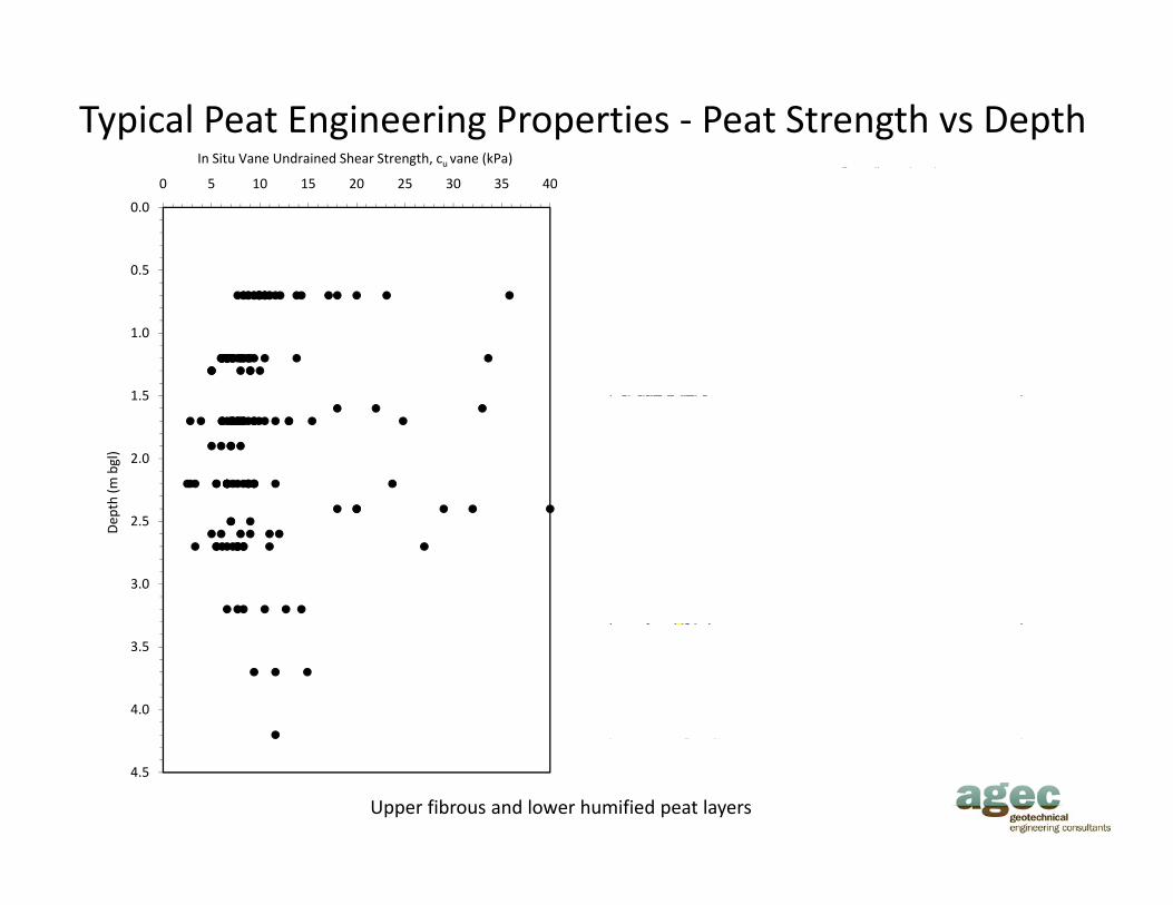
‐ Minimal strength (typically cu 2 to 15kPa)
‐ Permeability: say 10‐6 to less than10‐10 m/s
In Situ Vane Undrained Shear Strength, cu vane (kPa) CPT Undrained Shear Strength, cu CPT (kPa)
Typical Peat Engineering Properties ‐ Peat Strength vs Depth
0.0
0.5
0 5 10 15 20 25 30 35 40 0 5 10 15 20 25 30 35 40g u ( )
1.0
1 51.5
2.0
th (m
bgl)
2.5
3.0
Dep
3.5
4.0
4.5
Upper fibrous and lower humified peat layers

Typical Peat Engineering Properties ‐ General
0.0
0 500 1000 1500 2000 2500
Moisture Content (%)
0.60 0.80 1.00 1.20 1.40
Bulk Density (Mg/m3)
85 90 95 100
Organic Content (%)
0.0
0 1 2 3 4 5 6 7 8 9 10
von Post Humification (Hn)
100
0.5
1.0
1 5
0.5
1.0
1 5
0
50
100
1.5
2.0
2.5
Dep
th (m
bgl)
1.5
2.0
2.5
Dep
th (m
bgl)
0
50
50
100
3.0
3.5
D
3.0
3.5
0
50
50
100
4.0
4.5
4.0
4.5
0
Variation of moisture content, bulk density, organic content and von Post humification with depth for a Low‐level Blanket Bog

Peat Permeability ‐ Determination• Require mitigation to protect designated habitats using principally
(reworked) peat to maintain the hydrological balance in peatland
• Reworked peat included in works as hydraulic impedance layers
• Determination of peat permeability by:
‐ Literature review
‐ Direct measurement of peat permeability (laboratory & insitu)
Direct measurement of mineral soil permeability‐ Direct measurement of mineral soil permeability
‐ Direct measurement at existing sites containing reworked peat
• Analytical seepage modelling used to determine extent/type of reworked peat impedance layers

Literature Review ‐ Findings
• Typical insitu permeability from 10‐5 to 10‐7 m/s for fibrous peat decreasing to 10‐7 to 10‐12 m/s for more humified peat
• Significant decline in permeability with reduction in void ratio as a result of loading
• Decrease in permeability with reworking. Reworked peat with pre‐loading giving permeability in the range of 10‐8 to 10‐11 m/s (Dillon et al, 2004)
Peat Description Permeabilit (m/s) So rcePeat Description Permeability (m/s) SourcePeat 10‐6 Coley (1950)Fibrous Peat 4 x 10‐6 Hanrahan (1954)Amorphous and Fibrous Peat 10‐6 to 10‐7 Lee and Brawner (1963)Canadian Muskeg 10‐5 Adams (1965)Amorphous Peat 3 x 10‐8 to 10‐7 Galvin and Hanrahan (1967)Amorphous Peat 3 x 10 to 10 Galvin and Hanrahan (1967)Peat 10‐5 Weber (1969)Amorphous Peat 4 x 10‐7 Berry and Poskitt (1972)Fibrous Peat 8 x 10‐7 Berry and Poskitt (1972)Fibrous Peat 10‐5 to 10‐6 Berry and Vickers (1975)Amorphous to fibrous peat 10‐6 Dhowian and Edil (1980)p p ( )Fibrous Peat 10‐1 Ivanov (1981)Fibrous Peat 3 x 10‐7 Füstenberg et al (1983)Fibrous Peat 10‐5 to 10‐10 Lefebvre et al (1984)Blanket Peat 5.78x10‐8 to 1.7x10‐7 Mulqueen (1986)Sphagnum Peat 1.15x10‐7 to 2.3x10‐7 Mulqueen (1986)Peat 10‐5 ‐ 10‐7 Carlsten (1991)Fibrous Peat 6 x 10‐7 to 6 x 10‐8 Mesri et al (1997)

Literature Review ‐ Peat Permeability vs Humification
1.00E‐04
1.00E‐03 Sphagnum Peat ‐Hobbs (1986)
Sedge & Brushwood Peat ‐ Hobbs (1986)
Sphagnum Cotton Sedge & Heather Peat Hobbs (1986)
1.00E‐06
1.00E‐05
Sphagnum, Cotton Sedge & Heather Peat ‐ Hobbs (1986)
Fibric Peat ‐ Ryden (1990) in Magnussen (1994)
Hemic Peat ‐ Ryden (1990)
1.00E‐08
1.00E‐07
Perm
eability (m
/s) Sapric Peat ‐ Ryden (1990)
1.00E‐10
1.00E‐09
1.00E‐12
1.00E‐11
0 1 2 3 4 5 6 7 8 9 10
Humification, von Post (Hn)
Relationship between humification and permeability for different types of peat
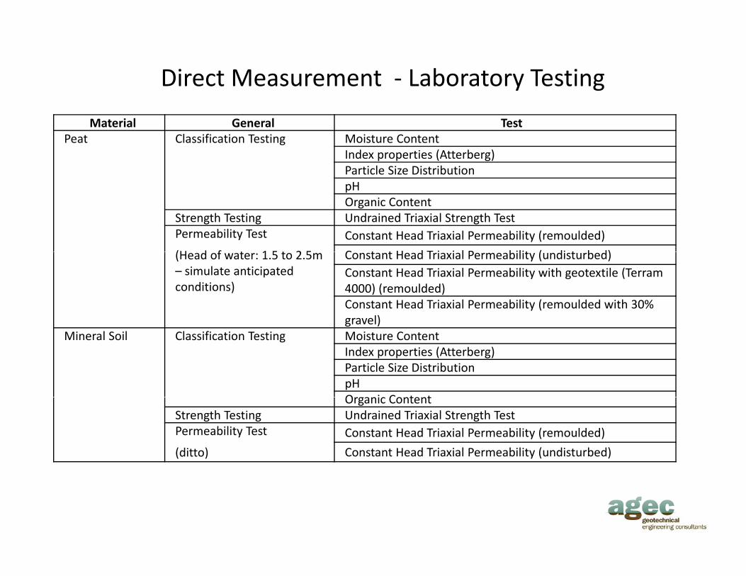
Direct Measurement ‐ Laboratory Testing
Material General TestPeat Classification Testing Moisture Content
Index properties (Atterberg)Particle Size DistributionpHOrganic Content
Strength Testing Undrained Triaxial Strength TestPermeability Test
(H d f t 1 5 t 2 5
Constant Head Triaxial Permeability (remoulded)
C t t H d T i i l P bilit ( di t b d)(Head of water: 1.5 to 2.5m – simulate anticipated conditions)
Constant Head Triaxial Permeability (undisturbed)Constant Head Triaxial Permeability with geotextile (Terram 4000) (remoulded)Constant Head Triaxial Permeability (remoulded with 30% gravel) g )
Mineral Soil Classification Testing Moisture ContentIndex properties (Atterberg)Particle Size DistributionpHOrganic ContentOrganic Content
Strength Testing Undrained Triaxial Strength TestPermeability Test
(ditto)
Constant Head Triaxial Permeability (remoulded)
Constant Head Triaxial Permeability (undisturbed)

Direct Measurement ‐ Insitu Testing
• Undisturbed (intact) peat
‐ Piezometer measurement
‐ 2 test areas in undisturbed peat adjacent/on route
‐ 12 nos. piezometers
‐ Large scale k‐testsLarge scale k tests
‐ 4 no. large diameter pipes tests (T1, T2, T3, & T4)
• Reworked (disturbed/remoulded) peat:
‐ Piezometer measurement
‐ 3 sites with placed reworked peat
‐ 21 nos piezometers‐ 21 nos. piezometers
‐ Tank test
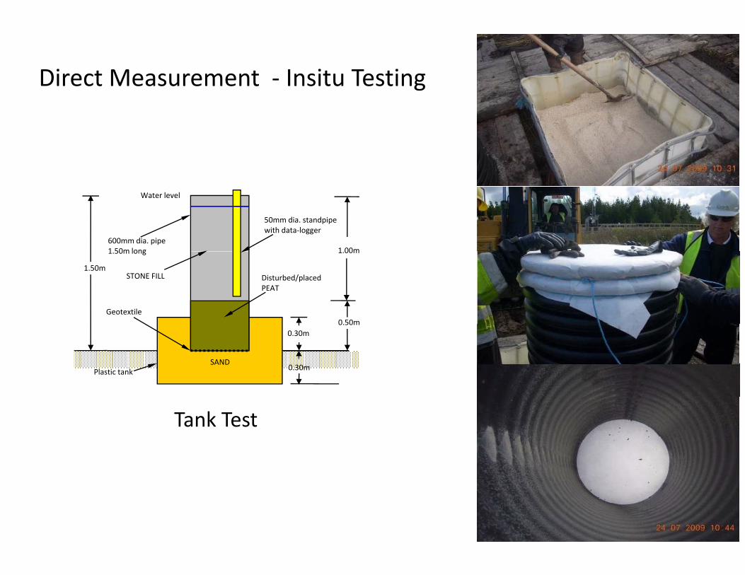
Direct Measurement ‐ Insitu Testing
50mm dia. standpipe with data‐logger
Water level
600mm dia. pipe 1 50m long 1 00m
Disturbed/placed PEAT
STONE FILL
Geotextile
1.50m long
0 50m
1.00m
1.50m
SAND
0.50m
0.30m
0.30m
Plastic tank
Tank Test
22
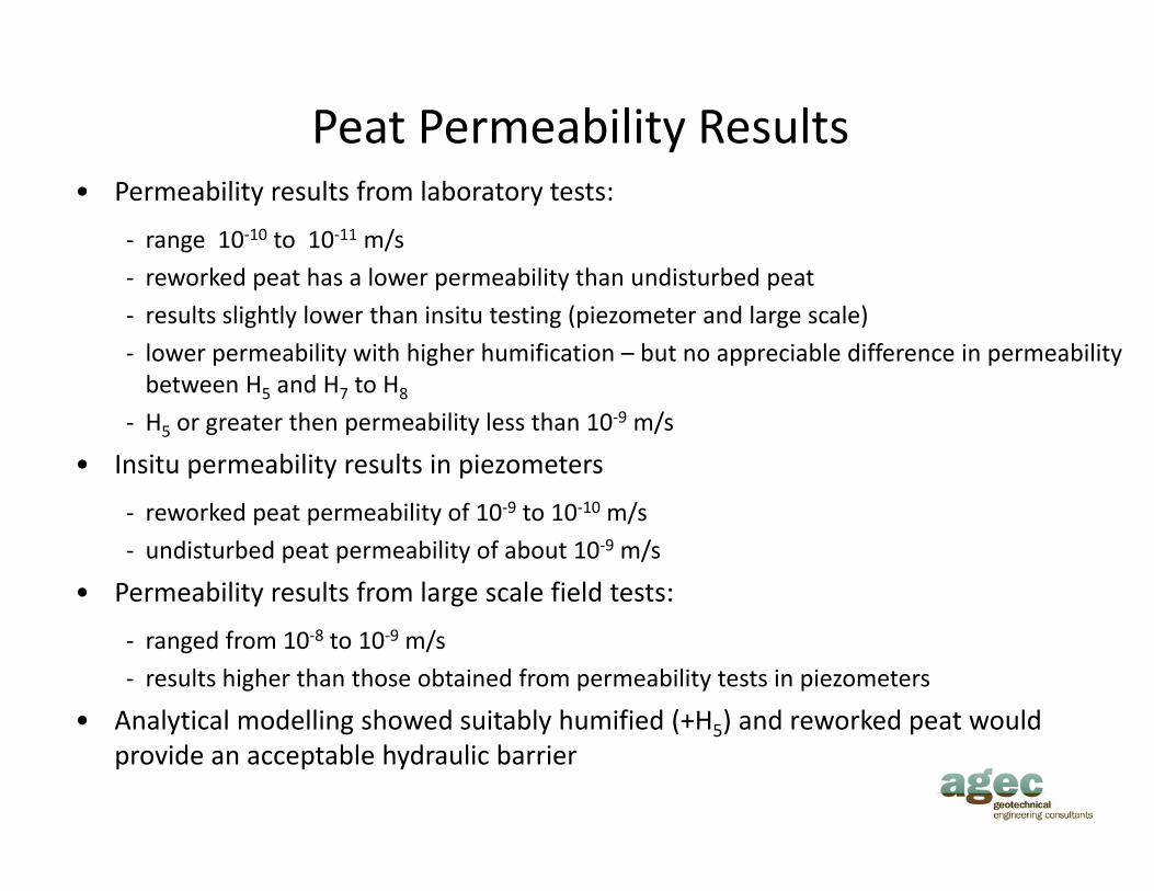
Peat Permeability Results• Permeability results from laboratory tests:
‐ range 10‐10 to 10‐11 m/s
reworked peat has a lower permeability than undisturbed peat‐ reworked peat has a lower permeability than undisturbed peat
‐ results slightly lower than insitu testing (piezometer and large scale)
‐ lower permeability with higher humification – but no appreciable difference in permeability between H5 and H7 to H8between H5 and H7 to H8
‐ H5 or greater then permeability less than 10‐9 m/s
• Insitu permeability results in piezometers9 10 /‐ reworked peat permeability of 10‐9 to 10‐10 m/s
‐ undisturbed peat permeability of about 10‐9 m/s
• Permeability results from large scale field tests:
‐ ranged from 10‐8 to 10‐9 m/s
‐ results higher than those obtained from permeability tests in piezometers
• Analytical modelling showed suitably humified (+H5) and reworked peat wouldAnalytical modelling showed suitably humified (+H5) and reworked peat would provide an acceptable hydraulic barrier
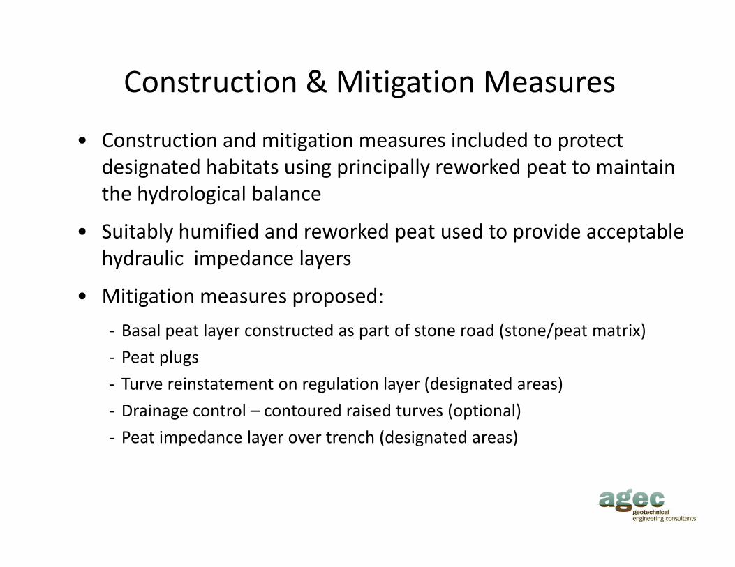
Construction & Mitigation Measures
• Construction and mitigation measures included to protect designated habitats using principally reworked peat to maintain g g p p y pthe hydrological balance
• Suitably humified and reworked peat used to provide acceptable hydraulic impedance layers
• Mitigation measures proposed:
‐ Basal peat layer constructed as part of stone road (stone/peat matrix)
‐ Peat plugs
‐ Turve reinstatement on regulation layer (designated areas)g y ( g )
‐ Drainage control – contoured raised turves (optional)
‐ Peat impedance layer over trench (designated areas)
Stone road construction and basal peat layer (peat/stone matrix)
Peat plugs
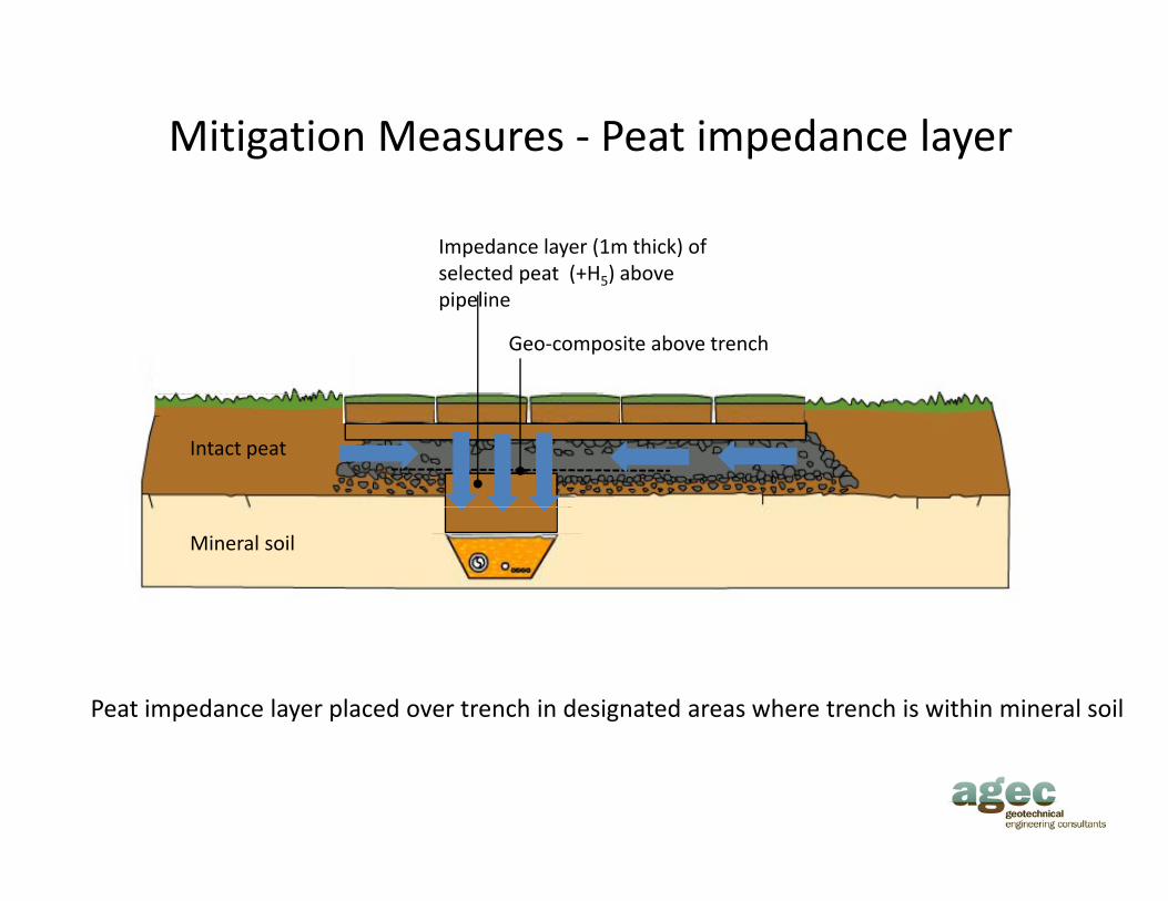
Mitigation Measures ‐ Peat impedance layer
Impedance layer (1m thick) of selected peat (+H5) above
Geo‐composite above trench
p ( 5)pipeline
Intact peat
Mineral soil
Peat impedance layer placed over trench in designated areas where trench is within mineral soil

Finish
Acknowledgements
Sh ll E&P I l d Li it dShell E&P Ireland Limited
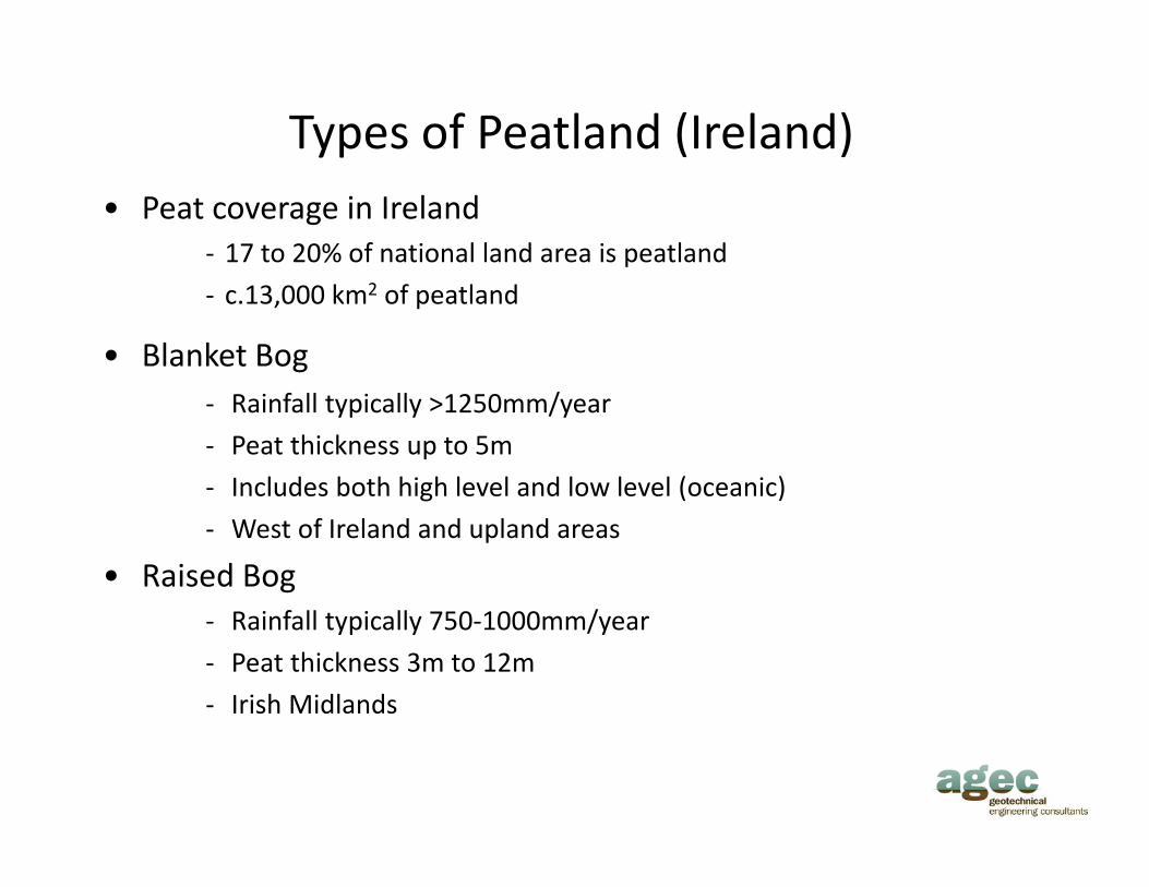
Types of Peatland (Ireland)• Peat coverage in Ireland
‐ 17 to 20% of national land area is peatland
‐ c.13,000 km2 of peatland
• Blanket Bog‐ Rainfall typically >1250mm/year
‐ Peat thickness up to 5m
‐ Includes both high level and low level (oceanic)g ( )
‐ West of Ireland and upland areas
• Raised BogR i f ll i ll 750 1000 /‐ Rainfall typically 750‐1000mm/year
‐ Peat thickness 3m to 12m
‐ Irish Midlands