Lanthanides in Organic Synthesis - Princeton University - Home
Written while at Molycorp, Inc., White Plains, NY USA
Current information: 8505 E. Temple Drive, Unit 474, Denver, CO 80237 USA Tel. +1-303-955-8537, Cell +1-317-514-5920, e-mail: [email protected] www.spontaneousmaterials.com
79
PERMANENT MAGNETS BASED ON THE LANTHANIDES
Raw Materials, Processing and Properties
S. R. Trout
Abstract
Lanthanide based permanent magnets, Sm-Co and Nd-Fe-B type magnets are reviewed. The historical progression of materials over the last fifty years is traced. The lanthanides and their idiosyncrasies are covered. Processing technologies are discussed and some observations about the future of these materials are made.
Introduction
Permanent magnets based on the lanthanides, Sm-Co and Nd-Fe-B, are exciting additions to the family of magnetic materials, from many perspectives. To the materials scientist, they are a new generation of lanthanide-based intermetallic materials, with excellent magnetic properties. To the electrical engineer, they are powerful components in designing new devices with greatly enhanced performance. To the magnet producer, they are new permanent magnet materials, with improved magnetic properties and several processing options.
History Using a lanthanide element in permanent magnets is hardly a new concept. The first work in this area was published in 1935, when Urbaine, et al. reported that gadolinium is ferromagnetic. [1] Some of the lanthanides have record magnetic moments, but unfortunately their Curie temperatures are at or far below room temperature. Commercialization of the lanthanides occurred as a result of the Manhattan Project, when the technology for large scale separation of the lanthanides, as well as the actinides, was developed. Since the end of the Second World War, scientists and engineers have had access to reasonable quantities of high purity lanthanide elements and have
80
systematically studied the many unique properties, not just magnetic, of these elements and their alloys. By the mid 1960's, LnCo5 compounds (Ln being any lanthanide) had been recognized as excellent candidates for permanent magnet materials, due to their high magnetocrystalline anisotropy and moderate saturation magnetization. [2, 3, 4] Primary interest focused on the light lanthanides, i.e. La, Ce, Pr, Nd, Sm and Y, even though the light lanthanide generally have smaller magnetic moments than the heavy lanthanides. In the LnCo5 structure, the heavy lanthanide moment couples antiferromagnetically with the cobalt moment, reducing the saturation magnetization. The first SmCo5 magnets appeared in the late 1960's and early 1970's, due to the research and development efforts of several organizations, most notably: General Electric, Raytheon, Bell Telephone Laboratories, Wright Patterson Air Force Base, N. V. Philips and Brown Boveri et Cie. As soon as SmCo5 became a commercially viable permanent magnet, research began in two directions. One direction was to replace or reduce the amount of samarium in the alloy, by substituting one or more of the more abundant and less expensive lanthanides: Ce, La, Nd, Pr and MM, where MM is mischmetal. The other direction was to replace the cobalt with iron, since iron is less expensive and has a slightly larger magnetic moment per atom than cobalt. In both cases, the goal was to reduce the cost of the magnet, by reducing the raw material cost, without adversely affecting the magnetic properties. Four distinct alloys have evolved from this research. The first material is MMCo5. Mischmetal is far less expensive than samarium, by about a factor of 15. However, the magnetic properties of MMCo5 magnets are drastically poorer than SmCo5 magnets, to the point that the tradeoff of magnetic properties versus alloy cost is unfavorable for MMCo5. Similar behavior was also observed for CeCo5, LaCo5 and NdCo5. [3] The main fault is that the anisotropy is much lower for these compounds, making difficult to obtain acceptable Hci levels. [5] The second material is SmxPr(1-x)Co5. Praseodymium is more abundant, less expensive and has a slightly larger magnetic moment than samarium. A partial substitution of Pr for Sm actually improves Br and (BH)max. However, as the Pr/Sm ratio increases above 1, the stability of the alloy above room temperature is reduced and it is difficult to keep Hci as high as it is in SmCo5. Therefore, most commercial materials have a Pr/Sm under 0.5, for a good combination of magnetic properties and raw material cost. Some research continues to try to make a PrCo5 magnet, but nothing is commercial as of this writing. [6, 7] The third material is the Sm2(Co, Fe, Cu, Zr or Hf)17 alloy system, here after referred to a 2-17 magnets. This is a metallurgically complicated alloy system, with high Hci based on precipitation hardening. In these alloys, both the samarium and the cobalt levels are reduced, while the magnetic properties are generally superior to SmCo5. The major drawback to 2-17 magnets is their complicated processing, due in part to the fact that the alloy has at least 5 components, which must be held to tight tolerances. In production, it is difficult to obtain the desired microstructure for the best magnetic properties. Also, the heat treatments are much longer and more complicated than the heat treatment of SmCo5. The limited availability of 2-17 magnets stem from these complications. [8]

81
The fourth material is Nd2Fe14B, which achieves the original goals of replacing Sm and Co in SmCo5 magnets. The magnetic properties of the binary lanthanide-iron compounds, including Nd-Fe, were examined at about the same time as the lanthanide-cobalt systems, in the 1960's and early 1970's. However, all the binary lanthanide-iron alloys have at least one of the following problems, making them unsuitable as permanent magnets. The problems are: 1) a Curie temperature near or below room temperature, 2) unfavorable anisotropy, usually an easy cone or an easy plane, or 3) antiferromagnetic coupling between the lanthanide and the iron magnetic moments, resulting in low saturation magnetization. The critical addition of the metalloid element boron to the Nd-Fe alloy, results in a slightly expanded crystal structure, overcoming the above mentioned drawbacks of the lanthanide-iron alloys. At almost the same time in 1983, several groups reported independently, excellent permanent magnet properties based on the Nd-Fe-B alloy system. [9, 10, 11, 12, 13] Commercial production of these materials started almost immediately thereafter.
The Lanthanides The lanthanides consist of elements number 57, lanthanum, through 71, lutetium, at the bottom of the periodic table. These elements have historically been called the rare earths, but this name is misleading, as they are neither rare like gold or earths like magnesium or calcium. At the time these elements were discovered, rare was an apt term. However, several large deposits are found all over the world. Figure 1 shows the relative abundance of some of the lanthanides compared to other elements. Cerium, the most abundant lanthanide, is more common in the earth's crust than nickel. Lanthanum, the second most abundant lanthanide, is more common than lead or tin. [14, 15]
Figure 1. Relative abundance of various elements in the earth’s crust
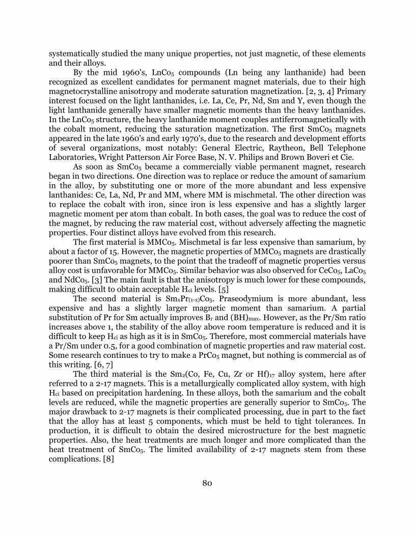
Lanthanides are unusual in that they are all found together in the ore. Figure 2 shows the breakdown of the most common lanthanide ores, Bastnasite and Monazite. In both ores, two general observations can be made about relative abundance. The abundance of the even atomic numbered elements is greater than the odd atomic numbered elements on either side and abundance diminishes with increasing atomic number, odd or even.
82
The periodic table shows that in the lanthanide series, the inner 4f electron shell is being filled from lanthanum to lutetium. This in part explains some of the facts known about the lanthanides.
1. Chemically the lanthanides are all very similar since there is little difference in the outer electron configuration.
2. The lanthanide oxides are extremely stable since the outer electrons are easily
removed from the metals. The metallic form of any lanthanide is not found in nature. Lanthanides are always found as compounds, usually a complex oxide or fluoride.
3. Because the lanthanides are chemically similar and are found together in the ore,
their separation is difficult. Use of separated lanthanides, as oxides, metals or salts, has grown tremendously in the last 25 years. There are two principal methods for separating lanthanides, solvent extraction and ion exchange. Purities as high as 99.999% can be obtained with either technique.
Figure 2. Breakdown of the lanthanides in the two most common ores.

83
Lanthanide metals are generally reduced by calciothermic reduction of a salt, usually fluoride or chloride. The exceptions are samarium and europium, which due to their low boiling point are distilled in the presence of mischmetal. Electrolytic techniques may also be used to produce the metals. This technique is cost effective only at relatively large production volumes. Historically, electrolytic reduction of the lanthanides to metals has been used mainly to produce mischmetal.
Processing There are several ways to make lanthanide based permanent magnets. We will start with the conventional powder metallurgy method, concentrating on Nd-Fe-B, and compare the other processing methods to the powder metallurgy approach. A block diagram of the powder metallurgy process is shown in figure 3. The first step is the vacuum melting of neodymium, iron and ferroboron to the correct composition. Melting in an inert atmosphere is required since molten neodymium is readily oxidized when exposed to air. The desired composition is just slightly richer in Nd than the Nd2Fe14B stoichiometry, to offset the preferential oxidation of Nd and to retain a small amount of an Nd-rich phase in the grain boundaries of the magnet. During vacuum melting, the iron and ferroboron are melted first in vacuum. Neodymium is added after the iron and ferroboron are molten and after the atmosphere has been changed to argon. The argon atmosphere is necessary to reduce the vaporization of the molten Nd. The molten alloy is poured into
Figure 3. Powder Metallurgy Method
Raw Materials
Vacuum Melt
Crush
Mill
Press Align
Sinter
Heat Treat
84
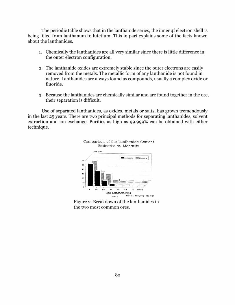
a mold. Like most lanthanide-transition metal alloys, as-cast Nd-Fe-B is brittle and is easily broken with a hammer, as the first step in making powder. The broken pieces are crushed to about 250 m by a pulverizer and reduced to final size by milling. The optimum particle size is in the 2 to 4 m range, as measured by the Fisher Sub Sieve Sizer. A jet, ball or vibratory mill can be used for this step. Both crushing steps are done in an inert atmosphere, usually argon or nitrogen. The critical point is that at the optimum particle size nearly all the powder consists of particles that are single crystals. This is a necessary condition for magnetic aligning. Powder milled to less than the optimum particle size is more prone to oxidation, sometimes rapid, making it difficult to handle and not suitable for magnet making. Magnets are shaped and the powder is aligned by die pressing. In one operation, the powder is aligned and pressed in a three step process. In step one, the powder is filled into the die cavity. The tooling is moved to the top of the die cavity, but no pressure is applied. In step two, a magnetic field is applied to the powder. Because the particles are nearly all single crystals, each particle rotates so that its easy direction is nearly parallel to the applied magnetic field. In step three, the powder is compacted by the tooling and the magnetic field is reversed to demagnetize the tooling. Pressing begins the process of making the magnet material dense. The densification process is completed by sintering, typically a density of 7.4 to 7.5 g/cm3 can be achieved, compared to the theoretical density of 7.6 g/cm3. Typical sintering conditions are vacuum, 1080 oC for 2 hours, followed by a quench to room temperature. Sintering completes the process of densification, but does not develop the optimum magnetic properties. As figure 4 shows, Hci, Hk and Hc can all be improved by a post sintering heat treatment. A typical heat treatment is one hour at 600 oC, followed by a rapid quench to room temperature.
Figure 4. Effect of heat treatment on demagnetization curves for a typical Nd-Fe-B magnet.

85
Hydrogen decrepitation (hydriding) While the as-cast Nd-Fe-B alloy is brittle and easily broken, ductility is readily apparent during the crushing step. Crushing as-cast alloy to a size less than 250 m is not easy. As a result, the alloy can oxidize excessively during this step. An improvement on the conventional powder metallurgy process is hydrogen decrepitation or hydriding. [16] Alloy is exposed to hydrogen gas, usually at a slightly elevated temperature and/or elevated pressure, to increase the reaction rate. Hydrogen diffuses into the alloy, making it brittle and causing it to literally fall apart. The resulting material is a coarse powder and with very little effort, it can be crushed to a size less than 250 m, before milling. Hydrogen decrepitation was applied earlier to Sm-based alloys by Harris, but the approach is more useful in the Nd-Fe-B alloy system. [17] The principal advantage of hydriding is that the difficulty of the crushing step is greatly reduced. Since hydriding greatly reduces the ductility of the material, far less mechanical work is required to crush the alloy, reducing the extent of alloy oxidation. Some work has been done on using hydriding to replace both crushing and milling. However, it is difficult to obtain a particle size below 5 m by hydriding alone, with a particle size distribution as narrow as other milling methods. With a combination of hydriding and conventional grinding techniques, it may be possible to make further improvements in powder making. The mechanism of hydriding is not completely understood, however the most likely explanation is that hydrogen rapidly diffuses through the grain boundaries of as-cast alloy. The absorbed hydrogen expands the lattice of the grain boundary phases and fractures the alloy from within. Alloys that are slightly rich in Nd, which contain an Nd-rich phase in the grain boundary, seem to hydride with greater ease. Rapidly quenched materials which are generally nearer the stoichiometric composition do not hydride as easily.
Reduction/Diffusion The reduction/diffusion (R/D) process was developed for the production of SmCo5 alloys by Cech. [18] A very similar process called co-reduction was developed by Herget and Domazer. [19] Both processes are in commercial use today. The first SmCo5 alloys were made by vacuum melting in a fashion similar to the process described in figure 3. There are two important differences between Nd-Fe-B and SmCo5 in the alloy making process. First samarium metal cannot be made by the direct reduction of its oxide or salts; it must be sublimed in the presence of mischmetal and condensed on a tantalum cone. This is a more expensive process than calciothermic reduction. Second roughly 10% of the samarium is vaporized and lost during vacuum melting. Thus the production of SmCo5 by vacuum melting the metals is expensive. The R/D method overcomes both of these problems and also has the advantage that the alloy is produced in a powder form, ready for milling. The reaction is
Sm2O3 + 10 Co + 3 Ca 3 CaO + 2 SmCo5
86
The reaction takes place at 1100 oC for 1 to 4 hours in a hydrogen atmosphere. Usually an excess amount of Ca is added, typically 20 to 40% to assure that the reaction goes to completion. The R/D method has also been applied to the Nd-Fe-B system with limited success. A major problem has been the solubility of Nd in the water used by the washing step to remove the reacted Ca. [20, 21]
Atomization Atomization combines to alloying and powder making steps, by spraying the molten Nd-Fe-B alloy into small particles before quenching them in a suitable media, usually a cryogenic fluid, nitrogen or argon. The spraying allows the particles size to be well controlled. The quenching permits rapid solidification without time for segregation of secondary phases. Although the quenching does not take place at a fast enough rate to create amorphous material. The particle size after atomization is in the 10 to 40 m range. Further grinding is necessary to obtain the optimum particle size. Atomization seems to have the advantage of delivering a narrow range of particle sizes, but it has the disadvantage of being a capital intensive process.
Rapid solidification Rapid solidification has been used for many years for making a wide variety of materials. The original patents for this technique were issued around 1900. Molten alloy is forced onto a moving surface, quenching the liquid into a solid with cooling rates of 106 K/second. A popular use of rapid solidification has been to make the magnetically soft amorphous alloys. Rapid solidification was applied by several groups to Nd-Fe-B. [10, 11, 12] Rapidly quenched Nd-Fe-B usually is produced in the form of microcrystalline flakes. The grains are isotropically oriented and several hundred Angstroms in diameter. Usually annealing is required to obtain the optimum grain size. The Nd-Fe-B rapidly quenched flakes can be bonded, hot pressed or hot worked into magnets. The bonded and hot pressed magnets are isotropic, while hot worked magnets are oriented.
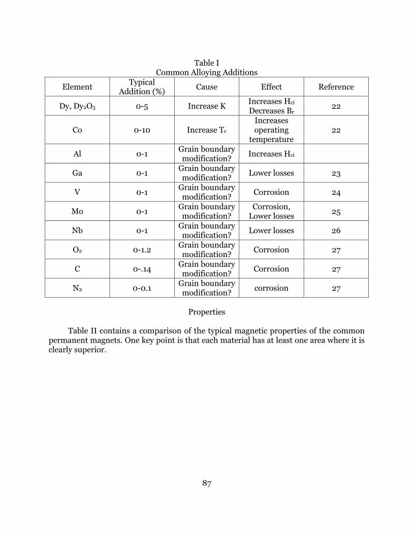
The effect of individual alloying elements One of the more interesting aspects of the development of Nd-Fe-B magnets has been the usefulness of small additions of several alloying elements. Most of the periodic table has been tried to improve the performance of the basic alloy, in some respect. Table I summarizes the most popular alloying elements and attempts to assign a mechanism on their influence. Many elements are effective at very low addition levels, up to 1% by weight, indicating that these elements are influencing the grain boundary phases. Other elements like Co and Dy require larger substitutions to be useful and seem to be substituting in the matrix phase for Fe and Nd, respectively.
87
Table I
Common Alloying Additions
Element Typical
Addition (%) Cause Effect Reference
Dy, Dy2O3 0-5 Increase K Increases Hci Decreases Br
22
Co 0-10 Increase Tc Increases operating
temperature 22
Al 0-1 Grain boundary modification?
Increases Hci
Ga 0-1 Grain boundary modification?
Lower losses 23
V 0-1 Grain boundary modification?
Corrosion 24
Mo 0-1 Grain boundary modification?
Corrosion, Lower losses
25
Nb 0-1 Grain boundary modification?
Lower losses 26
O2 0-1.2 Grain boundary modification?
Corrosion 27
C 0-.14 Grain boundary modification?
Corrosion 27
N2 0-0.1 Grain boundary modification?
corrosion 27
Properties
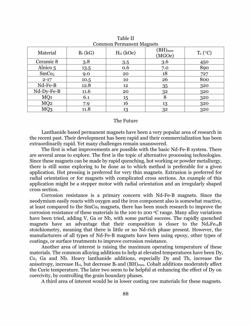
Table II contains a comparison of the typical magnetic properties of the common permanent magnets. One key point is that each material has at least one area where it is clearly superior.
88
Table II
Common Permanent Magnets
Material Br (kG) Hci (kOe) (BH)max (MGOe)
Tc (C)
Ceramic 8 3.8 3.5 3.6 450 Alnico 5 13.5 0.6 7.0 890 SmCo5 9.0 20 18 727
2-17 10.5 10 26 800 Nd-Fe-B 12.8 12 35 320
Nd-Dy-Fe-B 11.6 20 32 320 MQ1 6.1 15 8 320 MQ2 7.9 16 13 320 MQ3 11.8 13 32 320
The Future
Lanthanide based permanent magnets have been a very popular area of research in the recent past. Their development has been rapid and their commercialization has been extraordinarily rapid. Yet many challenges remain unanswered. The first is what improvements are possible with the basic Nd-Fe-B system. There are several areas to explore. The first is the topic of alternative processing technologies. Since these magnets can be made by rapid quenching, hot working or powder metallurgy, there is still some exploring to be done as to which method is preferable for a given application. Hot pressing is preferred for very thin magnets. Extrusion is preferred for radial orientation or for magnets with complicated cross sections. An example of this application might be a stepper motor with radial orientation and an irregularly shaped cross section. Corrosion resistance is a primary concern with Nd-Fe-B magnets. Since the neodymium easily reacts with oxygen and the iron component also is somewhat reactive, at least compared to the SmCo5 magnets, there has been much research to improve the corrosion resistance of these materials in the 100 to 200 oC range. Many alloy variations have been tried, adding V, Ga or Nb, with some partial success. The rapidly quenched magnets have an advantage that their composition is closer to the Nd2Fe14B stoichiometry, meaning that there is little or no Nd-rich phase present. However, the manufacturers of all types of Nd-Fe-B magnets have been using epoxy, other types of coatings, or surface treatments to improve corrosion resistance. Another area of interest is raising the maximum operating temperature of these materials. The common alloying additions to help at elevated temperatures have been Dy, Co, Ga and Nb. Heavy lanthanide additions, especially Dy and Tb, increase the anisotropy, increase Hci, but decrease Br and (BH)max. Cobalt additions moderately affect the Curie temperature. The later two seem to be helpful at enhancing the effect of Dy on coercivity, by controlling the grain boundary phases. A third area of interest would be in lower costing raw materials for these magnets.
89
The most expensive element used in these alloys is dysprosium. At the same time, adding Dy decreases Br and (BH)max slightly. One would like to be able to remove or reduce the amount of Dy, maintain the same values of Hci, and increase Br and (BH)max. Another approach to lower cost raw materials is the substitution of less expensive lanthanides for neodymium. There are three possible substitutions, cerium, lanthanum, or a mixed lanthanide. Cerium substitution seems to be out of the question because of the lower magnetic moment of Ce and the decrease in Hci that would result. Lanthanum substitutions are not as bad as cerium, but are not well supported by the literature, since there are data showing that La2Fe14B does not have uniaxial anisotropy. However, partial substitutions of La-rich mixtures for part or all of the Nd may work and raise the possibility of using a Ce-reduced or a Ce-free mischmetal as a substitute for neodymium. Since the introduction of the Nd2Fe14B system, a new permanent magnet alloy system has been introduced, namely SmFeTi10. [28] This seems to be a similar crystal structure as Nd2Fe14B, but has the problem of using samarium as the lanthanide component. It does have the advantage of a higher Curie temperature and may well be capable of much better performance than Nd-Fe-B, either because of higher operating temperatures, or lower cost, if the Sm can be replaced with a less expensive lanthanide. Another area of future interest and concern is the handling of scrap materials, falling into three main categories. One is material left in the furnace after vacuum melting, atomizing or rapid quenching. The second is rejected finished magnets. The third is the residue from the grinding operations used to fabricate the magnets to their final physical dimensions. The reasons for interest in these materials are twofold. They have some commercial value due to the content of Nd and in some cases Dy. Without any way to recycle them, scrap materials are handled as hazardous wastes, which add to the cost of manufacture. Several recycling methods have been proposed, but the economics and viability of them has, so far, proven unsatisfactory. The first is to try to remelt these materials, attempting to recover the metallic, unoxidized, lanthanide content. In general, the yield from this process is very low from any of the three types of scrap. Although for melting residue, there may be enough of a recovery to be economical. The second approach is to try to reduce the scrap materials completely to the oxide state and recover the lanthanide component chemically. This approach and its variations are not completely tested, but appear to be the only way to handle these materials, meaning their commercial value is nearly zero. In short, there are a few problems to be addressed, but we have many exciting opportunities with permanent magnets based on the lanthanides.
References 1. G. W. Urbain, P. Weiss and F. Trombe, Compte Rendus 200 2132 (1935). 2. K. Nassau, L. V. Cherry and W. E. Wallace, J. Phys. Chem. Solids 16 123 (1960). 3. E. A. Nesbitt and J. H. Wernick, Rare Earth Permanent Magnets, Academic Press,
New York (1973). 4. G. Hoffer and K. J. Strnat, IEEE Trans. Magnetics 2 487 (1966).

90
5. H. Nagel and A. Menth, Goldschmidt Informiert 35 42 (1975). 6. W. E. Wallace, R. S. Craig, H. O. Gupta, S. Hirosawa, A Pedziwiatr, E. Oswald and E.
Schwab, IEEE Trans. Magnetics 20 1599 (1984). 7. M. H. Ghandehari, R. E. Golden and K. L. McNutt, IEEE Trans. Magnetics 20 1611
(1984). 8. A. E. Ray, W. A. Soffa, J. R. Blachere and B. Zhang, IEEE Trans. Magnetics 23 2714
(1987). 9. M. Sagawa, S. Fujimura, N. Togawa, H. Yamamoto and Y. Matsuura, J. Applied
Physics 55 2083 (1984). 10. J. J. Croat, J. F. Herbst, R. W. Lee and F. E. Pinkerton, J. Applied Physics 55 2079
(1984). 11. G. C. Hadjipanayis, R. C. Hazelton and K. R. Lawless, J. Applied Physics 55 2073
(1984). 12. Joseph J. Becker, J. Applied Physics 55 2067 (1984). 13. N. C. Koon and B. N. Das, J. Applied Physics 55 2063 (1984). 14. B. T. Kilbourn, J. of Metals, May 22 (1988). 15. J. B. Hedrick, Ceramic Bulletin 67 858 (1988). 16. I. R. Harris, C. Noble and T. Bailey, J. Less-Common Metals, 106 (1985) L1. 17. I. R. Harris, J. Evans and P. S. Nyholm, UK Patent 1,554,384 (October 1979). 18. R. E. Cech, J. Metals 26 32 (1974). 19. C. Herget and H. G. Domazer, Goldschmidt Informiert 35 3 (1975). 20. C. Herget, Proc. 8th Intl. Workshop on Rare Earth Perm. Magnets, (ed. K. J. Strnat)
Dayton, Ohio, 407 (1985). 21. R. A. Sharma, J. Metals 39 (2) 33 (1987). 22. M. Sagawa, S. Fujimura, H. Yamamoto, Y. Matsuura and K. Hiraga, IEEE Trans.
Magnetics 20 1584 (1984). 23. M. Endoh, M. Tokunaga and H. Harada, IEEE Trans. Magnetics 23 2290 (1987). 24. P. Tenaud, F. Vial and M. Sagawa, IEEE Trans. Magnetics 26 1930 (1990). 25. Xufang Shen, Yongqiang Wang, Zhitao Diao and Xuefen Liu, J. Applied Physics 61
3433 (1987). 26. M. Tokunaga, H. Harada and S. R. Trout, IEEE Trans. Magnetics 23 2284 (1987). 27. A. S. Kim, F. E. Camp and E. J. Dulis, IEEE Trans. Magnetics 26 1936 (1990). 28. K. Ohashi, T. Yokoyama, R. Osugi and Y. Tawara, IEEE Trans. Magnetics 23 3101
(1987).

![V f - CNPEMpages.cnpem.br/wanc/wp-content/uploads/sites/91/... · [1] S. McAdams, A. Ariciu, A. Kostopulos, J. Walsh, F. Tuna, Molecular single-ion magnets based on lanthanides and](https://static.fdocuments.us/doc/165x107/5f2f14014796ab7779117461/v-f-1-s-mcadams-a-ariciu-a-kostopulos-j-walsh-f-tuna-molecular-single-ion.jpg)