Permanent Magnetic Dc Motor
4
PRZEGLĄD ELEKTROTECHNICZNY (Electrical Review), ISSN 0033-2097, R. 87 NR 11/2011 267 Nadir BOUCHETATA 1 , Mohamed BOURAHLA 1 , Abdelmadjid MENAD 1 University of sciences and the technology of Oran (USTO) BP 1505 EL M’ naouer Oran, Algeria Experimental study of protection and control applied to Permanent Magnetic DC Motor Abstract. A century ago, steam engines, petroleum and power were competing to replace animal power. Whenever it was possible to feed continuously by an external source, moving vehicles, therefore, reserved lanes or shared, is electricity that has prevailed: subway, train, tram, trolley bus. For other autonomous vehicles that require a power source on board, fossil fuels and internal combustion engines have taken almost the entire market for obvious reasons of autonomy but not in the medical field. Streszczenie. W artykule analizowano silnik prądu stałego w zastosowaniach napędowych. Zaproponowano metody zabezpieczeń i sterowania tym silnikiem. (Badania systemów zabezpieczeń i sterowania silnikiem prądu stałego) Keywords: Microcontroller, Permanent magnetic DC motor, Electrical vehicle, Protection and Control. Słowa kluczowe: silnik prądu stałego, sterowanie, zabezpieczenia. Introduction The DC machine is a rotating electric machine that operates completely reversible, as its name suggests, from a voltage and a direct current. In the context of small engines, it is suitable for electrochemical power sources. For high power, it operates as a motor (traction), converter of electrical energy into mechanical energy or as a generator (braking), and converter of mechanical energy into electrical energy. This machine is an electromechanical converter. If you will consider it an achievement for controlling a DC motor with permanent magnet excitation designated for a wheelchair for disabled. The power part Fig.1 Block diagram of the power part It consists of five elements: The first element is the continuous supply of trained several batteries. In the embodiment will be in our hands with power is rectified filtered 180V. The second element is the static inverter which will be a series converter (step down converter) consists of a cell switching power (MOSFET) and a freewheeling diode (LED fast) with galvanic isolation between this part of power and control. [1] [2] The fig.2 shows clearly different from the side power and choice of components used. Fig.3 Photograph of the power section performed The third element is the engine like PERMANENT dc power of 1HP with armature voltage of 180V and 4.9A current brand LEROYER SOMER. Fig.4 Engine used in handling Fig.2 Schematic of the electric power part The fourth element is a load; it will be the resisting torque (the weight of the wheelchair and person with disabilities) as a cross tender. Fig.5 load or load torque used Power DC Load Choper series P.M.D.C Motor Speed sensor
-
Upload
luis-florian-salas -
Category
Documents
-
view
245 -
download
4
Transcript of Permanent Magnetic Dc Motor
PRZEGLĄD ELEKTROTECHNICZNY (Electrical Review), ISSN 0033-2097, R. 87 NR 11/2011 267
Nadir BOUCHETATA1, Mohamed BOURAHLA1, Abdelmadjid MENAD1
University of sciences and the technology of Oran (USTO) BP 1505 EL M’ naouer Oran, Algeria
Experimental study of protection and control applied to Permanent Magnetic DC Motor
Abstract. A century ago, steam engines, petroleum and power were competing to replace animal power. Whenever it was possible to feed continuously by an external source, moving vehicles, therefore, reserved lanes or shared, is electricity that has prevailed: subway, train, tram, trolley bus. For other autonomous vehicles that require a power source on board, fossil fuels and internal combustion engines have taken almost the entire market for obvious reasons of autonomy but not in the medical field. Streszczenie. W artykule analizowano silnik prądu stałego w zastosowaniach napędowych. Zaproponowano metody zabezpieczeń i sterowania tym silnikiem. (Badania systemów zabezpieczeń i sterowania silnikiem prądu stałego) Keywords: Microcontroller, Permanent magnetic DC motor, Electrical vehicle, Protection and Control. Słowa kluczowe: silnik prądu stałego, sterowanie, zabezpieczenia. Introduction
The DC machine is a rotating electric machine that operates completely reversible, as its name suggests, from a voltage and a direct current. In the context of small engines, it is suitable for electrochemical power sources. For high power, it operates as a motor (traction), converter of electrical energy into mechanical energy or as a generator (braking), and converter of mechanical energy into electrical energy. This machine is an electromechanical converter. If you will consider it an achievement for controlling a DC motor with permanent magnet excitation designated for a wheelchair for disabled. The power part
Fig.1 Block diagram of the power part
It consists of five elements: The first element is the continuous supply of trained
several batteries. In the embodiment will be in our hands with power is rectified filtered 180V.
The second element is the static inverter which will be a series converter (step down converter) consists of a cell switching power (MOSFET) and a freewheeling diode (LED fast) with galvanic isolation between this part of power and control. [1] [2]
The fig.2 shows clearly different from the side power and choice of components used. Fig.3 Photograph of the power section performed
The third element is the engine like PERMANENT dc power of 1HP with armature voltage of 180V and 4.9A current brand LEROYER SOMER.
Fig.4 Engine used in handling
Fig.2 Schematic of the electric power part
The fourth element is a load; it will be the resisting torque (the weight of the wheelchair and person with disabilities) as a cross tender. Fig.5 load or load torque used
Power DC
Load
Choper series
P.M.D.CMotor
Speed sensor
268 PRZEGLĄD ELEKTROTECHNICZNY (Electrical Review), ISSN 0033-2097, R. 87 NR 11/2011
The fifth element is the speed sensor (stained metric generator) is used here just to observe the change in speed.
Fig.6 Generator stained metric
Fig.7 Schematic electrical packaging speed [6]
The following figure shows the circuit packaging for this size with a filter (R17, C1) to eliminate the noise generated by the mechanism of the mechanical generator.
(1) 1172
1
CRfc ith Hzfc 10
Fig.8 Photograph of part of the packaging speed THE CONTROL
Fig.9 The schematic diagram of the control part
It also consists of three elements:
The first element is set as a variable resistor (potentiometer) with another fix for not achieving the high speed action in this equation:
(2) cccom VRVRRV
RVRV
12111
121
This set point chosen so that it can vary the engine speed between the total and half of its nominal speed
Fig.10 Circuit diagram of the set The second element is the heart of the application, the
microcontroller (HCS12) which will acquire the deposit and the generation of PWM. [3] [4] [5]
Fig.11 Picture Card HCS12
The flowchart of the program used in the microcontroller is as follows:
Fig.12 The flowchart of the program
The third element is the protection against over current,
it is a current sensor with its conditioning circuit (adaptation and adjustment of gain by a resistance trimmer RV2) for observation in the current case or it may exceed its nominal value. [6]
Signal of the sensor of current
Consigne Microcontroller Protection
PWM towards the switch
PRZEGLĄD ELEKTROTECHNICZNY (Electrical Review), ISSN 0033-2097, R. 87 NR 11/2011 269
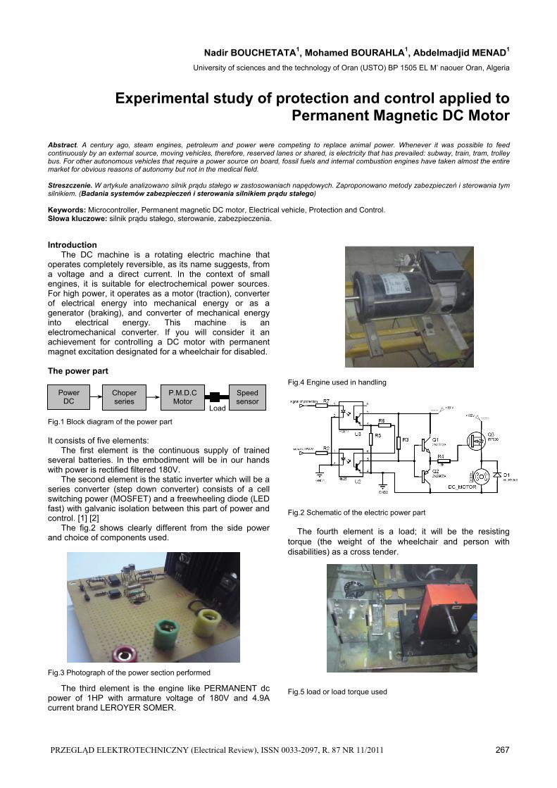
Fig.13 Circuit diagram of current sensor
Fig.14 Circuit diagram of current packaging Fig.15 Schematic electrical circuit for detecting excess current [6]
Fig.16 Photo of the part of protection against over current Scheme summary of the whole system
Fig.17 Schematic Of complete system
The fig.17 light assembly of all parts of the system.
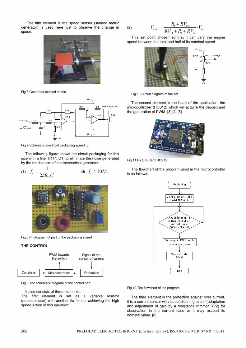
Fig.18 Assembly complete The results of the realization
After the completion and assembly of various parts of the prototype, we began testing and the following results:
Testing of protection against over current: In this maniple used a rheostat to resist 7A and our
calibration for the arrest was 3.6 A. CH1 (PWM) CH2 (G du MOSFET)
CH3 (signal of protection) CH4 (signal_I)
Fig. 19 Detection of excess power
Fig.20 Total cessation of MOSFET Test circuit of attack: After the fig.21 we see the optical
coupler acts as an inverter over its role galvanic isolation.
270 PRZEGLĄD ELEKTROTECHNICZNY (Electrical Review), ISSN 0033-2097, R. 87 NR 11/2011
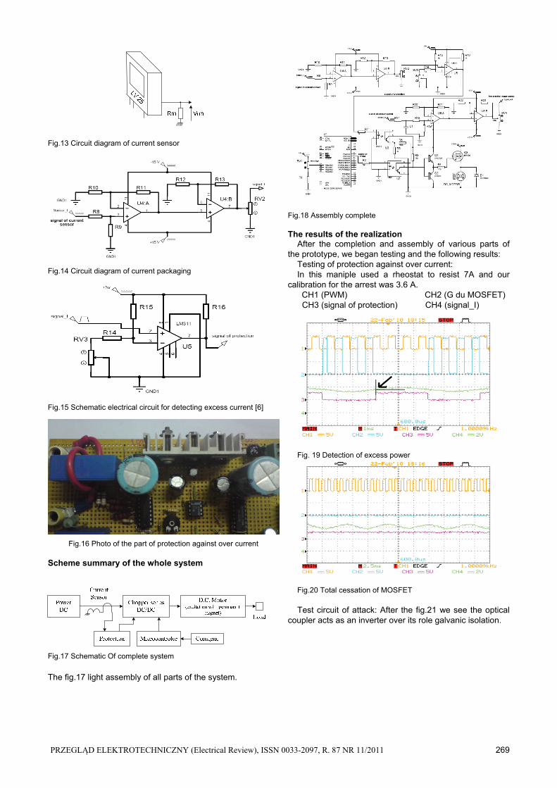
CH1 (PWM) CH2 (G du MOSFET)
Fig.21 PWM pulses and the Attack of the MOSFET
We noticed a delay in closing and opening of the optical
coupler, this problem does not affect our maniple because it uses a single power cell and not an arm of two cells.
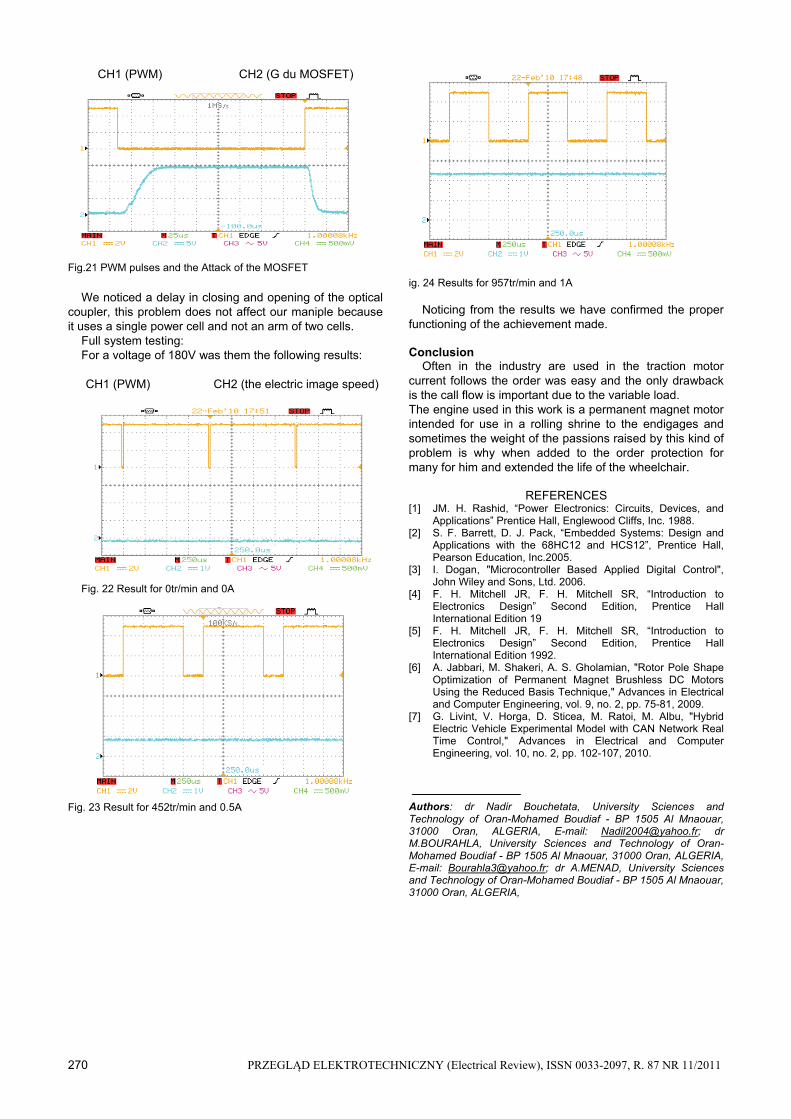
Full system testing: For a voltage of 180V was them the following results: CH1 (PWM) CH2 (the electric image speed)
Fig. 22 Result for 0tr/min and 0A
Fig. 23 Result for 452tr/min and 0.5A
ig. 24 Results for 957tr/min and 1A
Noticing from the results we have confirmed the proper functioning of the achievement made. Conclusion
Often in the industry are used in the traction motor current follows the order was easy and the only drawback is the call flow is important due to the variable load. The engine used in this work is a permanent magnet motor intended for use in a rolling shrine to the endigages and sometimes the weight of the passions raised by this kind of problem is why when added to the order protection for many for him and extended the life of the wheelchair.
REFERENCES [1] JM. H. Rashid, “Power Electronics: Circuits, Devices, and
Applications” Prentice Hall, Englewood Cliffs, Inc. 1988. [2] S. F. Barrett, D. J. Pack, “Embedded Systems: Design and
Applications with the 68HC12 and HCS12”, Prentice Hall, Pearson Education, Inc.2005.
[3] I. Dogan, "Microcontroller Based Applied Digital Control", John Wiley and Sons, Ltd. 2006.
[4] F. H. Mitchell JR, F. H. Mitchell SR, “Introduction to Electronics Design” Second Edition, Prentice Hall International Edition 19
[5] F. H. Mitchell JR, F. H. Mitchell SR, “Introduction to Electronics Design” Second Edition, Prentice Hall International Edition 1992.
[6] A. Jabbari, M. Shakeri, A. S. Gholamian, "Rotor Pole Shape Optimization of Permanent Magnet Brushless DC Motors Using the Reduced Basis Technique," Advances in Electrical and Computer Engineering, vol. 9, no. 2, pp. 75-81, 2009.
[7] G. Livint, V. Horga, D. Sticea, M. Ratoi, M. Albu, "Hybrid Electric Vehicle Experimental Model with CAN Network Real Time Control," Advances in Electrical and Computer Engineering, vol. 10, no. 2, pp. 102-107, 2010.
Authors: dr Nadir Bouchetata, University Sciences and Technology of Oran-Mohamed Boudiaf - BP 1505 Al Mnaouar, 31000 Oran, ALGERIA, E-mail: [email protected]; dr M.BOURAHLA, University Sciences and Technology of Oran-Mohamed Boudiaf - BP 1505 Al Mnaouar, 31000 Oran, ALGERIA, E-mail: [email protected]; dr A.MENAD, University Sciences and Technology of Oran-Mohamed Boudiaf - BP 1505 Al Mnaouar, 31000 Oran, ALGERIA,