PERMANENT JOINT APPLICATIONS - Orbitform · PDF filePERMANENT JOINT APPLICATIONS NON-PERMANENT...
5
Orbitform White Paper 1 800-957-4838 www.orbitform.com Assembly Solutions for Manufacturing Since 1984 PERMANENT JOINT APPLICATIONS NON-PERMANENT JOINT APPLICATIONS This article examines basic applications and considerations for common fastening and joining techniques used in permanent part assembly. There are many reasons products should not be taken apart: • Personal Safety - the product is inherently unsafe to repair. • Operational Safety – high product liability if the product fails during operation. • Extreme operating forces – high shock, vibration, Push- Pull, and Shear. • Regulatory requirements - part must be new, not repaired, required by law. • Warranty / Product integrity - part must be new and not repaired. • Modular assemblies – permanently assembled components. •Security/Tamper-proof/Vandalism – you don’t want anybody messin’ with it. Industries familiar with these concerns include: Automotive, Medical, Aerospace, Aviation, Electrical, Power Distribution, Safety, Military, and basically any products where lives are on the line and product liability is high, for example: Airbag Canisters, Mountain Climbing Gear, and Fire Extinguishers. If your product doesn’t need to be taken apart, and you’re using a non-permanent fastening method such as retaining rings, threaded fasteners, posts and cotter pins, etc., you may want to consider permanent assembly for some of the following reasons: • Reduce the cost of fastening hardware: retaining rings, threaded fasteners, nuts, washers, and cotter pins • Reducing the costs of machining operations: machining grooves and threads, drilling and tapping holes • Reducing the costs of assembly operations and cycle time: forming a rivet or post vs. installing a retaining ring, cotter pin, or driving a screw / nut • Superior retention - compared to cotter pins, retaining rings, and Loctite® • Improved aesthetics - Formed head versus bolt head, nut, screw head, cotter pin, or retaining ring. We recognize every application is different, and there is no “one size fits all” solution for permanent part assembly. On the next page is a matrix of fasteners & fastening processes, along with a few common joint requirements and costing considerations.
Transcript of PERMANENT JOINT APPLICATIONS - Orbitform · PDF filePERMANENT JOINT APPLICATIONS NON-PERMANENT...
Orbitform White Paper
1
800-957-4838www.orbitform.com
Assembly Solutions for Manufacturing Since 1984
PERMANENT JOINT APPLICATIONS
NON-PERMANENT JOINT APPLICATIONS
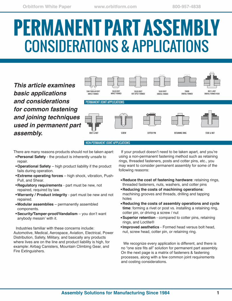
This article examines basic applications and considerations for common fastening and joining techniques used in permanent part assembly.
There are many reasons products should not be taken apart:•PersonalSafety - the product is inherently unsafe to repair.•OperationalSafety – high product liability if the product fails during operation.•Extremeoperatingforces– high shock, vibration, Push-Pull, and Shear.•Regulatoryrequirements - part must be new, not repaired, required by law.•Warranty/Productintegrity - part must be new and not repaired.•Modularassemblies – permanently assembled components.•Security/Tamper-proof/Vandalism – you don’t want anybody messin’ with it.
Industries familiar with these concerns include: Automotive, Medical, Aerospace, Aviation, Electrical, Power Distribution, Safety, Military, and basically any products where lives are on the line and product liability is high, for example: Airbag Canisters, Mountain Climbing Gear, and Fire Extinguishers.
If your product doesn’t need to be taken apart, and you’re using a non-permanent fastening method such as retaining rings, threaded fasteners, posts and cotter pins, etc., you may want to consider permanent assembly for some of the following reasons:
•Reducethecostoffasteninghardware: retaining rings, threaded fasteners, nuts, washers, and cotter pins•Reducingthecostsofmachiningoperations: machining grooves and threads, drilling and tapping holes•Reducingthecostsofassemblyoperationsandcycletime: forming a rivet or post vs. installing a retaining ring, cotter pin, or driving a screw / nut•Superiorretention - compared to cotter pins, retaining rings, and Loctite® •Improvedaesthetics - Formed head versus bolt head, nut, screw head, cotter pin, or retaining ring.
We recognize every application is different, and there is no “one size fits all” solution for permanent part assembly. On the next page is a matrix of fasteners & fastening processes, along with a few common joint requirements and costing considerations.
OrbitformWhitePaper 800-957-4838www.orbitform.com
AssemblySolutionsforManufacturingSince1984
FASTENER /PROCESS
KEY:
ARTICULATING
COMPRESSION(CLAMP LOAD)
LOW PROFILE
SHOCK VIBRATIONRESISTANT
HOLE FILL
AESTHETICS
FASTENER COST
MACHINING COST
EQUIPMENT COST
ASSEMBLYLABOR COST
OVERALL COSTN
ON
-PER
MA
NA
NT
PERM
AN
AN
TJOINT CHARACTERISTIC COSTING
TENONORBITAL/SPIRAL
TENON HOT UPSET
SOLID RIVET IMPACT
SEMI-TUBULARRIVET IMPACTRIVET ORBITAL/SPIRAL
RIVET HOT UPSET
BOLT/NUTFORMED
BOLT/NUT
STUD/NUT
SCREW
RETAINING RING
COTTER PIN
POOR FAIR GOOD BEST
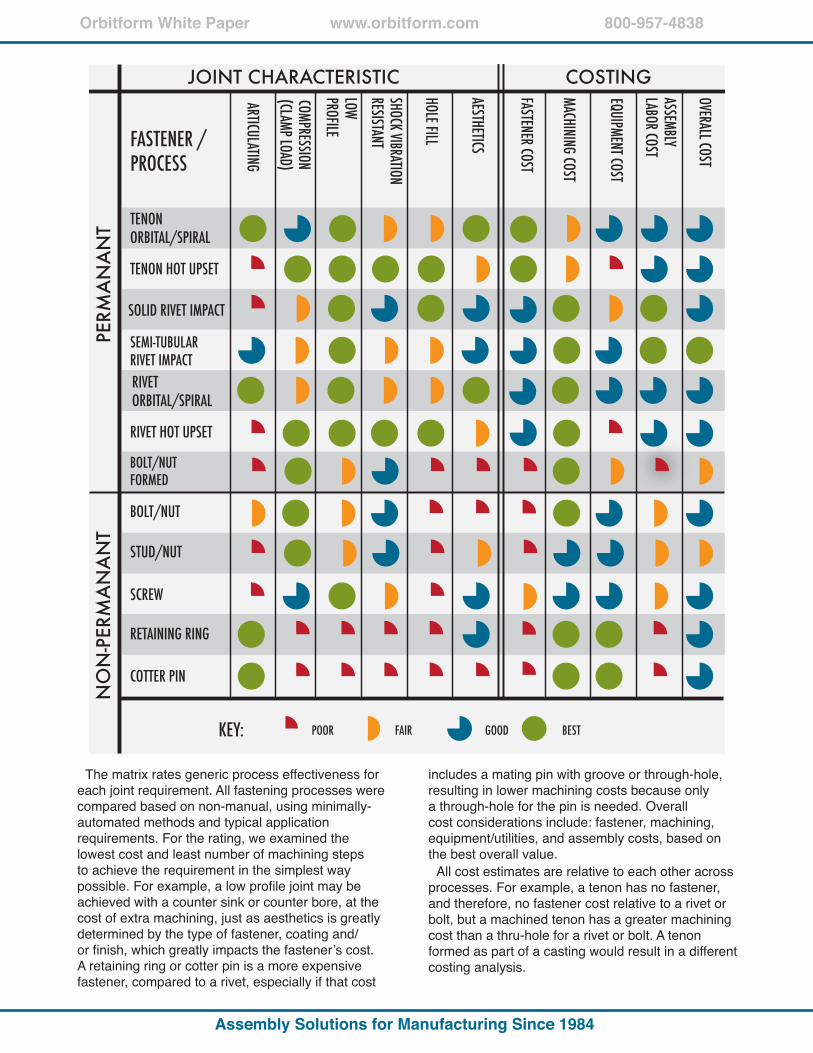
The matrix rates generic process effectiveness for each joint requirement. All fastening processes were compared based on non-manual, using minimally-automated methods and typical application requirements. For the rating, we examined the lowest cost and least number of machining steps to achieve the requirement in the simplest way possible. For example, a low profile joint may be achieved with a counter sink or counter bore, at the cost of extra machining, just as aesthetics is greatly determined by the type of fastener, coating and/or finish, which greatly impacts the fastener’s cost. A retaining ring or cotter pin is a more expensive fastener, compared to a rivet, especially if that cost
includes a mating pin with groove or through-hole, resulting in lower machining costs because only a through-hole for the pin is needed. Overall cost considerations include: fastener, machining, equipment/utilities, and assembly costs, based on the best overall value.
All cost estimates are relative to each other across processes. For example, a tenon has no fastener, and therefore, no fastener cost relative to a rivet or bolt, but a machined tenon has a greater machining cost than a thru-hole for a rivet or bolt. A tenon formed as part of a casting would result in a different costing analysis.
Orbitform White Paper
3
800-957-4838www.orbitform.com
Assembly Solutions for Manufacturing Since 1984
FIXTURE FIXTURE
PART SUPPORTED
GAP GAP
HEAD SUPPORTED
an anti-rotate device, an offset orbital head, and/or a modified peen with anti-rotate device. In addition, orbital heads can be configured to form multiple rivets simultaneously, using multi-spindle or multi-point tooling heads.
Clamp loading will vary based on forming a tenon or rivet, the type of material, tooling, and fixturing used. For example, If the part is supported (fig. 1.2), allowing a gap between the manufactured rivet head and the part, the final joint will allow the rivet to float and will not provide any compressive loading. If the manufactured rivet head is supported
FIG 1.2 FIG 1.3
(fig. 1.3), eliminating the gap between the part and the rivet, the joint will exhibit compressive loading. To improve clamp loading options include: a pressure pad to pre-clamp the part, increasing the advance rate of the Powerhead, and/or using an orbital head with a reduced attack angle to increase downward force.
Both Orbital and Spiral processes are recommended for low profile joints requiring articulation, because they form the rivet head without completely collapsing the shank. Clamp load can be adjusted to maintain some rotational torque/friction, as required in applications such as surgical scissors. Retaining rings and cotter pins allow articulation, but do not provide compressive loading characteristics, and therefore allow vibration between the fastener and the parts.
If the joint requires superior clamp loading and torque control, one fastening option is to use a bolt and nut, and then orbitally form the bolt against the face of the nut, locking the nut in place. Another option is to orbitally ring-stake the nut into the bolt’s threads to permanently lock them together. This additional operation adds to the production cost and reduces throughput. As a permanent solution, this is only recommended when extreme clamp loading and precise torque control is needed.
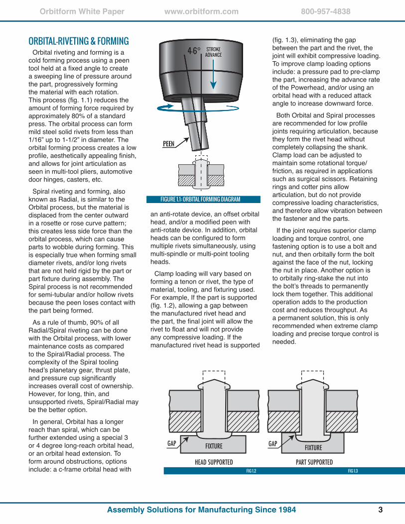
ORbITAL-RIvETING & FORMINGOrbital riveting and forming is a
cold forming process using a peen tool held at a fixed angle to create a sweeping line of pressure around the part, progressively forming the material with each rotation. This process (fig. 1.1) reduces the amount of forming force required by approximately 80% of a standard press. The orbital process can form mild steel solid rivets from less than 1/16” up to 1-1/2” in diameter. The orbital forming process creates a low profile, aesthetically appealing finish, and allows for joint articulation as seen in multi-tool pliers, automotive door hinges, casters, etc.
Spiral riveting and forming, also known as Radial, is similar to the Orbital process, but the material is displaced from the center outward in a rosette or rose curve pattern; this creates less side force than the orbital process, which can cause parts to wobble during forming. This is especially true when forming small diameter rivets, and/or long rivets that are not held rigid by the part or part fixture during assembly. The Spiral process is not recommended for semi-tubular and/or hollow rivets because the peen loses contact with the part being formed.
As a rule of thumb, 90% of all Radial/Spiral riveting can be done with the Orbital process, with lower maintenance costs as compared to the Spiral/Radial process. The complexity of the Spiral tooling head’s planetary gear, thrust plate, and pressure cup significantly increases overall cost of ownership. However, for long, thin, and unsupported rivets, Spiral/Radial may be the better option.
In general, Orbital has a longer reach than spiral, which can be further extended using a special 3 or 4 degree long-reach orbital head, or an orbital head extension. To form around obstructions, options include: a c-frame orbital head with
FIGURE 1.1: ORbITAL FORMING DIAGRAM
Orbitform White Paper
4
800-957-4838www.orbitform.com
Assembly Solutions for Manufacturing Since 1984
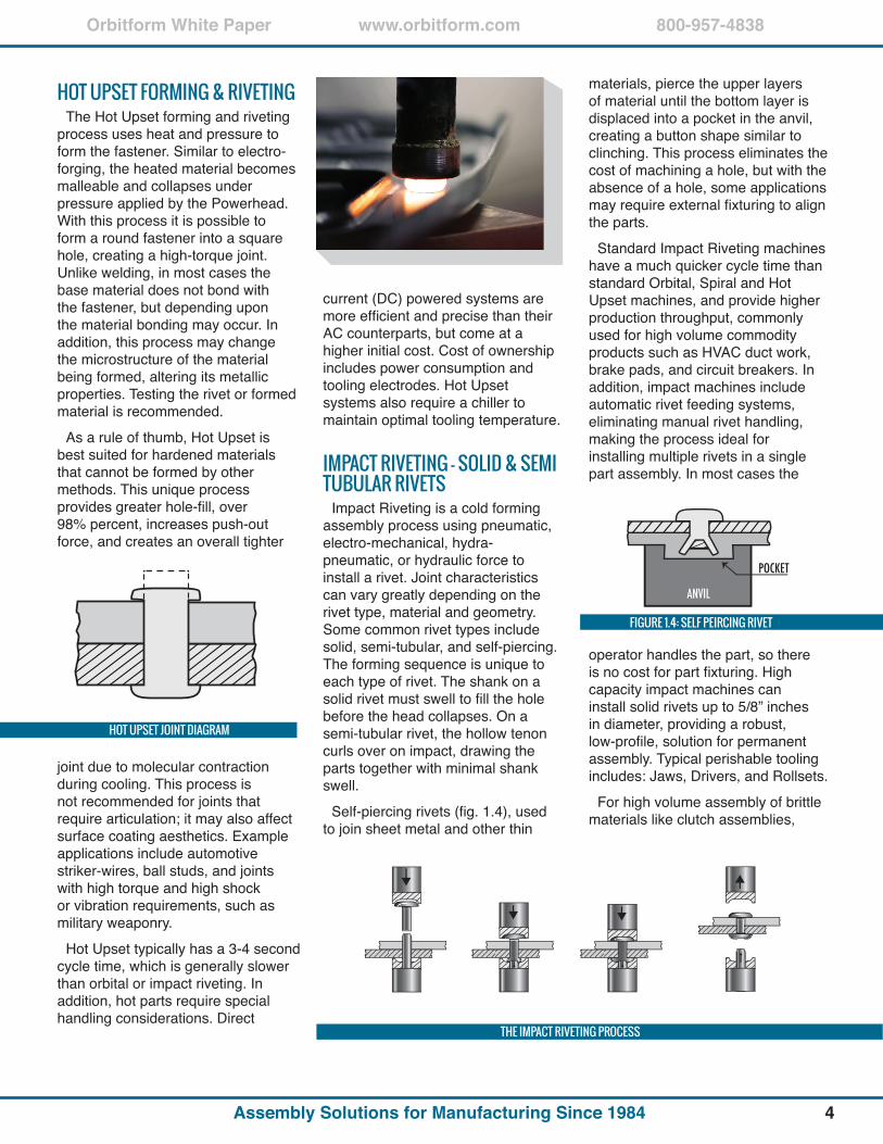
HOT UPSET FORMING & RIvETINGThe Hot Upset forming and riveting
process uses heat and pressure to form the fastener. Similar to electro-forging, the heated material becomes malleable and collapses under pressure applied by the Powerhead. With this process it is possible to form a round fastener into a square hole, creating a high-torque joint. Unlike welding, in most cases the base material does not bond with the fastener, but depending upon the material bonding may occur. In addition, this process may change the microstructure of the material being formed, altering its metallic properties. Testing the rivet or formed material is recommended.
As a rule of thumb, Hot Upset is best suited for hardened materials that cannot be formed by other methods. This unique process provides greater hole-fill, over 98% percent, increases push-out force, and creates an overall tighter
current (DC) powered systems are more efficient and precise than their AC counterparts, but come at a higher initial cost. Cost of ownership includes power consumption and tooling electrodes. Hot Upset systems also require a chiller to maintain optimal tooling temperature.
IMPACT RIvETING - SOLID & SEMI TUbULAR RIvETS
Impact Riveting is a cold forming assembly process using pneumatic, electro-mechanical, hydra-pneumatic, or hydraulic force to install a rivet. Joint characteristics can vary greatly depending on the rivet type, material and geometry. Some common rivet types include solid, semi-tubular, and self-piercing. The forming sequence is unique to each type of rivet. The shank on a solid rivet must swell to fill the hole before the head collapses. On a semi-tubular rivet, the hollow tenon curls over on impact, drawing the parts together with minimal shank swell.
Self-piercing rivets (fig. 1.4), used to join sheet metal and other thin
THE IMPACT RIvETING PROCESS
HOT UPSET JOINT DIAGRAM
FIGURE 1.4: SELF PEIRCING RIvET
materials, pierce the upper layers of material until the bottom layer is displaced into a pocket in the anvil, creating a button shape similar to clinching. This process eliminates the cost of machining a hole, but with the absence of a hole, some applications may require external fixturing to align the parts.
Standard Impact Riveting machines have a much quicker cycle time than standard Orbital, Spiral and Hot Upset machines, and provide higher production throughput, commonly used for high volume commodity products such as HVAC duct work, brake pads, and circuit breakers. In addition, impact machines include automatic rivet feeding systems, eliminating manual rivet handling, making the process ideal for installing multiple rivets in a single part assembly. In most cases the
joint due to molecular contraction during cooling. This process is not recommended for joints that require articulation; it may also affect surface coating aesthetics. Example applications include automotive striker-wires, ball studs, and joints with high torque and high shock or vibration requirements, such as military weaponry.
Hot Upset typically has a 3-4 second cycle time, which is generally slower than orbital or impact riveting. In addition, hot parts require special handling considerations. Direct
operator handles the part, so there is no cost for part fixturing. High capacity impact machines can install solid rivets up to 5/8” inches in diameter, providing a robust, low-profile, solution for permanent assembly. Typical perishable tooling includes: Jaws, Drivers, and Rollsets.
For high volume assembly of brittle materials like clutch assemblies,
Orbitform White Paper
5
800-957-4838www.orbitform.com
Assembly Solutions for Manufacturing Since 1984
circuit boards and plastics, riveting machines can be configured with load-deflecting components. To consolidate equipment and reduce the work area footprint, a single machine can be configured to install up to four rivets simultaneously; other options for multi-riveting include dual head and multi-head machines. Using an offset driver accessory, riveting heads can be positioned as close as 1/16” of an inch between rivet heads.
ROLLER FORMING - ASSEMbLING CYLINDRICAL PARTS
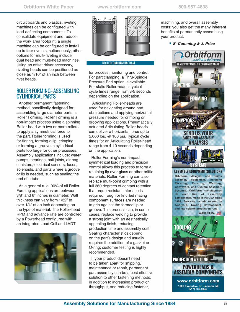
Another permanent fastening method, specifically designed for assembling large diameter parts, is Roller Forming. Roller Forming is a non-impact process using a spinning Roller-head with two or more rollers to apply a symmetrical force to the part. Roller forming is used for flaring, forming a lip, crimping, or forming a groove in cylindrical parts too large for other processes. Assembly applications include: water pumps, bearings, ball joints, air bag canisters, electrical sensors, fuses, solenoids, and parts where a groove or lip is needed, such as sealing the end of a tube.
As a general rule, 90% of all Roller Forming applications are between 3/8” and 6” inches in diameter. Wall thickness can vary from 1/32” to over 1/4” of an inch depending on the type of material. The Roller-head RPM and advance rate are controlled by a Powerhead configured with an integrated Load Cell and LVDT
for process monitoring and control. For part clamping, a Thru-Spindle Pressure Pad option is available. For static Roller-heads, typical cycle times range from 3-5 seconds depending on the application.
Articulating Roller-heads are used for navigating around part obstructions and applying horizontal pressure needed for crimping or grooving applications. Pneumatically actuated Articulating Roller-heads can deliver a horizontal force up to 5,000 lbs. @ 100 psi. Typical cycle times for an Articulating Roller-head range from 4-10 seconds depending on the application.
Roller Forming’s non-impact symmetrical loading and precision control allows this process to form a retaining lip over glass or other brittle materials. Roller Forming can also replace multi-point crimping with a full 360 degrees of contact retention. If a torque resistant interface is required, rough or knurled mating component surfaces are needed to grip against the formed lip or groove. This process can, in some cases, replace welding to provide a strong joint with an aesthetically appealing finish, reducing production time and assembly cost. Sealing characteristics depend on the part’s design and usually requires the addition of a gasket or O-ring; customer testing is highly recommended.
If your product doesn’t need to be taken apart for shipping, maintenance or repair, permanent part assembly can be a cost effective solution to other fastening methods, in addition to increasing production throughput, and reducing fastener,
machining, and overall assembly costs; you also get the many inherent benefits of permanently assembling your product.
S. Cumming & J. Price
PROJECTION WELDING
TOOLING
POWERHEADS &ASSEMBLY COMPONENTS
IT ALL STARTS WITH THE CUSTOMER’S PART
RIVETING
FORMING
www.orbitform.com1600 Executive Dr, Jackson, MI
(517) 787-9447
CONVEYORS
Orbitform designs and builds assembly equipment, including Riveting, Forming, Welding, Conveyors, and Custom Assembly Systems. Orbitform manufactures its own line of assembly components, made in the USA since 1984. Services include Assembly Analysis, Tooling Development, and low-volume production runs.
AS S E M B LY E Q U I P M E N T S O L U T I O N S
SYSTEMS
MADE IN THE USA
ROLLERFORMING DIAGRAM