
Peripheral modules on CIB Common Installation Bus® · PDF filePeripheral modules on CIB...
183
. PROGRAMOVATELN É AUTOMATY Peripheral modules on CIB Common Installation Bus® TXV 004 13.02
Transcript of Peripheral modules on CIB Common Installation Bus® · PDF filePeripheral modules on CIB...
.
PROGRAMOVATELNÉ AUTOMATY
Peripheral modules on CIB Common Installation Bus®
TXV 004 13.02

CONTENT
TXV 004 13.02 2
Peripheral modules on CIB bus
TXV 004 13.02
1. edition - January 2014
CONTENT 1. INTRODUCTION ................................................................................................................................................. 3
1.1. CIB - COMMON INSTALLATION BUS ......................................................................................................................... 3
2. CIB MASTER ....................................................................................................................................................... 3
2.1. MASTER CONFIGURATION ....................................................................................................................................... 9 2.2. THE STRUCTURE OF THE TRANSMITTED DATA ............................................................................................................ 12 2.3. POWER CIB BUS ................................................................................................................................................. 14
3. CIB UNITS, MODULES........................................................................................................................................17
3.1. C-AM-0600I .................................................................................................................................................... 18 3.2. C-AQ-0001R ................................................................................................................................................... 23 3.3. C-AQ-0002R ................................................................................................................................................... 26 3.4. C-AQ-0003R ................................................................................................................................................... 29 3.5. C-AQ-0004R ................................................................................................................................................... 31 3.6. C-DL-0012S .................................................................................................................................................... 33 3.7. C-DL-0064M ................................................................................................................................................... 37 3.8. C-DM-0006M-ILED ......................................................................................................................................... 41 3.9. C-DM-0006M-ULED ....................................................................................................................................... 45 3.10. C-DM-0402M-RLC .......................................................................................................................................... 48 3.11. C-HC-0201F-E ................................................................................................................................................. 57 3.12. C-HM-0308M ................................................................................................................................................. 64 3.13. C-HM-1113M ................................................................................................................................................. 69 3.14. C-HM-1121M ................................................................................................................................................. 74 3.15. C-IB-1800M .................................................................................................................................................... 79 3.16. C-IR-0202S ..................................................................................................................................................... 85 3.17. C-IR-0203M .................................................................................................................................................... 91 3.18. C-IT-0100H-A ................................................................................................................................................. 98 3.19. C-IT-0100H-P ................................................................................................................................................ 101 3.20. C-IT-0200I .................................................................................................................................................... 104 3.21. C-IT-0200R ................................................................................................................................................... 108 3.22. C-IT-0200S .................................................................................................................................................... 111 3.23. C-IT-0504S .................................................................................................................................................... 116 3.24. C-IT-0908S .................................................................................................................................................... 122 3.25. C-OR-0008M ................................................................................................................................................ 128 3.26. C-OR-0202B ................................................................................................................................................. 131 3.27. C-RC-0002R .................................................................................................................................................. 135 3.28. C-RC-0003R .................................................................................................................................................. 139 3.29. C-RI-0401S ................................................................................................................................................... 146 3.30. C-WG-0503S ................................................................................................................................................. 152 3.31. C-WS-0200R ................................................................................................................................................. 158 3.32. C-WS-0400R ................................................................................................................................................. 161 3.33. C-WS-0200R-LOGUS ...................................................................................................................................... 164 3.34. C-WS-0400R-LOGUS ...................................................................................................................................... 170 3.35. RCM2-1 ........................................................................................................................................................ 176
4. ATTACHMENTS ............................................................................................................................................... 180

1.1. CIB - Common Installation Bus
3 TXV 004 13.02 .
1. INTRODUCTION
The manual is intended to inform the user of PLC Tecomat Foxtrot with modules working on the CIB bus. It provides information about the basic parameters of modules and their operation.CIB, including their individual elements, is referred under the trademark CFox.
1.1. CIB - Common Installation Bus
CIB - Common Installation Bus is two wire installation bus. CIB modules are both powered and communicated over this two-wire bus.
The CIB bus has always one control master and up to 32 slave modules (units). Master can be an internal part of the central module or can be as expansion unit on the DIN rail in the control panel. CIB peripheral modules are delivered in several form factors - for interior installations as well as for DIN rail installation
Tab. 1.1 Basic parameters of the CIB bus
Number of wires*) 2
Cross-section of wires *) min. 0.8 mm2
Topology*) Arbitrary
Distance of the master from CIB slave module
max. 500m
Typical Voltage 24V DC (no backup) 27.2V DC (backup)
Tolerance of the supply voltage 20.4 ÷ 30V
The baud rate 19,2 kb/s *) It is recommended for CIB installation to use the twisted pair cable with the wire cross
section at least 0,8 mm2, e.g.. J-Y(St)Y1x2x0,8. The cross section and topology is necessary to choose with respect to the voltage drop along the cable - according to amount and type of CIB modules. For more details and CIB application examples see. Příručka projektanta systemů
Foxtrot (TXV 004 11). NOTE : With respect with CIB bus the term CIB peripheral module is equal with the
term CIB peripheral unit.
2. CIB MASTER
CIB master communicates with CIB peripheral modules and transfers the data into the central module over the system bus TCL2. The CIB master is available in two versions. As the internal master or as external master. Internal master is inherent part of the central modules Tecomat Foxtrot (CP-10xx), where it is referred as module CF-1140, (or MI2-01M). External master is connected to the Foxtrot over the system communication bus TCL2 and is referred as module CF-1141, (or MI2-02M).

CIB MASTER
TXV 004 13.02 4
Internal master contain 1 CIB branch (for up to 32 CIB slave modules), internal master of CP-1000/1001 and external master contains 2 CIB branches (2x up to 32 CIB slave modules). Beside to internal CIB master CPU Tecomat Foxtrot enables to serve up to 4 external CIB masters.
Since 2011 the family of CPU Tecomat Foxtrot are modernized. From the point of view of the CIB buses the modernization brings replacement of the former MI2-01M a MI2-02M masters by the new one with the names CF-1140 and CF-1141 (for comparison see more below).
Fig. 2.1 Front view CF-1141
Tab. 2.2 Basic parameters of CF-1141 module
CF-1141
System bus TCL2
The installation bus 2x CIB (2x up to 32 modules)
Load of CIB line max. 1A (for each CIB line)
Nominal Input Voltage 24V and 27.2V DC
Tolerance of the input voltage 20.4 ... 30V DC
Backup accumulator voltage 24V DC
Max. Load 60W
Self consumption 24mA
Dimensions 52 x 100 x 60mm
Weight 120g
Operating temperature 0 .. +70°C
Storage temperature -25 .. +85°C
Operation position arbitrary
Type of operation continuous
Installation on DIN rail
Connecting Removable screw type terminal
Cross-section of wires max. 2.5mm2
Module CF-1141 provides a full internal power for CIB lines (it contain internal
decoupling element for load capacity of 1A). Module also allows connecting and charging the backup battery that can power both the CIB lines as well as the PLC central module

1.1. CIB - Common Installation Bus
5 TXV 004 13.02 .
(the output terminals BACKUP). For connection see following chapter Connection of the CIB line to the master.
Tab. 2.3 Connection of the CF-1141 terminals
Terminal Signal Description
A1 TCL2+ data signal of the system bus TCL2 A2 TCL2- data signal of the system bus TCL2 A3,A4,A6,A8 GND ground terminal A5
+27V power supply 24V DC (bus without back-up) 27.2V DC (bus with back-up)
A7 +24V power from the backup battery 24V DC A9 BU+ back-up power supply 24 / 27V DC (BACKUP) B1, B2 CIB1+ CIB line 1 B3, B4 CIB1- CIB line 1 B6, B7 CIB2+ CIB line 2 B8, B9 CIB2- CIB line 2
ADR
0
2
46
81012
14
Fig.2.2 Front view MI2-02M
Tab. 2.4 Basic parameters of MI2-02M
MI2-02M
System bus TCL2
The installation bus 2x CIB (2x up to 32 modules)
Nominal input voltage (SELV) / own consumption
24V a 27.2V DC / 25mA from the bus CIB
Tolerance of the input voltage 20.4 ... 30V DC
Max. load 2.5W
Galvanic isolation No
Dimensions 90 x 18 x 65mm
Weight 75g
Operating temperature -20 .. +55°C
Storage temperature -30 .. +70°C
Electrical strength according to EN 60950
Degree of protection IP 30
Overvoltage category III
Degree of pollution according EN 61131-2 2
Operating position arbitrary
Installation on DIN rail

CIB MASTER
TXV 004 13.02 6
Connecting screw type terminals
Cross-section of wires max. 2.5mm2
Module MI2-02M does not contain the decoupling element to power the CIB lines. Lines have to be supplied externally by using decoupling modules, see chap. 2.3 Supplying of the CIB bus.
Tab. 2.5 Connection of the MI2-02 terminals
Signal Description
TCL2+ data signal of the system bus TCL2 TCL2- data signal of the system bus TCL2 GND signal ground CIB1+ CIB line 1 CIB1- CIB line 1 CIB2+ CIB line 2 CIB2- CIB line 2
Connecting the internal master module to the PLC TECOMAT Foxtrot Connecting the internal master (CF-1140 or MI2-01M) is done by internal circuitry of
CPU without any additional outside interconnections.
Connecting the external master module to the PLC TECOMAT Foxtrot The external master (CF-1141 or MI2-02M) is connected to the PLC Foxtrot via the
interface circuits on terminals A1 to A3 marked as TC LINE.
TC
L2+A1 A5
TC
L2+
A4 A8 A9
PLC Tecomat Foxtrot MI2-02MCF-1141
Zakončovací člen KB-0290
GN
D
A3 A7
TC
L2
-A2 A6
TC
L2-
GN
D
Fig. 2.3 Connecting the external master module to the PLC TECOMAT Foxtrot
On the PLC side the communication line TCL2 is terminated inside the PLC module. On
the side of master module it is necessary to do the termination. This is achieved by using a terminating element KB-0290 (TXN 102 90) connected between the terminals TCL2+ and TCL2-.The terminator is a part of package PLC Foxtrot. If there are other modules the communication line TCL2, termination has to be placed at the end of the whole line!!

1.1. CIB - Common Installation Bus
7 TXV 004 13.02 .
Connecting CIB line to the master module
CIB line is connected to the master module via terminals + CIB and CIB-.If the CIB line has to be powered by an external power source, the power source must be separated from the CIB line by the decoupling module C-BS-0001 or BPS2-02M. Some CIB lines are fully (or partially) supplied directly from internal circuits of the master (see chap. 2.3 Supplying of the CIB bus).
A1 A2 A3 A4 A5 A6 A7 A8 A9
GN
D
TC
L2+
TC
L2-
GN
D
+2
4V
GN
D
+2
7V
GN
D
UB
+
POWER 27V=TC LINE
BACKUPACU 24V=
CIB
1+
CIB
2-
CIB
1-
CIB
2-
CIB
1-
CIB
2+
CIB
1+
CIB
2+
CI BUS1 CI BUS2
B1 B2 B3 B4 B5 B6 B7 B8 B9
CF-1141ADR
14
1210
6420
8
PWR2 CIB2PWR1 CIB1
PWR ACU BU
CIB1
CIB 2
POWER 27,2V = ACU 24V =
BPS2-02M
CIB
2-
CIB
2+
CIB
1-
CIB
1+
+2
7V
GN
D
+2
7V
GN
D
+ - + -
input 27 VDC Battery 24 V
CIB2CIB1Out 27 VDC
VOUT 27 VDC CIB1 CIB2
VIN 27 VDC Batt 24 VDC
CIB1
CIB2
ZÁLOŽNÍ AKUMULÁTOR 24 V
NAPÁJENÍ 27,2 VDC
ADR
0
2
46
81012
14
CIB
2+
CIB
1+
TC
L2
+
CIB
2-
CIB
1-
TC
L2-
GN
D
MI2-02M
CIB
1
CIB
2
Fig.2.4 Connecting CF-1141 to CIB line Fig.2.5 Connecting MI2-02M to CIB line by BPS2-02M
A1 A2 A3 A4 A5 A6 A7 A8 A9 C1B1 C2B2 C3B3 C4B4 C5B5 C6B6 C7B7 C8B8 C9B9
D1 E1 F1D2 E2 F2D3 E3 F3D4 E4 F4D5 E5 F5D6 E6 F6D7 E7 F7D8 E8 F8D9 E9 F9
TC
L2
+
TC
L2-
GN
D
GN
D
CIB
1+
CIB
2-
CIB
2-
CIB
2+
CIB
2+
CIB
1-
CIB
1-
CIB
1+
TxD
RxD
RT
S
TC LINE CH1/RS-232
GN
DS
GN
DS
N NL LDO
0
CO
M2
CO
M1
DO
1
DIGITAL/ANALOG INPUTS HDOIN 230 VAC D. OUTPUTD. OUTPUT
AG
ND
GN
D
+24
V
+27
V
+27
V
+27
V
GN
D
GN
D
GN
D
DI3
DI2
DI1
DI0
CI BUS 2CI BUS 1 POWER 27 VDCACU 24 VDC
AI3
AI2
AI1
AI0
CH2 SUBMODULE (e.g. RS-232, RS-485)
RT
SB
T-
BT
+
+5 V
TxR
x-
TxR
x-
TxR
x+
TxR
x+
- ---+5 V
RxD
CT
S
TxD
CIB 2CIB 1 POWER 27,2V =ACU 24V =
Fig.2.6 Connecting of the basic module Foxtrot CP-1000 to the CIB line

CIB MASTER
TXV 004 13.02 8
CIB1
NAPÁJENÍ 24 VDC
+24V 0V
GN
DC
IB-
27 VDC
CIB
+2
7V
CIB
+
PWR
B1
A1
B3
A3
B2
A2
A1 A2 A3 A4 A5 A6 A7 A8 A9 B1 B2 B3 B4 B5 B6 B7 B8 B9
TC
L2+
TC
L2-
GN
D
+24
V
CIB
+
CIB
-
TxD
RxD
RT
S
TC LINE 24 V DC CIB LINE CH1/RS-232
GN
D
DI7
DI3
DI6
DI2
DI5
DI1
DI4
DI0
DIGITAL/ANALOG INPUTSDIGITAL INPUTS
AI3
AI2
AI1
AI0
GN
DS
GN
DS
CH2 SUBMODULE (e.g. RS-232, RS-485)
RT
SB
T-
BT
+
+5
V
TxR
x-
TxR
x-
TxR
x+
TxR
x+
- ---+5
V
RxD
CT
S
TxD
C1 C2 C3 C4 C5 C6 C7 C8 C9
CO
M1
CO
M2
DO
2
DO
5
DO
1
DO
4
DO
0
DO
3
DIGITAL OUTPUTS
D1 D2 D3 D4 D5 D6 D7 D8 D9
CP-1004
Fig. 2.7 Connecting of the basic module Foxtrot CP-1004 to the CIB line with C-BS-0001M
Communication parameters
Master module communicates with the CPU by system messages of the bus TCL2. Parameters of communication are fixed by the specification of the TCL2 bus.
In terms of addressing on the TCL2 the internal CIB master is firmly mapped in the frame number 0, slot 2
For CIB lines of external master its communication address is set by the rotary switch on the front cover of the module. By setting its address, the module is uniquely addressed on TCL2 bus. This addressing must be done with respect to the addresses of other participants TCL2 to avoid address collisions. So the external CIB master module (resp. its two CIB lines) will be mapped always in the frame 3. Address of the line CIB1 of respected master will be equal to the position of the rotary switch, address of the line CIB2 of the same master will equal to the position of rotary switch incremented by +1.
Indicators
For the internal master no indicators are on the front panel of CPU. On the front panel of external master there are two LED indicators(CIB1 a CIB2), each
for the signalisation of the traffic on respective CIB line. In case of still green light of LED the CIB is in HLAT mode. (No connected module is served). In case of blinking green light of LED, module is in RUN mode (slave modules are serviced) and all serviced slave modules communicates. Blinking red among the green blinking in RUN mode indicates the communication failure of some slave module on the line.

2.1. Master configuration
9 TXV 004 13.02 .
On the external master CF-1141 there are additional 5 LED indicators (PWR, ACU, BU, PWR1, PWR2) monitoring the voltage level of the individual sections of the master. In the normal state all 5 LED still light. In case of voltage drop below the 22V limit, corresponding LED will blink (or turns off completely). Limitations and comparison of master module MI2-01M with CF-1140 and MI2-02M with CF-1141
Modules MI2-01M and MI2-02M enables to serve up to 32 CIB slave modules on one
CIB line. Because of the limits of module memory, however there are some limitations in the real number of slave modules. In practice, there may be cases where these masters are actually able to serve fewer modules than the specified maximum value of 32 modules on one line CIB. These cases occur particularly in the cases where there is e.g. vast majority of the modules of the same type on one CIB line.
Modules CF-1140 and CF-1141 have much higher memory capacity, which enable to serve really32 slave modules on one CIB line.
Information about the used memory capacity of the specific CIB line can be seen on the bar graph in unit/device manager (see. fig. 2.9).
2.1. Master configuration
Adding new master in the PLC Tecomat Foxtrot configuration is done by dialog HW Configuration in Project Manager. CPU Tecomat Foxtrot allows handling one CIB line using the internal master (CF-1140, MI2-01M) and up to 8 external CIB lines using 4 external masters (both external masters CF-1141 and MI2-02M contain 2 CIB lines).
Activation of the operator's internal master is done in menu Central module.
Fig. 2.8 Activation of serving of the internal CIB master
Adding new external master in the PLC Tecomat Foxtrot configuration is done by the same dialog in menu External CIB .

CIB MASTER
TXV 004 13.02 10
Fig. 2.9 Activation of serving of the external CIB master
SW configuration of master to serve the modules on CIB bus is performed in dialog
Unit/device manager. Dialog is available in the window HW Configuration after the click on icon on the line of the master.
Fig. 2.10 SW configuration of the CIB master
CIB modules can be added on the list manually by the button Add the unit, or automatically by the button Read the configuration from CPU. Remove module by the button Delete unit. Removing all modules can be done by button Delete all. Then it shows

2.1. Master configuration
11 TXV 004 13.02 .
the option to remove all units from the actual CIB line, from the current CIB master or all units from all masters.
At the top of the window right next to the name of the line of selected CIB master is a colour bar graph indicating the usage of memory of the respective CIB lines. If the bar is green the memory capacity for the line is sufficient. If the bar changes the colour for yellow, the memory capacity is near to the limit. It is warning status. If the bar changes the colour for red, the memory capacity is overflow. In such case the line is not able to serve requirements of CIB modules on the line and some module has to be removed from CIB line.
Bar graphs next to the names of individual masters display only to the occupation of the CIB line, disregarding the memory capacity of the line (graph is still green).
HW address of CIB module Fix address is assigned to the module during the manufacturing process and is written
on the cover of the module. CIB address is 4-digit code in hexadecimal format. On the same CIB line cannot be more units with the same HW address!!!! HW address 0000 is dedicated one. (It is excluded from the CIB services).Assignment of the address 0000 is used for temporary withdrawal unit from service of CIB master (while the I/O unit variables stay kept in the structure of the master CIB).
Name of the module It is possible to enter user identification of the module. Entered text will be used as
prefix of the structured data of the module. Advanced settings For modules which allows extended user configuration button Advanced settings is
available. Press the button to activate the dialog offering other properties of the module. Naming / alias You can specify a symbolic name under which structure of inputs/outputs of the module
will be available in the user program and also in the visualization (SCADA) environment. Export for visualisation When checking the item - data structure will be included in the export public file used as
input file for visualization software. In terms of service each CIB module is divided into devices (input, output, digital,
analogue, ....) and the device is further divided into specific inputs / outputs (digital input, digital output, analog input, ....).
Show all devices of all modules Checking item the tree branch units of equipment will be unpacked. Checking box Use
device of the optional device enables to activate or deactivate it.

CIB MASTER
TXV 004 13.02 12
Base address of the zone Checking the item enables to enter the absolute position of the beginning of the CIB line
in the stack.
2.2. The structure of the transmitted data
CIB master reserves data area in the stack of CPU in which the data transmitted from/to, status and fault zone CIB modules are available. Structure of the data area is evident from panel Setting I/O in Mosaic environment. Panel is available after pressing icon in toolbar.
Fig. 2.11 The structure of the transmitted data
MIx_CIBx_IN_[ ], MIx_CIBx_OUT_[ ] Zone of input dataMIx_CIBx_IN_[] and zone of output data MIx_CIBx_OUT_[] is
structured into items IDx_IN and IDx_OUT in the same order as the CIB modules are inserted during the configuration of the CIB line.
2.2. The structure of the transmitted data
13 TXV 004 13.02 .
Data are available for the user program either under the automatically generated variable names (column Full entry), or under the user name assigned in the Unit/Device manager during configuration (column Alias).
Before transmission to/from the bus CIB some input/output data are automatically converted to/from other format for efficient transmission over the CIB bus, but in the stack they are accessible in the normal format.
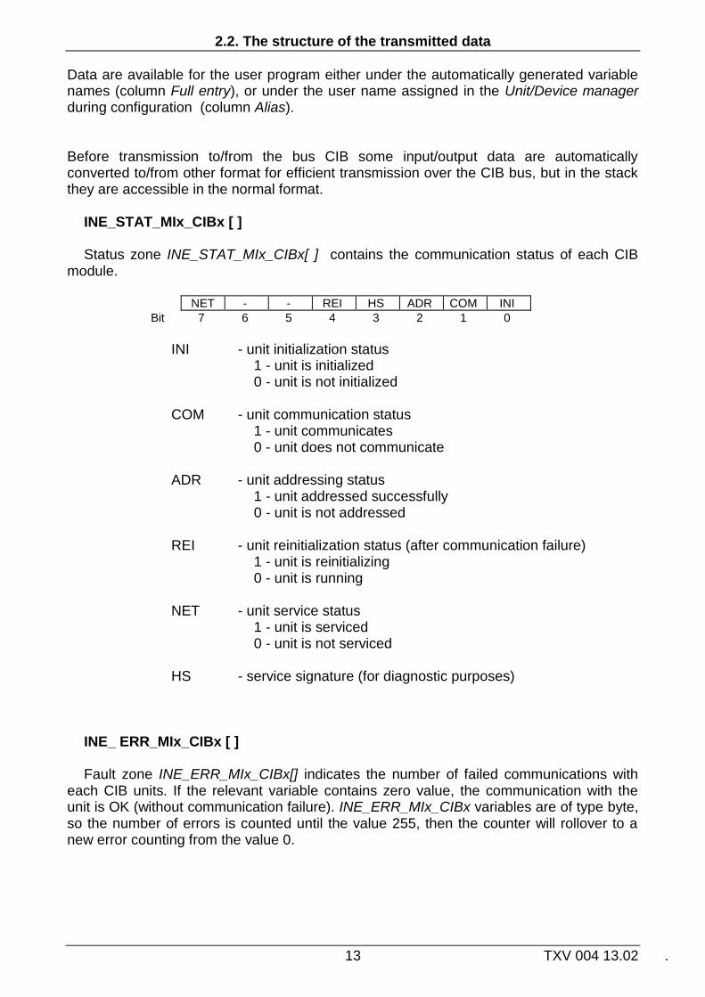
INE_STAT_MIx_CIBx [ ] Status zone INE_STAT_MIx_CIBx[ ] contains the communication status of each CIB
module.
NET - - REI HS ADR COM INI
Bit 7 6 5 4 3 2 1 0
INI - unit initialization status 1 - unit is initialized 0 - unit is not initialized
COM - unit communication status 1 - unit communicates 0 - unit does not communicate
ADR - unit addressing status 1 - unit addressed successfully 0 - unit is not addressed REI - unit reinitialization status (after communication failure) 1 - unit is reinitializing 0 - unit is running
NET - unit service status 1 - unit is serviced 0 - unit is not serviced
HS - service signature (for diagnostic purposes)
INE_ ERR_MIx_CIBx [ ] Fault zone INE_ERR_MIx_CIBx[] indicates the number of failed communications with
each CIB units. If the relevant variable contains zero value, the communication with the unit is OK (without communication failure). INE_ERR_MIx_CIBx variables are of type byte, so the number of errors is counted until the value 255, then the counter will rollover to a new error counting from the value 0.

CIB MASTER
TXV 004 13.02 14
2.3. Power CIB bus
CIB bus has to be powered for the proper operation. Bus power supply can be provided internally directly from CIB master modules, or external power supply is required (see next Tab. below).
For backup power of CIB bus the switching power supply is recommended:PS2-60/27 (27.2V DC, 60W, designed to recharge batteries). For not backup power of CIB buses it is possible to use switching power supply DR-60-24 (24V DC, 60W). In the case of external power CIB bus options for proper operation is always necessary so separate the impedance of the power supply from the CIB bus by decoupling module C-BS-0001M or BPS2-02M.I the case of internal power CIB bus (e.g. from CF-1141 master module, or from CP-1000/1001 basic module) it is not necessary any additional decoupling. Decoupling is provided directly by these modules.
Module C-BS-0001 provides decoupling of the power supply for one CIB line. Module BPS2-002M provides decoupling of the power supply for two CIB lines.
On the module there is also available direct output voltage to supply the CPU and its peripherals. The module also allows connecting and charging the backup battery that can power both the CPU and CIB lines in case of failure of main power line.
Tab. 2.6 Number of CIB lines in CPU Foxtrot and their power supply CP-1000
1
CP-1004 4
CP-1005 3
CP-1006 2
CP-1008 2
CP-1014
4
CP-1015 3
CP-1016 2
CP-1018 2
CP-1020 1
CP-1026 2
CP-1028 2
CP-1036 2
CP-1038 2
CIB Bus - internal lines
2
1
1
2
1
1
- more lines 5 by the external
modules MI2-02M
3 and CF-1141 1
8
1 Modules provide full internal power of CIB lines from the master (max. load 1A on each CIB line), external
power for CIB lines is not required. 2 Modules provide partial power CIB lines from internal master for load up to 100mA. For higher load it is
necessary to use additional power over the decoupling module. 3 Modules do not contain internal power supply of CIB lines. It is always necessary to use an external
power supply connected over the decoupling module. 4 Modules with internal master CF-1140 (models of year 2011 and later) include partial power lines from the
CIB Master for internal consumption up to 100mA. For higher loads is necessary to use an external power supply connected over decoupling module. Modules with internal master MI2-01M (models before year 2010) do not contain any internal power of CIB lines. It is always necessary to use an external power supply connected over the decoupling module.
5 The total number of connected CIB lines and RFox networks interact. Total number of modules CF-1141,
MI2-02M and RF-1131 can be max. 4.

2.3. Power CIB bus
15 TXV 004 13.02 .
Tab. 2.7 Basic parameters C-BS-0001M
+27V
GND
+CIB
-
vstupní napájení
GN
DC
IB-
27 VDC
CIB
+2
7V
CIB
+
PWR
B1
A1
B3
A3
B2
A2
Fig. 2.12 Connection example C-BS-0001M
Tab. 2.8 Basic parameters BPS2-02M
Fig. 2.13 Connection example of BPS2-02M
Power supply
Input voltage 24 ÷ 27,2V DC
Output voltage for CIB 1x 24 ÷ 27,2V DC / 1A
Dimensions and weight
Dimensions 90 × 18 × 60mm
Weight 120g
Operating and installation conditions
Operating temperature 0 ÷ +70 °C
Storage temperature –25 ÷ +85 °C
Electrical strength according to EN 60950
IP degree of protection acc. IEC 529
IP 20
Overvoltage category III
Degree of pollution according EN 61131-2
2
Operating position arbitrary
Installation on DIN rail
Connecting screw type terminals
Cross-section of wires max. 2,5 mm2
Power supply
Input voltage 24 ÷ 27,2V DC
Output voltage for CIB 2x 24 ÷ 27,2V DC / 1A
Output voltage CPU 24 ÷ 27,2V DC / 1A
Input for AKU 24V (2x 12V in series)
The charging current AKU
2A
Dimensions and weight
Dimensions 90 × 52 × 65mm
Weight 100g
Operating and installation conditions
Operating temperature –20 ÷ +55 °C
Storage temperature –30 ÷ +70 °C
Electrical strength according to EN 60950
IP degree of protection acc. IEC 529
IP 20
Overvoltage category III
Degree of pollution according EN 61131-2
2
Operating position arbitrary
Installation on DIN rail
Connecting screw type terminals
Cross-section of wires max. 2,5 mm2
CIB MASTER
TXV 004 13.02 16
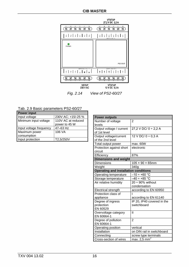
Fig. 2.14 View of PS2-60/27
Tab. 2.9 Basic parameters PS2-60/27 Power input
Input voltage 230V AC; +15/-25 %
Minimum input voltage 110V AC at reduced power to 45 W
Input voltage frequency 47–63 Hz
Maximum power consumption
106 VA
Input protection T2,5/250V
Power outputs
Number of voltage levels
2
Output voltage / current of 1st level
27,2 V DC/ 0 ÷ 2,2 A
Output voltage/current of the 2nd level
12 V DC/ 0 ÷ 0,3 A
Total output power max. 60W
Protection against short circuit
electronic
Efficiency 87%
Dimensions and weight
Dimensions 105 × 90 × 65mm
Weight 340g
Operating and installation conditions
Operating temperature –10 ÷ +60 °C
Storage temperature –40 ÷ +85 °C
Air relative humidity 20 ÷ 90% without condensation
Electrical strength according to EN 60950
Protection class of appliance
I according to EN 61140
Degree of ingress protection EN 60529
IP 20, IP40 covered in the switchboard
Overvoltage category EN 60664-1
II
Degree of pollution EN 60664-1
2
Operating position vertical
Installation on DIN rail in switchboard
Connecting screw type terminals
Cross-section of wires max. 2,5 mm2

2.3. Power CIB bus
17 TXV 004 13.02 .
3. CIB UNITS, MODULES
This chapter describes the parameters CIB units, examples of their connection, configuration procedure and description of the structures of data transmitted by units. Dialogs of unit configuration are available from the window Unit/device manager after pressing button Advanced settings.
Structures of transmitted data can be seen in the window I/O setting in Mosaic, see. fig. 2.4 Panel is available by clicking on the icon in the toolbar.
Structure items have assigned symbolic names that begin always by characters IDx_IN and IDx_OUT, where x is number corresponding to the order of unit on the bus (column ID in Unit/device manager). In the column Full notation is always present concrete symbolic name for that item. If we want to use data in the user program we use either this symbolic name or we enter our own symbolic name that can then be used into the column Alias. We do not use absolute operands in any case since they can be changed after next compilation of the user program.
CIB modules of INELS II manufactured by ELKO EP s.r.o. Holešov, that can be
connected to the CIB bus, are described in separate manual Peripheral modules INELS II on CIB bus (TXV 004 17).
ELKO EP, INELS and iNELS are registered trademarks of Elko EP s.r.o. Holešov.

CIB UNITS, MODULES
TXV 004 13.02 18
3.1. C-AM-0600I
Measuring module contains five universal inputs and 1 interface for connecting the flow meter Taconova AV23. Universal inputs can be configured for measuring resistive temperature sensors, voltage and current or as binary inputs or as an input interface for counting pulses from energy meters (standard interface S0 according to IEC 61393 / DIN 43864). Interface for connecting a flow meter Taconova AV23 includes two measuring inputs, one for the evaluation of the flow and one for evaluating the temperature of the reference medium.
The module is housed in a plastic box with increased protection IP55, for installation on the wall or on the cover of the device or panel.
Under the plastic cover of the module is placed LED indicator. After connecting the module to the CIB line (power connected) the green RUN LED lights still. If the module is served by the CIB (it communicates), green RUN LED flashes regularly.

3.1. C-AM-0600I
19 TXV 004 13.02 .
Tab. 3.1 Basic parameters C-AM-0600I
Fig. 3. 1 View and connecting C-AM-0600I
Interface for flow meter Taconova AV23
Supply voltage 5V DC
Typical power consumption from CIB
3mA
Input resistance >14kΩ
Range of measurement
0.5 ÷ 3.5V ~ 1 ÷ 12 l/min, ~ 2 ÷ 40 l/min, ~ 0 ÷ 100 °C
Measurement error ±0.5%
Power supply
Power supply and communication
24 V (27 V) from the CIB
Max. power consumption
80mA
Dimensions and weight
Dimensions 104 × 85 × 37mm
Weight 65 g
1) For resistors over 50kΩ the resolution of AD converter decreases considerably thus increasing measurement error. These ranges
are only complementary. 2) Range OV450k can only be set on input AI5.
3) Binary inputs do not have their own configuration dialog. They are set by the configuration dialog of the corresponding analog input.
4) Active binary input corresponds to the range of 0 ÷ 10V. Passive binary input corresponds to ranges Pt1000, Ni1000, KTY81-121.
5) Input AI5 as pulse counter has to use reduced voltage that does not meet the standard interface S0. 3.1.1. Configuration
Universal inputs
Quantity 5
Optional input type analog, binary, pulse counter
- Analog
Resistance ranges Pt1000 (–90 ÷ +320 °C), Ni1000 (–60 ÷ +200 °C), NTC12k (–40 ÷ +125 °C), KTY81-121 (–55 ÷ +125°C) OV200k (0 ÷ 200kΩ), OV450k (0 ÷ 450kΩ)
Voltage ranges 0 ÷ 10V, 0 ÷ 2V, 0 ÷ 1V
Current ranges 0 ÷ 20mA, 4 ÷ 20mA
Accuracy ±0.5% of full range, ±1% (NTC12k), ±10% (OV200k,OV450k)
1)2)
Period of refresh AI typically 5s
- Binary3)
Delay log.0 -> log.1 10ms
Delay log.1 -> log.0 500ms
Minimal pulse width 30ms
Type of binary input4)
Active or passive
- Passive Input voltage
7.4V from internal power supply
- Active Input resistance
64.9kΩ
- Pulse counter (standard interface S0, IEC 61393)
Reference voltage typ. 24V DC for AI1 ÷AI4, 7.4V for AI5
5)
Max. input current 14mA
Min. pulse width 30ms
Max. pulse frequency 20Hz
Max. switch resistance 800Ω in closed state
Operating and installation conditions
Operating temperature -10 ÷ +55 °C
Storage temperature -25 ÷ +70 °C
IP degree of protection acc. IEC 529
IP55
Operating position arbitrary
Type of operation continuous
Installation
Type wall (surface) mounting
Connecting Push-in terminals, AV23 connector
Cross-section of wires 0.14 ÷ 1.5 mm2

CIB UNITS, MODULES
TXV 004 13.02 20
Fig. 3.2 Module configuration
Input terminals of the module are shared, for more functions of inputs (devices). Depending on the configured input (as enabled devices) specific items of configuration dialog are enabled/disabled. Enabling devices see. chap.2.1 Master configuration, check the box Show units, devices
Type of input Choosing the type of analog input:
Pt1000, W100 = 1,385, -90/+320°C Pt1000, W100 = 1,391, -90/+320°C Ni1000, W100 = 1,617, -60/+200°C Ni1000, W100 = 1,500, -60/+200°C
NTC 12k (negative thermistor, 12k at 25°C), -40/+125°C KTY 81-121, -55/+125°C 0 ÷ 10V 0 ÷ 2V 0 ÷ 1V 0 ÷ 20mA 4 ÷ 20mA OV200k (0 ÷ 200kΩ) OV450k (0 ÷ 450kΩ) 16-bit pulse counter, S0
Input filtering By specifying a non-zero value of the time constant, the 1st order digital filter is
activated. The filter is given by
1
1
xyy t
t

3.1. C-AM-0600I
21 TXV 004 13.02 .
x - the current value of the analog input yt - output yt-1 - recent output time constant of the 1st order filter (TAU) - ح
Value of time constant is set in the range 0.1 ÷ 25.4 and it represents a time constant in the range of 100 ms ÷ 25.4 s (value 255 is intended for service purposes).
Range of flow meter Range selection of the connected flowmeter Taconova AV23:
1 ÷ 12 l/min 2 ÷ 40 l/min
Measurements format Choosing the format in which the data from the flow meter Taconova AV23 will be
presented: l/min m3/h dm3/h
3.1.1. The structure of the transmitted data
The module contains a total of six devices, each of them can be individually activated / deactivated
- device 1, input, 1*STAT (status of analog AI)
- device 2, input, 2*AI (input AI1, AI2)
- device 3, input, 2*AI (input AI3, AI4)
- device 4, input, 1*AI (input AI5)
- device 5, input, 2*AI (flow meter AV23)
- device 6, input, 5*DI (binary inputs)
The devices are incorporated into the structure of the transmitted data, which is evident
from window I/O setting in the Mosaic. Window is accessible by pressing the icon in toolbar.

CIB UNITS, MODULES
TXV 004 13.02 22
Fig. 3.3 The structure of the transmitted data
Input data
STAT AI1 AI2 AI3 AI4 AI5 AV23 DI
STAT - status byte of analog inputs (16x type bool)
VLD4 OUF4 VLD3 OUF3 VLD2 OUF2 VLD1 OUF1
Bit .7 .6 .5 .4 .3 .2 .1 .0
- - VLD6b OUF6b VLD6a OUF6a VLD5 OUF5
Bit .15 .14 .13 .12 .11 .10 .9 .8
OUFx - overflow / underflow of analog input AIx VLDx - validity of reading of analog input AIx OUF6a - overflow / underflow of range of flow meter FLOW VLD6a - validity of reading the flow meter FLOW OUF6b - overflow / underflow of range of thermometer THERM VLD6b - validity of reading the thermometer THERM AIx - value of analog input AIx, number of pulses of counter (type real) [°C],
[kΩ], [mV], [mA], [pulses]
AV23.FLOW - media flow of flow meter AV23 (type real) [l/min, m3/h, dm3/h] AV23.THERM - media temperature of flow meter AV23 (type real) [°C]
DI - status of binary inputs (8x type bool)
- - - DI5 DI4 DI3 DI2 DI1
Bit .7 .6 .5 .4 .3 .2 .1 .0
DIx - status of binary input DIx
3.2. C-AQ-0001R
23 TXV 004 13.02 .
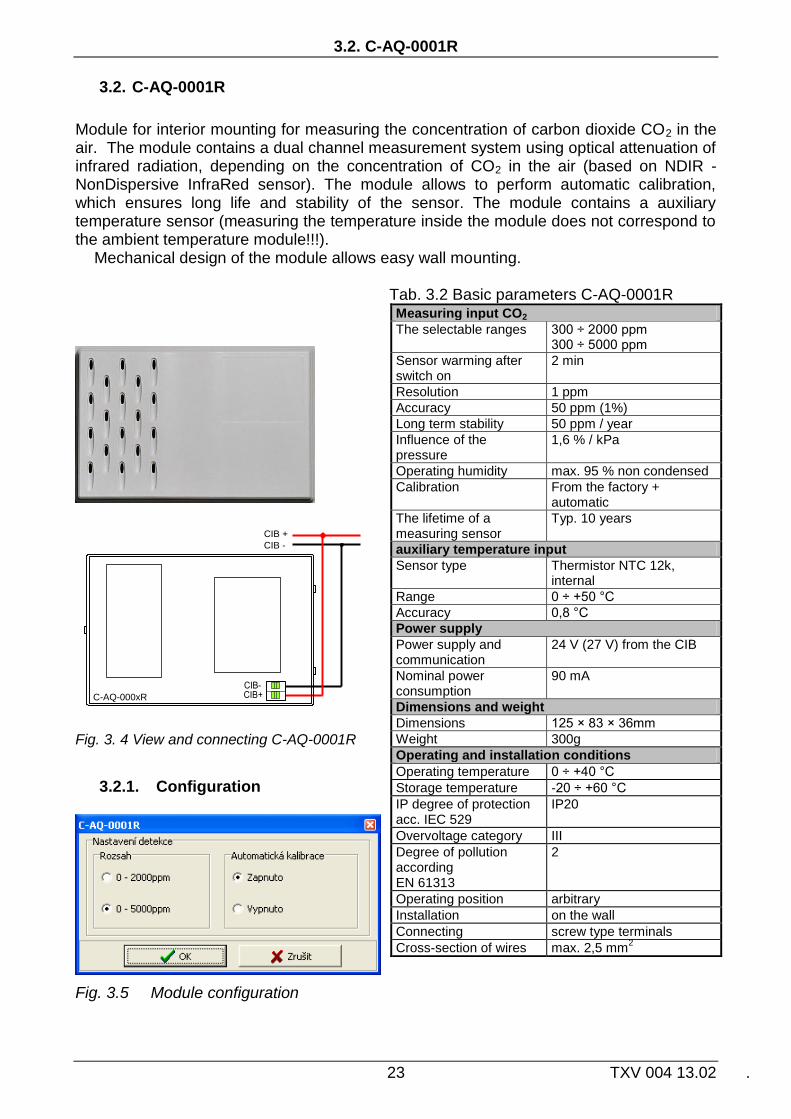
3.2. C-AQ-0001R
Module for interior mounting for measuring the concentration of carbon dioxide CO2 in the air. The module contains a dual channel measurement system using optical attenuation of infrared radiation, depending on the concentration of CO2 in the air (based on NDIR - NonDispersive InfraRed sensor). The module allows to perform automatic calibration, which ensures long life and stability of the sensor. The module contains a auxiliary temperature sensor (measuring the temperature inside the module does not correspond to the ambient temperature module!!!).
Mechanical design of the module allows easy wall mounting. Tab. 3.2 Basic parameters C-AQ-0001R
C-AQ-000xR
CIB +
CIB -
Fig. 3. 4 View and connecting C-AQ-0001R
3.2.1. Configuration
Fig. 3.5 Module configuration
Measuring input CO2
The selectable ranges 300 ÷ 2000 ppm 300 ÷ 5000 ppm
Sensor warming after switch on
2 min
Resolution 1 ppm
Accuracy 50 ppm (1%)
Long term stability 50 ppm / year
Influence of the pressure
1,6 % / kPa
Operating humidity max. 95 % non condensed
Calibration From the factory + automatic
The lifetime of a measuring sensor
Typ. 10 years
auxiliary temperature input
Sensor type Thermistor NTC 12k, internal
Range 0 ÷ +50 °C
Accuracy 0,8 °C
Power supply
Power supply and communication
24 V (27 V) from the CIB
Nominal power consumption
90 mA
Dimensions and weight
Dimensions 125 × 83 × 36mm
Weight 300g
Operating and installation conditions
Operating temperature 0 ÷ +40 °C
Storage temperature -20 ÷ +60 °C
IP degree of protection acc. IEC 529
IP20
Overvoltage category III
Degree of pollution according EN 61313
2
Operating position arbitrary
Installation on the wall
Connecting screw type terminals
Cross-section of wires max. 2,5 mm2
CIB UNITS, MODULES
TXV 004 13.02 24
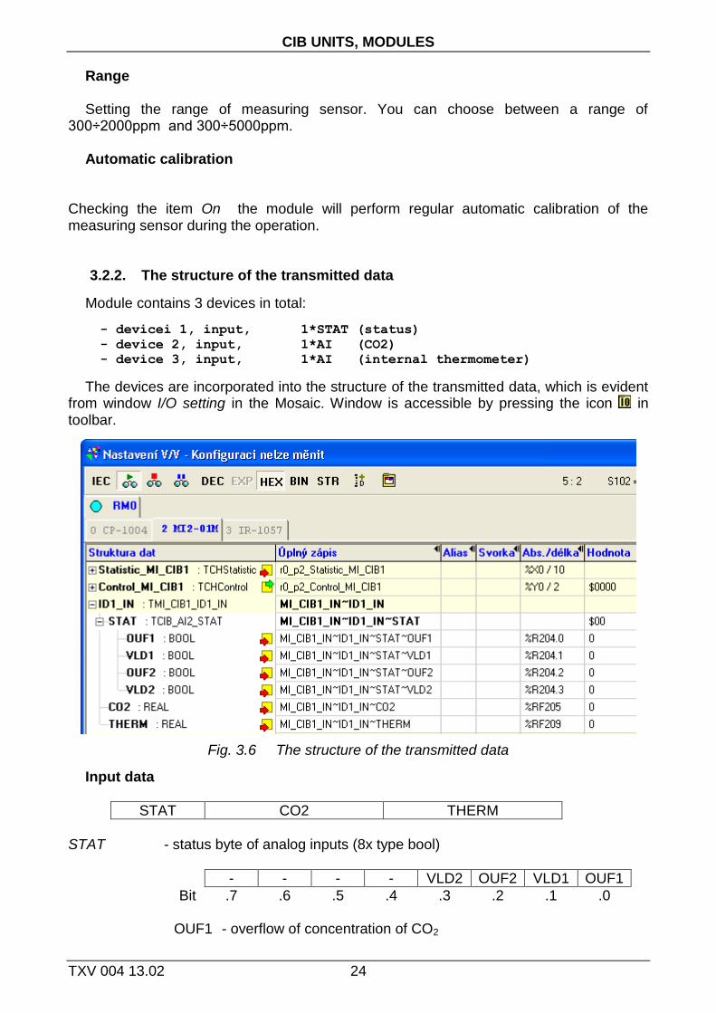
Range Setting the range of measuring sensor. You can choose between a range of
300÷2000ppm and 300÷5000ppm. Automatic calibration
Checking the item On the module will perform regular automatic calibration of the measuring sensor during the operation.
3.2.2. The structure of the transmitted data
Module contains 3 devices in total:
- devicei 1, input, 1*STAT (status)
- device 2, input, 1*AI (CO2)
- device 3, input, 1*AI (internal thermometer)
The devices are incorporated into the structure of the transmitted data, which is evident from window I/O setting in the Mosaic. Window is accessible by pressing the icon in toolbar.
Fig. 3.6 The structure of the transmitted data
Input data
STAT CO2 THERM
STAT - status byte of analog inputs (8x type bool)
- - - - VLD2 OUF2 VLD1 OUF1
Bit .7 .6 .5 .4 .3 .2 .1 .0
OUF1 - overflow of concentration of CO2

3.2. C-AQ-0001R
25 TXV 004 13.02 .
VLD1 - validity of reading of concentration of CO2 OUF2 - overflow / underflow of range of thermometer THERM VLD2 - validity of reading the thermometer THERM CO2 - concentration CO2 (type real) [ppm] (1ppm = 1part per million) THERM - temperature of auxiliary internal sensor (type real) [°C]

CIB UNITS, MODULES
TXV 004 13.02 26
3.3. C-AQ-0002R
Module for interior for measuring the presence of volatile gaseous pollutants (VOC - Volatile Organic Compounds) in the air. The detection is based on the electrochemical principle (conductivity measurement by selective semiconductor sensor). The module is particularly sensitive to toluene, hydrogen sulphide, ethanol, ammonia and hydrogen. In addition, you can also detect alcohol vapour, methane, propane, butane, natural gas and substances released from building materials, interior equipment. The module contains an auxiliary temperature sensor (measuring the temperature inside the module does not correspond to the ambient temperature module!!!).
Mechanical design of the module allows easy wall mounting. Tab. 3.3 Basic parameters C-AQ-0002R
C-AQ-000xR
CIB +
CIB -
Fig. 3. 7 View and connection C-AQ-0002R
3.3.1. Configuration
Fig. 3.8 Module configuration
VOC measuring input
The selectable ranges 0 ÷ 5 ppm 0 ÷ 50 ppm
Sensor warming after switch on
10 min
auxiliary temperature input
Sensor type Thermistor NTC 12k, internal
Range 0 ÷ +50 °C
Resolution 0,1 °C
Accuracy 0,8 °C
Power supply
Power supply and communication
24 V (27 V) from the CIB
Nominal power consumption
80 mA
Dimensions and weight
Dimensions 125 × 83 × 36mm
Weight 300g
Operating and installation conditions
Operating temperature 0 ÷ +40 °C
Storage temperature -20 ÷ +60 °C
IP degree of protection acc. IEC 529
IP20
Overvoltage category III
Degree of pollution according EN 61313
2
Operating position arbitrary
Installation on the wall
Connecting screw type terminals
Cross-section of wires max. 2,5 mm2

3.3. C-AQ-0002R
27 TXV 004 13.02 .
Range Selectable ranges. It is possible to select 0÷5ppm and 0÷50ppm. Auto adaptive mode Check box On the module will perform regular automatic adaptation of the measuring
sensor. 3.3.2. The structure of the transmitted data
Module contains 3 devices in total:
- device 1, input, 1*STAT (status)
- device 2, input, 1*AI (VOC)
- device 3, input, 1*AI (internal temperature)
The devices are incorporated into the structure of the transmitted data, which is evident from window I/O setting in the Mosaic. Window is accessible by pressing the icon in toolbar.
Fig. 3.9 The structure of the transmitted data
Input data
STAT VOC THERM
STAT - status byte of analog inputs (8x type bool)
- - - - VLD2 OUF2 VLD1 OUF1
Bit .7 .6 .5 .4 .3 .2 .1 .0
OUF1 - overflow of concentration of VOC

CIB UNITS, MODULES
TXV 004 13.02 28
VLD1 - validity of reading of concentration of VOC OUF2 - overflow / underflow of range of thermometer THERM VLD2 - validity of reading the thermometer THERM VOC - value of concentration of VOC (type real) [ppm] (1ppm = 1 part per million) THERM - temperature of auxiliary internal sensor (type real) [°C]

3.4. C-AQ-0003R
29 TXV 004 13.02 .
3.4. C-AQ-0003R
Module for interior for measuring the presence of smoke (carbon monoxide and hydrogen) in the air. The detection is based on the electrochemical principle (conductivity measurement by selective semiconductor sensor). The module can be used for detection of leakage of gases methane, propane, butane and natural gas. The module contains an auxiliary temperature sensor (measuring the temperature inside the module does not correspond to the ambient temperature module!!!).
Mechanical design of the module allows easy wall mounting. Tab. 3.4 Basic parameters C-AQ-0003R
C-AQ-000xR
CIB +
CIB -
Fig. 3. 10 View and connection C-AQ-0003R
3.4.1. Configuration
Fig. 3.11 Module configuration
Smoke measuring input
The selectable ranges 0 ÷ 5 ppm 0 ÷ 50 ppm
Sensor warming after switch on
10 min
auxiliary temperature input
Sensor type Thermistor NTC 12k, internal
Range 0 ÷ +50 °C
Resolution 0,1 °C
Accuracy 0,8 °C
Power supply
Power supply and communication
24 V (27 V) from the CIB
Nominal power consumption
80 mA
Dimensions and weight
Dimensions 125 × 83 × 36mm
Weight 300g
Operating and installation conditions
Operating temperature 0 ÷ +40 °C
Storage temperature -20 ÷ +60 °C
IP degree of protection acc. IEC 529
IP20
Overvoltage category III
Degree of pollution according EN 61313
2
Operating position arbitrary
Installation on the wall
Connecting screw type terminals
Cross-section of wires max. 2,5 mm2

CIB UNITS, MODULES
TXV 004 13.02 30
Range Setting the range of measuring sensor. You can choose between a range of 0÷5ppm
and 0÷50ppm. Auto adaptive mode Checking box On the module will perform regular automatic adaptation of measuring
sensor. 3.4.2. The structure of the transmitted data
Module contains 3 devices in total:
- device 1, input, 1*STAT (status )
- device 2, input, 1*AI (smoke)
- device 3, input, 1*AI (internal thermometer)
The devices are incorporated into the structure of the transmitted data, which is evident from window I/O setting in the Mosaic. Window is accessible by pressing the icon in toolbar.
Fig. 3.12 The structure of the transmitted data
Input data
STAT SMOKE THERM
STAT - status byte of analog inputs (8x type bool)
- - - - VLD2 OUF2 VLD1 OUF1
Bit .7 .6 .5 .4 .3 .2 .1 .0
OUF1 - overflow of concentration of SMOKE VLD1 - validity of reading of concentration of SMOKE OUF2 - overflow / underflow of range of thermometer THERM VLD2 - validity of reading the thermometer THERM MOKE - value of smoke concentration (type real) [ppm] (1ppm = 1 part per million) THERM - temperature of auxiliary internal sensor (type real) [°C]

3.5. C-AQ-0004R
31 TXV 004 13.02 .
3.5. C-AQ-0004R
Module for interior for measuring the relative humidity in the air Humidity is evaluated by capacitive polymer sensor. The module contains an auxiliary temperature sensor.
Mechanical design of the module allows easy wall mounting. Tab. 3.5 Basic parameters C-AQ-0004R
C-AQ-000xR
CIB +
CIB -
Fig. 3. 13 View and connection C-AQ-0004R
3.5.1. Configuration The module does not require additional configuration.
3.5.2. The structure of the transmitted data
Module contains 3 devices in total:
- device 1, input, 1*STAT (status )
- device 2, input, 1*AI (humidity)
- device 3, input, 1*AI (internal thermometer)
The devices are incorporated into the structure of the transmitted data, which is evident from window I/O setting in the Mosaic. Window is accessible by pressing the icon in toolbar.
Measuring input RH
Range 0 ÷ 100 % RH
Resolution 0,1 % RH
Accuracy 3,5 % RH (for RH 20 ÷ 80%)
5 % RH (for RH 0 ÷ 100%)
auxiliary temperature input
Sensor type Thermistor NTC 12k, internal
Range 0 ÷ +50 °C
Resolution 0,1 °C
Accuracy 0,8 °C
Power supply
Power supply and communication
24 V (27 V) from the CIB
Nominal power consumption
42 mA
Dimensions and weight
Dimensions 125 × 83 × 36mm
Weight 300g
Operating and installation conditions
Operating temperature 0 ÷ +40 °C
Storage temperature -20 ÷ +60 °C
IP degree of protection acc. IEC 529
IP20
Overvoltage category III
Degree of pollution according EN 61313
2
Operating position arbitrary
Installation on wall
Connection screw type terminals
Cross-section of wires max. 2,5 mm2

CIB UNITS, MODULES
TXV 004 13.02 32
Fig. 3.14 The structure of the transmitted data
Input data
STAT RH THERM
STAT - status byte of analog inputs (8x type bool)
- - - - VLD2 OUF2 VLD1 OUF1
Bit .7 .6 .5 .4 .3 .2 .1 .0
OUF1 - overflow / underflow of RH - relative humidity measuring VLD1 - validity of reading RH OUF2 - overflow / underflow of range of thermometer THERM VLD2 - validity of reading the thermometer THERM RH - value of RH relative humidity (type real) [%] THERM - temperature of auxiliary internal sensor (type real) [°C]

3.6. C-DL-0012S
33 TXV 004 13.02 .
3.6. C-DL-0012S
The module operates as a converter CIB bus on the bus DALI (according to specification NEMA Standards Publication 243-2004 ). DALI is bus specialized to control DALI lighting modules (ballasts). One converter C-DL-0012S can control up to 12 DALI ballasts. The converter has implemented system support for the "random" addressing the connected DALI ballasts.
The mechanical design of the module is designed to be mounted under cover of device (ingress protection of the module IP10B). Signals of the module are available on ribbon cable.
signalling green RUN LED is accessible from the side of module opposite to ribbon cable. Connecting on the CIB bus (connection to the power supply) is indicated by permanent lit of the RUN LED. Module operation on the CIB is indicated by regular flashing of the RUN LED.
Tab. 3.6 Basic parameters C-DL-0012S
Fig. 3. 15 View and connection C-DL-0012S
3.6.1. Configuration For software support of the module it is necessary library DaliLib.mlb imported in
Mosaic. Configuration and serving Dali network is then performed using function blocks of this library. For detailed description of the library see documentation TXV 003 66 Library
DALI
Number of connected DALI ballast
12
Supported "short addresses" of DALI ballast
0 ÷ 11, broadcast
Supported "group addresses" of DALI ballast
0 ÷ 15
Power supply
Power supply and communication
24 V (27 V) from the CIB
Nominal power consumption
22 mA
Max. power consumption
80 mA
Dimensions and weight
Dimensions max. 55 × 26 × 20mm
Weight 7 g
Operating and installation conditions
Operating temperature 0 ÷ +70 °C
Storage temperature -25 ÷ +85 °C
IP degree of protection acc. IEC 529
IP10B
Overvoltage category II (according to EN 60664)
Degree of pollution 1 (according to EN 60664)
Operating position arbitrary
Type of operation continuous
Installation
Type under cover of device
Connecting Ribbon cable 0.15 mm2

CIB UNITS, MODULES
TXV 004 13.02 34
DaliLib. If this library is not imported to the project, the project with the C-DL-0012S cannot be compiled !!!!
3.6.2. The structure of the transmitted data
Module contains 1 device in total:
- device 1, input/output, STAT+DATA_IN/CONT+DATA_OUT
The devices are incorporated into the structure of the transmitted data, which is evident from window I/O setting in the Mosaic. Window is accessible by pressing the icon in toolbar.
Fig. 3.16 The structure of the transmitted data
Input data
STAT DATA
STAT - status byte of module (8x type bool)
ARC DONE RRF RRE SHS RNDOK - -
Bit .7 .6 .5 .4 .3 .2 .1 .0
ARC - alternance bit of the receiver. In the case of the change this value one can accept the other bits in the STAT
DONE - flag of processing a request to send the message to the DALI bus

3.6. C-DL-0012S
35 TXV 004 13.02 .
0 = converter is ready for processing the request 1 = converter processed the request RRF - flag of the replies received from the DALI bus 1 = reply delivered RRE - error flag when receiving answers / at "random" addressing (if
the RRE is set at „random“ addressing, is in the input variable DATA specified error at the same time)
1 = error / collision when receiving answers / at "random" addressing
SHS - finding ballast in the "random" addressing RNDOK - Exit from "random" addressing (the entire address space
"random" addresses were searched) DATA - response of the DALI bus / error code (type 1 usint) error codes: 3 = Error of setting / verification of short addresses 4 = required short address is out of range
Input data
CONT ADDRESS COMMAND DATA
CONT - control word of module (8x type bool)
ACN TRG - - CHS RNDS DBL LENM
Bit .7 .6 .5 .4 .3 .2 .1 .0
ACN - Alternance bit of transmitter. When the value is changed, other bits in CONT (if the other bits in the CONT are zero the flags in STAT are reset = reset mode) are accepted.
TRG - request to send messages to the DALI bus CHS - Starting the search and addressing the ballast in the "random"
addressing, the required short address must be currently registered in the variable ADDRESS
RNDS - Activation of the mode "random" addressing DBL - requirement for multiple (double) sending the same message
to the DALI bus. Repeated message will be sent within 100ms from the first message (requirement of some DALI messages)
LENM - length of transmitted DALI message 0 = length 2 Byte (ADDRESS, COMMAND) 1 = length 3 Byte (ADDRESS, COMMAND, DATA) ADDRESS - address byte of DALI message (1x type usint) COMMAND - control byte of DALI message (1x type usint) DATA - data byte of DALI message (1x type usint)
Coding of DALI messages (in output variables ADDRESS, COMMAND and DATA) is defined by the DALI protocol specification.
3.6.3. Module specifics
CIB UNITS, MODULES
TXV 004 13.02 36
To serve the C-DL-0012S module it is necessary to install communication library
DaliLib.mlb (otherwise the project cannot be compiled!!!).

3.7. C-DL-0064M
37 TXV 004 13.02 .
3.7. C-DL-0064M
The module operates as a converter CIB bus on the bus DALI (according to specification NEMA Standards Publication 243-2004 ). DALI is bus specialized to control DALI lighting modules (ballasts). One converter C-DL-0064S can control up to 64 DALI ballasts. The converter has implemented system support for the "random" addressing the connected DALI ballasts.
Mechanical design corresponds to the modular design with width of 2M for mounting on the DIN-rail. After connecting the module to the CIB line (external power supply 24V DC) the green RUN LED lights still. If the module is served by the CIB (it communicates), green RUN LED flashes regularly.
Tab. 3.7 Basic parameters C-DL-0064M
Fig. 3. 17 View and connection C-DL-0064M
3.7.1. Configuration For software support of the module it is necessary library DaliLib.mlb imported in
Mosaic. Configuration and serving Dali network is then performed using function blocks of this library. For detailed description of the library see documentation TXV 003 66 Library DaliLib. If this library is not imported to the project, the project with the C-DL-0064S cannot be compiled !!!!
DALI
Number of connected DALI ballast
64
Supported "short addresses" of DALI ballast
0 ÷ 63, broadcast
Supported "group addresses" of DALI ballast
0 ÷ 15
Power supply and communication
Power supply 24 V (from external power supply)
Nominal power consumption
30 mA
Max. power consumption
320 mA
Communication CIB, DALI
Typical power consumption from CIB
0 mA
Dimensions and weight
Dimensions 106 × 92 × 35mm
Weight 65 g
Operating and installation conditions
Operating temperature 0 ÷ +70 °C
Storage temperature -25 ÷ +85 °C
IP degree of protection acc. IEC 529
IP10B
Overvoltage category II (according to EN 60664)
Degree of pollution 1 according to EN 60664
Operating position arbitrary
Type of operation continuous
Installation
Type on DIN rail
Connection terminals Screw-type
Cross-section of wires Max. 2,5 mm2

CIB UNITS, MODULES
TXV 004 13.02 38
3.7.2. The structure of the transmitted data
Module contains 1 device in total:
- device 1, input/output, STAT+DATA_IN/CONT+DATA_OUT
The devices are incorporated into the structure of the transmitted data, which is evident from window I/O setting in the Mosaic. Window is accessible by pressing the icon in toolbar.
Fig. 3.18 The structure of the transmitted data
Input data
STAT DATA
STAT - status byte of module (8x type bool)
ARC DONE RRF RRE SHS RNDOK - -
Bit .7 .6 .5 .4 .3 .2 .1 .0
ARC - alternance bit of the receiver. In the case of the change this value one can accept the other bits in the STAT
DONE - flag of processing a request to send the message to the DALI bus
0 = converter is ready for processing the request 1 = converter processed the request RRF - flag of the replies received from the DALI bus 1 = the reply was delivered
3.7. C-DL-0064M
39 TXV 004 13.02 .
RRE - error flag when receiving answers / at "random" addressing (if the RRE is set at „random“ addressing, is in the input variable DATA specified error at the same time)
1 = error / collision when receiving answers / at "random" addressing
SHS - finding ballast in the "random" addressing RNDOK - Exit from "random" addressing (the entire address space
"random" addresses were searched) DATA - response of the DALI bus / error code (type 1 usint) error codes: 3 = Error of setting / verification of short addresses 4 = required short address is out of range
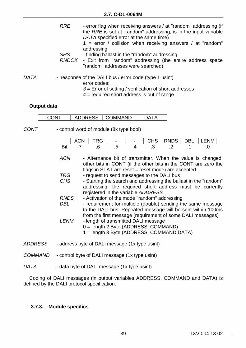
Output data
CONT ADDRESS COMMAND DATA
CONT - control word of module (8x type bool)
ACN TRG - - CHS RNDS DBL LENM
Bit .7 .6 .5 .4 .3 .2 .1 .0
ACN - Alternance bit of transmitter. When the value is changed, other bits in CONT (if the other bits in the CONT are zero the flags in STAT are reset = reset mode) are accepted.
TRG - request to send messages to the DALI bus CHS - Starting the search and addressing the ballast in the "random"
addressing, the required short address must be currently registered in the variable ADDRESS
RNDS - Activation of the mode "random" addressing DBL - requirement for multiple (double) sending the same message
to the DALI bus. Repeated message will be sent within 100ms from the first message (requirement of some DALI messages)
LENM - length of transmitted DALI message 0 = length 2 Byte (ADDRESS, COMMAND) 1 = length 3 Byte (ADDRESS, COMMAND DATA) ADDRESS - address byte of DALI message (1x type usint) COMMAND - control byte of DALI message (1x type usint) DATA - data byte of DALI message (1x type usint)
Coding of DALI messages (in output variables ADDRESS, COMMAND and DATA) is defined by the DALI protocol specification.
3.7.3. Module specifics

CIB UNITS, MODULES
TXV 004 13.02 40
To serve the C-DL-0012S module it is necessary to install communication library DaliLib.mlb (otherwise the project cannot br compiled!!!).

3.8. C-DM-0006M-ILED
41 TXV 004 13.02 .
3.8. C-DM-0006M-ILED
The module is designed for the current control of LED light sources e.g. LED chips). It
includes 6 analog outputs for continuous control of up to 6 separate light sources (or 2 RGB light sources). The supply voltage for light sources is an external one in the range 4.5 to 48V DC. Nominal output current can be adjusted in steps of 150, 350, 500, or 700mA. The individual outputs can be locally manually controlled by buttons on the module. Mechanical design corresponds to the modular design with width of 3M for mounting on the DIN-rail.
The module is protected against overheating, when all outputs will be disconnected. Overheating is indicated in the status variable module.
After connecting the module to the CIB line (power connected) the green RUN LED lights still. If the module is served by the CIB (it communicates), green RUN LED flashes regularly.
Tab. 3.8 Basic parameters C-DM-0006M-ILED
Fig. 3. 19 View and connection C-DM-0006M-ILED
Analog outputs for LED lights
Quantity 6
Nominal output current 150/350/500/700mA
Total output current Max. 4.2A
Current of LED+ terminal
Max. 10A
Overload protection No
Overheating protection Yes
Power for LED outputs
External supply 4.5 ÷ 48V DC, 5A
Power of module
Power supply and communication
24 V (27 V) from the CIB
Max. power consumption
15 mA
Dimensions and weight
Dimensions 90 × 58 × 53mm
Weight 120g
Operating and installation conditions
Operating temperature 0 ÷ +45 °C
Storage temperature -25 ÷ +85 °C
IP degree of protection acc. IEC 529
IP20B
Operating position arbitrary
Type of operation continuous
Installation on DIN rail
Connection terminals
Type Screw-type
Cross-section of wires Max. 4 mm2

CIB UNITS, MODULES
TXV 004 13.02 42
3.8.1. Configuration
Fig. 3.20 Module configuration
Block setting For individual LED outputs can be set whether the module during transition into HALT
mode has to froze its outputs or whether the outputs has to be cleared. Ramp settings For individual LED outputs can be set up the step for leading (falling) ramp to overrun
from 0 to 100% (and vice versa). You can choose between steps of 100ms or steps of 1000ms. The specific ramp values are passed to the module in output data.
Nominal current For each LED output can be set to the rated output current (representing the value of
the output set at 100%). The current can be set for 150, 350, 500, 700mA. Block of manual mode To check the box the ability of manual control of specific LED outputs in RUN mode is
blocked. In the HALT mode the manual control of LED outputs is allowed always. In RUN mode, the manual control is activated by pressing the button MANUAL
CONTROL on module. At the same time the yellow indicator LED lights up ON. Then it is possible to change the status of each output (0% / 100%). Another pressing the button MANUAL CONTROL LED indicator ON goes off and the manual mode is cancelled. Then LED outputs are controlled according to the commands of the CIB line. Activity of manual mode is also indicated in the module status variable STAT.ManMode.

3.8. C-DM-0006M-ILED
43 TXV 004 13.02 .
3.8.1. The structure of the transmitted data
Module contains 4 devices in total:
- device 1, input, 1*STAT (status )
- device 2, input, 1*thermometer
- device 3, output, 3*AO (1-3)
- device 4, output, 3*AO (4-6)
The devices are incorporated into the structure of the transmitted data, which is evident
from window I/O setting in the Mosaic. Window is accessible by pressing the icon in toolbar.
Fig. 3.21 The structure of the transmitted data
Input data
STAT iTHERM
STAT - status byte of module (8x type bool)
OverHeat ManMode - - - - - -
Bit .7 .6 .5 .4 .3 .2 .1 .0
ManMode - signalling of manual mode of LED outputs. OverHeat - overheating of module (LED outputs are disconnected) iTHERM - internal module temperature (type real) [°C]

CIB UNITS, MODULES
TXV 004 13.02 44
Output data
LEDa LEDb
LEDx - the value of analog LEDx output (type real), 0÷100[%] rampx - the value of leading/falling ramp of LEDx output (type usint), 0÷255 Depending on the selected step value it represents the ramp either
0÷255s or 0÷25.5s.

3.9. C-DM-0006M-ULED
45 TXV 004 13.02 .
3.9. C-DM-0006M-ULED
The module is designed for the voltage control of LED light sources e.g. LED stripes). It includes 6 analog outputs for continuous control of up to 6 separate light sources (or 2 RGB light sources). The supply voltage for light sources is an external one (12V or 24V). Each output can be locally manually controlled by buttons on the module. Mechanical design corresponds to the modular design with width of 3M for mounting on the DIN-rail.
The individual LED outputs are protected against short circuit. During short circuit indication the respective output circuit turns off and the LED indicator is flashing. The module is also protected against overheating when the output is disconnected. Short circuit and overheating is indicated in the status variable module.
After connecting the module to the CIB line (power connected) the green RUN LED lights still. If the module is served by the CIB (it communicates), green RUN LED flashes regularly.
Tab. 3.9 Basic parameters C-DM-0006M-ULED
CI BUS LED POWER 12/24 V
A5 A6 A7A1 A2 A3 A4
B9B8B7B6B5B4B3B2B1
VOLTAGE OUTPUTS
RUN
LED1
MANUAL CONTROLON
LED2 LED3 LED6LED5LED4
L L LLLLLLLE E EEEEEEE
D D DDDDDDD
+ + +654321
---
---
12/24 V
HW ADDRESS 19AE
CIB
+
CIB+
L1+
CIB+
CIB-
L1-
CIB-
CIB
+
N.C
.
Uin
+
GN
D
CIB
-
Fig. 3. 22 View and connection C-DM-0006M-ULED
Analog outputs for LED lights
Quantity 6
Output voltage 12/24V DC
Current of LED1-6 terminal
Max. 6A
Current of LED+ terminal
Max. 10A
Total output current Max. 24A
Overload protection Yes
Power for LED outputs
External supply 12/24V DC, max. 24A
Power module
Power supply and communication
24 V (27 V) from the CIB
Max. power consumption
15 mA
Dimensions and weight
Dimensions 90 × 58 × 53mm
Weight 100g
Operating and installation conditions
Operating temperature 0 ÷ +45 °C
Storage temperature -25 ÷ +85 °C
IP degree of protection acc. IEC 529
IP10B
Operating position arbitrary
Type of operation continuous
Installation on DIN rail
Connection terminals
CIB Screw-type
LED Screw-type,, removable
Cross section of CIB, LED wires
Max. 2,5 mm2
External power for LED Screw-type
Cross section of wires of external supply of LED
Max. 4 mm2

CIB UNITS, MODULES
TXV 004 13.02 46
3.9.1. Configuration
Fig. 3.23 Module configuration
Block setting For individual LED outputs can be set whether the module during transition into HALT
mode has to froze its outputs or whether the outputs has to be cleared. Ramp settings For individual LED outputs can be set up the step for leading (falling) ramp to overrun
from 0 to 100% (and vice versa). The specific ramp values are passed to the module in output data.
Block of manual mode Checking the box the ability to manually control specific LED outputs in RUN mode is
blocked. In the HALT mode the manual control of LED outputs is allowed always. In RUN mode, the manual control is activated by pressing the button MANUAL
CONTROL on module. At the same time the yellow indicator LED lights up ON. Then it is possible to change the status of each output (0% / 100%).Another pressing the button MANUAL CONTROL LED indicator ON goes off and the manual mode is cancelled. Then LED outputs are controlled according to the commands of the CIB line. Activity of manual mode is also indicated in the module status variable STAT.ManMode.
3.9.2. The structure of the transmitted data
Module contains 4 devices in total: - device 1, input, 1*STAT (status )
- device 2, input, 1*thermometer
- device 3, output, 3*AO
- device 4, output, 3*AO

3.9. C-DM-0006M-ULED
47 TXV 004 13.02 .
The devices are incorporated into the structure of the transmitted data, which is evident from window I/O setting in the Mosaic. Window is accessible by pressing the icon in toolbar.
Fig. 3.24 The structure of the transmitted data
Input data
STAT iTHERM
STAT - status byte of module (8x type bool)
OverHeat ManMode OverLoad6 … … … … OverLoad1
Bit .7 .6 .5 .4 .3 .2 .1 .0
OverLoadx - short circuit on LEDx output ManMode - signalling of manual mode of LED outputs. OverHeat - overheating of module (LED outputs are disconnected) iTHERM - internal module temperature (type real) [°C]
Output data
LEDa LEDb
LEDx - the value of analog LEDx output (type real), 0÷100[%] rampx - the value of leading/falling ramp of LEDx output (type usint), 0÷255 Depending on the selected step value it represents the ramp either
0÷255s or 0÷25.5s.
CIB UNITS, MODULES
TXV 004 13.02 48
3.10. C-DM-0402M-RLC
The module is designed to control the light intensity (luminous flux) of most dimmable
loads powered by mains voltage 230 V . It includes 2 dimmer outputs and 4 universal AI/DI inputs (configurable in pairs). The dimmer is suitable for dimming resistive, inductive or capacitive loads. Dimmer works on the principle of phase control of the angle of the on or off.
Each output can be locally manually controlled by buttons on the module (ON/OFF). The outputs are protected against short circuit and overheating module.
After connecting the module to the CIB line (power connected) the green RUN LED lights still. If the module is served by the CIB (it communicates), green RUN LED flashes regularly. Mechanical design corresponds to the modular design with width of 3M for mounting on the DIN-rail.

3.10. C-DM-0402M-RLC
49 TXV 004 13.02 .
Tab. 3.10 Basic parameters C-DM-0402M-RLC
Fig. 3. 25 View and connecting C-DM-0402M-RLC
Dimmer outputs OUT
Quantity 2
Type of load R, L, C, RL, RC, LED, CFL
Power load 230V AC / 50Hz
Switching power Max. 2 x 500 VA*)
Output current Max. 2 x 2.2A
Overload protection Yes
Overheating protection Yes
Parallel work Yes, max. 4 channels (on the same CIB line)
The power element NMOS transistor
Universal inputs AI/DI
Quantity 4
Optional input type Binary (button), balanced (for security detectors), Pt1000, Ni1000, NTC12kΩ, KTY81-121, resistance 160kΩ
Binary input NO contact (0/1) (Normally Open)
Balanced input for security detectors
Resistance 1x2k2, or 2x1k1
Pt1000 –90 ÷ +320 °C
Ni1000 –60 ÷ +200 °C
NTC 12kΩ –40 ÷ +125 °C
KTY81-121 –55 ÷ +125 °C
Resistance input 0 ÷ 160kΩ
Resolution, Accuracy 0.1 °C / 10Ω, 0.5 % of range
Period of refresh AI typically 5s
Power module
Power supply and communication
24 V (27 V) from the CIB
Max. power consumption
20 mA
Dimensions and weight
Dimensions 90 × 58 × 53mm
Weight 120g
Operating and installation conditions
Operating temperature 0 ÷ +55 °C*)
Storage temperature -25 ÷ +85 °C
IP degree of protection acc. IEC 529
IP20
Operating position vertical
Type of operation continuous
Installation on DIN rail
Connection terminals
Type Screw-type
Cross-section of wires Max. 2,5 mm2
*) because of the module cooling, spacing between modules is
recommended min. 15mm (temperature derating curve module see next)
CIB UNITS, MODULES
TXV 004 13.02 50
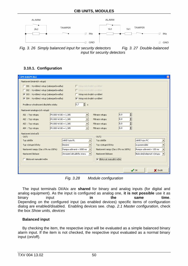
Fig. 3. 26 Simply balanced input for security detectors Fig. 3. 27 Double-balanced input for security detectors
3.10.1. Configuration
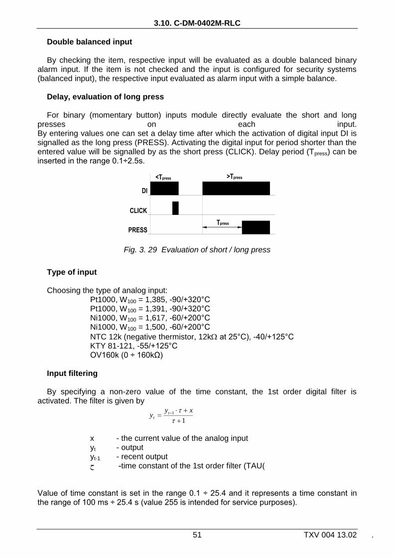
Fig. 3.28 Module configuration
The input terminals DI/AIx are shared for binary and analog inputs (for digital and
analog equipment). As the input is configured as analog one, it is not possible use it as binary input in the same time. Depending on the configured input (as enabled devices) specific items of configuration dialog are enabled/disabled. Enabling devices see. chap. 2.1 Master configuration, check the box Show units, devices
Balanced input By checking the item, the respective input will be evaluated as a simple balanced binary
alarm input. If the item is not checked, the respective input evaluated as a normal binary input (on/off).
3.10. C-DM-0402M-RLC
51 TXV 004 13.02 .
Double balanced input By checking the item, respective input will be evaluated as a double balanced binary
alarm input. If the item is not checked and the input is configured for security systems (balanced input), the respective input evaluated as alarm input with a simple balance.
Delay, evaluation of long press For binary (momentary button) inputs module directly evaluate the short and long
presses on each input. By entering values one can set a delay time after which the activation of digital input DI is signalled as the long press (PRESS). Activating the digital input for period shorter than the entered value will be signalled by as the short press (CLICK). Delay period (Tpress) can be inserted in the range 0.1÷2.5s.
Fig. 3. 29 Evaluation of short / long press
Type of input Choosing the type of analog input:
Pt1000, W100 = 1,385, -90/+320°C Pt1000, W100 = 1,391, -90/+320°C Ni1000, W100 = 1,617, -60/+200°C Ni1000, W100 = 1,500, -60/+200°C
NTC 12k (negative thermistor, 12k at 25°C), -40/+125°C KTY 81-121, -55/+125°C OV160k (0 ÷ 160kΩ)
Input filtering By specifying a non-zero value of the time constant, the 1st order digital filter is
activated. The filter is given by
1
1
xyy t
t
x - the current value of the analog input yt - output yt-1 - recent output time constant of the 1st order filter (TAU) - ح
Value of time constant is set in the range 0.1 ÷ 25.4 and it represents a time constant in the range of 100 ms ÷ 25.4 s (value 255 is intended for service purposes).
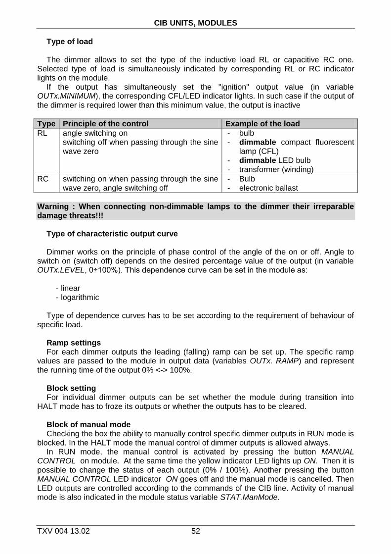
CIB UNITS, MODULES
TXV 004 13.02 52
Type of load The dimmer allows to set the type of the inductive load RL or capacitive RC one.
Selected type of load is simultaneously indicated by corresponding RL or RC indicator lights on the module.
If the output has simultaneously set the "ignition" output value (in variable OUTx.MINIMUM), the corresponding CFL/LED indicator lights. In such case if the output of the dimmer is required lower than this minimum value, the output is inactive
Type Principle of the control Example of the load
RL angle switching on switching off when passing through the sine wave zero
- bulb - dimmable compact fluorescent
lamp (CFL) - dimmable LED bulb - transformer (winding)
RC switching on when passing through the sine wave zero, angle switching off
- Bulb - electronic ballast
Warning : When connecting non-dimmable lamps to the dimmer their irreparable damage threats!!!
Type of characteristic output curve Dimmer works on the principle of phase control of the angle of the on or off. Angle to
switch on (switch off) depends on the desired percentage value of the output (in variable OUTx.LEVEL, 0÷100%). This dependence curve can be set in the module as:
- linear - logarithmic
Type of dependence curves has to be set according to the requirement of behaviour of
specific load. Ramp settings For each dimmer outputs the leading (falling) ramp can be set up. The specific ramp
values are passed to the module in output data (variables OUTx. RAMP) and represent the running time of the output 0% <-> 100%.
Block setting For individual dimmer outputs can be set whether the module during transition into
HALT mode has to froze its outputs or whether the outputs has to be cleared. Block of manual mode Checking the box the ability to manually control specific dimmer outputs in RUN mode is
blocked. In the HALT mode the manual control of dimmer outputs is allowed always. In RUN mode, the manual control is activated by pressing the button MANUAL
CONTROL on module. At the same time the yellow indicator LED lights up ON. Then it is possible to change the status of each output (0% / 100%). Another pressing the button MANUAL CONTROL LED indicator ON goes off and the manual mode is cancelled. Then LED outputs are controlled according to the commands of the CIB line. Activity of manual mode is also indicated in the module status variable STAT.ManMode.

3.10. C-DM-0402M-RLC
53 TXV 004 13.02 .
3.10.2. The structure of the transmitted data
Module contains 6 devices in total:
- device 1, input, 4*DI/EZS
- device 2, input/output, 1*DIMM (OUT1)
- device 3, input/output, 1*DIMM (OUT2)
- device 4, input, STAT + THERM
- device 5, input, 2*AI (AI1, AI2)
- device 6, input, 2*AI (AI3, AI4)
The devices are incorporated into the structure of the transmitted data, which is evident from window I/O setting in the Mosaic. Window is accessible by pressing the icon in toolbar.
Fig. 3.30 The structure of the transmitted data
Input data
DI ACT_LEVEL1 ACT_LEVEL2 STAT THERM AI1 AI2 AI3 AI4
DI - status of binary inputs, signalling "tamper" status of alarm inputs (16x
bool)
CLICK4 CLICK3 CLICK2 CLICK1 DI4 DI3 DI2 DI1
Bit .7 .6 .5 .4 .3 .2 .1 .0
TAMPER4 TAMPER3 TAMPER2 TAMPER1 PRESS4 PRESS3 PRESS2 PRESS1
Bit .15 .14 .13 .12 .11 .10 .9 .8
DIx - Current status of binary input DIx / alarm input x CLICKx - short pulse (to log. 1) on input DIx

CIB UNITS, MODULES
TXV 004 13.02 54
PRESSx - long pulse (to log. 1) on input DIx TAMPERx - „tamper“ status of alarm input x ACT_LEVELx - current status of output OUTx (type real) [%] STAT - status byte of module (16x type bool)
VLD4 OUF4 VLD3 OUF3 VLD2 OUF2 VLD1 OUF1
Bit .7 .6 .5 .4 .3 .2 .1 .0
- PWR_ERR HEAT ERR2 ERR1 MAN VLDT OUFT
Bit .15 .14 .13 .12 .11 .10 .9 .8
OUFx - overflow / underflow of analog input AIx VLDx - validity of reading of analog input AIx OUFT - overflow / underflow of internal thermometer range VLDT - internal thermometer reading validity ManMode - signalling of manual mode of dimmer outputs. ERRx - overload / short circuit on the output OUTx (the output x is
disconnected ) HEAT - thermal overheating module If the temperature of the module will be higher than 65 ° C, it will
automatically relieve both outputs transition to the "ignition" value. If the temperature is higher than 70 ° C, it will automatically disconnect both outputs.. The return to normal operating mode occurs automatically after cooling module temperature below 60 ° C.
PWR_ERR - main power 230V AC is not connected iTHERM - internal module temperature (type real) [°C] AIx - value of analog input AIx (type real) [°C],[kΩ] The value of temperature sensor is transferred in °C (with resolution of
0.1°C), the value of general resistance in range 160kΩ is transferred in kΩ (with resolution of 10Ω).
Output data
OUT1 OUT2
OUTx.LEVEL - value of output OUTx (type real), 0÷100[%] OUTx.RAMP - the value of leading/falling ramp of output OUTx (type usint), 0÷255 Depending on the selected step of ramp the value represents a ramp of
length 0 ÷ 255s, or 0 to 25.5s. The ramp represents the running time output 0% <-> 100%.
OUTx.MINIMUM - "ignition" value of output OUTx (type real), 0÷100[%] In such case if the output of the dimmer (in value OUTx.LEVEL) is
required lower than this minimum value, the output is inactive. This variable is automatically reset on value 20%.

3.10. C-DM-0402M-RLC
55 TXV 004 13.02 .
3.10.3. Module specifics
System support of CFox master For proper function of the module C-DM-0402-RLC the system support is required in
CFox master. This system support has been implemented into CFox master CF-1140 / CF-1141 in FW version 1.7 (into master MI2-01M / MI2-02M in version 2.0). If the master versions is lower, dimmer module will not work correctly (outputs will not be operated, ERR LED will flash 3 times briefly)
Operating temperature and self heating of the module To ensure the stable operation of the module it is necessary to keep the maximum
permissible ambient temperature. The inner space of the module during operation is additionally heated by own heat dissipation, which is proportional to dimming load of both the channel and to the character of dimming. For maximum performance, especially when installing multiple dimmers together, it is appropriate to use active cooling (fan, etc.), which ensures controlled airflow around the dimmers. Due to the cooling of module the lateral spacing between the modules in width min. 15mm is also recommended.
Eventual overheating of the module is automatically diagnosed and signalled (see chapter Diagnostics module below). Influence of ambient temperature on the power capabilities of the module is shown in the following chart.
Paralleling the outputs of the dimmer
If the required control output loads are beyond the performance capabilities of one output, it is possible to connected more outputs in parallel for one load. Up to 4 outputs can be interconnected in parallel way. Modules C-DM-0402M-RLC of such interconnected outputs has to be connected on the same CIB line. When configuring the module it is necessary to have all interconnected outputs identically configured and operated. Otherwise, there would be an overload of individual outputs and subsequent shutdown of all interconnected outputs.
In manual control mode such parallel interconnected outputs it is recommended to change

CIB UNITS, MODULES
TXV 004 13.02 56
the status of individual outputs (by buttons on the module) when the power is off (disconnected fuse / circuit breaker is off).
3.10.4. Module diagnostics
Dimmer includes a number of diagnostic tools for operation of the module. Result of diagnosis is available in the status byte of module STAT (see chapter structure of the transmitted data). Some results of diagnosis are also signalled via LEDs on the module.. The meaning is described in the following table.
ERR LED Description
Still lights Overload evaluated (short circuit) of the output (signalling in STAT.ERRx ). The output is automatically turned off (function of breaker). Unlocking the output is performed: a) by pressing the appropriate button OUTx or b) by writing the value 0% into variable OUTx.LEVEL.
1x short flash module is overheated (signalling in STAT.HEAT). Both outputs are automatically set into "ignition" value (> 65 ° C).When the temperature continues to rise the outputs turn off (>70°C). Unlocking outputs is performed automatically after cooling module (below 60 ° C)
2x short flash PWR_ERR - main power 230V AC is not connected
3x short flash The system support from CFox master is not available, the outputs will not be operated. It is necessary to upgrade firmware in the master. See chapter Module Specifics above.

3.11. C-HC-0201F-E
57 TXV 004 13.02 .
3.11. C-HC-0201F-E
Module is the proportional (continuous) drive to control the central heating radiator valves. The module - drive - contains an internal temperature sensor and 2 universal inputs, which can be connected to either an external resistive temperature sensor or an external binary signal (e.g. window contact). The module is equipped with an automatic adaptation of the drive depending on the used valve and with the function of regular spinning tracks valve (prevention valve seizure).For diagnostic functions module contains a signalling LED and control button MAN (both available after removing the module cover).Connecting the CIB is indicated RUN LED, module in operation is indicated by flashing RUN LED.
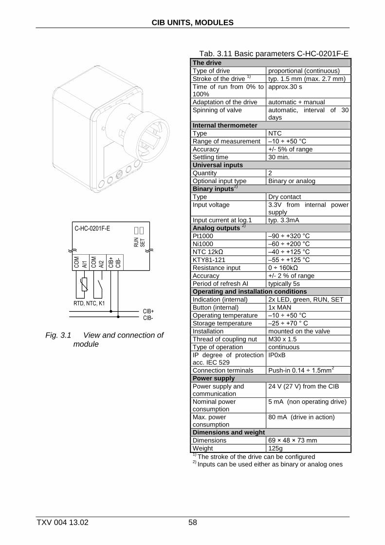
CIB UNITS, MODULES
TXV 004 13.02 58
Tab. 3.11 Basic parameters C-HC-0201F-E
Fig. 3.1 View and connection of module
The drive
Type of drive proportional (continuous)
Stroke of the drive 1)
typ. 1.5 mm (max. 2.7 mm)
Time of run from 0% to 100%
approx.30 s
Adaptation of the drive automatic + manual
Spinning of valve automatic, interval of 30 days
Internal thermometer
Type NTC
Range of measurement –10 ÷ +50 °C
Accuracy +/- 5% of range
Settling time 30 min.
Universal inputs
Quantity 2
Optional input type Binary or analog
Binary inputs2)
Type Dry contact
Input voltage 3.3V from internal power supply
Input current at log.1 typ. 3.3mA
Analog outputs 2)
Pt1000 –90 ÷ +320 °C
Ni1000 –60 ÷ +200 °C
NTC 12kΩ –40 ÷ +125 °C
KTY81-121 –55 ÷ +125 °C
Resistance input 0 ÷ 160kΩ
Accuracy +/- 2 % of range
Period of refresh AI typically 5s
Operating and installation conditions Indication (internal) 2x LED, green, RUN, SET
Button (internal) 1x MAN
Operating temperature –10 ÷ +50 °C
Storage temperature –25 ÷ +70 ° C
Installation mounted on the valve
Thread of coupling nut M30 x 1.5
Type of operation continuous
IP degree of protection acc. IEC 529
IP0xB
Connection terminals Push-in 0.14 ÷ 1.5mm2
Power supply
Power supply and communication
24 V (27 V) from the CIB
Nominal power consumption
5 mA (non operating drive)
Max. power consumption
80 mA (drive in action)
Dimensions and weight
Dimensions 69 × 48 × 73 mm
Weight 125g 1)
The stroke of the drive can be configured 2)
Inputs can be used either as binary or analog ones

3.11. C-HC-0201F-E
59 TXV 004 13.02 .
3.11.1. Configuration
Fig. 3.2 Module configuration
The input terminals AI1 and AI2 are shared for both binary and analog inputs (for
digital and analog equipment). As the input is configured as analog one, it is not possible use it as binary input in the same time. Depending on the configured input (as enabled devices) specific items of configuration dialog are enabled/disabled. Enabling devices see. chap.2.1 Master configuration , check the box Show units, devices .
Type of input Choosing the type of analog input:
Pt1000, W100 = 1,385, -90/+320°C Pt1000, W100 = 1,391, -90/+320°C Ni1000, W100 = 1,617, -60/+200°C Ni1000, W100 = 1,500, -60/+200°C
NTC 12k (negative thermistor, 12k at 25°C), -40/+125°C KTY 81-121, -55/+125°C OV600k (0 ÷ 630kΩ) OV6M (0 ÷ 6,5MΩ)
Input filtering By specifying a non-zero value of the time constant, the 1st order digital filter is
activated. The filter is given by
1
1
xyy t
t
x - the current value of the analog input yt - output yt-1 - recent output time constant of the 1st order filter (TAU) - ح
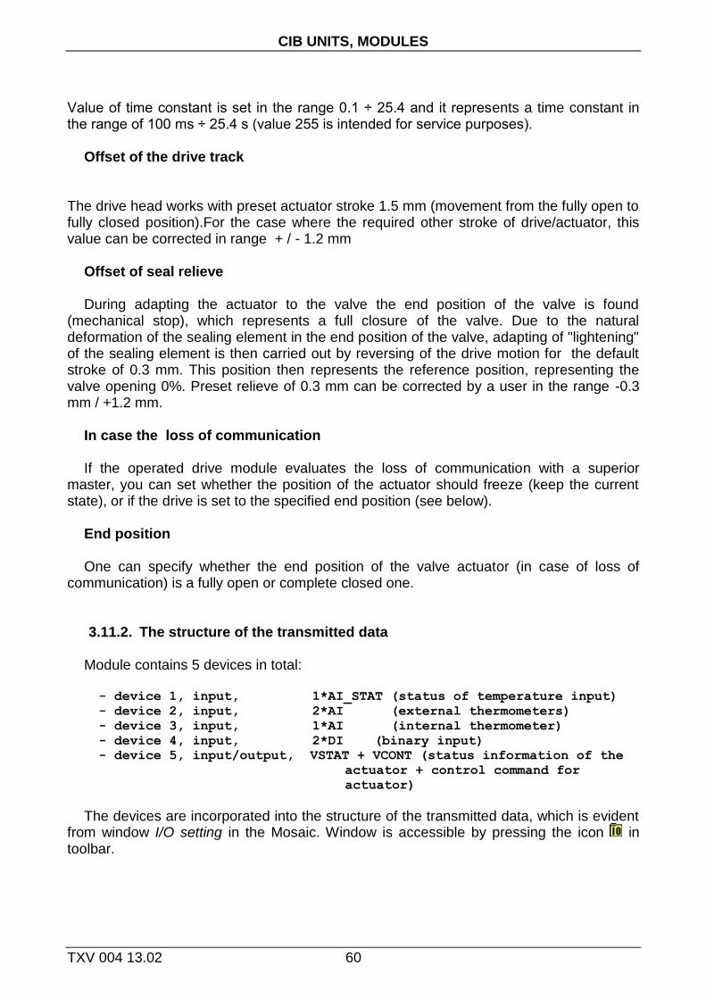
CIB UNITS, MODULES
TXV 004 13.02 60
Value of time constant is set in the range 0.1 ÷ 25.4 and it represents a time constant in the range of 100 ms ÷ 25.4 s (value 255 is intended for service purposes).
Offset of the drive track
The drive head works with preset actuator stroke 1.5 mm (movement from the fully open to fully closed position).For the case where the required other stroke of drive/actuator, this value can be corrected in range + / - 1.2 mm
Offset of seal relieve During adapting the actuator to the valve the end position of the valve is found
(mechanical stop), which represents a full closure of the valve. Due to the natural deformation of the sealing element in the end position of the valve, adapting of "lightening" of the sealing element is then carried out by reversing of the drive motion for the default stroke of 0.3 mm. This position then represents the reference position, representing the valve opening 0%. Preset relieve of 0.3 mm can be corrected by a user in the range -0.3 mm / +1.2 mm.
In case the loss of communication If the operated drive module evaluates the loss of communication with a superior
master, you can set whether the position of the actuator should freeze (keep the current state), or if the drive is set to the specified end position (see below).
End position One can specify whether the end position of the valve actuator (in case of loss of
communication) is a fully open or complete closed one. 3.11.2. The structure of the transmitted data
Module contains 5 devices in total:
- device 1, input, 1*AI_STAT (status of temperature input)
- device 2, input, 2*AI (external thermometers)
- device 3, input, 1*AI (internal thermometer)
- device 4, input, 2*DI (binary input)
- device 5, input/output, VSTAT + VCONT (status information of the
actuator + control command for
actuator)
The devices are incorporated into the structure of the transmitted data, which is evident from window I/O setting in the Mosaic. Window is accessible by pressing the icon in toolbar.

3.11. C-HC-0201F-E
61 TXV 004 13.02 .
Fig. 3.3 The structure of the transmitted data
Input data
STAT AI iTHERM DI VSTAT
STAT - status byte of temperature inputs (8x type bool)
- - VLDI OUFI VLD2 OUF2 VLD1 OUF1
Bit .7 .6 .5 .4 .3 .2 .1 .0
OUFx - overflow/underflow of the range of external temperature sensor x VLDx - validity of the reading of external temperature sensor x OUFI - overflow/underflow of the range of internal temperature sensor x VLDx - validity of the reading of internal temperature sensor x
AI - value of analog inputs (2x type real) [°C],[kΩ] AI1 - value of analog input AI1 AI2 - value of analog input AI2 The value of temperature sensor is transferred in °C (with resolution of
0.1°C), the value of general resistance in range 160kΩ is transferred in kΩ (with resolution of 10Ω).
THERM - temperature of auxiliary internal sensor (type real) [°C]
DI - status of binary inputs (8x type bool)
- - - - - - DI2 DI1
Bit .7 .6 .5 .4 .3 .2 .1 .0
DI1 - the current status of the binary DI1 input DI2 - the current status of the binary DI2 input
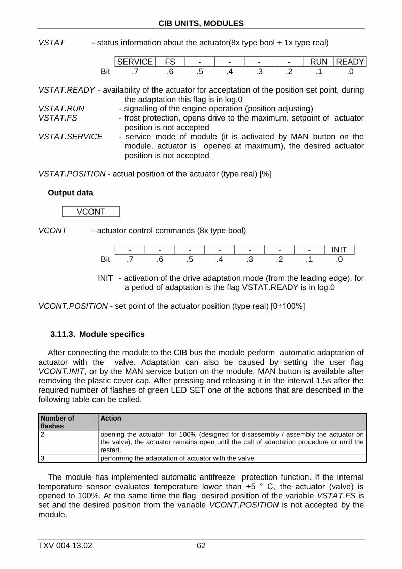
CIB UNITS, MODULES
TXV 004 13.02 62
VSTAT - status information about the actuator(8x type bool + 1x type real)
SERVICE FS - - - - RUN READY
Bit .7 .6 .5 .4 .3 .2 .1 .0
VSTAT.READY - availability of the actuator for acceptation of the position set point, during the adaptation this flag is in log.0
VSTAT.RUN - signalling of the engine operation (position adjusting) VSTAT.FS - frost protection, opens drive to the maximum, setpoint of actuator
position is not accepted VSTAT.SERVICE - service mode of module (it is activated by MAN button on the
module, actuator is opened at maximum), the desired actuator position is not accepted
VSTAT.POSITION - actual position of the actuator (type real) [%]
Output data
VCONT
VCONT - actuator control commands (8x type bool)
- - - - - - - INIT
Bit .7 .6 .5 .4 .3 .2 .1 .0
INIT - activation of the drive adaptation mode (from the leading edge), for a period of adaptation is the flag VSTAT.READY is in log.0
VCONT.POSITION - set point of the actuator position (type real) [0÷100%]
3.11.3. Module specifics
After connecting the module to the CIB bus the module perform automatic adaptation of actuator with the valve. Adaptation can also be caused by setting the user flag VCONT.INIT, or by the MAN service button on the module. MAN button is available after removing the plastic cover cap. After pressing and releasing it in the interval 1.5s after the required number of flashes of green LED SET one of the actions that are described in the following table can be called.
Number of flashes
Action
2 opening the actuator for 100% (designed for disassembly / assembly the actuator on the valve), the actuator remains open until the call of adaptation procedure or until the restart.
3 performing the adaptation of actuator with the valve
The module has implemented automatic antifreeze protection function. If the internal
temperature sensor evaluates temperature lower than +5 ° C, the actuator (valve) is opened to 100%. At the same time the flag desired position of the variable VSTAT.FS is set and the desired position from the variable VCONT.POSITION is not accepted by the module.

3.11. C-HC-0201F-E
63 TXV 004 13.02 .
3.11.4. Installation
Terminals for connection on the CIB bus and for connection of external sensors are available after removing the plastic cover (see basic documentation for the module).
During assembly / disassembly of the module on the valve is necessary to have the drive always in the open position (the plug is inserted back into the head, the opening can be done by pressing the MAN button, see above). After mounting the module on the valve it is always necessary to perform the adaptation of the module with the valve (adaptation can be done by the MAN button, by restart - disconnect the power supply - or by setting the flag VCONT.INIT, see above).

CIB UNITS, MODULES
TXV 004 13.02 64
3.12. C-HM-0308M
The module contains 3 universal inputs (analog/digital) for dry contacts or resistive sensors, 2 current analog outputs (0÷10V) and 6 relay outputs. Analog inputs are configurable according to the type of sensor, relay outputs allow local manual control buttons on the module. Mechanical design corresponds to the modular design with width of 3M for mounting on the DIN-rail.

3.12. C-HM-0308M
65 TXV 004 13.02 .
Tab. 3.12 Basic parameters C-HM-0308M
L
N
230 VAC
A 1 A 2 A 3 A4 A5 A6 A7 A8 A9
CO
M1
AI1
DI1
AI3
DI3
AI2
DI2
CIB
+
CIB
-
AO
1
GN
D
AO
2
ANALOG/ DIGITAL INPUTSCIB LINE A. OUTPUTS
CO
M2
CO
M3
DO
3
DO
6
DO
2
DO
5
DO
1
DO
4
DIGITAL OUTPUTS
B1 B2 B3 B4 B 5 B 6 B 7 B8 B9
Fig. 3. 4 View and connection C-HM-0308M
Binary inputs1)
Quantity, type 3, NO contact
Input voltage 2,5V from internal power supply
Galvanic isolation No
Analog inputs1)
Quantity 3
Type of convertor Approximation ,12 bit
Range of measurement - resistor - voltage
*)
*) Available from version 1.4 of module firmware
Pt1000 (-90/+320°C), Ni1000 (-60/+200°C), NTC12k (-40/+125°C), KTY81-121 (-55/+125°C), OV600k (0 ÷ 630kΩ), OV6M (0 ÷ 6,5MΩ), 2V (0 ÷ 2,1V), 1V (0 ÷ 1,05V), 100mV (0 ÷ 105mV), 50mV (0 ÷ 52,5mV)
Error of input 3% of full range,
Analog outputs
Quantity 2
Type Active, voltage, 8 bits
Range 0 ÷ 10,5V
Max. output current 10mA
Error of input 2% of full range,
Binary outputs
Quantity 6
Type Switching relay
Switched voltage Max. 250V, min. 5V
Switched voltage Max. 3A, min. 100mA
Galvanic isolation Yes, also among the groups
Current of the common terminal of the group
Max. 10A
Protection against inductive load
External (RC circuit, diode, varistor)
Power supply
Power supply and communication
24 V (27 V) from the CIB
Max. power consumption
90 mA
Dimensions and weight
Dimensions 90 × 58 × 53mm
Weight 125g
Operating and installation conditions
Operating temperature 0 ÷ +55 °C
Storage temperature -25 ÷ +70 °C
IP degree of protection acc. IEC 529
IP10B
Operating position vertical
Type of operation continuous
Installation on DIN rail
Connection terminals Screw-type, removable
Cross-section of wires Max. 2,5 mm2
1) Terminals for AI and DI are common (universal inputs)
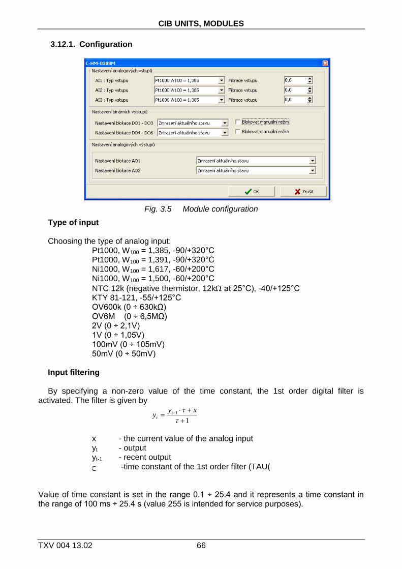
CIB UNITS, MODULES
TXV 004 13.02 66
3.12.1. Configuration
Fig. 3.5 Module configuration
Type of input Choosing the type of analog input:
Pt1000, W100 = 1,385, -90/+320°C Pt1000, W100 = 1,391, -90/+320°C Ni1000, W100 = 1,617, -60/+200°C Ni1000, W100 = 1,500, -60/+200°C
NTC 12k (negative thermistor, 12k at 25°C), -40/+125°C KTY 81-121, -55/+125°C OV600k (0 ÷ 630kΩ) OV6M (0 ÷ 6,5MΩ) 2V (0 ÷ 2,1V) 1V (0 ÷ 1,05V) 100mV (0 ÷ 105mV) 50mV (0 ÷ 50mV)
Input filtering By specifying a non-zero value of the time constant, the 1st order digital filter is
activated. The filter is given by
1
1
xyy t
t
x - the current value of the analog input yt - output yt-1 - recent output time constant of the 1st order filter (TAU) - ح
Value of time constant is set in the range 0.1 ÷ 25.4 and it represents a time constant in the range of 100 ms ÷ 25.4 s (value 255 is intended for service purposes).
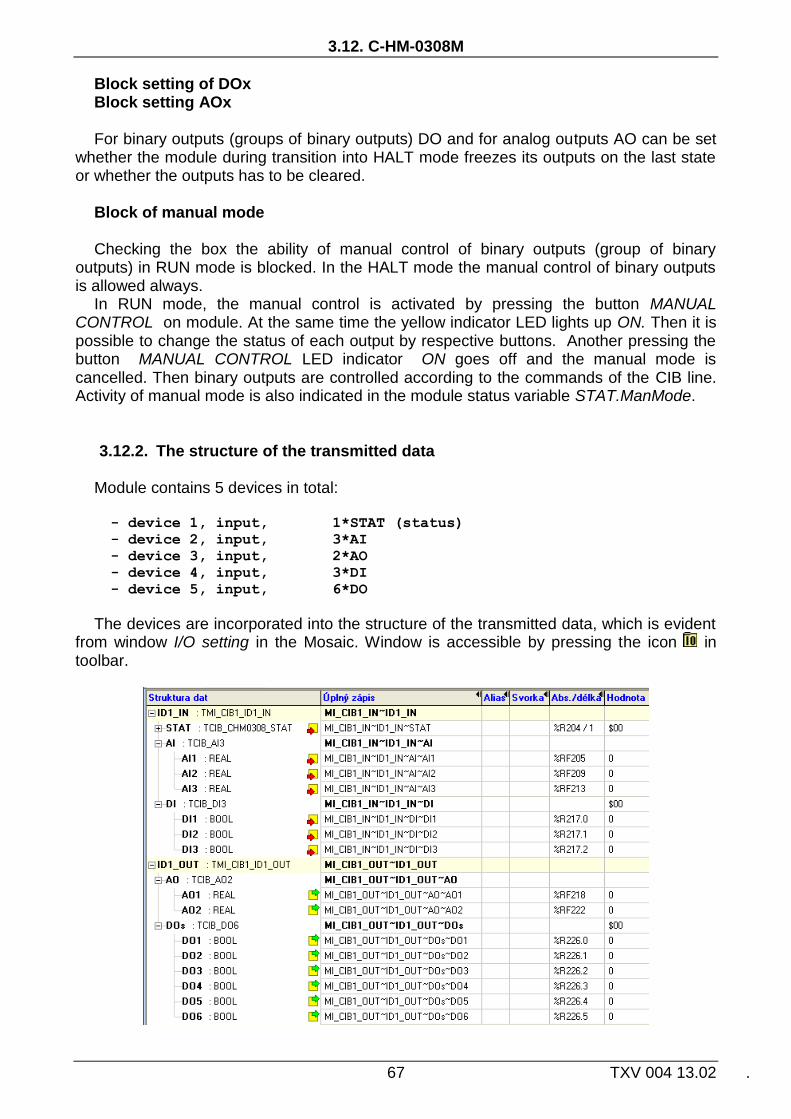
3.12. C-HM-0308M
67 TXV 004 13.02 .
Block setting of DOx Block setting AOx For binary outputs (groups of binary outputs) DO and for analog outputs AO can be set
whether the module during transition into HALT mode freezes its outputs on the last state or whether the outputs has to be cleared.
Block of manual mode Checking the box the ability of manual control of binary outputs (group of binary
outputs) in RUN mode is blocked. In the HALT mode the manual control of binary outputs is allowed always.
In RUN mode, the manual control is activated by pressing the button MANUAL CONTROL on module. At the same time the yellow indicator LED lights up ON. Then it is possible to change the status of each output by respective buttons. Another pressing the button MANUAL CONTROL LED indicator ON goes off and the manual mode is cancelled. Then binary outputs are controlled according to the commands of the CIB line. Activity of manual mode is also indicated in the module status variable STAT.ManMode.
3.12.2. The structure of the transmitted data
Module contains 5 devices in total:
- device 1, input, 1*STAT (status)
- device 2, input, 3*AI
- device 3, input, 2*AO
- device 4, input, 3*DI
- device 5, input, 6*DO
The devices are incorporated into the structure of the transmitted data, which is evident from window I/O setting in the Mosaic. Window is accessible by pressing the icon in toolbar.

CIB UNITS, MODULES
TXV 004 13.02 68
Fig. 3.6 The structure of the transmitted data
Input data
STAT AI DI
STAT - status byte of module (8x type bool)
PowerErr ManMode VLD3 OUF3 VLD2 OUF2 VLD1 OUF1
Bit .7 .6 .5 .4 .3 .2 .1 .0
OUFx - overflow / underflow of analog input measurement AIx VLDx - validity of reading of analog input AIx ManMode - signalling of manual mode of binary outputs. PowerErr - supply voltage drop below the limit for guaranteed switching
of relay outputs DO AIx - value of analog inputs (3x type real) - for temperature sensor temperature [°C]
- for resistor sensor OV600k resistor [k]
- for resistor sensor OV6M resistor [M] - for voltage range voltage [mV] DIx - value of binary inputs (3x type bool) Output data
AO DOs
AOx - value of analog outputs (2x type real) [%] DOx - value of binary outputs (6x type bool)

3.13. C-HM-1113M
69 TXV 004 13.02 .
3.13. C-HM-1113M
Module contains 8 binary inputs for dry contacts, 3 analog inputs for resistor sensors, 2 voltage analog outputs (0÷10V) and 11 relay outputs. Analog inputs are configurable according to the type of sensor, relay outputs allow local manual control buttons on the module. Mechanical design corresponds to the modular design with width of 6M for mounting on the DIN-rail.
Fig. 3. 7 View and connection C-HM-1113M

CIB UNITS, MODULES
TXV 004 13.02 70
Tab. 3.13 Basic parameters C-HM-1113M Binary inputs
Quantity, type 8, NO contacts
Input voltage 10V from internal power supply
Galvanic isolation No
Binary outputs
Quantity 11
Type Switching relay
Switched voltage Max. 250V, min. 5V
Switched current Max. 3A, min. 100mA, DO11 max. 10A
Galvanic isolation Yes, even among groups, with the exception of COM5 and COM6
Current of the common terminal of the group
Max. 10A
Protection against inductive load
External (RC circuit, diode, varistor)
Analog outputs
Quantity 2
Type Active, voltage, 8 bits
Range 0 ÷ 10,5V
Max. output current 10mA
Error of output 2% of full range,
Power supply
Power supply and communication
24 V (27 V) from the CIB
Max. power consumption
160 mA
3.13.1. Configuration
Fig. 3.8 Module configuration
Analog inputs
Quantity 3
Type of convertor Approximation ,12 bit
Range of measurement - resistor - voltage
*)
Pt1000 (-90/+320°C), Ni1000 (-60/+200°C), NTC12k (-40/+125°C), KTY81-121(-55/+125°C)
OV600k (0 ÷ 630kΩ), OV6M (0 ÷ 6,5MΩ), 2V (0 ÷ 2,1V), 1V (0 ÷ 1,05V), 100mV (0 ÷ 105mV), 50mV (0 ÷ 52,5mV)
Error of input 3% of full range, *) Available from version 1.5 of module firmware
Dimensions and weight
Dimensions 90 × 58 × 105mm
Weight 270g
Operating and installation conditions
Operating temperature 0 ÷ +55 °C
Storage temperature -25 ÷ +70 °C
IP degree of protection acc. IEC 529
IP10B
Operating position vertical
Type of operation Continuous
Installation on DIN rail
Connection terminals Screw-type, removable
Cross-section of wires Max. 2,5 mm2

3.13. C-HM-1113M
71 TXV 004 13.02 .
Type of input Choosing the type of analog input:
Pt1000, W100 = 1,385, -90/+320°C Pt1000, W100 = 1,391, -90/+320°C Ni1000, W100 = 1,617, -60/+200°C Ni1000, W100 = 1,500, -60/+200°C
NTC 12k (negative thermistor, 12k at 25°C), -40/+125°C KTY 81-121, -55/+125°C OV600k (0 ÷ 630kΩ) OV6M (0 ÷ 6,5MΩ) 2V (0 ÷ 2,1V) 1V (0 ÷ 1,05V) 100mV (0 ÷ 105mV) 50mV (0 ÷ 50mV)
Input filtering By specifying a non-zero value of the time constant, the 1st order digital filter is
activated. The filter is given by
1
1
xyy t
t
x - the current value of the analog input yt - output yt-1 - recent output time constant of the 1st order filter (TAU) - ح
Value of time constant is set in the range 0.1 ÷ 25.4 and it represents a time constant in the range of 100 ms ÷ 25.4 s (value 255 is intended for service purposes).
Block setting of DOx Block setting AOx For binary outputs (groups of binary outputs) DO and for analog outputs AO can be set
whether the module during transition into HALT mode freezes its outputs on the last state or whether the outputs has to be cleared.
Block of manual mode Checking the box the ability of manual control of binary outputs (group of binary
outputs) in RUN mode is blocked. In the HALT mode the manual control of binary outputs is allowed always.
In RUN mode, the manual control is activated by pressing the button MANUAL CONTROL on module. At the same time the yellow indicator LED lights up ON. Then it is possible to change the status of each output by respective buttons. Another pressing the button MANUAL CONTROL LED indicator ON goes off and the manual mode is cancelled. Then binary outputs are controlled according to the commands of the CIB line. Activity of manual mode is also indicated in the module status variable STAT.ManMode.
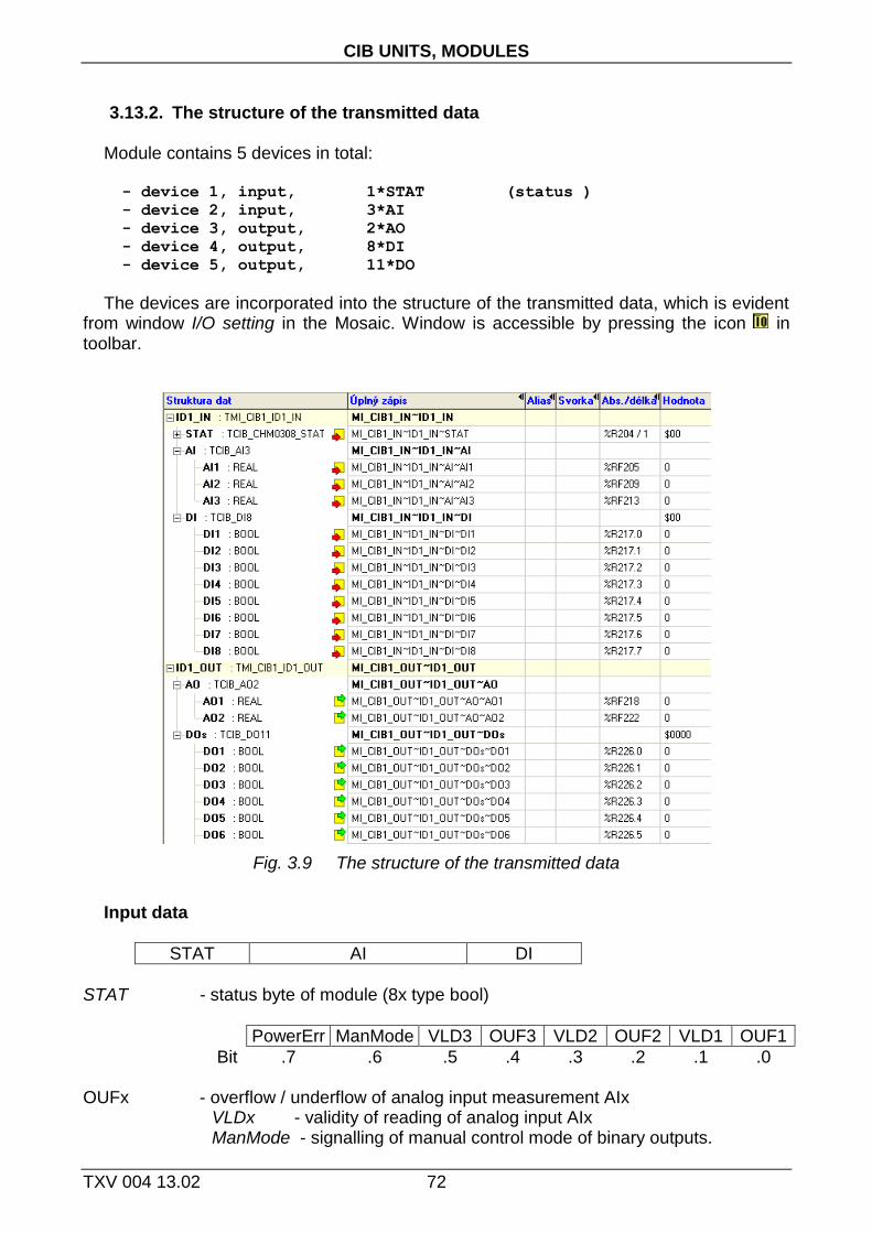
CIB UNITS, MODULES
TXV 004 13.02 72
3.13.2. The structure of the transmitted data
Module contains 5 devices in total:
- device 1, input, 1*STAT (status )
- device 2, input, 3*AI
- device 3, output, 2*AO
- device 4, output, 8*DI
- device 5, output, 11*DO
The devices are incorporated into the structure of the transmitted data, which is evident from window I/O setting in the Mosaic. Window is accessible by pressing the icon in toolbar.
Fig. 3.9 The structure of the transmitted data
Input data
STAT AI DI
STAT - status byte of module (8x type bool)
PowerErr ManMode VLD3 OUF3 VLD2 OUF2 VLD1 OUF1
Bit .7 .6 .5 .4 .3 .2 .1 .0
OUFx - overflow / underflow of analog input measurement AIx VLDx - validity of reading of analog input AIx ManMode - signalling of manual control mode of binary outputs.

3.13. C-HM-1113M
73 TXV 004 13.02 .
PowerErr - supply voltage drop below the limit for guaranteed switching of relay outputs DO
AIx - value of analog inputs (3x type real) [°C] [kΩ] [MΩ] [mV] DIx - value of binary inputs (8x type bool)
Output data
AO DOs
AOx - value of analog outputs (2x type real) [%] DOx - value of binary outputs (11x type bool)

CIB UNITS, MODULES
TXV 004 13.02 74
3.14. C-HM-1121M
Module contains 8 binary inputs for dry contacts, 3 analog inputs for resistor sensors, 2 voltage analog outputs (0÷10V) and 19 relay outputs. Analog inputs are configurable according to the type of sensor, relay outputs allow local manual control buttons on the module. Mechanical design corresponds to the modular design with width of 9M for mounting on the DIN-rail.
Fig. 3. 10 View and connection C-HM-1121M
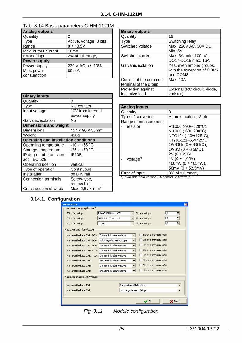
3.14. C-HM-1121M
75 TXV 004 13.02 .
Tab. 3.14 Basic parameters C-HM-1121M Analog outputs
Quantity 2
Type Active, voltage, 8 bits
Range 0 ÷ 10,5V
Max. output current 10mA
Error of input 2% of full range,
Power supply
Power supply 230 V AC, +/- 10%
Max. power consumption
60 mA
Binary inputs
Quantity 8
Type NO contact
Input voltage 10V from internal power supply
Galvanic isolation No
Dimensions and weight
Dimensions 157 × 90 × 58mm
Weight 450g
Operating and installation conditions
Operating temperature -10 ÷ +55 °C
Storage temperature -25 ÷ +70 °C
IP degree of protection acc. IEC 529
IP10B
Operating position vertical
Type of operation Continuous
Installation on DIN rail
Connection terminals Screw-type, removable
Cross-section of wires Max. 2,5 / 4 mm2
3.14.1. Configuration
Fig. 3.11 Module configuration
Binary outputs
Quantity 19
Type Switching relay
Switched voltage Max. 250V AC, 30V DC, Min. 5V
Switched current Max. 3A, min. 100mA, DO17-DO19 max. 16A
Galvanic isolation Yes, even among groups, with the exception of COM7 and COM8
Current of the common terminal of the group
Max. 10A
Protection against inductive load
External (RC circuit, diode, varistor)
Analog inputs
Quantity 3
Type of convertor Approximation ,12 bit
Range of measurement - resistor
- voltage
*)
Pt1000 (-90/+320°C), Ni1000 (-60/+200°C), NTC12k (-40/+125°C), KTY81-121(-55/+125°C)
OV600k (0 ÷ 630kΩ), OV6M (0 ÷ 6,5MΩ), 2V (0 ÷ 2,1V), 1V (0 ÷ 1,05V), 100mV (0 ÷ 105mV), 50mV (0 ÷ 52,5mV)
Error of input 3% of full range, *) Available from version 1.5 of module firmware

CIB UNITS, MODULES
TXV 004 13.02 76
Type of input Choosing the type of analog input:
Pt1000, W100 = 1,385, -90/+320°C Pt1000, W100 = 1,391, -90/+320°C Ni1000, W100 = 1,617, -60/+200°C Ni1000, W100 = 1,500, -60/+200°C
NTC 12k (negative thermistor, 12k at 25°C), -40/+125°C KTY 81-121, -55/+125°C OV600k (0 ÷ 630kΩ) OV6M (0 ÷ 6,5MΩ) 2V (0 ÷ 2,1V) 1V (0 ÷ 1,05V) 100mV (0 ÷ 105mV) 50mV (0 ÷ 50mV)
Input filtering By specifying a non-zero value of the time constant, the 1st order digital filter is
activated. The filter is given by
1
1
xyy t
t
x - the current value of the analog input yt - output yt-1 - recent output time constant of the 1st order filter (TAU) - ح
Value of time constant is set in the range 0.1 ÷ 25.4 and it represents a time constant in the range of 100 ms ÷ 25.4 s (value 255 is intended for service purposes).
Blocking of DOx Blocking of AOx It can be set for binary outputs (groups of binary outputs) DO and for analog outputs AO
if they should stay in their last state or they should be disconnected during transition into HALT mode.
Blocking of manual mode Checking the box the ability of manual control of binary outputs (group of binary
outputs) in RUN mode is blocked. In the HALT mode the manual control of binary outputs is allowed always.
In RUN mode, the manual control is activated by pressing the button MANUAL CONTROL on module. At the same time the yellow indicator LED lights up ON. Then it is possible to change the status of each output by respective buttons. Another pressing the button MANUAL CONTROL LED indicator ON goes off and the manual mode is cancelled. Then binary outputs are controlled according to the commands of the CIB line. Activity of manual mode is also indicated in the module status variable STAT.ManMode.

3.14. C-HM-1121M
77 TXV 004 13.02 .
3.14.2. The structure of the transmitted data
Module contains 5 devices in total:
- device 1, input, 1*STAT (status )
- device 2, input, 3*AI
- device 3, output, 2*AO
- device 4, input, 8*DI
- device 5, output, 19*DO
The devices are incorporated into the structure of the transmitted data, which is evident from window I/O setting in the Mosaic. Window is accessible by pressing the icon in toolbar.
Fig. 3.12 The structure of the transmitted data
Input data
STAT AI DI
STAT - status byte of module (8x type bool)
PowerErr ManMode VLD3 OUF3 VLD2 OUF2 VLD1 OUF1
Bit .7 .6 .5 .4 .3 .2 .1 .0
OUFx - overflow / underflow of analog input measurement VLDx - validity of reading of analog input AIx ManMode - signalling of manual control mode of binary outputs. PowerErr - supply voltage drop below the limit for guaranteed switching
of relay outputs DO AIx - value of analog inputs (3x type real) [°C] [kΩ] [MΩ] [mV] DIx - value of binary inputs (8x type bool)

CIB UNITS, MODULES
TXV 004 13.02 78
Output data
AO DOs
AOx - value of analog outputs (2x type real) [%] DOx - value of binary outputs (19x type bool)

3.15. C-IB-1800M
79 TXV 004 13.02 .
3.15. C-IB-1800M
The module contains a total of 18 binary inputs for potential-free normally open contacts. Each of these inputs can also be configured as an alarm input for security technology. Additionally four inputs can also be used either as the analog input for connection of resistive sensors or as the counter input for counting pulses from meters (standard interface S0 according to IEC 61393 / DIN 43864).
After connecting the module to the CIB line (power connected) the green RUN LED lights still. If the module is served by the CIB (it communicates), green RUN LED flashes regularly. The module can be powered from an external 24V DC source (not to overload CIB line). The module also provides power output 12V DC (supply security detectors etc.).
Mechanical design corresponds to the modular design with width of 4M for mounting on the DIN-rail.
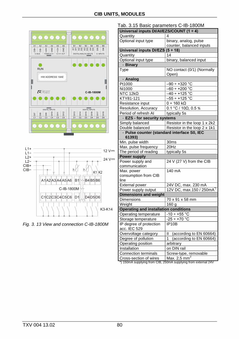
CIB UNITS, MODULES
TXV 004 13.02 80
Tab. 3.15 Basic parameters C-IB-1800M
Fig. 3. 13 View and connection C-IB-1800M
Universal inputs DI/AI/EZS/COUNT (1 ÷ 4)
Quantity 4
Optional input type binary, analog, pulse counter, balanced inputs
Universal inputs DI/EZS (5 ÷ 18)
Quantity 14
Optional input type binary, balanced input
- Binary
Type NO contact (0/1) (Normally Open)
- Analog
Pt1000 –90 ÷ +320 °C
Ni1000 –60 ÷ +200 °C
NTC 12kΩ –40 ÷ +125 °C
KTY81-121 –55 ÷ +125 °C
Resistance input 0 ÷ 160 kΩ
Resolution, Accuracy 0.1 °C / 10Ω, 0.5 %
Period of refresh AI typically 5s
- EZS - for security systems
Simply balanced Resistor in the loop 1 x 2k2
Double balanced Resistor in the loop 2 x 1k1
- Pulse counter (standard interface S0, IEC 61393)
Min. pulse width 30ms
Max. pulse frequency 20Hz
The period of reading typically 5s
Power supply
Power supply and communication
24 V (27 V) from the CIB
Max. power consumption from CIB line
140 mA
External power 24V DC, max. 230 mA
Power supply output 12V DC, max.150 / 250mA*)
Dimensions and weight
Dimensions 70 x 91 x 58 mm
Weight 160 g
Operating and installation conditions
Operating temperature -10 ÷ +55 °C
Storage temperature -25 ÷ +70 °C
IP degree of protection acc. IEC 529
IP10B
Overvoltage category II (according to EN 60664)
Degree of pollution 1 (according to EN 60664)
Operating position arbitrary
Installation on DIN rail
Connection terminals Screw-type, removable
Cross-section of wires Max. 2,5 mm2
*) 150mA supplying from CIB, 250mA supplying from external 24V

3.15. C-IB-1800M
81 TXV 004 13.02 .
Fig. 3. 14 Simply balanced input for security detectors Fig. 3. 15 Double-balanced input for security detectors
3.15.1. Configuration
Fig. 3.16 Module configuration
The input terminals DI/AIx are shared for binary and analog inputs (for digital and
analog equipment).As the input is configured as analog one, it is not possible use it as binary input in the same time. Depending on the configured input (as enabled devices) specific items of configuration dialog are enabled/disabled. Enabling devices see. chap.2.1 Master configuration, check the box Show units, devices

CIB UNITS, MODULES
TXV 004 13.02 82
Balanced input By checking the item, the respective input will be evaluated as a simple balanced binary
alarm input. If the item is not checked, the respective input evaluated as a normal binary input (on/off).
Double balanced input By checking the item, respective input will be evaluated as a double balanced binary
alarm input. If the item is not checked and the input is configured for security systems (balanced input), the respective input evaluated as alarm input with a simple balance.
Delay, evaluation of long press For binary (momentary button) inputs module directly evaluate the short and long
presses on each input. By entering values one can set a delay time after which the activation of digital input DI is signalled as the long press (PRESS). Activating the digital input for period shorter than the entered value will be signalled by as the short press (CLICK). Delay period (Tpress) can be inserted in the range 0.1÷2.5s.
Fig. 3. 17 Evaluation of short / long press
Type of input Choosing the type of analog input:
Pt1000, W100 = 1,385, -90/+320°C Pt1000, W100 = 1,391, -90/+320°C Ni1000, W100 = 1,617, -60/+200°C Ni1000, W100 = 1,500, -60/+200°C
NTC 12k (negative thermistor, 12k at 25°C), -40/+125°C KTY 81-121, -55/+125°C OV160k (0 ÷ 160kΩ) 16-bit pulse counter, S0
Input filtering By specifying a non-zero value of the time constant, the 1st order digital filter is
activated. The filter is given by
1
1
xyy t
t
x - the current value of the analog input

3.15. C-IB-1800M
83 TXV 004 13.02 .
yt - output yt-1 - recent output time constant of the 1st order filter (TAU) - ح
Value of time constant is set in the range 0.1 ÷ 25.4 and it represents a time constant in the range of 100 ms ÷ 25.4 s (value 255 is intended for service purposes).
3.15.1. The structure of the transmitted data
Module contains 6 devices in total:
- device 1, input, 18*DI/EZS
- device 2, input, 1*STAT (status )
- device 3, input, 1*AI (AI1)
- device 4, input, 1*AI (AI2)
- device 5, input, 1*AI (AI3)
- device 6, input, 1*AI (AI4)
The devices are incorporated into the structure of the transmitted data, which is evident from window I/O setting in the Mosaic. Window is accessible by pressing the icon in toolbar.
Fig. 3.18 The structure of the transmitted data
Input data
DIs STAT AI1 AI2 AI3 AI4
DI s.DI - current statuses of binary inputs (18x type bool)
DI18 DI17 ….. DI2 DI1
Bit .17 .16 .1 .0
DIx - Current status of binary input DIx / alarm input x DI s.CLICK - current statuses of binary inputs (18x type bool)
CLICK18 CLICK17 ….. CLICK2 CLICK1

CIB UNITS, MODULES
TXV 004 13.02 84
Bit .17 .16 .1 .0
CLICKx - short pulse (to log. 1) on binary input (button) x DI s.PRESS - long presses on binary inputs (18x type bool)
PRESS18 PRESS17 ….. PRESS2 PRESS1
Bit .17 .16 .1 .0
PRESSx - long pulse (into log. 1) on binary input (button) x DI s.TAMPER - statuses of tamper at balanced inputs (18x type bool)
TAMPER18 TAMPER17 ….. TAMPER2 TAMPER1
Bit .17 .16 .1 .0
TAMPERx - tamper status on balanced input x STAT - status byte of analog inputs (8x type bool)
VLD4 OUF4 VLD3 OUF3 VLD2 OUF2 VLD1 OUF1
Bit .7 .6 .5 .4 .3 .2 .1 .0
OUFx - overflow / underflow of range of analog input AIx VLDx - validity of reading of analog input AIx AI1 - value of analog input AI1/pulse counter 1 (type real) [°C],[kΩ] AI2 - value of analog input AI2/pulse counter 2 (type real) [°C],[kΩ] AI3 - value of analog input AI3/pulse counter 3 (type real) [°C],[kΩ] AI4 - value of analog input AI4/pulse counter 4 (type real) [°C],[kΩ] The value of temperature sensor is transferred in °C (with resolution of
0.1°C), the value of general resistance in range 160kΩ is transferred in kΩ (with resolution of 10Ω). If the input is configured as the 16-bit pulse counter the value corresponds to the counter status (restart the module resets the counter value).

3.16. C-IR-0202S
85 TXV 004 13.02 .
3.16. C-IR-0202S
The module includes one relay output, one analog output (0-10V) and 2 universal inputs. Each of the universal inputs can be used by either the binary input for potential free contacts or as a balanced input for alarm detectors (security systems) or as the analog input for connecting a resistance or temperature sensor.
The mechanical design of the module is designed to be mounted under cover of device (ingress protection of the module IP10B). Signals of the module are available on ribbon cable. Outputs of relay contacts are led out on two separate wires with increased insulation.
signalling green RUN LED is accessible from the side of module opposite to ribbon cable. Connecting on the CIB bus (connection to the power supply) is indicated by permanent lit of the RUN LED. Module operation on the CIB is indicated by regular flashing of the RUN LED.
For sensors Pt1000, Ni1000, KTY81-121, and sensor TC and TZ (thermistor NTC12k) module performs the conversion and linearization of measured values directly to temperature. For other types of resistors (in range 0 to 160 kΩ) the conversion to the temperature has to be done in user program in CPU (module gives the value in kΩ, with resolution 10 Ω).

CIB UNITS, MODULES
TXV 004 13.02 86
Tab. 3.16 Basic parameters C-IR-0202S
Fig. 3. 19 View and connection C-IR-0202S
Universal inputs
Quantity 2
Optional input type Binary, balanced, Pt1000, Ni1000, NTC12kΩ, KTY81-121, resistance 160kΩ
Binary input NO contact (0/1) (Normally Open)
Balanced input for security detectors
Resistance 1x2k2, or 2x1k1
Pt1000 –90 ÷ +320 °C
Ni1000 –60 ÷ +200 °C
NTC 12kΩ –40 ÷ +125 °C
KTY81-121 –55 ÷ +125 °C
Resistance input 0 ÷ 160kΩ
Resolution, Accuracy 0.1 °C / 10Ω, 0.5%
Period of refresh AI typically 5s
Binary relay output
Type, contact material, max. current
normally open contact (NO), Ag-Ni, 5A
Max. switching power 750VA / 90W
Max. switched voltage 277VAC / 30VDC
Analog output
Type, nominal voltage Ujm Voltage, 0 ÷ 10V
Adjustable range 0 ÷ 130% Ujm
Minimal resolution 1%
Power supply
Power supply and communication
24 V (27 V) from the CIB
Nominal/max. power consumption
18 / 25 mA
Galvanic isolation Only output relay contact
Dimensions and weight
Dimensions max. 55 × 26 × 20mm
Weight 7 g
Operating and installation conditions
Operating temperature 0 ÷ +55 °C
Storage temperature -25 ÷ +70 °C
IP degree of protection acc. IEC 529
IP10B
Overvoltage category II (according to EN 60664)
Degree of pollution 1 (according to EN 60664)
Operating position arbitrary
Installation
Type under cover of device
Connecting Ribbon cable 0.15 / 0.5mm2

3.16. C-IR-0202S
87 TXV 004 13.02 .
Fig. 3. 20 Simply balanced input for security detectors Fig. 3. 21 Double-balanced input for security detectors
3.16.1. Configuration
Fig. 3.22 Module configuration
The input terminals DI/AIx are shared for binary and analog inputs (for digital and
analog equipment). As the input is configured as analog one, it is not possible use it as binary input in the same time. Depending on the configured input (as enabled devices) specific items of configuration dialog are enabled/disabled. Enabling devices see. chap. 2.1 Master configuration, check the box Show units, devices
Balanced input By checking the item, the respective input will be evaluated as a simple balanced binary
alarm input. If the item is not checked, the respective input evaluated as a normal binary input (on/off).
Double balanced input

CIB UNITS, MODULES
TXV 004 13.02 88
By checking the item, respective input will be evaluated as a double balanced binary alarm input. If the item is not checked and the input is configured for security systems (balanced input), the respective input evaluated as alarm input with a simple balance.
Type of input Choosing the type of analog input:
Pt1000, W100 = 1,385, -90/+320°C Pt1000, W100 = 1,391, -90/+320°C Ni1000, W100 = 1,617, -60/+200°C Ni1000, W100 = 1,500, -60/+200°C
NTC 12k (negative thermistor, 12k at 25°C), -40/+125°C KTY 81-121, -55/+125°C OV160k (0 ÷ 160kΩ)
Input filtering By specifying a non-zero value of the time constant, the 1st order digital filter is
activated. The filter is given by
1
1
xyy t
t
x - the current value of the analog input yt - output yt-1 - recent output time constant of the 1st order filter (TAU) - ح
Value of time constant is set in the range 0.1 ÷ 25.4 and it represents a time constant in the range of 100 ms ÷ 25.4 s (value 255 is intended for service purposes).
Blocking of DO1 Blocking of AO1 It can be set for binary outputs and for analog output AO1 if they should stay in their last
state or they should be disconnected during transition into HALT mode.
3.16.2. The structure of the transmitted data
Module contains 5 devices in total:
- device 1, input/output,2*DI,EZS/1*DO
- device 2, output, 1*AO
- device 3, input, 1*STAT (status AIx)
- device 4, input, 1*AI (input AI1)
- device 5, input, 1*AI (input AI2)
The devices are incorporated into the structure of the transmitted data, which is evident from window I/O setting in the Mosaic. Window is accessible by pressing the icon in toolbar.
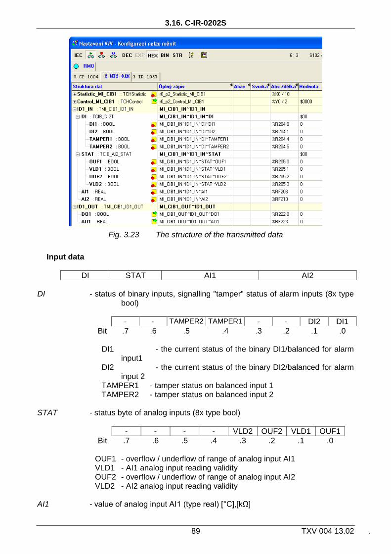
3.16. C-IR-0202S
89 TXV 004 13.02 .
Fig. 3.23 The structure of the transmitted data
Input data
DI STAT AI1 AI2
DI - status of binary inputs, signalling "tamper" status of alarm inputs (8x type
bool)
- - TAMPER2 TAMPER1 - - DI2 DI1
Bit .7 .6 .5 .4 .3 .2 .1 .0
DI1 - the current status of the binary DI1/balanced for alarm input1
DI2 - the current status of the binary DI2/balanced for alarm input 2
TAMPER1 - tamper status on balanced input 1 TAMPER2 - tamper status on balanced input 2 STAT - status byte of analog inputs (8x type bool)
- - - - VLD2 OUF2 VLD1 OUF1
Bit .7 .6 .5 .4 .3 .2 .1 .0
OUF1 - overflow / underflow of range of analog input AI1 VLD1 - AI1 analog input reading validity OUF2 - overflow / underflow of range of analog input AI2 VLD2 - AI2 analog input reading validity AI1 - value of analog input AI1 (type real) [°C],[kΩ]

CIB UNITS, MODULES
TXV 004 13.02 90
AI2 - value of analog input AI2 (type real) [°C],[kΩ] The value of temperature sensor is transferred in °C (with resolution of
0.1°C), the value of general resistance in range 160kΩ is transferred in kΩ (with resolution of 10Ω).
Output data
DO1 AO1
DO1 - status of binary output (type bool) AO1 - value of analog output (type real) [0-100%]

3.17. C-IR-0203M
91 TXV 004 13.02 .
3.17. C-IR-0203M
The module includes two relay outputs, one analog output (PWM/0-10V) and 2 universal inputs. Each of the universal inputs can be used by either the binary input for potential free contacts or as a balanced input for alarm detectors (security systems) or as the analog input for resistance or temperature sensors.
Analog inputs are configurable according to the type of sensor. Mode of analog / PWM output is configurable by the switch on the module. Relay outputs allow local manual control by buttons on the module. Mechanical design corresponds to the modular design with width of 1.5M for mounting on the DIN-rail.
There is signalling green RUN LED on top of the module. Connecting on the CIB bus (connection to the power supply) is indicated by permanent lit of the RUN LED. Module operation on the CIB is indicated by regular flashing of the RUN LED.

CIB UNITS, MODULES
TXV 004 13.02 92
Tab. 3.17 Basic parameters C-IR-0203S
Fig. 3. 24 View and connection C-IR-0203M
Universal inputs
Quantity 2
Optional input type Binary (button), balanced, Pt1000, Ni1000, NTC12kΩ, KTY81-121, resistance 160kΩ
Binary input NO contact (0/1) (Normally Open)
Balanced input for security detectors
Resistance 1x2k2, or 2x1k1
Pt1000 –90 ÷ +320 °C
Ni1000 –60 ÷ +200 °C
NTC 12kΩ –40 ÷ +125 °C
KTY81-121 –55 ÷ +125 °C
Resistance input 0 ÷ 160kΩ
Resolution, Accuracy 0.1 °C / 10Ω, 0.5 %
Period of refresh AI typically 5s
Binary relay output
Type changeover contacts
Max. switched voltage 300V AC / 300V DC (min.5V)
Switched current max. 16A/10A NO/NC (min.100mA)
Max. switching power 4000VA / 384W
Analog output
Mode Analog PWM Nominal voltage/amplitude 10V ±2% 10 ÷ 24V ±2%
The repetition frequency - 100 ÷ 2000Hz
Adjustable range 0 ÷ 100% Ujm
Minimal resolution 1%
Power supply
Power supply and communication
24 V (27 V) from the CIB
Max. power consumption
60 mA
Galvanic isolation Only output relay contact
Dimensions and weight
Dimensions 105 × 90 × 22mm
Weight 95 g
Operating and installation conditions
Operating temperature 0 ÷ +55 °C
Storage temperature -25 ÷ +70 °C
IP degree of protection acc. IEC 529
IP10B
Overvoltage category II (according to EN 60664)
Degree of pollution 1 (according to EN 60664)
Operating position vertical
Installation
Connection terminals Screw-type
Cross-section of wires Max. 2,5 mm2

3.17. C-IR-0203M
93 TXV 004 13.02 .
Fig. 3. 25 Simply balanced input for security detectors Fig. 3. 26 Double-balanced input for security detectors
3.17.1. Configuration
Fig. 3.27 Module configuration
The input terminals DI/AIx are shared for binary and analog inputs (for digital and
analog equipment). As the input is configured as analog one, it is not possible use it as binary input in the same time. Depending on the configured input (as enabled devices) specific items of configuration dialog are enabled/disabled. Enabling devices see. chap. 2.1 Master configuration, check the box Show units, devices
The analog output can be operated in either an analog voltage output, or PWM output mode. The PWM mode is set by HW switch on the front panel of the module (always switch the both independent switches).Switch status is indicated in the status variable of moduleSTAT.PWM.
Balanced input By checking the item, the respective input will be evaluated as a simple balanced binary
alarm input. If the item is not checked, the respective input evaluated as a normal binary input (on/off).

CIB UNITS, MODULES
TXV 004 13.02 94
Double balanced input By checking the item, respective input will be evaluated as a double balanced binary
alarm input. If the item is not checked and the input is configured for security systems (balanced input), the respective input evaluated as alarm input with a simple balance.
Delay, evaluation of long press For binary (momentary button) inputs module directly evaluate the short and long
presses on each input. By entering values one can set a delay time after which the activation of digital input DI is signalled as the long press (PRESS).Activating the digital input for period shorter than the entered value will be signalled as the short press (CLICK).Delay period (Tpress) can be inserted in the range 0.1÷2.5s.
Fig. 3. 28 Evaluation of short / long press
Type of input Choosing the type of analog input:
Pt1000, W100 = 1,385, -90/+320°C Pt1000, W100 = 1,391, -90/+320°C Ni1000, W100 = 1,617, -60/+200°C Ni1000, W100 = 1,500, -60/+200°C
NTC 12k (negative thermistor, 12k at 25°C), -40/+125°C KTY 81-121, -55/+125°C OV160k (0 ÷ 160kΩ)
Input filtering By specifying a non-zero value of the time constant, the 1st order digital filter is
activated. The filter is given by
1
1
xyy t
t
x - the current value of the analog input yt - output yt-1 - recent output time constant of the 1st order filter (TAU) - ح
Value of time constant is set in the range 0.1 ÷ 25.4 and it represents a time constant in the range of 100 ms ÷ 25.4 s (value 255 is intended for service purposes).

3.17. C-IR-0203M
95 TXV 004 13.02 .
Blocking of DO It can be set for binary outputs if they should stay in their last state or they should be
disconnected during transition into HALT mode. Blocking of manual mode The ability of manual control of specific binary outputs in the RUN mode is blocked by
checking the box. In the HALT mode the manual control of LED outputs is allowed always. In RUN mode, the manual control is activated by pressing the button MC (Manual
Control) on module. At the same time the yellow indicator LED MC lights up . Then it is possible to change the status of each output by respective buttons. Another pressing the button MANUAL CONTROL LED indicator MC goes off and the manual mode is cancelled. Then binary outputs are controlled according to the commands of the CIB line. Activity of manual mode is also indicated in the module status variable STAT.MAN.
Setting of PWM output The analog output will work in PWM mode by setting the switch into position PWM .For
this output the PWM frequency can be set in range of 100Hz to 2kHz and nominal voltage level in range of 10V to 24V.
The analog output will work in voltage output mode 0÷10V, if the switch will be set into the position 0-10V.
3.17.2. The structure of the transmitted data
Module contains 6 devices in total: - device 1, input, 2*DI/EZS
- device 2, output, 2*DO
- device 3, input, 1*STAT (status AIx)
- device 4, input, 1*AI (input AI1)
- device 5, input, 1*AI (input AI2)
- device 6, output, 1*AO (output AO/PWM)
The devices are incorporated into the structure of the transmitted data, which is evident from window I/O setting in the Mosaic. Window is accessible by pressing the icon in toolbar.

CIB UNITS, MODULES
TXV 004 13.02 96
Fig. 3.29 The structure of the transmitted data
Input data
DI STAT AI1 AI2
DI - status of binary inputs, signalling "tamper" status of alarm inputs (8x type
bool)
TAMPER2 TAMPER1 PRESS2 PRESS1 CLICK2 CLICK1 DI2 DI1
Bit .7 .6 .5 .4 .3 .2 .1 .0
DIx - Current status of binary input DIx / alarm input x CLICKx - short pulse (to log. 1) on binary input (button) x PRESSx - long pulse (into log. 1) on binary input (button) x TAMPERx - tamper status on balanced input x STAT - status byte of analog inputs (8x type bool)
MAN PWM - - VLD2 OUF2 VLD1 OUF1
Bit .7 .6 .5 .4 .3 .2 .1 .0
OUF1 - overflow / underflow of range of analog input AI1 VLD1 - AI1 analog input reading validity OUF2 - overflow / underflow of range of analog input AI2 VLD2 - AI2 analog input reading validity PWM - state of HW switch of mode of AO1 = 0 - switch in position 0-10V (analog output) = 1 - switch in position PWM (PWM output) MAN - signalling of manual mode of relay outputs.

3.17. C-IR-0203M
97 TXV 004 13.02 .
AI1 - value of analog input AI1 (type real) [°C],[kΩ] AI2 - value of analog input AI2 (type real) [°C],[kΩ] The value of temperature sensor is transferred in °C (with resolution of
0.1°C), the value of general resistance in range 160kΩ is transferred in kΩ (with resolution of 10Ω).
Output data
DOs AO1
DOx - value of binary outputs (8x type bool)
- - - - - - DO2 DO1
Bit .7 .6 .5 .4 .3 .2 .1 .0
DO1 - value of binary output DO1 DO2 - value of binary output DO2 AO1 - value of analog/PWM output (type real) [0÷100%]

CIB UNITS, MODULES
TXV 004 13.02 98
3.18. C-IT-0100H-A
Module temperature sensor in the metal head is designed to temperature measurement in the immersion tube. It contains 2 temperature sensors. The first one is located in the end of the metal stem (main sensor) and is used primary for temperature measurement. The second sensor is placed in the metal head (auxiliary sensor) and is intended for information about the operating temperature of the module head.
After removing the cap of the head CIB connection terminals and signalling RUN LED are accessible. Connecting on the CIB bus (connection to the power supply) is indicated by permanent lit of the RUN LED. Module operation on the CIB is indicated by regular flashing of the RUN LED.
Tab. 3.18 Basic parameters C-IT-0100H-A
CIB
-
CIB
+
Fig. 3. 30 View and connection example C-IT-0100H-A
Temperature inputs
Quantity 2
Sensor type in the stem Pt1000, W100 = 1,385
Range –90 ÷ +320 °C
Resolution 0.1 °C
Accuracy 0.5 °C
Temperature settling time
30 min.
Sensor type in the head Thermistor NTC 12k
Power supply
Power supply and communication
24 V (27 V) from the CIB
Nominal power consumption
8 mA
Galvanic isolation No
Dimensions and weight
Dimensions 90 × 71 × 200mm
Length of the stem 125 mm
Weight 220 g
Operating and installation conditions
Operating temperature -25 ÷ +70 °C
Storage temperature -25 ÷ +80 °C
IP degree of protection acc. IEC 529
IP 54
Overvoltage category EN 60664
II
Degree of pollution EN 60664
1
Operating position arbitrary
Installation
Connecting screw type terminals
Cross-section of wires max. 1,0 mm2

3.18. C-IT-0100H-A
99 TXV 004 13.02 .
3.18.1. Configuration
Fig. 3.31 Module configuration
Temperature offset Correction offset of thermometer, which will be added on the measured temperature.
3.18.2. The structure of the transmitted data
Module contains 3 devices in total:
- device 1, input, 1*STAT (status )
- device 2, input, 1*AI (thermometer in the stem)
- device 3, input, 1*AI (thermometer in the head)
The devices are incorporated into the structure of the transmitted data, which is evident
from window I/O setting in the Mosaic. Window is accessible by pressing the icon in toolbar.
Fig. 3.32 The structure of the transmitted data

CIB UNITS, MODULES
TXV 004 13.02 100
Input data
STAT mTHERM hTHERM
STAT - status byte (8x type bool)
- - - - hVLD hOUF mVLD mOUF
Bit .7 .6 .5 .4 .3 .2 .1 .0
mOUF - overflow/underflow of the range of primary temperature sensor mVLD - validity of the reading of primary temperature sensor hOUF - overflow/underflow of the range of auxiliary temperature sensor hVLD - validity of the reading of auxiliary temperature sensor mTHERM - temperature of primary sensor in the stem (type real) [°C]
hTHERM - temperature of primary sensor, in the head (type real) [°C]

3.19. C-IT-0100H-P
101 TXV 004 13.02 .
3.19. C-IT-0100H-P
Module temperature sensor in the plastic head (with higher ingress protection - IP) is designed to temperature measurement in the immersion tube. It contains 2 temperature sensors. The first one is located in the end of the metal stem (primary sensor) and is used primary for temperature measurement. The second sensor is placed in the plastic head (auxiliary sensor) and is intended for information about the operating temperature of the module head.
After removing the cap of the head CIB connection terminals and signalling RUN LED are accessible. Connecting on the CIB bus (connection to the power supply) is indicated by permanent lit of the RUN LED. Module operation on the CIB is indicated by regular flashing of the RUN LED.
Tab. 3.19 Basic parameters C-IT-0100H-P
CIB
-
CIB
+
Fig. 3. 33 View and connection example C-IT-0100H-P
Temperature inputs
Quantity 2
Sensor type in the stem Pt1000, W100 = 1,385
Range –90 ÷ +320 °C
Resolution 0.1°C
Accuracy 0.5 °C
Temperature settling time
30 min.
Sensor type in the head Thermistor NTC 12k
Power supply
Power supply and communication
24 V (27 V) from the CIB
Nominal power consumption
8 mA
Galvanic isolation No
Dimensions and weight
Dimensions 90 × 66 × 155mm
Length of the stem 115 mm
Weight 130 g
Operating and installation conditions
Operating temperature -25 ÷ +70 °C
Storage temperature -25 ÷ +80 °C
IP degree of protection acc. IEC 529
IP 65
Overvoltage category EN 60664
II
Degree of pollution EN 60664
1
Operating position arbitrary
Installation
Connecting Push-in terminals,
Cross-section of wires max. 1,0 mm2

CIB UNITS, MODULES
TXV 004 13.02 102
3.19.1. Configuration
Fig. 3.34 Module configuration
Temperature offset Correction offset of thermometer, which will be added on the measured temperature.
3.19.2. The structure of the transmitted data
Module contains 3 devices in total:
- device 1, input, 1*STAT (status )
- device 2, input, 1*AI (thermometer in the stem)
- device 3, input, 1*AI (thermometer in the head)
The devices are incorporated into the structure of the transmitted data, which is evident
from window I/O setting in the Mosaic. Window is accessible by pressing the icon in toolbar.
Fig. 3.35 The structure of the transmitted data

3.19. C-IT-0100H-P
103 TXV 004 13.02 .
Input data
STAT mTHERM hTHERM
STAT - status byte (8x type bool)
- - - - hVLD hOUF mVLD mOUF
Bit .7 .6 .5 .4 .3 .2 .1 .0
mOUF - overflow/underflow of the range of primary temperature sensor mVLD - validity of the reading of primary temperature sensor hOUF - overflow/underflow of the range of auxiliary temperature sensor hVLD - validity of the reading of auxiliary temperature sensor mTHERM - temperature of primary sensor in the stem (type real) [°C]
hTHERM - temperature of primary sensor, in the head (type real) [°C]

CIB UNITS, MODULES
TXV 004 13.02 104
3.20. C-IT-0200I
Module contains 2 analog inputs and one internal temperature sensor. Each analog input can be configured independently for temperature sensors, thermocouples, resistors, voltage or current.
Module is designed into the plastic box with the higher ingress protection IP65.
Tab. 3.20 Basic parameters C-IT-0200I
Fig. 3.36 View C-IT-0200I
Power supply
Power supply and communication
24 V (27 V) from the CIB
Max. power consumption
15mA, 60mA (at powering the current loops)
Galvanic isolation No
Dimensions and weight
Dimensions 125 × 100 × 38mm
Weight 120 g
Operating and installation conditions
Operating temperature -10 ÷ +55 °C
Storage temperature -25 ÷ +70 °C
IP degree of protection acc. IEC 529
IP65
Operating position arbitrary
Installation
Type wall mounting
Connecting Push-in terminals,
Cross-section of wires 0,14 ÷ 1,5 mm2
Type of analog input has to be selected in the module configuration in programming environment and by setting of configuration jumpers on the module see following figures.
Analog inputs
Quantity 2
Type of convertor Sigma-delta, 16 bits
Range of measurement - Resistor - Voltage - Current
- Thermocouples
Pt1000 (-90/+320°C), Ni1000 (-60/+200°C), NTC12k/25°C(-40/+125°C), KTY81-121 (-55/+125°C), OV200k (0 ÷ 200kΩ), 0÷10V, 0÷5V, ±2V, ±1V, High Impedance ±1V, High Impedance ±100mV, 0÷20mA, 4÷20mA, type J (-210/+1200°C), type K (-200/+1372°C), type R (-50/+1768°C), type S (-50/+1768°C), type T (+200/+400°C), type B (+250/+1820°C), type N (-200/+1300°C)
Input impedance - RTD, NTC, OV - Voltage ranges - Thermocouples, High
impedance voltage ranges
- Current ranges
4.7kΩ 54.6 kΩ 4MΩ 50Ω
Measurement error < 2% < 5% (for OV200k)
1)
Thermocouple cold junction compensation
Yes ( excluding type B)
Additive error due compensation cold junction
<3% of range of internal thermometer
Internal thermometer
Type NTC12k / 25°C
Range -20 ÷ +80°C
Measurement error < 4% 1)
The measurement error rises for resistors higher than 50kΩ.
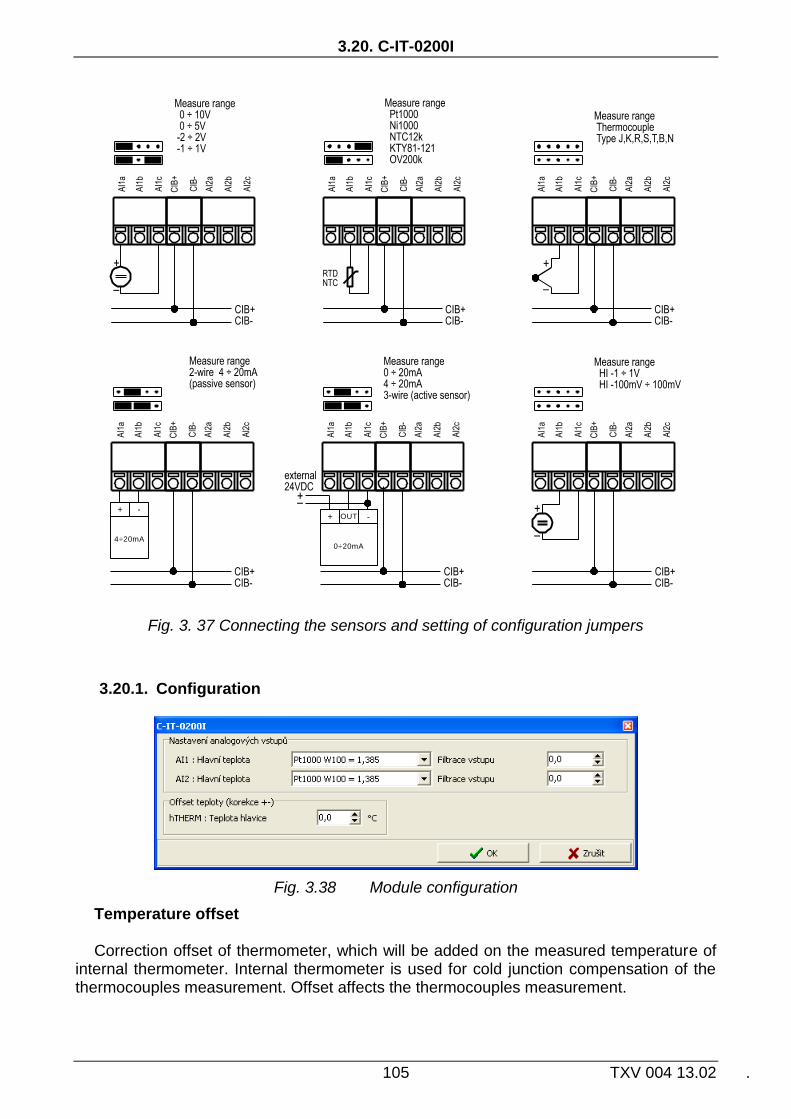
3.20. C-IT-0200I
105 TXV 004 13.02 .
4÷20mA
+ -
0÷20mA
+ -OUT
Fig. 3. 37 Connecting the sensors and setting of configuration jumpers
3.20.1. Configuration
Fig. 3.38 Module configuration
Temperature offset Correction offset of thermometer, which will be added on the measured temperature of
internal thermometer. Internal thermometer is used for cold junction compensation of the thermocouples measurement. Offset affects the thermocouples measurement.

CIB UNITS, MODULES
TXV 004 13.02 106
Setting analog inputs Choosing the type of analog input:
Pt1000, W100 = 1,385, -90/+320°C Pt1000, W100 = 1,391, -90/+320°C Ni1000, W100 = 1,617, -60/+200°C Ni1000, W100 = 1,500, -60/+200°C
NTC 12k (negative thermistor, 12k at 25°C), -40/+125°C KTY 81-121, -55/+125°C OV200k (0 ÷ 200kΩ) 0 ÷ 10V 0 ÷ 5V ±2V ±1V HI ±1V (Voltage range ±1V, High impedance inputs) HI ±100mV (Voltage range ±100mV, High impedance inputs) 0 ÷ 20mA 4 ÷ 20mA
Input filtering By specifying a non-zero value of the time constant, the 1st order digital filter is
activated. The filter is given by
1
1
xyy t
t
x - the current value of the analog input yt - output yt-1 - recent output time constant of the 1st order filter (TAU) - ح
Value of time constant is set in the range 0.1 ÷ 25.4 and it represents a time constant in the range of 100 ms ÷ 25.4 s (value 255 is intended for service purposes).
3.20.2. The structure of the transmitted data
Module contains 4 devices total, each of them can be activated/deactivated:
- device 1, input, 1*STAT (status of analog inputs)
- device 2, input, 1*AI (input AI1)
- device 3, input, 1*AI (input AI2)
- device 4, input, 1*AI (internal thermometer)
The devices are incorporated into the structure of the transmitted data, which is evident
from window I/O setting in the Mosaic. Window is accessible by pressing the icon in toolbar.

3.20. C-IT-0200I
107 TXV 004 13.02 .
Fig. 3.39 The structure of the transmitted data
Input data
STAT AI1 AI2 hTHERM
STAT - status byte (8x type bool)
- - hVLD hOUF VLD2 OUF2 VLD1 OUF1
Bit .7 .6 .5 .4 .3 .2 .1 .0
OUF1 - overflow / underflow of range of analog input AI1 VLD1 - AI1 analog input reading validity OUF2 - overflow / underflow of range of analog input AI2 VLD2 - AI2 analog input reading validity hOUF - overflow/underflow of the range of internal auxiliary temperature
sensor hVLD - validity of the reading of internal auxiliary temperature sensor AI1 - value of analog input AI1 (type real) [°C], [kΩ], [mV], [mA] AI2 - value of analog input AI2 (type real) [°C], [kΩ], [mV], [mA]
The value of temperature sensors is converted and transferred in °C, for
general resistor range of 200kΩ the value is converted and transferred in kΩ (with resolution of 10Ω). For voltage ranges the value is transferred in mV and for current ranges it is transferred in mA.
hTHERM - temperature of auxiliary internal sensor (type real) [°C]

CIB UNITS, MODULES
TXV 004 13.02 108
3.21. C-IT-0200R
Module of temperature sensor is designed for measuring the temperature in the interior. It contains 2 temperature sensors. One sensor in the module is permanently connected and represents internal thermometer. The input for second sensor is led out on the terminal and the stand alone external temperature sensor can be connected..
After removing the plastic cover the RUN LED indicator and the terminals are accessible (for connection to the CIB bus and for an external temperature sensor).Connecting on the CIB bus (connection to the power supply) is indicated by permanent lit of the RUN LED. Module operation on the CIB is indicated by regular flashing of the RUN LED.
Module is designed for Time and Element designs of ABB production. For actual offer of designs see the catalogue of Teco
Tab. 3.21 Basic parameters C-IT-0200R
CIB+ CIB+
CIB- CIB-
TH
ER
M
TH
ER
MC
IB-
CIB
-C
IB+
CIB
+
external temperature sensor
C-IT-0200R-xxx
Fig. 3. 40 View and connection example C-IT-0200R
65) Dimensions according the specifics of used design. The height 18 mm is only the height above the level of the plastic flush installation box. Height of the bottom part located in the flush installation box is 13 mm.
Temperature inputs
Quantity 2
Sensor type Thermistor NTC 12k
External sensor type Thermistor NTC 12k
Range –20 ÷ +80 °C
Resolution 0.1 °C
Accuracy 0.6 °C
Temperature settling time
60 min.
Power supply
Power supply and communication
24 V (27 V) from the CIB
Nominal power consumption
15 mA
Galvanic isolation No
Dimensions and weight
Dimensions1)
89 × 87 × 18mm
Weight 80 g
Operating and installation conditions
Operating temperature 0 ÷ +55 °C
Storage temperature -25 ÷ +70 °C
IP degree of protection acc. IEC 529
IP 10B
Overvoltage category EN 60664
II
Degree of pollution EN 60664
1
Operating position vertical
Installation into the flush box
Connecting screw type terminals
Cross-section of wires max. 1,0 mm2

3.21. C-IT-0200R
109 TXV 004 13.02 .
3.21.1. Configuration
Fig. 3.41 Module configuration
Temperature offset Correction offset of thermometer, which will be added on the measured temperature.
3.21.2. The structure of the transmitted data
Module contains 3 devices in total:
- device 1, input, 1*STAT (status )
- device 2, input, 1*AI (internal thermometer)
- device 3, input, 1*AI (external thermometer)
The devices are incorporated into the structure of the transmitted data, which is evident
from window I/O setting in the Mosaic. Window is accessible by pressing the icon in toolbar.
Fig. 3.42 The structure of the transmitted data
Input data
STAT iTHERM eTHERM

CIB UNITS, MODULES
TXV 004 13.02 110
STAT - status byte (8x type bool)
- - - - eVLD eOUF iVLD iOUF
Bit .7 .6 .5 .4 .3 .2 .1 .0
iOUF - overflow/underflow of the range of internal temperature sensor iVLD - validity of the reading of internal temperature sensor eOUFx - overflow/underflow of the range of external temperature
sensor eVLD - validity of the reading of external temperature sensor iTHERM - temperature of internal sensor (type real) [°C]
eTHERM - temperature of external sensor (type real) [°C]

3.22. C-IT-0200S
111 TXV 004 13.02 .
3.22. C-IT-0200S
Module contains 2 universal inputs. Each of the universal inputs can be used either as the binary input for potential free contacts or as a balanced input for alarm detectors (security systems) or as the analog input for connecting a resistance or temperature sensor.
The mechanical design of the module is designed to be mounted under cover of device (ingress protection of the module IP10B). Signals of the module are available on ribbon cable.
signalling green RUN LED is accessible from the side of module opposite to ribbon cable. Connecting on the CIB bus (connection to the power supply) is indicated by permanent lit of the RUN LED. Module operation on the CIB is indicated by regular flashing of the RUN LED.
For sensors Pt1000, Ni1000, KTY81-121, and sensor TC and TZ (thermistor NTC12k) module performs the conversion and linearization of measured values directly to temperature. For other types of resistors (in range 0 to 160 kΩ) the conversion to the temperature has to be done in user program in CPU (module gives the value in kΩ, with resolution 10 Ω).

CIB UNITS, MODULES
TXV 004 13.02 112
Tab. 3.22 Basic parameters C-IT-0200S
Fig. 3. 43 View and connection C-IT-0200S
Universal inputs
Quantity 2
Optional types of inputs Binary, balanced, Pt1000, Ni1000, NTC12kΩ, KTY81-121, resistance 160kΩ
Binary input NO contact (0/1) (Normally Open)
Balanced input for security detectors
Resistance 1x2k2, or 2x1k1
Pt1000 –90 ÷ +320 °C
Ni1000 –60 ÷ +200 °C
NTC 12kΩ –40 ÷ +125 °C
KTY81-121 –55 ÷ +125 °C
Resistance input 0 ÷ 160kΩ
Resolution 0.1 °C / 10Ω
Accuracy 0,5 %
Period of refresh AI typically 5s
Power supply
Power supply and communication
24 V (27 V) from the CIB
Nominal power consumption
10 mA
Max. power consumption
12 mA
Galvanic isolation No
Dimensions and weight
Dimensions max. 55 × 26 × 16mm
Weight 3 g
Operating and installation conditions
Operating temperature 0 ÷ +55 °C
Storage temperature -25 ÷ +70 °C
IP degree of protection acc. IEC 529
IP10B
Overvoltage category II (according to EN 60664)
Degree of pollution 1 (according to EN 60664)
Operating position Arbitrary
Installation
Type under cover of device
Connecting Ribbon cable 0.15 mm2

3.22. C-IT-0200S
113 TXV 004 13.02 .
Fig. 3. 44 Simply balanced input for security detectors Fig. 3. 45 Double-balanced input for security detectors
3.22.1. Configuration
Fig. 3.46 Module configuration
The input terminals DI/AIx are shared for binary and analog inputs (for digital and
analog equipment).As the input is configured as analog one, it is not possible use it as binary input in the same time. Depending on the configured input (as enabled devices) specific items of configuration dialog are enabled/disabled. Enabling devices see. chap.2.1 Master configuration, check the box Show units, devices
Balanced input By checking the item, the respective input will be evaluated as a simple balanced binary
alarm input. If the item is not checked, the respective input evaluated as a normal binary input (on/off).
Double balanced input By checking the item, respective input will be evaluated as a double balanced binary
alarm input. If the item is not checked and the input is configured for security systems (balanced input), the respective input evaluated as alarm input with a simple balance.
Type of input Choosing the type of analog input:
Pt1000, W100 = 1,385, -90/+320°C Pt1000, W100 = 1,391, -90/+320°C

CIB UNITS, MODULES
TXV 004 13.02 114
Ni1000, W100 = 1,617, -60/+200°C Ni1000, W100 = 1,500, -60/+200°C
NTC 12k (negative thermistor, 12k at 25°C), -40/+125°C KTY 81-121, -55/+125°C OV160k (0 ÷ 160kΩ)
Input filtering
By specifying a non-zero value of the time constant, the 1st order digital filter is activated. The filter is given by
1
1
xyy t
t
x - the current value of the analog input yt - output yt-1 - recent output time constant of the 1st order filter (TAU) - ح
Value of time constant is set in the range 0.1 ÷ 25.4 and it represents a time constant in the range of 100 ms ÷ 25.4 s (value 255 is intended for service purposes).
3.22.2. The structure of the transmitted data
Module contains 4 devices in total: - device 1, input, 2*DI/EZS
- device 2, input, 1*STAT (status AIx)
- device 3, input, 1*AI (input AI1)
- device 4, input, 1*AI (input AI2)
The devices are incorporated into the structure of the transmitted data, which is evident from window I/O setting in the Mosaic. Window is accessible by pressing the icon in toolbar.

3.22. C-IT-0200S
115 TXV 004 13.02 .
Fig. 3.47 The structure of the transmitted data
Input data
DI STAT AI1 AI2
DI - status of binary inputs, signalling "tamper" status of alarm inputs (8x type
bool)
- - TAMPER2 TAMPER1 - - DI2 DI1
Bit .7 .6 .5 .4 .3 .2 .1 .0
DI1 - the current status of the binary DI1/balanced for alarm input1
DI2 - the current status of the binary DI2/balanced for alarm input 2
TAMPER1 - tamper status on balanced input 1 TAMPER2 - tamper status on balanced input 2 STAT - status byte of analog inputs (8x type bool)
- - - - VLD2 OUF2 VLD1 OUF1
Bit .7 .6 .5 .4 .3 .2 .1 .0
OUF1 - overflow / underflow of range of analog input AI1 VLD1 - AI1 analog input reading validity OUF2 - overflow / underflow of range of analog input AI2 VLD2 - AI2 analog input reading validity AI1 - value of analog input AI1 (type real) [°C],[kΩ] AI2 - value of analog input AI2 (type real) [°C],[kΩ] The value of temperature sensor is transferred in °C (with resolution of
0.1°C), the value of general resistance in range 160kΩ is transferred in kΩ (with resolution of 10Ω).

CIB UNITS, MODULES
TXV 004 13.02 116
3.23. C-IT-0504S
Module contains 5 universal inputs and 4 analog outputs (0-10V). Each of the universal inputs can be used either as the binary input for potential free contacts or as a balanced input for alarm detectors (security systems) or as the analog input for connecting a resistance or temperature sensor. Inputs can be configured into two groups, 4+1.
The mechanical design of the module is designed to be mounted under cover of device (ingress protection of the module IP10B). Signals of the module are available on ribbon cable.
The green LED indicating the RUN mode is available from the side of the module next to the connector. Connecting on the CIB bus (connection to the power supply) is indicated by permanent lit of the RUN LED. Module operation on the CIB is indicated by regular flashing of the RUN LED.
For sensors Pt1000, Ni1000, KTY81-121, and sensor TC and TZ (thermistor NTC12k) module performs the conversion and linearization of measured values directly to temperature. For other types of resistors (in range 0 to 160 kΩ) the conversion to the temperature has to be done in user program in CPU (module gives the value in kΩ, with resolution 10 Ω).

3.23. C-IT-0504S
117 TXV 004 13.02 .
Tab. 3.23 Basic parameters C-IT-0504S
Fig. 3. 48 View and connection C-IT-0504S
Universal inputs
Quantity 5
Optional types of inputs Binary, balanced, Pt1000, Ni1000, NTC12kΩ, KTY81-121, resistance 160kΩ
Binary input NO contact (0/1) (Normally Open)
Balanced input for security detectors
Resistance 1x2k2, or 2x1k1
Pt1000 –90 ÷ +320 °C
Ni1000 –60 ÷ +200 °C
NTC 12kΩ –40 ÷ +125 °C
KTY81-121 –55 ÷ +125 °C
Resistance input 0 ÷ 160kΩ
Resolution 0.1 °C / 10Ω
Accuracy 0,5 %
Period of refresh AI typically 5s
Analog outputs
Quantity 4
Type, nominal voltage Ujm Voltage, 0 ÷ 10V Load resistance >1 kΩ
Adjustable range 0 ÷ 125% Ujm
Minimal resolution 1%
Power supply
Power supply and communication
24 V (27 V) from the CIB
Nominal power consumption
22 mA
Max. power consumption
80 mA
Galvanic isolation No
Dimensions and weight
Dimensions max. 55 × 26 × 20mm
Weight 7 g
Operating and installation conditions
Operating temperature 0 ÷ +70 °C
Storage temperature -25 ÷ +85 °C
IP degree of protection acc. IEC 529
IP10B
Overvoltage category II (according to EN 60664)
Degree of pollution 1 (according to EN 60664)
Operating position Arbitrary
Type of operation Continuous
Installation
Type under cover of device
Connection terminals Spring-loaded, 0.15 ÷ 0.5 mm
2

CIB UNITS, MODULES
TXV 004 13.02 118
Fig. 3. 49 Simply balanced input for security detectors Fig. 3. 50 Double-balanced input for security detectors
3.23.1. Configuration
Fig. 3.51 Module configuration
The input terminals DI/AIx are shared for binary and analog inputs (for digital and
analog equipment).As the input is configured as analog one, it is not possible use it as binary input in the same time. In terms of configuration, the analog inputs are divided into two groups, 4 +1. In the first group there are the inputs AI1-AI4, the second group there is stand alone input AI5. Depending on the configured type of input (as enabled device) the specific items are accessible / inaccessible in configuration dialog. Enabling devices see. chap.2.1 Master configuration, check the box Show units, devices.
Balanced input By checking the item, the respective input will be evaluated as a simple balanced binary
alarm input. If the item is not checked, the respective input evaluated as a normal binary input (on/off).

3.23. C-IT-0504S
119 TXV 004 13.02 .
Double balanced input By checking the item, respective input will be evaluated as a double balanced binary
alarm input. If the item is not checked and the input is configured for security systems (balanced input), the respective input evaluated as alarm input with a simple balance.
Type of input Choosing the type of analog input:
Pt1000, W100 = 1,385, -90/+320°C Pt1000, W100 = 1,391, -90/+320°C Ni1000, W100 = 1,617, -60/+200°C Ni1000, W100 = 1,500, -60/+200°C
NTC 12k (negative thermistor, 12k at 25°C), -40/+125°C KTY 81-121, -55/+125°C OV160k (0 ÷ 160kΩ)
Input filtering By specifying a non-zero value of the time constant, the 1st order digital filter is
activated. The filter is given by
1
1
xyy t
t
x - the current value of the analog input yt - output yt-1 - recent output time constant of the 1st order filter (TAU) - ح
Value of time constant is set in the range 0.1 ÷ 25.4 and it represents a time constant in the range of 100 ms ÷ 25.4 s (value 255 is intended for service purposes).
Blocking of AO It can be set for analog output AO1 if they should stay in their last state or they should
be disconnected during transition into HALT mode.
3.23.2. The structure of the transmitted data
Module contains 5 devices in total:
- device 1, input, 5*DI/EZS
- device 2, output, 4*AO
- device 3, input, 1*STAT (status AIx)
- device 4, input, 4*AI (input AI1, AI2, AI3, AI4)
- device 5, input, 1*AI (input AI5)
The devices are incorporated into the structure of the transmitted data, which is evident from window I/O setting in the Mosaic. Window is accessible by pressing the icon in toolbar.

CIB UNITS, MODULES
TXV 004 13.02 120
Fig. 3.52 The structure of the transmitted data
Input data
DI STAT AIx
DI - status of binary inputs, signalling "tamper" status of alarm inputs (16x type
bool)
- - - DI5 DI4 DI3 DI2 DI1
Bit .7 .6 .5 .4 .3 .2 .1 .0
- - - TAMPER5 TAMPER4 TAMPER3 TAMPER2 TAMPER1
Bit .15 .14 .13 .12 .11 .10 .9 .8
DIx - Current status of binary input DIx / alarm input x TAMPERx - tamper status on balanced input x STAT - status byte of analog inputs (16x type bool)
VLD4 OUF4 VLD3 OUF3 VLD2 OUF2 VLD1 OUF1
Bit .7 .6 .5 .4 .3 .2 .1 .0
- - - - - - VLD5 OUF5
Bit .15 .14 .13 .12 .11 .10 .9 .8
OUFx - overflow / underflow of range of analog input AIx VLDx - validity of reading of analog input AIx

3.23. C-IT-0504S
121 TXV 004 13.02 .
AIx - value of analog input AIx (5x type real) [°C],[kΩ]
The value of temperature sensor is transferred in °C (with resolution of
0.1°C), the value of general resistance in range 160kΩ is transferred in kΩ (with resolution of 10Ω).
Output data
AOx
- value of analog output (4x type real) [0-100%]
3.23.3. Module specifics
For the proper operation of this module in the CIB network the firmware version in the parent module CIB master MI2-01M / MI2-02M is required to be at least v1.6 or higher!!!
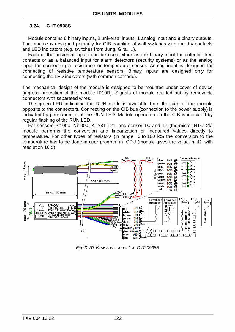
CIB UNITS, MODULES
TXV 004 13.02 122
3.24. C-IT-0908S
Module contains 6 binary inputs, 2 universal inputs, 1 analog input and 8 binary outputs. The module is designed primarily for CIB coupling of wall switches with the dry contacts and LED indicators (e.g. switches from Jung, Gira, ...).
Each of the universal inputs can be used either as the binary input for potential free contacts or as a balanced input for alarm detectors (security systems) or as the analog input for connecting a resistance or temperature sensor. Analog input is designed for connecting of resistive temperature sensors. Binary inputs are designed only for connecting the LED indicators (with common cathode).
The mechanical design of the module is designed to be mounted under cover of device (ingress protection of the module IP10B). Signals of module are led out by removable connectors with separated wires.
The green LED indicating the RUN mode is available from the side of the module opposite to the connectors. Connecting on the CIB bus (connection to the power supply) is indicated by permanent lit of the RUN LED. Module operation on the CIB is indicated by regular flashing of the RUN LED.
For sensors Pt1000, Ni1000, KTY81-121, and sensor TC and TZ (thermistor NTC12k) module performs the conversion and linearization of measured values directly to temperature. For other types of resistors (in range 0 to 160 kΩ) the conversion to the temperature has to be done in user program in CPU (module gives the value in kΩ, with resolution 10 Ω).
Fig. 3. 53 View and connection C-IT-0908S

3.24. C-IT-0908S
123 TXV 004 13.02 .
Tab. 3.24 Basic parameters C-IT-0908S Binary inputs
Quantity 6
Optional types of inputs
Normally open contact NO (0..>1,5kΩ / 1..<0,5kΩ), or balanced input (1x2k2, 2x1k1)
Galvanic isolation No
Binary outputs
Quantity, type 8, to drive LED indicators
Max, output current 3 mA
Open collector PNP max. voltage
27V
Galvanic isolation No
Power supply
Power supply and communication
24 V (27 V) from the CIB
Nominal power consumption
30 mA
Max. power consumption
65 mA
Operating and installation conditions
Operating temperature 0 ÷ +70 °C
Storage temperature -25 ÷ +85 °C
IP degree of protection acc. IEC 529
IP10B
Overvoltage category II (according to EN 60664)
Degree of pollution 1 (according to EN 60664)
Operating position Arbitrary
Type of operation Continuous
Fig. 3. 54 Simply balanced input for security detectors Fig. 3. 55 Double-balanced input for security detectors
Universal inputs, Analog inputs
Quantity of universal inputs
2
Optional types of universal inputs
Binary, balanced, Pt1000, Ni1000, NTC12kΩ, KTY81-121, resistance 160kΩ
Quantity of analog inputs.
1
Optional types of analog inputs
Binary, Pt1000, Ni1000, NTC12kΩ, KTY81-121, resistance 160kΩ
Resolution 0.1 °C / 10Ω
Accuracy 0,5 %
Period of refresh AI typically 5s
Galvanic isolation No
Universal inputs, Analog inputs
Binary input Normally open contact NO (0..>1,5kΩ / 1..<0,5kΩ),
Balanced input for security detectors
Resistance 1x2k2, or 2x1k1
Pt1000 –90 ÷ +320 °C
Ni1000 –60 ÷ +200 °C
NTC 12kΩ –40 ÷ +125 °C
KTY81-121 –55 ÷ +125 °C
Resistance input 0 ÷ 160kΩ
Dimensions and weight
Dimensions max. 55 × 26 × 16mm
Weight 7 g
Installation
Type under cover of device
Connecting Ribbon cable 0.15mm2 (CIB)
removable connectors with separated wires 0.14 mm
2 /10cm

CIB UNITS, MODULES
TXV 004 13.02 124
3.24.1. Configuration
Fig. 3.56 Module configuration
The input terminals DI/AI7 and DI/AI8 are shared for both binary and analog inputs (for digital and analog equipment). As the input is configured as analog one, it is not possible use it as binary input in the same time. In terms of configuration, the analog inputs are divided into two groups, 2 +1. In the first group there are the inputs AI7-AI8, the second group there is stand alone input AI9. Depending on the configured type of input (as enabled device) the specific items are accessible / inaccessible in configuration dialog. Enabling devices see. chap.2.1 Master configuration, check the box Show units, devices.
Balanced input By checking the item, the respective input will be evaluated as a simple balanced binary
alarm input. If the item is not checked, the respective input evaluated as a normal binary input (on/off).
Double balanced input By checking the item, respective input will be evaluated as a double balanced binary
alarm input. If the item is not checked and the input is configured for security systems (balanced input), the respective input evaluated as alarm input with a simple balance.
Delay, evaluation of long press For binary (momentary button) inputs module directly evaluate the short and long
presses on each input. By entering values one can set a delay time after which the activation of digital input DI is signalled as the long press (PRESS).Activating the digital input for period shorter than the

3.24. C-IT-0908S
125 TXV 004 13.02 .
entered value will be signalled as the short press (CLICK).Delay period (Tpress) can be inserted in the range 0.1÷2.5s.
Fig. 3. 57 Evaluation of short / long press
Type of input Choosing the type of analog input:
Pt1000, W100 = 1,385, -90/+320°C Pt1000, W100 = 1,391, -90/+320°C Ni1000, W100 = 1,617, -60/+200°C Ni1000, W100 = 1,500, -60/+200°C
NTC 12k (negative thermistor, 12k at 25°C), -40/+125°C KTY 81-121, -55/+125°C OV160k (0 ÷ 160kΩ)
Input filtering By specifying a non-zero value of the time constant, the 1st order digital filter is
activated. The filter is given by
1
1
xyy t
t
x - the current value of the analog input yt - output yt-1 - recent output time constant of the 1st order filter (TAU) - ح
Value of time constant is set in the range 0.1 ÷ 25.4 and it represents a time constant in the range of 100 ms ÷ 25.4 s (value 255 is intended for service purposes).
3.24.1. The structure of the transmitted data Module contains 5 devices in total:
- device 1, input, 8*DI/EZS
- device 2, output, 8*DO
- device 3, input, 1*STAT (status AIx)
- device 4, input, 2*AI (input AI7, AI8)
- device 5, input, 1*AI (input AI9)
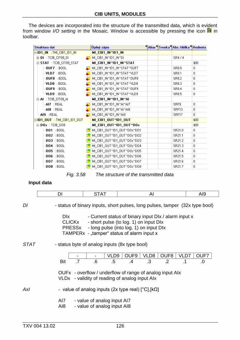
CIB UNITS, MODULES
TXV 004 13.02 126
The devices are incorporated into the structure of the transmitted data, which is evident from window I/O setting in the Mosaic. Window is accessible by pressing the icon in toolbar.
Fig. 3.58 The structure of the transmitted data
Input data
DI STAT AI AI9
DI - status of binary inputs, short pulses, long pulses, tamper (32x type bool) DIx - Current status of binary input DIx / alarm input x CLICKx - short pulse (to log. 1) on input DIx PRESSx - long pulse (into log. 1) on input DIx TAMPERx - „tamper“ status of alarm input x STAT - status byte of analog inputs (8x type bool)
- - VLD9 OUF9 VLD8 OUF8 VLD7 OUF7
Bit .7 .6 .5 .4 .3 .2 .1 .0 OUFx - overflow / underflow of range of analog input AIx VLDx - validity of reading of analog input AIx AxI - value of analog inputs (2x type real) [°C],[kΩ] AI7 - value of analog input AI7 AI8 - value of analog input AI8

3.24. C-IT-0908S
127 TXV 004 13.02 .
AI9 - value of analog input AI9 (1x type real) [°C],[kΩ]
The value of temperature sensor is transferred in °C (with resolution of 0.1°C), the value of general resistance in range 160kΩ is transferred in kΩ (with resolution of 10Ω).
Output data
DOs
DOs - status of binary LED outputs (8x type bool)
DO8 DO7 DO6 DO5 DO4 DO3 DO2 DO1
Bit .7 .6 .5 .4 .3 .2 .1 .0 DOx - value of binary LED output DOx
3.24.2. Module specifics
For the proper operation of this module in the CIB network the firmware version in the parent module CIB master MI2-01M / MI2-02M is required to be at least v1.6 or higher!!!

CIB UNITS, MODULES
TXV 004 13.02 128
3.25. C-OR-0008M
Module contains 8 relay outputs. Each output has the changeover contacts. Each output can be locally manually controlled by buttons on the module. Mechanical design corresponds to the modular design with width of 6M for mounting on the DIN-rail.
Due to the higher power consumption module has two power options. Either it is powered directly from the CIB line, or is supplied from an external source. In case of power supply module directly from the CIB line is necessary to keep the total maximum load CIB If the connection load is exceeded, the modules must be C-OR-0008 supplied from external sources (there is a strain CIB lines(see chapter 2.3 Power CIB bus). If the load of the CIB line is exceeded , the modules C-OR-0008 must be supplied from external sources (to relieve CIB load).
After connecting the module to the CIB line (power connected) the green RUN LED lights still. If the module is served by the CIB (it communicates), green RUN LED flashes regularly.
L
L
N
N
230 V AC
230 V AC
24 V DC
Fig. 3. 59 View and connection C-OR-0008M
Tab. 3.25 Basic parameters C-OR-0008M Binary relay outputs
Quantity 8
Outputs in group 1
Type of contacts Changeover (NO / NC)
Switched voltage Max. 300V AC / DC Min. 5V
Switched current Min. 100 mA Max. 16 A pro NO Max. 10 A pro NC
Closing time 15 ms
Opening time 5 ms
Binary relay outputs
Galvanic isolation Yes
Insulation voltage - between outputs
and internal circuits - between contacts
4000 V AC 1000 V AC
Mechanical lifetime Min. 20 000 000 cycles
Electrical lifetime Min. 50 000 cycles

3.25. C-OR-0008M
129 TXV 004 13.02 .
Protection against short circuit
No
Protection against inductive load
External (RC circuit, diode, varistor)
Power supply
Power supply and communication
24 V (27 V) from the CIB
External power 24 V DC
Max. power consumption
160 mA
Dimensions and weight
Dimensions 90 × 58 × 105mm
Weight 310g
3.25.1. Configuration
Fig. 3.60 Module configuration
Blocking of DO It can be set for binary outputs and for analog output AO1 if they should stay in their last
state or they should be disconnected during transition into HALT mode. Blocking of manual mode Checking the box the ability to manually control specific relay outputs in RUN mode is
blocked. In the HALT mode the manual control of relay outputs is always allowed. In RUN mode, the manual control is activated by pressing the button MANUAL
CONTROL on module. At the same time the yellow indicator LED lights up ON. Then it is possible to change the status of each output by respective buttons. Another pressing the button MANUAL CONTROL LED indicator ON goes off and the manual mode is cancelled. Then LED outputs are controlled according to the commands of the CIB line. Activity of manual mode is also indicated in the module status variable STAT.ManMode.
Operating and installation conditions
Operating temperature -10 ÷ +55 °C
Storage temperature -25 ÷ +70 °C
IP degree of protection acc. IEC 529
IP10B
Operating position Vertical
Type of operation Continuous
Installation on DIN rail
Connection terminals Screw-type
Cross-section of wires Max. 4 mm2

CIB UNITS, MODULES
TXV 004 13.02 130
3.25.1. The structure of the transmitted data
Module contains 2 devices in total:
- device 1, input, 1*STAT (status )
- device 2, output, 8*DO
The devices are incorporated into the structure of the transmitted data, which is evident from window I/O setting in the Mosaic. Window is accessible by pressing the icon in toolbar.
Fig. 3.61 The structure of the transmitted data
Input data
STAT
STAT - status byte of module (8x type bool)
PowerErr ManMode - - - - - -
Bit .7 .6 .5 .4 .3 .2 .1 .0
ManMode - signalling of manual control mode of binary outputs. PowerErr - supply voltage drop below the limit for guaranteed switching
of relay outputs DO
Output data
DOs
DOs - value of binary outputs (8x type bool)
DO8 DO7 DO6 DO5 DO4 DO3 DO2 DO1
Bit .7 .6 .5 .4 .3 .2 .1 .0
DOx - value of binary output DOx

3.26. C-OR-0202B
131 TXV 004 13.02 .
3.26. C-OR-0202B
The module contains 2 relay outputs with changeover contact and 2 analog/digital inputs. Inputs allow connection of temperature sensor or potential-free switching contacts. The module is mechanically designed in the "box" for mounting into a flush installation box.
After connecting the module to the CIB line (power connected) the green RUN LED lights still. If the module is served by the CIB (it communicates), green RUN LED flashes regularly.LED indicators DOx indicate the status of binary outputs.
Tab. 3.26 Basic parameters C-OR-0202B
Fig. 3. 62 view C-OR-0202B
Power supply
Power supply and communication
24 V (27 V) from the CIB
Max. power consumption
50mA
Galvanic isolation No
Dimensions and weight
Dimensions 50 × 50 × 30mm
Weight 70 g
Operating and installation conditions
Operating temperature -10 ÷ +55 °C
Storage temperature -25 ÷ +70 °C
IP degree of protection acc. IEC 529
IP20B
Operating position Arbitrary
Type of operation Continuous
Fig. 3. 63 Simply balanced input for security detectors Fig. 3. 64 Double-balanced input for security detectors
Universal inputs AI/DI
Quantity 2
Optional types of inputs Binary, balanced, Pt1000, Ni1000, NTC12kΩ, KTY81-121, resistance 160kΩ
Binary input NO - normally open dry contact
Balanced input for security detectors
Resistance 1x2k2, or 2x1k1
Pt1000 –90 ÷ +320 °C
Ni1000 –60 ÷ +200 °C
NTC 12kΩ –40 ÷ +125 °C
KTY81-121 –55 ÷ +125 °C
Resistance input 0 ÷ 160kΩ
Resolution 0.1 °C / 10Ω
Accuracy1)
0,5 %
Period of refresh AI typically 5s
Galvanic isolation of CIB No
Binary outputs DO
Quantity 2
Number of outputs in group
1
Type of operation relay, changeover contacts
Switched voltage max. 300V AC/DC min. 5V
Switched current max. 16A for NO max. 10A for NO min. 100mA
Installation
Type into the flush box
Connecting CIB and AI/DI
Screw type terminal
Cross-section of wires max. 1.5 mm2
Connecting the power cables
6x cable CY
Cross-section of wires 2.5 mm2, length 90mm
1) The measurement error rises for resistors higher
than 50kΩ.

CIB UNITS, MODULES
TXV 004 13.02 132
3.26.1. Configuration
Fig. 3.65 Module configuration
The input terminals DI/AIx are shared for binary and analog inputs (for digital and analog equipment).As the input is configured as analog one, it is not possible use it as binary input in the same time. Depending on the configured input (as enabled devices) specific items of configuration dialog are enabled/disabled. Enabling devices see. chap.2.1 Master configuration, check the box Show units, devices
Balanced input By checking the item, the respective input will be evaluated as a simple balanced binary
alarm input. If the item is not checked, the respective input evaluated as a normal binary input (on/off).
Double balanced input By checking the item, respective input will be evaluated as a double balanced binary
alarm input. If the item is not checked and the input is configured for security systems (balanced input), the respective input evaluated as alarm input with a simple balance.
Type of input Choosing the type of analog input:
Pt1000, W100 = 1,385, -90/+320°C Pt1000, W100 = 1,391, -90/+320°C Ni1000, W100 = 1,617, -60/+200°C Ni1000, W100 = 1,500, -60/+200°C
NTC 12k (negative thermistor, 12k at 25°C), -40/+125°C KTY 81-121, -55/+125°C OV160k (0 ÷ 160kΩ)

3.26. C-OR-0202B
133 TXV 004 13.02 .
Input filtering
By specifying a non-zero value of the time constant, the 1st order digital filter is activated. The filter is given by
1
1
xyy t
t
x - the current value of the analog input yt - output yt-1 - recent output time constant of the 1st order filter (TAU) - ح
Value of time constant is set in the range 0.1 ÷ 25.4 and it represents a time constant in the range of 100 ms ÷ 25.4 s (value 255 is intended for service purposes).
Blocking of DO It can be set for binary outputs and for analog output AO1 if they should stay in their last
state or they should be disconnected during transition into HALT mode. 3.26.2. The structure of the transmitted data
Module contains 5 devices in total:
- device 1, input, . 1*STAT (status AI)
- device 2, input, 1*AI (analog input 1)
- device 3, input, 1*AI (analog input 2)
- device 4, input, 2*DI
- device 5, output, 2*DO
The devices are incorporated into the structure of the transmitted data, which is evident from window I/O setting in the Mosaic. Window is accessible by pressing the icon in toolbar.

CIB UNITS, MODULES
TXV 004 13.02 134
Fig. 3.66 The structure of the transmitted data
Input data
STAT AI1 AI2 DI
STAT - status byte of analog inputs (8x type bool)
- - - - VLD2 OUF2 VLD1 OUF1
Bit .7 .6 .5 .4 .3 .2 .1 .0
OUF1 - overflow / underflow of range of analog input AI1 VLD1 - AI1 analog input reading validity OUF2 - overflow / underflow of range of analog input AI2 VLD2 - AI2 analog input reading validity AI1 - value of analog input AI1 (type real) [°C],[kΩ]
AI2 - value of analog input AI2 (type real) [°C],[kΩ] The value of temperature sensor is transferred in °C (with resolution of
0.1°C), the value of general resistance in range 160kΩ is transferred in kΩ (with resolution of 10Ω).
DI - status of binary inputs, signalling "tamper" status of alarm inputs (8x type
bool)
- - TAMPER2 TAMPER1 - - DI2 DI1
Bit .7 .6 .5 .4 .3 .2 .1 .0
DI1 - the current status of the binary DI1/balanced for alarm input1
DI2 - the current status of the binary DI2/balanced for alarm input 2
TAMPER1 - tamper status on balanced input 1 TAMPER2 - tamper status on balanced input 2 Output data
DOs
DOs - value of binary outputs (8x type bool)
- - - - - - DO2 DO1
Bit .7 .6 .5 .4 .3 .2 .1 .0
DO1 - value of binary output DO1 DO2 - value of binary output DO2

3.27. C-RC-0002R
135 TXV 004 13.02 .
3.27. C-RC-0002R
Module in interior design for office and residential interiors is designed to display the current temperature and set the new request temperature. The module thus serves as a simpler variant of the Room Control Manager. Includes 3-digit LCD display, 3 buttons and 1 LED indicator. Internal temperature sensor is integrated in the module. The module also has a universal DI/AI input that can be configured to connect external temperature sensor (e.g. temperature of the floor heating).
Module is designed to be installed on the wall into flush box. The module consists of two parts. The first part contains the interior unit, the second part is used to connect the module to the CIB bus. Both parts are connected to each other by ribbon cable with connector. Signalling green RUN LED is accessible from the side of module opposite to ribbon cable. Connecting on the CIB bus (connection to the power supply) is indicated by permanent lit of the RUN LED. Module operation on the CIB is indicated by regular flashing of the RUN LED.
Module is designed for Time and Element designs of ABB production. For actual offer of designs see the catalogue of Teco
Fig. 3. 67 View and connection C-RC-0002R
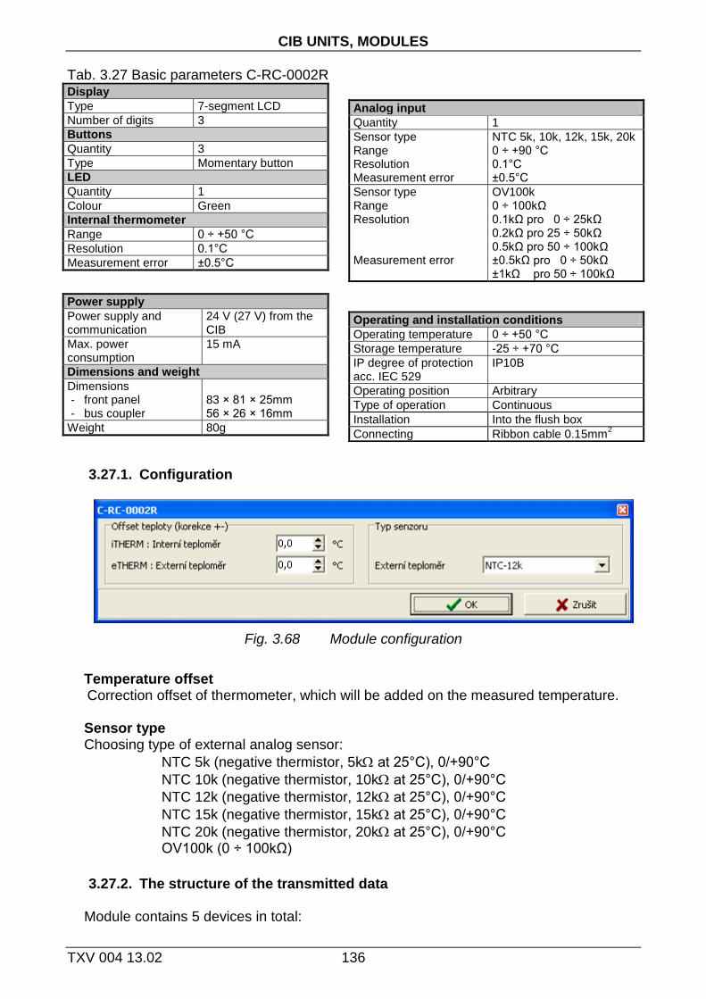
CIB UNITS, MODULES
TXV 004 13.02 136
Tab. 3.27 Basic parameters C-RC-0002R Display
Type 7-segment LCD
Number of digits 3
Buttons
Quantity 3
Type Momentary button
LED
Quantity 1
Colour Green
Internal thermometer
Range 0 ÷ +50 °C
Resolution 0.1°C
Measurement error ±0.5°C
Power supply
Power supply and communication
24 V (27 V) from the CIB
Max. power consumption
15 mA
Dimensions and weight
Dimensions - front panel - bus coupler
83 × 81 × 25mm 56 × 26 × 16mm
Weight 80g
3.27.1. Configuration
Fig. 3.68 Module configuration
Temperature offset
Correction offset of thermometer, which will be added on the measured temperature. Sensor type Choosing type of external analog sensor:
NTC 5k (negative thermistor, 5k at 25°C), 0/+90°C
NTC 10k (negative thermistor, 10k at 25°C), 0/+90°C
NTC 12k (negative thermistor, 12k at 25°C), 0/+90°C
NTC 15k (negative thermistor, 15k at 25°C), 0/+90°C
NTC 20k (negative thermistor, 20k at 25°C), 0/+90°C OV100k (0 ÷ 100kΩ)
3.27.2. The structure of the transmitted data
Module contains 5 devices in total:
Analog input
Quantity 1
Sensor type Range Resolution Measurement error
NTC 5k, 10k, 12k, 15k, 20k 0 ÷ +90 °C 0.1°C ±0.5°C
Sensor type Range Resolution Measurement error
OV100k 0 ÷ 100kΩ 0.1kΩ pro 0 ÷ 25kΩ 0.2kΩ pro 25 ÷ 50kΩ 0.5kΩ pro 50 ÷ 100kΩ ±0.5kΩ pro 0 ÷ 50kΩ ±1kΩ pro 50 ÷ 100kΩ
Operating and installation conditions
Operating temperature 0 ÷ +50 °C
Storage temperature -25 ÷ +70 °C
IP degree of protection acc. IEC 529
IP10B
Operating position Arbitrary
Type of operation Continuous
Installation Into the flush box
Connecting Ribbon cable 0.15mm2

3.27. C-RC-0002R
137 TXV 004 13.02 .
- device 1, input, 1*STAT (status AI)
- device 2, input, 1*AI (internal thermometer)
- device 3, input, 1*AI (external thermometer)
- device 4, input, 3*DI (buttons)
- device 5, input, 1*DISP (display)
The devices are incorporated into the structure of the transmitted data, which is evident from window I/O setting in the Mosaic. Window is accessible by pressing the icon in toolbar.
Fig. 3.69 The structure of the transmitted data
Input data
STAT iTHERM eTHERM BTN
STAT - status byte of analog inputs (8x type bool)
- - - - VLD2 OUF2 VLD1 OUF1
Bit .7 .6 .5 .4 .3 .2 .1 .0
OUF1 - overflow / underflow of internal thermometer range VLD1 - internal thermometer reading validity OUF2 - overflow / underflow of range of external thermometer VLD2 - external thermometer reading validity iTHERM - value of internal thermometer (type real) [°C]

CIB UNITS, MODULES
TXV 004 13.02 138
eTHERM - value of external thermometer (type real) [°C] The value of temperature sensor is transferred in °C (with resolution of
0.1°C), the value of general resistance in range 100kΩ is transferred in kΩ (with resolution of 0.1/0.2/0.5kΩ).
BTN - status of buttons (8x type bool)
- - - - - UP DOWN MODE
Bit .7 .6 .5 .4 .3 .2 .1 .0
MODE - status of button MODE DOWN - status of button DOWN UP - status of button UP
Output data
DISP
DISP - variables of the LCD display (3x type usint + 6x type bool)
DISP.TEXT - ASCII characters to be displayed (see next chapter) DISP.LED_ON - LED control DISP.LED_Blink - flashing of LED (in 150ms raster, at LED_ON=1) DISP.Disp_OFF - turn off the characters displayed on the screen DISP.Disp_Blink - flashing of displayed characters (in 150ms raster, at DISP_OFF=0) DISP.Dot1 - display 1st decimal point on the display DISP.Dot2 - display 2nd decimal point on the display
3.27.1. Module specifics
Integrated seven-segment LCD display module allows you to display only a limited set of ASCII characters. Displayable ASCII characters are listed in the following list:' ', ", Ξ, -, 0, 1, 2, 3, 4, 5, 6, 7, 8, 9, =, A, C, E, F, G, H, I, J, L, P, S, U, ], °, _, b, c, d, h, i, n, o, r, t, u.
Module mounting Complete module C-RC-0002R comes disassembled into 4 parts (housing with
temperature sensor, intermediate frame, outer frame, set of the panel with display and bus coupler) because the easy installation at the end user site. The assembly process is described in detail in the documentation for the module (TXV 133 33), which is supplied with the module.

3.28. C-RC-0003R
139 TXV 004 13.02 .
3.28. C-RC-0003R
LCD display module in interior design is intended to show the two values (e.g., temperature, humidity, ....) and four symbols (icons). The module also has a universal DI / AI input that can be configured to connect the contact of the switch button, or for connecting a resistive sensors (e.g. temperature of the floor heating).As a variant, the module can equipped with internal thermometer, hygrometer and three buttons.
Module is designed to be installed on the wall into flush box. The module consists of two parts. The first part contains the front panel unit (available in several design versions), the second part is used to connect the module to the CIB bus. Both parts are connected to each other by ribbon cable with connector. The green LED indicating the RUN mode is available from the side of the module next to the connector. Connecting on the CIB bus (connection to the power supply) is indicated by permanent lit of the RUN LED. Module operation on the CIB is indicated by regular flashing of the RUN LED.
Module is designed for various designs of wall switches from various manufacturers including EFAPEL, Bticino, LUTRON etc. For actual offer see the catalogue.
Fig. 3. 70 Preview and connection C-RC-0003R
Tab. 3.28 Basic parameters C-RC-0003R Display
Type LCD backlight
Size 27x21mm (98x64pixel)
Number of displayed values
2 + unit symbols
Number of symbols/icons
4
Backlight continuously adjustable
Buttons (optional)
quantity 3
Type Momentary button
Internal thermometer (optional) Range -40 ÷ +125°C
Resolution / accuracy 0.1 °C / typ. 0.3 °C
The period of reading typically 5s
Internal hygrometer (optional)
Range 0 ÷ 100% RH
Resolution / accuracy 1% / typ. 2%
Universal input DI/AI
quantity 1
Optional input type Binary, Pt1000, Ni1000, NTC12kΩ, KTY81-121, resistance 160kΩ
Binary input NO contact (0/1) (Normally Open)
Pt1000 –90 ÷ +320 °C
Ni1000 –60 ÷ +200 °C
NTC 12kΩ –40 ÷ +125 °C
KTY81-121 –55 ÷ +125 °C
Resistor input 0 ÷ 160kΩ
Resolution 0.1 °C / 10Ω
Accuracy 0,5 % of range
The period of reading AI typically 5s

CIB UNITS, MODULES
TXV 004 13.02 140
The period of reading typically 5s
Power supply
Power supply and communication
24 V (27 V) from the CIB
Typical power consumption
10mA (without backlight)
Max. power consumption
17mA
Dimensions and weight
Dimensions - front panel - bus coupler
86 × 86 × 18mm 42 × 27 × 17mm
Weight 80g
3.28.1. Configuration
Fig. 3.71 Module configuration
Delay, evaluation of long press For binary (momentary button) inputs module directly evaluate the short and long
presses on each input. By entering values one can set a delay time after which the activation of digital input DI is signalled as the long press (PRESS).Activating the digital input for period shorter than the entered value will be signalled by as the short press (CLICK).Delay period (Tpress) can be inserted in the range 0.1÷2.5s.
Fig. 3. 72 Evaluation of short/long press
Operating and installation conditions
Operating temperature 0 ÷ +50 °C
Storage temperature -25 ÷ +70 °C
IP degree of protection acc. IEC 529
IP10B
Operating position arbitrary
Type of operation continuous
Installation Into the flush box
Connecting the front panel
Ribbon cable 0.15mm2
Connecting the bus coupler
Spring-loaded terminals, 0.15 ÷ 0.5 mm
2

3.28. C-RC-0003R
141 TXV 004 13.02 .
Type of input Choosing the type of analog input:
Pt1000, W100 = 1,385, -90/+320°C Pt1000, W100 = 1,391, -90/+320°C Ni1000, W100 = 1,617, -60/+200°C Ni1000, W100 = 1,500, -60/+200°C
NTC 12k (negative thermistor, 12k at 25°C), -40/+125°C KTY 81-121, -55/+125°C OV160k (0 ÷ 160kΩ)
Input filtering By specifying a non-zero value of the time constant, the 1st order digital filter is
activated. The filter is given by
1
1
xyy t
t
x - the current value of the analog input yt - output yt-1 - recent output time constant of the 1st order filter (TAU) - ح
Value of time constant is set in the range 0.1 ÷ 25.4 and it represents a time constant in the range of 100 ms ÷ 25.4 s (value 255 is intended for service purposes).
Temperature offset Correction offset of thermometer, which will be added on the measured temperature. Display contrast
Setting the display contrast, in the range 0 to 127 (0 - low contrast, 127 - high contrast). Display layout Graphical layout of the content of the display can be changed by the user. There is a
choice of two options, Type1 or Type2. Layout of the display is depicted below. .

CIB UNITS, MODULES
TXV 004 13.02 142
S1÷S4 - view symbols / modes VAL1 - primary value including the unit VAL2 - secondary value including the unit B - button labels
Button labels Checking the box, the labels of each button will be displayed in B area.
3.28.2. The structure of the transmitted data
Module contains 6 devices in total:
- device 1, input, 3*BUTT + 1*DI (button + DI1)
- device 2, input, 1*DISP (display)
- device 3, input, 1*STAT (status AI)
- device 4, input, 1*AI (internal thermometer)
- device 5, input, 1*AI (internal hygrometer)
- device 6, input, 1*AI (AI1)
The devices are incorporated into the structure of the transmitted data, which is evident from the panel I/O settings in Mosaic. Panel is available by clicking on the icon in the toolbar.
Fig. 3.73 The structure of the transmitted data
Input data
DI STAT THERM RH AI1
DI - button/binary inputs status (16x type bool)
DI1 BUT3 BUT2 BUT1
Bit .3 .2 .1 .0
CLICK_DI1 CLICK_BUT3 CLICK_BUT2 CLICK_BUT1
Bit .7 .6 .5 .4

3.28. C-RC-0003R
143 TXV 004 13.02 .
PRES_DI1 PRESS_BUT3 PRESS_BUT2 PRESS_BUT1
Bit .11 .10 .9 .8
- - - -
Bit .15 .14 .13 .12 BUTx - the current status of the BUTx button DI1 - the current status of the binary DI1 input CLICK_BUTx - short press of the BUTx button CLICK_DI1 - short press on the DI1 input PRESS_BUTx - long press of the BUTx button PRESS_DI1 - long press on the DI1 input STAT - status byte of analog inputs (8x type bool)
- - VLD1 OUF1 VLDR OUFR VLDT OUFT
Bit .7 .6 .5 .4 .3 .2 .1 .0 OUFT - overflow / underflow of thermometer range VLDT - thermometer reading validity OUFR - overflow / underflow of hygrometer range VLDR - hygrometer reading validity OUF1 - overflow / underflow of analog input AI1 VLD1 - AI1 analog input reading validity THERM - temperature (1x type real) [°C] RH - relative humidity (1x type real) [%] AI1 - value of analog input AI1 (1x type real) [°C],[kΩ]
The value of temperature sensor is transferred in °C (with resolution of
0.1°C), the value of general resistance in range 160kΩ is transferred in kΩ (with resolution of 10Ω).
Input data
DISP
DISP - output data zone of the display DISP.CONT - control word of display (8x type bool)
blinkS4 blinkS3 blinkS2 blinkS1 blink22 blink21 blink12 blink11
Bit .7 .6 .5 .4 .3 .2 .1 .0 blinkSx - blinking of respective symbols Sx 0 - does not flash 1 - flash blink1x - blinking of individual digits of the value VAL1 blink2x - blinking of individual digits of the value VAL2

CIB UNITS, MODULES
TXV 004 13.02 144
0x00 - does not flash 0x01 - flashing lower 2 digits (Low) 0x10 - flashing higher 2 digits (High) 0x11 - flashing all digits Flashing is in 500ms period. DISP.VAL1 - primary value is displayed in the range -9999 ÷ +9999 (1x type int) DISP.VAL2 - secondary value is displayed in the range -9999 ÷ +9999 (1x type int) DISP.SYMBOLS - display symbols(1x type word)
S2 S1
Bit .7 .6 .5 .4 .3 .2 .1 .0
S4 S3
Bit .15 .14 .13 .12 .11 .10 .9 .8 S1 - display symbol / mode S1 S2 - display symbol / mode S2 S3 - display symbol / mode S3 S4 - display symbol / mode S4
The specific form of the symbol of displayed/selected mode is given by display format, see chapter Configuration.
Type1 Type2
S1÷S4 S1,S3 S2,S4
0x00
0x01 OFF
0x02 Heat
0x03 Cool
0x04 Auto
0x05 Fan
0x06 Dry
0x07 On
0x08 Cycle
0x09 High
0x0A Medium
0x0B Low
0x0C Top
0x0D
0x0E
0x0F

3.28. C-RC-0003R
145 TXV 004 13.02 .
DISP.UNITS1 - units and display format of primary value (1x type usint) DISP.UNITS2 - units and display format of secondary value (1x type usint)
FORM UNIT
Bit .7 .6 .5 .4 .3 .2 .1 .0 FORM - display format 0x00 - with a decimal point (xxx.x) 0x01 - without a decimal point (xxxx) 0x10 - with a colon, time format (xx:xx) 0x11 - UNIT - unit displayed 0x00 - 0x01 - °C 0x02 - °F 0x03 - % 0x04 - rH 0x05 - kW 0x06 - ppm 0x07 - time symbol, "hourglass" DISP.LIGHT - display backlight (1x type usint)
BLINK VAL
Bit .7 .6 .5 .4 .3 .2 .1 .0 BLINK - flashing backlight (in 500ms period) 0 - does not flash 1 - flash VAL - level of display backlight, 0÷100[%]

CIB UNITS, MODULES
TXV 004 13.02 146
3.29. C-RI-0401S
The module contains 1 output of IR (infrared) transmitter, 1 input of IR receiver demodulator, 1 input for light intensity sensor (BPW21), one output LED indicator and 2 universal inputs. Each of the universal inputs can be used by either the potential-free binary input or the analog input for connecting a resistance temperature sensor.
The mechanical design of the module is designed to be mounted under cover of device (ingress protection of the module IP10B). Signals of the module are available on ribbon cable. signalling green RUN LED is accessible from the side of module opposite to ribbon cable. Connecting on the CIB bus (connection to the power supply) is indicated by permanent lit of the RUN LED. Module operation on the CIB is indicated by regular flashing of the RUN LED.
For sensors Pt1000, Ni1000, KTY81-121, and sensor TC and TZ (thermistor NTC12k) module performs the conversion and linearization of measured values directly to temperature. For other types of resistors (in range 0 to 160 kΩ) the conversion to the temperature has to be done in user program in CPU (module gives the value in kΩ, with resolution 10 Ω).
Fig. 3. 74 View and connection C-RI-0401S

3.29. C-RI-0401S
147 TXV 004 13.02 .
Tab. 3.29 Basic parameters C-RI-0401S Universal DI/AI inputs
Quantity 2
Optional types of inputs
Binary, Pt1000, Ni1000, NTC12kΩ, KTY81-121, resistance 160kΩ
Binary input NO contact (0/1) (Normally Open)
Pt1000 –90 ÷ +320 °C
Ni1000 –60 ÷ +200 °C
NTC 12kΩ –40 ÷ +125 °C
KTY81-121 –55 ÷ +125 °C
Resistance input 0 ÷ 160kΩ
Resolution 0.1 °C / 10Ω
Accuracy 2 %
Power supply
Power supply and communication
24 V (27 V) from the CIB
Max. power consumption
25 mA
Dimensions and weight
Dimensions 55 × 32 × 13mm
Weight 8g
3.29.1. Configuration
Fig. 3.75 Module configuration
The input terminals DI/AIx are shared for binary and analog inputs (for digital and
analog equipment).As the input is configured as analog one, it is not possible use it as binary input in the same time. Depending on the configured input (as enabled devices) specific items of configuration dialog are enabled/disabled. Enabling devices see. chap.2.1 Master configuration, check the box Show units, devices
Type of input Choosing the type of analog input:
Pt1000, W100 = 1,385, -90/+320°C Pt1000, W100 = 1,391, -90/+320°C Ni1000, W100 = 1,617, -60/+200°C
Input of light intensity sensor
Quantity, type of sensor 1, photodiode BPW21
Range of measurement 0 ÷ 50000 lx
Accuracy of measurement
5 %
Input of IR receiver demodulator
Quantity 1
Power supply for demodulator
3.3 V
Demodulator pilot frequency
36 kHz
Output of IR transmitter
Quantity 1
Power supply of transmitter
3.3 V
Type of IR transmitter IR LED (IFMAX = 100mA) + resistor according to IF
(e.g. for IR LED UF =1.2V, IF = 20mA -> R = 100Ω)
Operating and installation conditions
Operating temperature -10 ÷ +55 °C
Storage temperature -25 ÷ +70 °C
IP degree of protection acc. IEC 529
IP10B
Operating position Arbitrary
Type of operation Continuous
Installation under cover of device
Connecting Ribbon cable 0.15mm2 (CIB)
removable connectors with separated wires 0.14 mm
2
/10cm

CIB UNITS, MODULES
TXV 004 13.02 148
Ni1000, W100 = 1,500, -60/+200°C
NTC 12k (negative thermistor, 12k at 25°C), -40/+125°C KTY 81-121, -55/+125°C OV160k (0 ÷ 160kΩ)
Input filtering By specifying a non-zero value of the time constant, the 1st order digital filter is
activated. The filter is given by
1
1
xyy t
t
x - the current value of the analog input yt - output yt-1 - recent output time constant of the 1st order filter (TAU) - ح Value of time constant is set in the range 0.1 ÷ 25.4 and it represents a time constant in the range of 100 ms ÷ 25.4 s (value 255 is intended for service purposes).
3.29.2. The structure of the transmitted data
Module contains 6 devices in total:
- device 1, input, 1*STAT (status AIx, light intensity
sensor)
- device 2, input, 2*AI (thermometers)
- device 3, input, 1*AI (light intensity sensor)
- device 4, input, 2*DI
- device 5, input/output, 1*IRI/IRO (infrared receiver/transmitter)
The devices are incorporated into the structure of the transmitted data, which is evident from window I/O setting in the Mosaic. Window is accessible by pressing the icon in toolbar.
Fig. 3.76 The structure of the transmitted data
Input data
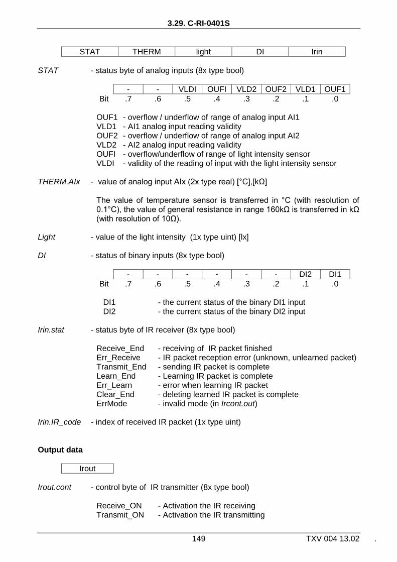
3.29. C-RI-0401S
149 TXV 004 13.02 .
STAT THERM light DI Irin
STAT - status byte of analog inputs (8x type bool)
- - VLDI OUFI VLD2 OUF2 VLD1 OUF1
Bit .7 .6 .5 .4 .3 .2 .1 .0
OUF1 - overflow / underflow of range of analog input AI1 VLD1 - AI1 analog input reading validity OUF2 - overflow / underflow of range of analog input AI2 VLD2 - AI2 analog input reading validity OUFI - overflow/underflow of range of light intensity sensor VLDI - validity of the reading of input with the light intensity sensor THERM.AIx - value of analog input AIx (2x type real) [°C],[kΩ]
The value of temperature sensor is transferred in °C (with resolution of
0.1°C), the value of general resistance in range 160kΩ is transferred in kΩ (with resolution of 10Ω).
Light - value of the light intensity (1x type uint) [lx]
DI - status of binary inputs (8x type bool)
- - - - - - DI2 DI1
Bit .7 .6 .5 .4 .3 .2 .1 .0
DI1 - the current status of the binary DI1 input DI2 - the current status of the binary DI2 input Irin.stat - status byte of IR receiver (8x type bool)
Receive_End - receiving of IR packet finished Err_Receive - IR packet reception error (unknown, unlearned packet) Transmit_End - sending IR packet is complete Learn_End - Learning IR packet is complete Err_Learn - error when learning IR packet Clear_End - deleting learned IR packet is complete ErrMode - invalid mode (in Ircont.out) Irin.IR_code - index of received IR packet (1x type uint)
Output data
Irout
Irout.cont - control byte of IR transmitter (8x type bool)
Receive_ON - Activation the IR receiving Transmit_ON - Activation the IR transmitting

CIB UNITS, MODULES
TXV 004 13.02 150
Learn_ON - Activation the IR learning mode Learn_Mask - reserve Clear - Activation of IR deleting mode LED_AUTO - automatic flashing LED when receiving IR packet = 1 - 1x long flash in the successful IR reception - 3x short flashes during a failed IR reception = 0 - manual control of LED (bits LED_ON and
LED_Blink) LED_ON - status of LED indicator, 0/1 = off / on LED_Blink - flashing of LED (in 150ms raster, at LED_ON=1)
Irout.IR_code - index of transmitted IR packet (1x type uint)
3.29.3. Description of function IR receiver / transmitter
IR receiver and IR transmitter in module are designed to capture and generate IR signal from the IR remote controllers, using the control of different types of appliances (e.g. air conditioners).The module can handle any IR signal (packet) sent from the IR remote controller that works with a carrier frequency of 36kHz. The captured IR packet from the remote control can be learned/saved and consequently reproduced (transmitted).This makes it possible to replace the original manual control via IR remote control by automated control over C-RI-0401S module. The module allows you to save about. 100 different IR packets/commands.
IR learning procedure
Learning procedure is initiated by setting the index of learned packet to Irout.IR_code
variable (packet index must not be 0 (0x0000) and/or 65535 (0xFFFF) - they are dedicated values!!!). Then the variable Irout.cont.Learn_On has to be set on 1 so the module turns to the receiving state and awaits the IR packet to be learned..
Successful reception and processing of learned packet is signalled by setting the variable Irin.stat.Learn_End = 1. In case of unsuccessful packet teaching cycle also the variable Irin.stat.Err_Learn = 1 is set and the learning procedure must be repeated.
Termination (reset) of the enrolment is done by setting the variable Irout.cont.Learn_On = 0, thus the flags Irin.stat.Learn_End and Irin.stat.Err_Learn are cleared in status byte. Learning another IR packet is re-activated by setting the variable Irout.cont.Learn_On = 1.
Learned IR packets are stored in the module and the ON / OFF power module. IR receiving In this mode, the module receives learned IR packets. Activation of IR reception is done
by setting the variable Irout.cont.Receive_On = 1. The module goes into receiving mode and waits for coming IR packet.
Successful acceptation of learned packet is signalled by setting the variable Irin.stat.Receive_End = 1 and setting the index of the received packet in the variableIrin.IR_code. If the module accepts unknown packet (which is not taught in the module) also the variable is set Irin.stat.Err_Receive = 1 and variable Irin.IR_code = 0.
Termination (reset) of the receiving mode can be done by setting the variable Irout.cont.Receive_On = 0, which clear the flags Irin.stat.Receive_End and Irin.stat.Err_Receive in the status byte and variable Irin.IR_code. Receiving another IR packet is activated by setting the variable Irout.cont.Receive_On = 1.

3.29. C-RI-0401S
151 TXV 004 13.02 .
IR transmitting
For transmitting of IR packet the index of the desired packet must be set first into the variable Irout.IR_code. Transmitting of the desired packet is started by setting the variable Irout.cont.TransmitOn = 1. End of transmitting the whole packet is indicated by setting variable Irin.stat.Transmit_End = 1.
Termination (reset) of the transmitting mode can be done by setting the variable Irout.cont.TransmitOn = 0, which clear the flag Irin.stat.Transmit_End. Transmitting of another IR packet is activated by setting the variable Irout.cont.TransmitOn = 1.
IR clearing
To delete a learned IR packet from the module the index of deleting packet has to be set to variable Irout.IR_code and then the variable Irout.cont.Clear = 1 is set. Clearing the IR packet is signaled by setting the variable Irin.stat.Clear_End = 1. If you want to erase all learned IR packets at the same time, it is possible to set the value 65535 (0xFFFF) into a variable Irout.IR_code .
Termination (reset) of deleting is done by setting the variable Irout.cont.Clear = 0, which clear the flag Irin.stat.Clear_End from the status byte. Next deleting can be done by re-setting the variable Irout.cont.Clear = 1.
It is not necessary to delete the original learned IR packet, the index is rewrited by the new learned IR packet.

CIB UNITS, MODULES
TXV 004 13.02 152
3.30. C-WG-0503S
The module is designed to connect readers of contactless RFID identifiers that communicate via Wiegand interface (e.g. Aktion AXR-100 from EFG CZ spol. Ltd., or Samsung SSA-R1001, SSA-R2000V or others). In addition to the signal from the card readers the module also contains one binary input for potential-free contacts, two universal inputs and 3 digital outputs (OC).
Each of the universal inputs can be used either as the binary input for potential free contacts or as a balanced input for alarm detectors (security systems) or as the analog input for connecting a resistance or temperature sensor. Inputs for the reader can be reconfigured to function of 2 binary inputs. The module can therefore operate either in a configuration Wiegand + 1*DI + 2*AI/DI + 3*DO or in configuration 3*DI + 2*AI/DI + 3*DO.
The mechanical design of the module is designed to be mounted under cover of device (ingress protection of the module IP10B). Signals of module are led out by removable connectors with separated wires.
The green LED indicating the RUN mode is available from the side of the module opposite to the connectors. Connecting on the CIB bus (connection to the power supply) is indicated by permanent lit of the RUN LED. Module operation on the CIB is indicated by regular flashing of the RUN LED.
For sensors Pt1000, Ni1000, KTY81-121, and sensor TC and TZ (thermistor NTC12k) module performs the conversion and linearization of measured values directly to temperature. For other types of resistors (in range 0 to 160 kΩ) the conversion to the temperature has to be done in user program in CPU (module gives the value in kΩ, with resolution 10 Ω).
Fig. 3. 77 View and connection C-WG-0503S

3.30. C-WG-0503S
153 TXV 004 13.02 .
Tab. 3.30 Basic parameters C-WG-0503S Wiegand inputs, Binary inputs (DI1,DI2,DI3)
Quantity 3
Type TTL 5V
Pull -up resistance 3.9kΩ
Galvanic isolation No
Wiegand interface 26/34/42 bit (3/4/5 B)
- Pulse width / delay typ. 60÷100us / 1÷2ms
Binary outputs (DO1,DO2,DO3)
Quantity 3
Type Open collector NPN
Switched voltage max. 30V
Switched current max. 30mA
Galvanic isolation No
Power supply
Power supply and communication
24 V (27 V) from the CIB
Nominal power consumption
20 mA
Max. power consumption
85 mA
Operating and installation conditions
Operating temperature 0 ÷ +70 °C
Storage temperature -25 ÷ +85 °C
IP degree of protection acc. IEC 529
IP10B
Overvoltage category II (according to EN 60664)
Degree of pollution 1 (according to EN 60664)
Operating position Arbitrary
Type of operation Continuous
Fig. 3. 78 Simply balanced input for security detectors Fig. 3. 79 Double-balanced input for security detectors
Universal inputs DI/AI/EZS (DI/AI4, DI/AI5)
Quantity 2
Optional types of universal inputs
Binary, balanced, 1x2k2, 2x1k1, Pt1000, Ni1000, NTC12kΩ, KTY81-121, resistance 160kΩ
Threshold level of DI 0…>1.5kΩ, 1…<0.5kΩ
Internal voltage DI 3.3V
Internal resistance of DI 2.2kΩ
Resolution AI 0.1 °C / 10Ω
Accuracy AI 0,5 %
Galvanic isolation No
Power output
Output voltage 12V DC
Output current max. 60mA
The period of data refresh
Analog inputs typically 5s
Other inputs typically 160ms
Dimensions and weight
Dimensions max. 55 × 26 × 16mm
Weight 7 g
Installation
Type under cover of device
Connecting Ribbon cable 0.15mm2 (CIB)
removable connectors with separated wires 0.14 mm
2
/10cm

CIB UNITS, MODULES
TXV 004 13.02 154
3.30.1. Configuration
Fig. 3.80 Module configuration
Some inputs, input terminals are shared for more functions of module. Wiegand data
inputs are shared with DI, universal inputs are shared for DI/AI. If the inputs are configured to connect data lines of Wiegand reader it is not possible to use them in the same time as DI. Likewise, universal input configured as AI cannot be used in the same time as DI. Depending on the configured input (as enabled devices) specific items of configuration dialog are enabled/disabled. Enabling devices see. chap. 2.1 Master configuration, check the box Show units, devices.
Type of encoding Primary the module allows processing codes of protocol of Wiegand 26, Wiegand 34 or
42 bit Wiegand. The module automatically detects the type of protocol and checks the frames (security) and transmits only "pure" code identifier to the user. Sekondary the module can be switched into so called "transparent" mode, where the "rough" identifier code is forwarded to the user (without framework and security checking) in lengths up to 5 flats (longer code is cut off). Required type of encoding is set by checking the appropriate item.
Balanced input By checking the item, the respective input will be evaluated as a simple balanced binary
alarm input.If the item is not checked, the respective input evaluated as a normal binary input (on/off).
Double balanced input By checking the item, respective input will be evaluated as a double balanced binary
alarm input. If the item is not checked and the input is configured for security systems (balanced input), the respective input evaluated as alarm input with a simple balance.

3.30. C-WG-0503S
155 TXV 004 13.02 .
Type of input Choosing the type of analog input:
Pt1000, W100 = 1,385, -90/+320°C Pt1000, W100 = 1,391, -90/+320°C Ni1000, W100 = 1,617, -60/+200°C Ni1000, W100 = 1,500, -60/+200°C
NTC 12k (negative thermistor, 12k at 25°C), -40/+125°C KTY 81-121, -55/+125°C OV160k (0 ÷ 160kΩ)
Input filtering By specifying a non-zero value of the time constant, the 1st order digital filter is
activated. The filter is given by
1
1
xyy t
t
x - the current value of the analog input yt - output yt-1 - recent output time constant of the 1st order filter (TAU) - ح
Value of time constant is set in the range 0.1 ÷ 25.4 and it represents a time constant in the range of 100 ms ÷ 25.4 s (value 255 is intended for service purposes).
Blocking of DO It can be set for binary outputs DOx if they should stay in their last state or they should
be disconnected during transition into HALT mode.
3.30.1. The structure of the transmitted data
Module contains 5 devices in total:
- device 1, input/output, 1*CODE/3*DO (reader/indication)
- device 2, input, 1*STAT (status AIx)
- device 3, input, 1*AI (input AI4)
- device 4, input, 1*AI (input AI5)
- device 5, input, 3*DI+2*DI/EZS
The devices are incorporated into the structure of the transmitted data, which is evident from window I/O setting in the Mosaic. Panel is available after pressing icon in toolbar.

CIB UNITS, MODULES
TXV 004 13.02 156
Fig. 3.81 The structure of the transmitted data
Input data
CODE STAT AI4 AI5 DI
CODE.STAT - status byte of received identification code (1x type usint) = 1 - code in format transparent 40-bit was accepted = 3 - code in format Wiegand 26 was accepted = 4 - code in format Wiegand 34 was accepted = 5 - code in format Wiegand 42 was accepted CODE.VAL - received identification code (5x type usint)
For Wiegand format "clean" identifier code (without check bits) is passed . For transparent format full received identifier code is passed (including assurance of bits) with the maximum length of 40 bits (long codes are cut).
STAT - status byte of analog inputs (8x type bool)
- - - - VLD5 OUF5 VLD4 OUF4
Bit .7 .6 .5 .4 .3 .2 .1 .0 OUFx - overflow / underflow of range of analog input AIx VLDx - validity of reading of analog input AIx AI4 - value of analog input AI4 (1x type real) [°C],[kΩ] AI5 - value of analog input AI5 (1x type real) [°C],[kΩ]

3.30. C-WG-0503S
157 TXV 004 13.02 .
The value of temperature sensor is passed in °C (with resolution of 0.1°C), the value of general resistance in range 160kΩ is transferred in kΩ (with resolution of 10Ω).
DI - status of binary inputs and tamper (8x type bool)
- TAMPER5 TAMPER4 DI5 DI4 DI3 DI2 DI1
Bit .7 .6 .5 .4 .3 .2 .1 .0 DIx - Current status of binary input DIx / alarm input x TAMPERx - „tamper“ status of alarm input x
Output data
DOs
DOs - status of binary outputs (8x type bool)
- - - - - DO3 DO2 DO1
Bit .7 .6 .5 .4 .3 .2 .1 .0 DO1 - value of binary output DO1 (Wiegand - buzzer) DO2 - value of binary output DO2 (Wiegand - LED) DO3 - value of binary output DO3 (Wiegand - LED)

CIB UNITS, MODULES
TXV 004 13.02 158
3.31. C-WS-0200R
Wall switch module contains two short stroke buttons. The module can also connect 2 external temperature sensor to measure the ambient or any other temperature.Module is designed for Time and Element designs of ABB production. For actual offer of designs see the catalogue of Teco
The module is mechanically adapted for mounting on a standard installation flush box with a pitch of 60 mm fixing screws. Connection terminals for connection to the CIB bus and for external temperature sensors on the back side of the module.
Tab. 3.31 Basic parameters C-WS-0200R
Fig. 3. 82 View and connection example
Binary inputs
Quantity 2 Type short stroke button Temperature inputs
Quantity 2
External sensor type Thermistor NTC 12k
Range 0 ÷ +90 °C
Accuracy 1 °C
External sensor type resistance input 0 ÷ 100kΩ
Power supply
Power supply and communication
24 V (27 V) from the CIB
Nominal power consumption
20 mA
Galvanic isolation No
Dimensions and weight
Dimensions1)
88 × 81 × 21mm
Weight 60 g
Operating and installation conditions
Operating temperature -10 ÷ +55 °C
Storage temperature -25 ÷ +70 °C
IP degree of protection acc. IEC 529
IP10B
Degree of pollution EN 60664
1
Operating position Vertical
Type of operation Continuous
Installation Into the flush box
Connecting screw type terminals
Cross-section of wires max. 1,5 mm2
1) Dimensions according the specifics of used design..
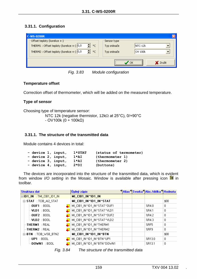
3.31. C-WS-0200R
159 TXV 004 13.02 .
3.31.1. Configuration
Fig. 3.83 Module configuration
Temperature offset Correction offset of thermometer, which will be added on the measured temperature. Type of sensor Choosing type of temperature sensor:
NTC 12k (negative thermistor, 12k at 25°C), 0/+90°C - OV100k (0 ÷ 100kΩ)
3.31.1. The structure of the transmitted data
Module contains 4 devices in total:
- device 1, input, 1*STAT (status of termometer)
- device 2, input, 1*AI (thermometer 1)
- device 3, input, 1*AI (thermometer 2)
- device 4, input, 2*DI (buttons)
The devices are incorporated into the structure of the transmitted data, which is evident from window I/O setting in the Mosaic. Window is available after pressing icon in toolbar.
Fig. 3.84 The structure of the transmitted data

CIB UNITS, MODULES
TXV 004 13.02 160
Input data
STAT THERM1 THERM2 BTN
STAT - status byte of analog inputs (8x type bool)
- - - - VLD2 OUF2 VLD1 OUF1
Bit .7 .6 .5 .4 .3 .2 .1 .0
OUF1 - overflow / underflow of range of temperature input 1 VLD1 - reading validity of temperature input 1 OUF2 - overflow / underflow of range of temperature input 2 VLD2 - reading validity of temperature input 2 THERM1 - value of analog/temperature input (type real) [°C],[kΩ] THERM2 - value of analog/temperature input (type real) [°C],[kΩ] The value of temperature sensor is transferred in °C (with resolution of
0.1°C), the value of general resistance in range 100kΩ is transferred in kΩ (with resolution of 10Ω).
BTN - status of buttons (8x type bool)
- - - - DOWN1 UP1
Bit .7 .6 .5 .4 .3 .2 .1 .0
UP1 - status of button UP DOWN1 - status of button DOWN

3.32. C-WS-0400R
161 TXV 004 13.02 .
3.32. C-WS-0400R
Wall switch module contains 4 short stroke buttons. The module can also connect 2 external temperature sensor to measure the ambient or any other temperature. Module is designed for Time and Element designs of ABB production. For actual offer of designs see the catalogue of Teco
The module is mechanically adapted for mounting on a standard installation flush box with a pitch of 60 mm fixing screws. Connection terminals for connection to the CIB bus and for external temperature sensors on the back side of the module.
Tab. 3.32 Basic parameters C-WS-0400R
Fig. 3. 85 View and connection example
Binary inputs
Quantity 4 Type short stroke button Temperature inputs
Quantity 2
External sensor type thermistor NTC 12kΩ(TC,TZ)
Range 0 ÷ +90 °C
Accuracy 1 °C
External sensor type resistance input 0 ÷ 100kΩ
Power supply
Power supply and communication
24 V (27 V) from the CIB
Nominal power consumption
20 mA
Galvanic isolation No
Dimensions and weight
Dimensions1)
88 × 81 × 21mm
Weight 60 g
Operating and installation conditions
Operating temperature -10 ÷ +55 °C
Storage temperature -25 ÷ +70 °C
IP degree of protection acc. IEC 529
IP10B
Degree of pollution EN 60664
1
Operating position Vertical
Type of operation Continuous
Installation Into the flush box
Connecting screw type terminals
Cross-section of wires max. 1,5 mm2
1) Dimensions according the specifics of used design..

CIB UNITS, MODULES
TXV 004 13.02 162
3.32.1. Configuration
Fig. 3.86 Module configuration
Temperature offset Correction offset of thermometer, which will be added on the measured temperature. Type of sensor Choosing type of temperature sensor:
NTC 12k (negative thermistor, 12k at 25°C), 0/+90°C - OV100k (0 ÷ 100kΩ)
3.32.2. The structure of the transmitted data
Module contains 4 devices in total:
- device 1, input, 1*STAT (status of termometer)
- device 2, input, 1*AI (thermometer 1)
- device 3, input, 1*AI (thermometer 2)
- device 4, input, 4*DI (buttons)
The devices are incorporated into the structure of the transmitted data, which is evident from window I/O setting in the Mosaic. Window is available after pressing icon in toolbar.
Fig. 3.87 The structure of the transmitted data

3.32. C-WS-0400R
163 TXV 004 13.02 .
Input data
STAT THERM1 THERM2 BTN
STAT - status byte of analog inputs (8x type bool)
- - - - VLD2 OUF2 VLD1 OUF1
Bit .7 .6 .5 .4 .3 .2 .1 .0
OUF1 - overflow / underflow of range of temperature input 1 VLD1 - reading validity of temperature input 1 OUF2 - overflow / underflow of range of temperature input 2 VLD2 - reading validity of temperature input 2 THERM1 - value of analog/temperature input (type real) [°C],[kΩ] THERM2 - value of analog/temperature input (type real) [°C],[kΩ] The value of temperature sensor is transferred in °C (with resolution of
0.1°C), the value of general resistance in range 100kΩ is transferred in kΩ (with resolution of 10Ω).
BTN - status of buttons (8x type bool)
- - - - DOWN2 UP2 DOWN1 UP1
Bit .7 .6 .5 .4 .3 .2 .1 .0
UP1 - status of button UP1 DOWN1 - status of button DOWN1 UP2 - status of button UP2 DOWN2 - status of button DOWN2

CIB UNITS, MODULES
TXV 004 13.02 164
3.33. C-WS-0200R-Logus
Wall switch module contains two short stroke buttons, 2 LED indicators and internal thermometr. The module can also connect 2 external temperature sensor to measure the ambient or any other temperature. The module also includes 2 universal DI/AI inputs that can be configured for connection another switching buttons or to connect other analog sensors. The module is designed in a design you LOGUS.
The module is mechanically adapted for mounting on a standard installation flush box with a pitch of 60 mm fixing screws. Connection terminals for connection to the CIB bus and for external temperature sensors on the back side of the module.

3.33. C-WS-0200R-Logus
165 TXV 004 13.02 .
Tab. 3.33 Basic parameters C-WS-0200R-Logus
red (rudá)
black (černá)
white (bílá)
white (bílá)
grey (šedá)
grey (šedá)
Fig. 3. 88 View and connection example
Buttons
Quantity 2 Type short stroke button LED indicators
Quantity 2 + 1
Colour 1x red, 1x green + 1x green RUN
Internal thermometer
Sensor type thermistor NTC 12kΩ
Range -10 ÷ +55 °C
Accuracy ± 1°C
Temperature settling time
150 minutes
Universal DI/AI inputs
Quantity 2
Optional types of inputs Binary, Pt1000, Ni1000, NTC12kΩ, KTY81-121, resistance 100kΩ, voltage input
Binary input NO potential-free contact
Pt1000 –90 ÷ +320 °C
Ni1000 –60 ÷ +200 °C
NTC 12kΩ –40 ÷ +125 °C
KTY81-121 –55 ÷ +125 °C
Resistance input 0 ÷ 100kΩ
Voltage input 0 ÷ 2V
Accuracy ± 1°C
Period of refresh AI typically 5s
Power supply
Power supply and communication
24 V (27 V) from the CIB
Nominal power consumption
15 mA
Galvanic isolation No
Dimensions and weight
Dimensions 86 × 86 × 38mm
Weight 79 g
Operating and installation conditions
Operating temperature -10 ÷ +55 °C
Storage temperature -25 ÷ +70 °C
IP degree of protection acc. IEC 529
IP10B
Degree of pollution dle EN 60664
1
Operating position Vertical
Type of operation Continuous
Installation Into the flush box
Connecting wires 0.5mm2, 90 mm

CIB UNITS, MODULES
TXV 004 13.02 166
3.33.1. Configuration
Fig. 3.89 Module configuration
The input terminals DI/AIx are shared for binary and analog inputs (for digital and
analog equipment). As the input is configured as analog one, it is not possible use it as binary input in the same time. Depending on the configured input (as enabled devices) specific items of configuration dialog are enabled/disabled. Enabling devices see. chap. 2.1 Master configuration, check the box Show units, devices
Delay, evaluation of long press For binary (momentary button) inputs module directly evaluate the short and long
presses on each input. By entering values one can set a delay time after which the activation of digital input DI is signalled as the long press (PRESS). Activating the digital input for period shorter than the entered value will be signalled by as the short press (CLICK). Delay period (Tpress) can be inserted in the range 0.1÷2.5s.
Fig. 3. 90 Evaluation of short/long press
Type of input Choosing the type of analog input:
Pt1000, W100 = 1,385, -90/+320°C Pt1000, W100 = 1,391, -90/+320°C Ni1000, W100 = 1,617, -60/+200°C Ni1000, W100 = 1,500, -60/+200°C

3.33. C-WS-0200R-Logus
167 TXV 004 13.02 .
NTC 12k (negative thermistor, 12k at 25°C), -40/+125°C KTY 81-121, -55/+125°C OV100k (0 ÷ 100kΩ) O ÷ 2V
Input filtering By specifying a non-zero value of the time constant, the 1st order digital filter is
activated. The filter is given by
1
1
xyy t
t
x - the current value of the analog input yt - output yt-1 - recent output time constant of the 1st order filter (TAU) - ح
Value of time constant is set in the range 0.1 ÷ 25.4 and it represents a time constant in the range of 100 ms ÷ 25.4 s (value 255 is intended for service purposes).
Temperature offset Correction offset of internal thermometer, which will be added on the measured
temperature of internal thermometer. 3.33.2. The structure of the transmitted data
Module contains 5 devices in total:
- device 1, input/output, 2*BUTT+2*DI/2*LED
- device 2, input, 1*STAT (status of analog inputs)
- device 3, input, 1*AI (internal thermometer)
- device 4, input, 1*AI (AI1)
- device 5, input, 1*AI (AI2)
The devices are incorporated into the structure of the transmitted data, which is evident from window I/O setting in the Mosaic. Window is available after pressing icon in toolbar.

CIB UNITS, MODULES
TXV 004 13.02 168
Fig. 3.91 The structure of the transmitted data
Input data
DI STAT THERM AI1 AI2
DI - current status of the buttons and binary inputs, short and long pulses (24x type bool) UPx - status of button UPx DOWNx - status of button DOWNx DIx - current status on the binary input x CLICK_x - short pulse (to log. 1) on the binary input (button) PRESSx - long pulse (into log. 1) on the binary input (button) STAT - status byte of analog inputs (8x type bool)
- - VLD2 OUF2 VLD1 OUF1 iVLD iOUF
Bit .7 .6 .5 .4 .3 .2 .1 .0
iOUF - overflow / underflow of internal thermometer range iVLD - internal thermometer reading validity OUFx - overflow / underflow of range of analog input AIx VLDx - validity of reading of analog input AIx iTHERM - value of internal thermometer (type real) [°C] AI1 - value of analog input 1 (type real) [°C],[kΩ]

3.33. C-WS-0200R-Logus
169 TXV 004 13.02 .
AI2 - value of analog input 2 (type real) [°C],[kΩ] The value of temperature sensor is transferred in °C (with resolution of
0.1°C), the value of general resistance in range 100kΩ is transferred in kΩ (with resolution of 10Ω).
Output data
LED
LES - value of LED outputs (8x type bool)
- - - - RED2 GREEN2 RED1 GREEN1
Bit .7 .6 .5 .4 .3 .2 .1 .0
GREEN1 - output value of green LED RED1 - output value of red LED

CIB UNITS, MODULES
TXV 004 13.02 170
3.34. C-WS-0400R-Logus
Wall switch module contains 4 short stroke buttons, 4 LED indicators and internal thermometr.The module also includes 2 universal DI/AI inputs that can be configured for connection another switching buttons or to connect other analog sensors. The module is designed in a design you LOGUS.
The module is mechanically adapted for mounting on a standard installation flush box with a pitch of 60 mm fixing screws. Connection terminals for connection to the CIB bus and for external temperature sensors on the back side of the module.

3.34. C-WS-0400R-Logus
171 TXV 004 13.02 .
Tab. 3.34 Basic parameters C-WS-0400R-Logus
red (rudá)
black (černá)
white (bílá)
white (bílá)
grey (šedá)
grey (šedá)
Fig. 3. 92 View and connection example
Buttons
Quantity 4 Type short stroke button LED indicators
Quantity 4 + 1
Colour 2x red, 2x green + 1x green RUN
Internal thermometer
Sensor type thermistor NTC 12kΩ
Range -10 ÷ +55 °C
Accuracy ± 1°C
Temperature settling time
150 minutes
Universal DI/AI inputs
Quantity 2
Optional types of inputs Binary, Pt1000, Ni1000, NTC12kΩ, KTY81-121, resistance 100kΩ, voltage input
Binary input NO (normaly open) potential-free contact
Pt1000 –90 ÷ +320 °C
Ni1000 –60 ÷ +200 °C
NTC 12kΩ –40 ÷ +125 °C
KTY81-121 –55 ÷ +125 °C
Resistance input 0 ÷ 100kΩ
Voltage input 0 ÷ 2V
Accuracy ± 1°C
Period of refresh AI typically 5s
Power supply
Power supply and communication
24 V (27 V) from the CIB
Nominal power consumption
15 mA
Galvanic isolation No
Dimensions and weight
Dimensions 86 × 86 × 38mm
Weight 79 g
Operating and installation conditions
Operating temperature -10 ÷ +55 °C
Storage temperature -25 ÷ +70 °C
IP degree of protection acc. IEC 529
IP10B
Degree of pollution dle EN 60664
1
Operating position Vertical
Type of operation Continuous
Installation Into the flush box
Connecting wires 0.5mm2, 90 mm
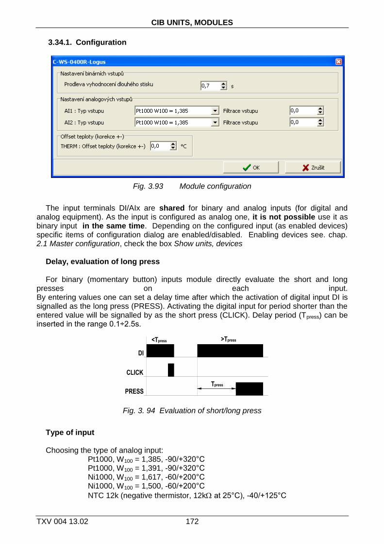
CIB UNITS, MODULES
TXV 004 13.02 172
3.34.1. Configuration
Fig. 3.93 Module configuration
The input terminals DI/AIx are shared for binary and analog inputs (for digital and
analog equipment). As the input is configured as analog one, it is not possible use it as binary input in the same time. Depending on the configured input (as enabled devices) specific items of configuration dialog are enabled/disabled. Enabling devices see. chap. 2.1 Master configuration, check the box Show units, devices
Delay, evaluation of long press For binary (momentary button) inputs module directly evaluate the short and long
presses on each input. By entering values one can set a delay time after which the activation of digital input DI is signalled as the long press (PRESS). Activating the digital input for period shorter than the entered value will be signalled by as the short press (CLICK). Delay period (Tpress) can be inserted in the range 0.1÷2.5s.
Fig. 3. 94 Evaluation of short/long press
Type of input Choosing the type of analog input:
Pt1000, W100 = 1,385, -90/+320°C Pt1000, W100 = 1,391, -90/+320°C Ni1000, W100 = 1,617, -60/+200°C Ni1000, W100 = 1,500, -60/+200°C
NTC 12k (negative thermistor, 12k at 25°C), -40/+125°C

3.34. C-WS-0400R-Logus
173 TXV 004 13.02 .
KTY 81-121, -55/+125°C OV100k (0 ÷ 100kΩ) O ÷ 2V
Input filtering By specifying a non-zero value of the time constant, the 1st order digital filter is
activated. The filter is given by
1
1
xyy t
t
x - the current value of the analog input yt - output yt-1 - recent output time constant of the 1st order filter (TAU) - ح
Value of time constant is set in the range 0.1 ÷ 25.4 and it represents a time constant in the range of 100 ms ÷ 25.4 s (value 255 is intended for service purposes).
Temperature offset Correction offset of internal thermometer, which will be added on the measured
temperature of internal thermometer. 3.34.2. The structure of the transmitted data
Module contains 5 devices in total:
- device 1, input/output, 4*BUTT+2*DI/4*LED
- device 2, input, 1*STAT (status of analog inputs)
- device 3, input, 1*AI (internal thermometer)
- device 4, input, 1*AI (AI1)
- device 5, input, 1*AI (AI2)
The devices are incorporated into the structure of the transmitted data, which is evident from window I/O setting in the Mosaic. Window is available after pressing icon in toolbar.

CIB UNITS, MODULES
TXV 004 13.02 174
Fig. 3.95 The structure of the transmitted data
Input data
DI STAT THERM AI1 AI2
DI - current status of the buttons and binary inputs, short and long pulses (24x type bool) UPx - status of button UPx DOWNx - status of button DOWNx DIx - current status on the binary input x CLICK_x - short pulse (to log. 1) on the binary input (button) PRESSx - long pulse (into log. 1) on the binary input (button) STAT - status byte of analog inputs (8x type bool)
- - VLD2 OUF2 VLD1 OUF1 iVLD iOUF
Bit .7 .6 .5 .4 .3 .2 .1 .0

3.34. C-WS-0400R-Logus
175 TXV 004 13.02 .
iOUF - overflow / underflow of internal thermometer range iVLD - internal thermometer reading validity OUFx - overflow / underflow of range of analog input AIx VLDx - validity of reading of analog input AIx iTHERM - value of internal thermometer (type real) [°C] AI1 - value of analog input 1 (type real) [°C],[kΩ] AI2 - value of analog input 2 (type real) [°C],[kΩ] The value of temperature sensor is transferred in °C (with resolution of
0.1°C), the value of general resistance in range 100kΩ is transferred in kΩ (with resolution of 10Ω).
Output data
LED
LES - value of LED outputs (8x type bool)
- - - - RED2 GREEN2 RED1 GREEN1
Bit .7 .6 .5 .4 .3 .2 .1 .0
GREENx - output value of green LEDx REDx - output value of red LEDx

CIB UNITS, MODULES
TXV 004 13.02 176
3.35. RCM2-1
Module is designed for office and residential interiors. It is intended for display and setting of desired temperature as a Control Room Manager. It Includes LCD to display one digital value and variety of graphic icons used in heating, ventilation, air conditioning. To navigate in the menu and edit values the module contain a rotary element with confirmation (pressing).
Internal temperature sensor is integrated in the module. The module also contains one input for connecting an external NTC temperature sensor and binary SSR output (Solid State Relay for heating controls, etc.).
Tab. 3.35 Basic parameters RCM2-1
1
7 9
6 8
5
4
3
2 CIB+
THERM DOUT
THERM
TEPLOTNÍSENSOR
COM
CIB-
CIB-
--
CIB+
CIB -
CIB +
Fig. 3. 96 View and connection exampleRCM2-1
3.35.1. Configuration
Display
Type LCD (to display one value + graphic symbols)
Control element Roller with button
Analog input
Quantity 2
Type of input Temperature sensor (internal, external)
Sensor type Thermistor NTC 12k
Range -20 ÷ +100 °C
Accuracy 0,8 °C
Binary output
Quantity 1
Type SSR relay (Solid State Relay)
Galvanic isolation Yes, 1500V
Typical Voltage 24 V AC/DC (max. 60 V)
Max. current 600 mA
Power supply
Power supply and communication
24 V (27 V) from the CIB
Nominal power consumption
17mA
Dimensions and weight
Dimensions 90 × 115 × 39mm
Weight 130g
Operating and installation conditions
Operating temperature 0 ÷ +60 °C
Storage temperature –30 ÷ +70 °C
Electrical strength according to EN 60950
IP degree of protection acc. IEC 529
IP 20
Overvoltage category III
Degree of pollution EN 61131-2
2
Operating position Arbitrary
Mechanical design Plastic box
Installation On wall, on flush box
Connecting screw type terminals
Cross-section of wires max. 1,5 mm2

3.35. RCM2-1
177 TXV 004 13.02 .
Fig. 3.97 Module configuration
Temperature offset
Correction offset of internal thermometer, which will be added on the measured temperature of internal thermometer.
3.35.2. The structure of the transmitted data
Module contains 5 devices in total:
- device 1, input, 3*DI (roller flags)
- device 2, output, DISP (values + symbols)
- device 3, input, 1*AI (internal thermometer)
- device 4, input, 1*AI (external thermometer)
- device 5, input, 1*AI (roller counter)
The devices are incorporated into the structure of the transmitted data, which is evident from window I/O setting in the Mosaic. Window is available after pressing icon in toolbar.
Fig. 3.98 The structure of the transmitted data

CIB UNITS, MODULES
TXV 004 13.02 178
Input data
FLG iTHERM eTHERM COUNTER
FLG - roller status (8x type bool) PRESS - roller pressed (function of button) LEFT - anti-clockvwise turning (when turning the value 1-0-1-0-…is
passed) RIGHT clockvwise turning (when turning the value 1-0-1-0-…is passed)
iTHERM - temperature of internal sensor (type real) [°C] eTHERM - temperature of external sensor (type real) [°C] COUNTER - cyclic counter of roller position (type sint)
Output data
VALUE ERROR ICO
VALUE - value to be displayed on the main 7-segment display (type int) the value displayed depends on visibility segments S1 - S2 and D1 - D4 ERROR - value to be displayed on side 7-segment display (type usint) the value displayed depends on visibility segment D5 ICO - flags to control visibility of symbols / segments on display, binary output (48* type bool) (see folloving figure and table)

3.35. RCM2-1
179 TXV 004 13.02 .
Fig. 3. 99 Layout of symbols and segments on display RCM2-1
Icon / segment Symbolic name
T1 ONE
T2 TWO
T3 THREE
T4 FOUR
T5 FIVE
T6 SIX
T7 SEVEN
P3 ERROR
P2 No
T8 Clock
T12 Moon
T13 Sun
T10 House
T11 Figure
T15 Drink
T9 Thermometer
T14 Power
P1 Setting
S3 Celsius
S4 Fahrenheit
P6 Percent
W1 rH
P5 dotUp
P4 dotDown
P7 Heating
P8 Cooling
S5 Ventilation
P9 Water
P10 Spanner
P11 P11
P12 Bell
W2 Manual
P13 LN3
P14 LN2
P15 LN1
P16 Rotation
P17 LP1
P18 LP2
P19 LP3
P20 Automatic
S1 Minus
S2 S2
D1 D1
D2 D2
D3 D3
D4 D4
D5 DE
binary output DOUT

Attachments
TXV 004 13.02 180
4. Attachments
Attachment 1 Order codes of CIB modules.
Module identification Order number
I MI2-02M TXN 131 28
II CF-1141 TXN 111 41
1 C-AM-0600I TXN 133 50
2 C-AQ-0001R TXN 133 12
3 C-AQ-0002R TXN 133 13
4 C-AQ-0003R TXN 133 14
5 C-AQ-0004R TXN 133 15
6 C-DL-0012S TXN 133 23
7 C-DL-0064M TXN 133 54
8 C-DM-0006M-ILED TXN 133 46
9 C-DM-0006M-ULED TXN 133 45
10 C-DM-0402M-RLC TXN 133 58
11 C-HC-0201F-E TXN 133 48
12 C-HM-0308M TXN 133 24
13 C-HM-1113M TXN 133 10
14 C-HM-1121M TXN 133 11
15 C-IB-1800M TXN 133 06
16 C-IR-0202S TXN 133 25
17 C-IR-0203M TXN 133 59
18 C-IT-0100H-A TXN 133 17
19 C-IT-0100H-P TXN 133 16
20 C-IT-0200I TXN 133 09
21 C-IT-0200R TXN 133 19
22 C-IT-0200S TXN 133 29
23 C-IT-0504S TXN 133 26
24 C-IT-0908S TXN 133 52
25 C-OR-0008M TXN 133 03
26 C-OR-0202B TXN 133 02
27 C-RC-0002R TXN 133 33
28 C-RC-0003R TXN 133 37
29 C-RI-0401S TXN 133 47
30 C-WG-0503S TXN 133 53
31 C-WS-0200R TXN 133 30
32 C-WS-0400R TXN 133 31
33 C-WS-0200R-Logus TXN 133 56
34 C-WS-0400R-Logus TXN 133 57
35 RCM2-1 TXN 131 57

Notes
181 TXV 004 13.02 .
Notes

Notes
TXV 004 13.02 182
Notes

.
Objednávky a informace:
Teco a. s. Havlíčkova 260, 280 58 Kolín 4, tel. 321 737 611, fax 321 737 633
TXV 004 13.01
The manufacturer reserves the right to change the documentation. The last issue is available on the Internet
www.tecomat.cz.