Performance Standards and Test Procedures for Continuous ... · in a separate MCERTS performance...
72
Performance Standards and Test Procedures for Continuous Emission Monitoring Systems (CEMs) and Transportable-CEMs (T-CEMs) For gaseous, particulate and flow-rate monitoring systems Environment Agency July 2018 Version 4
Transcript of Performance Standards and Test Procedures for Continuous ... · in a separate MCERTS performance...
Performance Standards and Test Procedures for Continuous Emission Monitoring Systems (CEMs) and Transportable-CEMs (T-CEMs)
For gaseous, particulate and flow-rate monitoring systems
Environment Agency July 2018 Version 4

Record of amendments
Version
number Date Section Amendment
3.5 February 2016 Foreword Reference to EN ISO/IEC 17065 in lieu of EN 45011. Updated address for CSA-Sira.
3.5 February 2016 1.1 Added references to EN 16911-2, EN 15859 and the Industrial Emissions Directive (IED) (2010/75/EU); plus editorial changes.
3.5 February 2016 1.4 Added references to EN 14181 and EN ISO 16911-2 regarding the validity of certificates.
3.5 February 2016 1.5 Updated references to the IED within the scope. Removal of outdated legislation.
3.5 February 2016 2 Updated the table of normative references, to include updated standards, the addition of EN ISO 16911-2 and the removal of EN 15256.
3.5 February 2016 6.2 Revised references to the new Directives for electromagnetic compatibility and low voltages.
3.5 February 2016 8.3, Table 4 Correction of a typographical error.
3.5 February 2016 8.4 Addition of Table 6b to provide for the supplementary requirements of EN ISO 16911-2 for flow-monitoring CEMs.
3.5 February 2016 10.4 Updated reference to the IED.
3.5 February 2016 10.22 Deletion of reference to EN 13526.
3.5 February 2016 Annex A Amendments to updates references to standards.
3.5 February 2016 Annex G References to legislation updated; outdated legislation removed and reference added for IED.
3.5 February 2016 Bibliography References to legislation and standards updated.
4 July 2018 Foreword References to T-CEMs (EN 15267-4) and the distinction between T-CEMs and Handheld Emissions Monitoring Systems (HEMS).
4 July 2018 1.1 Reference to EN 15267-4 and its context.
4 July 2018 1.2-1.5 Further division into sub-sections with additional clarification.
4 July 2018 1.9 Addition of a taxonomy showing the roles of CEMs, T-CEMs and HEMs for measuring emissions from medium to large combustion-plants.
4 July 2018 2 Addition of EN 14793, EN 15267-4, EN ISO/IEC 17021-1 and EN ISO/IEC 17065 to the normative references.
4 July 2018 3 Addition of a note to definition number 3.4 to show equivalence of P-AMS and T-CEMs.
4 July 2018 Annex F Revision of the Annex, aligning it with the requirements of EN 15267-4.

Status of this document
This document may be subject to review and amendment following publication. The latest version is available on our website at: www.mcerts.net
Feedback If you have any comments on this document, please contact our National Customer
Contact Centre at:
Email: [email protected]
Tel: +44 (0) 3708 506 506
i
Foreword We set up our Monitoring Certification Scheme (MCERTS) to provide guidelines on the standards you need to meet to monitor things that affect the environment. MCERTS covers:
the standards your monitoring equipment must meet
how qualified your staff must be
recognising laboratories and inspecting sites in line with European and international standards
This document describes the performance requirements and certification process for Continuous Emission Monitoring systems (CEMs) and their transportable counterparts, Transportable-CEMs (T-CEMs). CEMs and T-CEMs are systems used to measure the concentrations of gases and particles in an environment where there are industrial chimney stacks and flues and ducts. They often do this in lots of different working conditions, because conditions vary from site to site. This MCERTS performance standard does not apply to highly-portable, Handheld Emissions Monitoring systems (HEMs). This type of system includes the following: compact emissions-monitoring systems designed for small combustion plant, typically from 1MW to 20MW by thermal-input capacity; landfill-gas monitoring systems, and; fugitive emissions monitoring systems such as those required when using USEPA Method 21 and EN 15446. The standards for HEMs are described in a separate document, MCERTS performance standards and test requirements for Handheld Emissions Monitoring Systems (HEMs). MCERTS for CEMs and T-CEMs is an official certification scheme that falls under the European Standard EN ISO/IEC 17065. CSA Group, the certification body in this document, runs this scheme for us. CEMs and T-CEMs must be tested by laboratories and test organisations that have EN ISO/IEC 17025, which is the internationally recognised standard for testing laboratories. CSA-Group examines the results of the laboratory tests and field tests using a group of independent experts known as the Certification Committee. The benefits of this standard
The standard gives you the support of a certification scheme that is officially recognised in the UK and is accepted internationally.
Regulators can be confident that monitoring equipment which meets the standard gives them reliable information about emissions.
You can be confident that the equipment you use to monitor emissions has been thoroughly tested and meets standards that are accepted by UK regulators.
The standard gives manufacturers an independent approval. This means people will trust their products, which will improve sales in the UK and internationally.
The standard helps make sure the public get accurate and reliable information about the quality of air.
ii
If you have any questions about the how the certification process works, or you would
like more information on how to apply, please contact CSA-Group using the details
below.
Sira Certification Service CSA Group Unit 6 Hawarden Industrial Park Hawarden CH5 3US Phone: +44-1244 670 900 E-mail: [email protected] If you have any general questions about MCERTS, please contact us. Email: [email protected] Tel: +44 (0) 3708 506 506 You can get more information on MCERTS, including the standards related to CEMs, from our website at www.mcerts.net.
iii
Contents
1 Introduction 1
2 Normative references 7
3 Terms and definitions 8
4 Symbols and abbreviations 12
5 General requirements 13
6 Performance criteria common to all CEMs for laboratory testing 15
7 Performance criteria common to all CEMs for field testing 18
8 Performance criteria specific to measured components 19
9 General test requirements 25
10 Test procedures for laboratory tests 26
11 Requirements for field tests 39
12 Test procedures common to all CEMs for field tests 40
13 Test procedures for particulate-monitoring CEMs 46
14 Measurement uncertainty 47
15 Test report 47
Annex A — Standard reference methods 48
Annex B — Interferents 49
Annex C — Test for lack-of-fit 50
Annex D — Determination of uncertainties for QAL1 52
Annex E — Template for a performance testing report 58
Annex F — Transportable systems 60
Annex G — Classes of particulate monitoring CEMs and their allowable uses 62
Annex H — Calibration of Class 2 and Class 3 particulate monitors 63
Bibliography 65

iv
MCERTS Performance Standards for CEMs and T-CEMs, Version 4, July 2018 1 of 62
Performance Standards and Test Procedures for Continuous Emission Monitoring Systems
1 Introduction
1.1 Background
This document describes the performance standards, test procedures and general requirements for the testing of continuous emission monitoring systems (CEMs) under MCERTS in compliance with CEN standards EN 15267-3 and EN 15267-4, with additional provisions for testing and certification to EN ISO 16911-2 for flow-monitors. This latter standard includes extra requirements to EN 15267-3 and therefore provides additional assurance to users of flow-monitoring CEMs if required. CEN developed EN 15267-3 to provide for the QAL1 and QAL3 requirements of EN 14181 and now provides a means of demonstrating compliance with the uncertainty requirements specified in the Industrial Emissions Directive (2010/75/EU). CEN developed EN 15267-4 to provide performance-requirements for transportable CEMs (T-CEMs). Manufacturers have developed such systems for use within Standard Reference Methods (SRMs) for compliance monitoring and for the QAL2/AST requirements of EN 14181. Annex F describes the performance requirements for T-CEMs. The requirements for certification are covered in BS EN 15267-1, and the requirements for the manufacturer’s quality-management system for manufacturing and design control are covered in BS EN 15267-2. The determinands covered include, but are not restricted to:
sulphur dioxide (SO2)
oxides of nitrogen (principally NO and NO2, but also N2O)
carbon monoxide (CO) and carbon dioxide (CO2)
hydrogen chloride (HCl)
hydrogen fluoride (HF)
methane (CH4)
sulphur hexafluoride (SF6)
hydrofluorocarbons (HFCs) and perfluorocarbons (PFCs)
mercury (Hg)
formaldehyde
benzene
volatile organic compounds, expressed as total organic carbon (TOC)
oxygen (O2)
water vapour (H2O)
particulate matter, for installations which must comply with the requirements of EN 14181
flow rate The performance standards cover a range of emission levels for waste incineration, solvent-using processes, large combustion plant (including gas turbines), as well as other types of installation specified in the IED. The general requirements and performance standards for all CEMs for each characteristic are specified in Section 5, whilst the performance criteria for CEMs are covered in Sections 6, 7 and 8. The requirements for testing to evaluate the performance of CEMs for compliance with the MCERTS performance standards are specified in Sections 9, 10, 11, 12 and 13.

MCERTS Performance Standards for CEMs and T-CEMs, Version 4, July 2018 2 of 62
1.2 Classes of CEM for total particulate matter Additionally, there are three classes of particulate monitor. These are:
Class 1: Particulate monitors used for measuring emissions in mg. m-3. Class 1 monitors meet the requirements of EN 15267-3 and EN 14181, specifically for QAL1 and QAL3. Operators of large combustion plant and incinerators falling under Chapters III and IV respectively of the IED must use Class 1 particulate monitors. Class 1 monitors may also be used on all other PPC installations.
Class 2: Particulate monitors, also known as filter dust-monitors, used for measuring emissions in mg.m-3. Class 2 monitors may be used with our agreement on PPC installations other than large combustion plant and incineration where the emissions are normally less than 50% of the emission limit value. Such monitors are used to provide feedback that a process is under control and stable and operating well within the emission limit value. Class 2 monitors meet the requirements of EN 15859 instead of those specified in EN 15267-3.
Class 3: Filter leakage-monitors, used to monitor changes in performance of dust-arrestment plant and alarm in the event of failure. They provide an indication of particulate emissions but do not measure emissions in mg.m-3.
Annex G shows the classes of particulate monitor and their allowable uses. Class 1 particulate monitors must have the means to measure and record zero and span drift, in order to meet the requirements of QAL3 in EN 14181. Classes 2 and 3 must have a means of measuring the stability of the CEM, using internal zero and reference points, but do not have to meet the QAL3 requirements of EN 14181. This document only covers the requirements for Class 1 particulate monitors. Class 2 and Class 3 particulate monitors are required to meet the requirements of EN 15859 instead of those specified in EN 15267-3.The requirements for Class 2 and Class 3 particulate monitors are covered in a separate MCERTS performance standard, the MCERTS performance standards for the Certification of automated dust arrestment-plant monitors – Performance criteria and test procedures, according to EN 15859. 1.3 Main performance-characteristics The main CEM performance characteristics against which a CEM will be assessed by a combination of laboratory and field testing are:
lack-of-fit, (linearity)
cross-sensitivity to likely components of the stack gas other than the determinand
influence of sample pressure and sample temperature
response time
detection limit (repeatability at zero)
repeatability at span
influence of ambient conditions on zero and span readings
performance and accuracy under field conditions
reproducibility under field conditions
availability and maintenance interval under field conditions
time-dependent zero and span drift under field conditions
susceptibility to physical disturbances
design features

MCERTS Performance Standards for CEMs and T-CEMs, Version 4, July 2018 3 of 62
1.4 Phases of product certification Product certification comprises three phases. These are:
Laboratory testing – used to determine performance characteristics, where such testing requires a highly controlled environment.
Field testing – which must be at least three months long. The field test is carried out on processes representative of the intended industrial sectors and applications.
Surveillance – initial and continuing – which comprises an audit of the manufacturing process to confirm that the manufacturer has provisions to ensure manufacturing reproducibility and to control any design changes to ensure that they do not degrade performance below the MCERTS standards.
Test laboratories shall have accredited procedures that comply with the requirements of EN ISO/IEC 17025, EN 15267-3 and the requirements of the MCERTS scheme. EN 15267-1 describes the roles and responsibilities of all parties involved in testing and certification, whilst EN 15267-2 describes the requirements for the quality assurance of the manufacturing and design processes. Therefore EN 15267-2 applies primarily to manufacturers of CEMs.
1.5 Manufacturing, repairs, maintenance and modifications to certified CEMs
Any spares or replacement parts for certified CEMs must meet the same performance standards as the original parts. Operators and equipment suppliers may be required to provide evidence that the replacement parts meet the required performance standards of the original equipment as specified by the CEM manufacturer. Modifications to certified CEMs are allowable so long as manufacturers can demonstrate that these design changes do not degrade the performance of the CEM below the MCERTS performance standards. Manufacturers must have a management system which meets the requirements of EN 15267-2. This standard requires manufacturers to keep detailed records and drawings of all design changes to CEMs, and have provisions for design verification, inspection and testing to ensure that the CEMs still meet the required performance standards. A suitably accredited certification-body will conduct audits of the design changes to CEMs to meet the requirements of product certification. Manufacturers must notify the Certification Body of any modifications to equipment that may have a significant effect on CEM performance. EN 15267-2 provides details of the audit and certification requirements for the manufacturer’s management system. Design modifications or extensions to the range of application of a CEM may require renewed testing. The extent of this renewed testing will depend upon the nature of the modifications to the CEM. If there is evidence that a modification has only limited effects on the performance of the CEM, then it would not be necessary to retest a CEM completely. In such cases, only a supplementary test would be required to the applicable MCERTS performance standards. In the case of modifications to software – particularly in measuring instruments –documentation must be presented to the Certification Body indicating the nature of the modification as well as resultant effects on operation and functionality. The Certification Body will then decide if further testing is required. A CEM is certified with a specified type of sampling system. If the analyser is used with components for the sampling system which differ from those which were originally tested, there must be verifiable evidence from a suitable third party test laboratory to demonstrate that the alternative sampling system still enables the CEM to meet the MCERTS performance requirements.

MCERTS Performance Standards for CEMs and T-CEMs, Version 4, July 2018 4 of 62
Note: The requirements for certification are covered in BS EN 15267-1, and the requirements for the manufacturer’s quality-management system for manufacturing and design control are covered in BS EN 15267-2. The certification body applies the requirements of these standards.
1.6 Previous performance-tests
Manufacturers that have test reports to demonstrate compliance with the requirements of the UBA’s type-approval scheme for their CEMs are invited to submit test reports along with their application for MCERTS certification. We have a formal procedure, MCERTS - Guidance on the Acceptance of German Type Approval Test Reports for CEMs, for assessing the test results for compliance with the MCERTS performance standards. Figure 1 shows the process for assessing previous test-results.
Note: Test reports produced to demonstrate compliance with other national schemes may also be acceptable.
Figure 1 – Process for the assessment of existing test-data
1.7 Certificate validity
Certificates are valid indefinitely, subject to a five-yearly review and the satisfactory control of manufacturing processes and design changes, and compliance with the requirements of BS EN 15267-1, BS EN 15267-2, BS EN 15267-3; and EN ISO 16911-2/EN 14181 if applicable. The certification body keeps the validity of the certification of the CEM under continuous appraisal, taking into account the reports from technical changes to the CEM, post-certification surveillance as defined in BS EN 15267-1, any changes in the technical requirements notified by the Environment Agency, and any complaints from users.
1.8 Scope
The scope of processes within the MCERTS scheme for CEMs is as follows:
Incineration processes, including those for hazardous waste, co-incineration, sewage sludge,
Receipt of application
Determining scope and
application of EN
performance-standards
Determine whether tests
met the requirements of
current standards and
EN ISO/IEC 17025
Complete retesting
against applicable EN
standard
Are there missing or
incomplete test-results?
Partial retesting against
applicable EN standard
NO
YES
Perform a gap analysis
against the applicable
EN standards
Proceed to next stage of
certification process
NO
YES
MCERTS Performance Standards for CEMs and T-CEMs, Version 4, July 2018 5 of 62
municipal waste and clinical waste. In short, those processes covered by Chapter IV of the Industrial Emissions Directive (2010/75/EU).
Combustion processes covered by Chapter III of the Industrial Emissions Directive (2010/75/EU).
Solvent-using processes covered by the Chapter V of the Industrial Emissions Directive (2010/75/EU).
Gas-fired turbines covered by Chapter III of the Industrial Emissions Directive (2010/75/EU). There is evidence that gas turbines are highly specialised and demanding applications for monitoring, particularly regarding the measurement of low concentrations of oxides of nitrogen.
Note: CEMs for gas turbines need to monitor nitric oxide and nitrogen dioxide at suitably low ranges.
Other activities listed in Annex I of the Industrial Emissions Directive (IED) (2010/75/EU).
Greenhouse gas emissions. Processes covered by the Directive establishing a scheme for greenhouse gas emission allowance trading within the Community and amending Council Directive 96/61/EC (2003/87/EC)(as amended).
CEMs will ordinarily be tested on a highly demanding process, such as a large coal-fired power station, municipal waste incinerator or a gas-fired turbine, depending on the intended application. The premise is that, if the CEM performs acceptably on these applications, then experience has shown that it will generally perform well on 95% of other processes. However, there will always be exceptions, and it is the responsibility of the manufacturer in conjunction with the user to ensure that the CEM will perform adequately on a specific process.
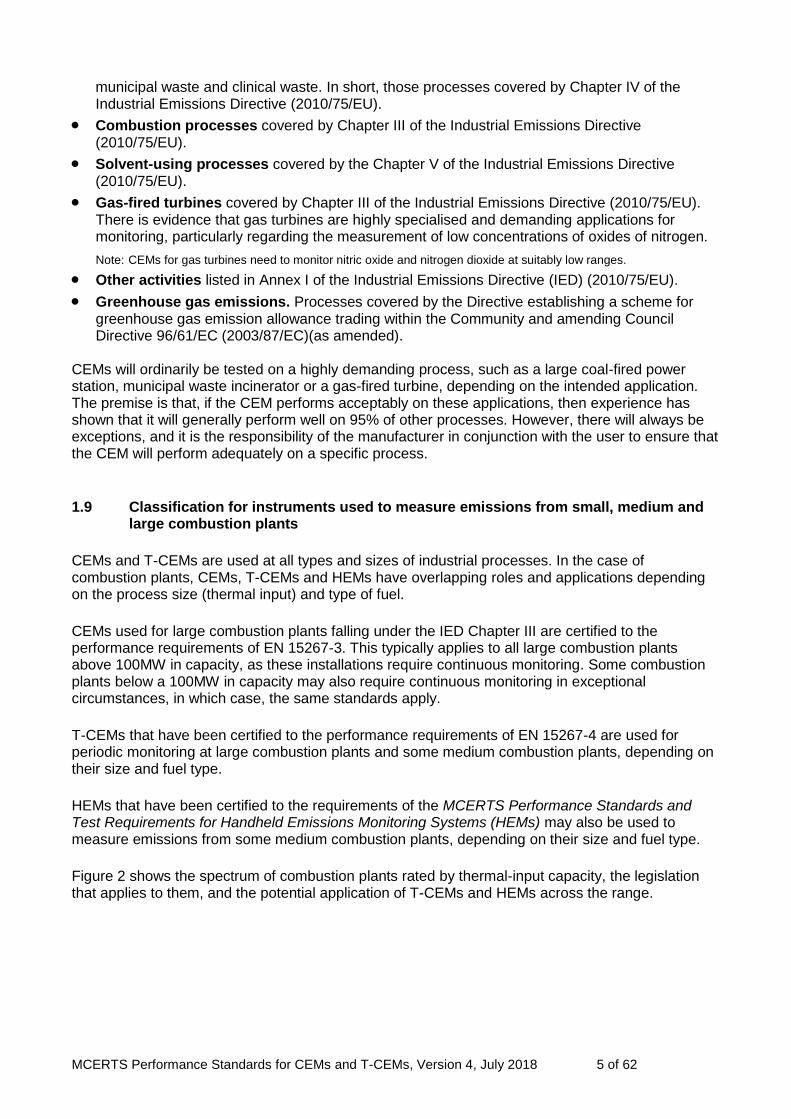
1.9 Classification for instruments used to measure emissions from small, medium and large combustion plants
CEMs and T-CEMs are used at all types and sizes of industrial processes. In the case of combustion plants, CEMs, T-CEMs and HEMs have overlapping roles and applications depending on the process size (thermal input) and type of fuel.
CEMs used for large combustion plants falling under the IED Chapter III are certified to the performance requirements of EN 15267-3. This typically applies to all large combustion plants above 100MW in capacity, as these installations require continuous monitoring. Some combustion plants below a 100MW in capacity may also require continuous monitoring in exceptional circumstances, in which case, the same standards apply.
T-CEMs that have been certified to the performance requirements of EN 15267-4 are used for periodic monitoring at large combustion plants and some medium combustion plants, depending on their size and fuel type.
HEMs that have been certified to the requirements of the MCERTS Performance Standards and Test Requirements for Handheld Emissions Monitoring Systems (HEMs) may also be used to measure emissions from some medium combustion plants, depending on their size and fuel type.
Figure 2 shows the spectrum of combustion plants rated by thermal-input capacity, the legislation that applies to them, and the potential application of T-CEMs and HEMs across the range.

MCERTS Performance Standards for CEMs and T-CEMs, Version 4, July 2018 6 of 62
Figure 2 – Application of T-CEMs and HEMs at combustion plants
<1MW >20MW - <50MW >50MW>1MW - <20MW
Medium Combustion Plant Directive IED Ch.3 - Large Combustion Plants
SmallCombustion
Plants
Transportable-CEMs toEN 15267-4
Handheld EmissionsMonitoring
Systems (HEMS)
Inst
rum
en
tsto
EN 5
03
79

MCERTS Performance Standards for CEMs and T-CEMs, Version 4, July 2018 7 of 62
2 Normative references
The following referenced documents are necessary for the application of this document. For dated references, only the edition cited applies. For undated references, the latest edition of the referenced document (including any amendments) applies.
EN 15267-1 Air quality - Certification of automated measuring systems - Part 1: General aspects.
EN 15267-2 Air quality - Certification of automated measuring systems - Part 2: Minimum requirements for product quality assurance, initial assessment and on-going surveillance.
EN 15267-3 Air quality — Certification of automated measuring systems — Part 3: Performance criteria and test procedures for automated measuring systems for monitoring emissions from stationary sources.
EN 15267-4 Air quality — Certification of automated measuring systems — Part 4: Performance criteria and test procedures for portable automated measuring systems for monitoring emissions from stationary sources.
EN 15859 Air quality - Certification of automated dust arrestment-plant monitors – Performance criteria and test procedures.
EN 12619 Stationary source emissions – Determination of the mass concentration of total gaseous organic carbon at low concentrations in flue gases – Continuous flame ionisation detector method.
EN 13284-1 Stationary source emissions – Determination of low range mass concentration of dust – Part 1: Manual gravimetric method.
EN 13284-2 Stationary source emissions – Determination of low range mass concentration of dust – Part 2: Automated measuring systems.
EN 14793 Stationary source emissions - Demonstration of equivalence of an alternative method with a reference method.
EN ISO 16911-2 Stationary source emissions – Manual and automatic determination of velocity and volume flow rate in ducts Part 2: Automated measuring systems.
EN 14181 Stationary source emissions – Quality assurance of automated measuring systems.
EN 15259 Air Quality – Measurement of stationary source emissions – Requirements for measurement sections and sites and for the measurement objective, plan and report.
EN 50160 Voltage characteristics of electricity supplied by public distribution systems.
EN 60529 Specification for degrees of protection provided by enclosures (IP code).
EN ISO 14956 Air quality – Evaluation of the suitability of a measurement method by comparison with a stated measurement uncertainty.
EN ISO/IEC 17025 General requirements for the competence of testing and calibration laboratories.
EN ISO/IEC 17021-1
Conformity assessment. Requirements for bodies providing audit and certification of management systems. Requirements
EN ISO 17065 Conformity assessment. Requirements for bodies certifying products, processes and services.

MCERTS Performance Standards for CEMs and T-CEMs, Version 4, July 2018 8 of 62
3 Terms and definitions
3.1 accuracy closeness of agreement between a single measured value of the measurand, and the true value (or an accepted reference value)
3.2 availability fraction of the total monitoring time for which data of acceptable quality have been collected
3.3 averaging time period of time over which an arithmetic or time-weighted average of concentrations is calculated
3.4 automated measuring system (CEM) entirety of all measuring instruments and additional devices for obtaining a result of measurement
Note 1: Apart from the actual measuring device (the analyser), a CEM includes facilities for taking samples (for example probe, sample gas lines, flow meters and regulator, delivery pump) and for sample conditioning (for example dust filter, pre-separator for interferents, cooler, converter). This definition also includes testing and adjusting devices that are required for functional checks and, if applicable, for commissioning.
Note 2: The term automated measuring system (AMS) is typically used in Europe. The term CEM for continuous emission monitoring system is also typically used in the UK and USA.
Note 3: EN 15267-4 refers to portable-AMS. These are called Transportable-CEMs in this document.
3.5 calibration determination of a calibration function with (time) limited validity applicable to a CEM at a specific measurement site
3.6 calibration function linear relationship between the values of the SRM and the CEM with the assumption of a constant residual standard deviation
Note: The calibration function describes the statistical relationship between the starting variable (measured signal) of the measuring system and the associated result of measurement (measured value) simultaneously determined at the same point of measurement using a SRM.
3.7 certification range range over which the CEM is tested and certified for compliance with the relevant performance criteria
Note: Certification range is always related to the daily ELV.
3.8 converter efficiency efficiency with which the converter unit of a NOx analyser reduces NO2 to NO
3.9 cross-sensitivity response of the CEM to determinands other than those that it is designed to measure
Note: See interference.
3.10 delay time time taken for the output signal of the CEM to reach 10 % of the total change in instrument response
3.11 drift monotonic change of the calibration function over a stated period of unattended operation, which results in a change of the measured value
3.12 emissions limit value (ELV) limit values given in EC Directives, ordinances, regulations, permits, licences, authorisations or consents

MCERTS Performance Standards for CEMs and T-CEMs, Version 4, July 2018 9 of 62
Note: ELV can be stated as concentration limits expressed as half-hourly, hourly and daily averaged values, or mass flow limits expressed as hourly, daily, weekly, monthly or annually aggregated values.
3.13 expanded uncertainty quantity defining an interval about the result of a measurement that may be expected to encompass a large fraction of the distribution of values that could reasonably be attributed to the measurand.
Note: The interval about the result of measurement is established for a level of confidence is typically 95 %.
3.14 field test test for at least three months on an industrial facility appropriate to the CEMs' field of application 3.15 interference negative or positive effect that a substance has upon the output of the instrument, when that substance is not the determinand
3.16 interferent substance present in the air mass under investigation, other than the determinand, that affects the response
3.17 lack-of-fit systematic deviation, within the range of application, between the accepted value of a reference material applied to the measuring system and the corresponding result of measurement produced by the calibrated measuring system
Note: In common language lack-of-fit is often replaced by linearity or deviation from linearity. Lack-of-fit test is often called linearity test.
3.18 maintenance interval maximum admissible interval of time for which the performance characteristics remain within a pre-defined range without external servicing, for example refill, calibration, adjustment
Note: This is also known as the period of unattended operation.
3.19 measured signal output from a CEM in analogue or digital form which is converted into the measured value with the aid of the calibration function
3.20 output reading, or digital or analogue electrical signal generated by a CEM in response to a determinand
3.21 paired measurement simultaneous recording of results of measurement at the same measurement point using two CEMs of identical design
3.22 performance characteristic quantity (described by values, tolerances, range) assigned to a CEM in order to define its performance
3.23 range totality of all values that can be output by the CEM
3.24 reference material substance or mixture of substances, with a known composition within specified limits
Note: One or more of the properties of the reference material are sufficiently well established over a stated period of time to be used for the calibration of an apparatus, the assessment of a measuring method, or for assigning values to materials.
MCERTS Performance Standards for CEMs and T-CEMs, Version 4, July 2018 10 of 62
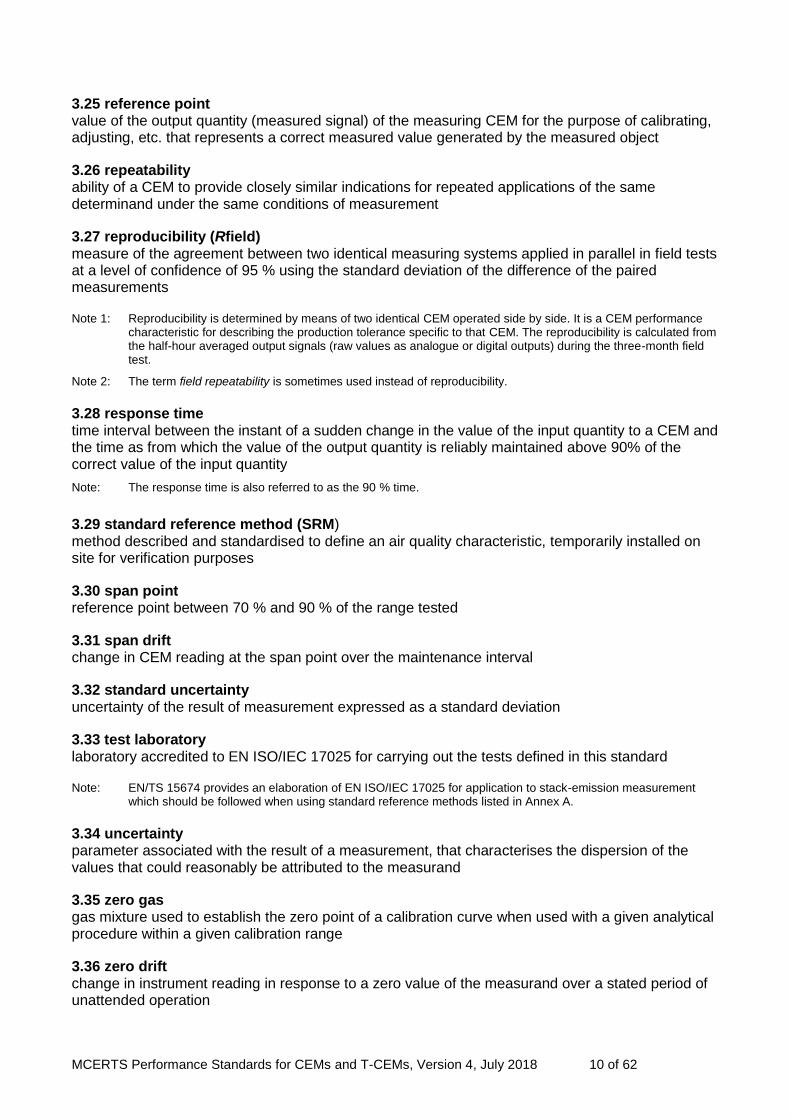
3.25 reference point value of the output quantity (measured signal) of the measuring CEM for the purpose of calibrating, adjusting, etc. that represents a correct measured value generated by the measured object
3.26 repeatability ability of a CEM to provide closely similar indications for repeated applications of the same determinand under the same conditions of measurement
3.27 reproducibility (Rfield) measure of the agreement between two identical measuring systems applied in parallel in field tests at a level of confidence of 95 % using the standard deviation of the difference of the paired measurements
Note 1: Reproducibility is determined by means of two identical CEM operated side by side. It is a CEM performance characteristic for describing the production tolerance specific to that CEM. The reproducibility is calculated from the half-hour averaged output signals (raw values as analogue or digital outputs) during the three-month field test.
Note 2: The term field repeatability is sometimes used instead of reproducibility.
3.28 response time time interval between the instant of a sudden change in the value of the input quantity to a CEM and the time as from which the value of the output quantity is reliably maintained above 90% of the correct value of the input quantity
Note: The response time is also referred to as the 90 % time.
3.29 standard reference method (SRM) method described and standardised to define an air quality characteristic, temporarily installed on site for verification purposes
3.30 span point reference point between 70 % and 90 % of the range tested
3.31 span drift change in CEM reading at the span point over the maintenance interval
3.32 standard uncertainty uncertainty of the result of measurement expressed as a standard deviation
3.33 test laboratory laboratory accredited to EN ISO/IEC 17025 for carrying out the tests defined in this standard
Note: EN/TS 15674 provides an elaboration of EN ISO/IEC 17025 for application to stack-emission measurement which should be followed when using standard reference methods listed in Annex A.
3.34 uncertainty parameter associated with the result of a measurement, that characterises the dispersion of the values that could reasonably be attributed to the measurand
3.35 zero gas gas mixture used to establish the zero point of a calibration curve when used with a given analytical procedure within a given calibration range
3.36 zero drift change in instrument reading in response to a zero value of the measurand over a stated period of unattended operation

MCERTS Performance Standards for CEMs and T-CEMs, Version 4, July 2018 11 of 62
3.37 zero point specified value of the output quantity (measured signal) of the measuring CEM and which, in the absence of the determinand, represents the zero crossing of the CEM characteristic
Note: In case of oxygen and some flow monitoring CEM the zero point is interpreted as the lowest measurable value.
3.38 independent reading reading that is not influenced by a previous individual reading by separating two individual readings by at least four response times
3.39 individual reading reading averaged over a time period equal to the response time of the CEM
MCERTS Performance Standards for CEMs and T-CEMs, Version 4, July 2018 12 of 62
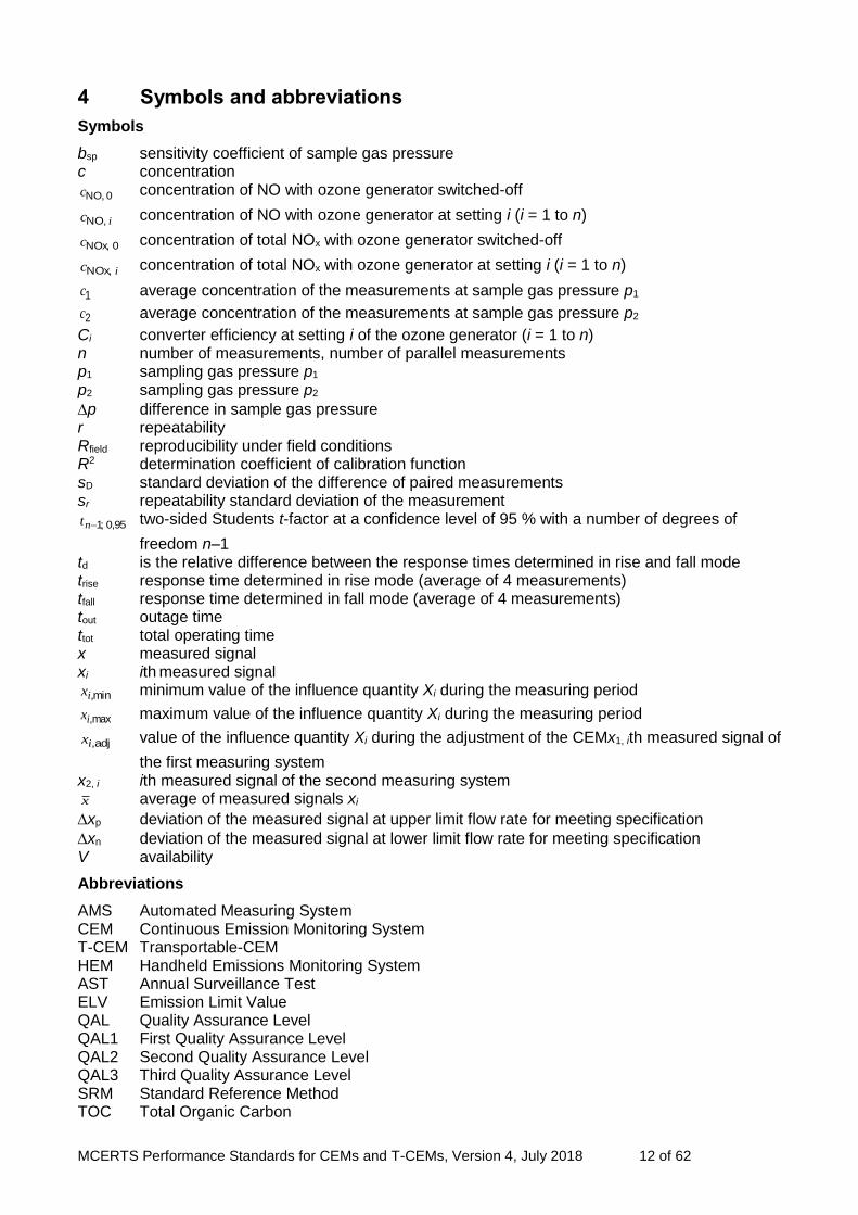
4 Symbols and abbreviations
Symbols
bsp sensitivity coefficient of sample gas pressure c concentration
0NO,c concentration of NO with ozone generator switched-off
icNO, concentration of NO with ozone generator at setting i (i = 1 to n)
0NOx,c concentration of total NOx with ozone generator switched-off
icNOx, concentration of total NOx with ozone generator at setting i (i = 1 to n)
1c average concentration of the measurements at sample gas pressure p1
2c average concentration of the measurements at sample gas pressure p2
Ci converter efficiency at setting i of the ozone generator (i = 1 to n) n number of measurements, number of parallel measurements p1 sampling gas pressure p1 p2 sampling gas pressure p2
p difference in sample gas pressure r repeatability Rfield reproducibility under field conditions R2 determination coefficient of calibration function sD standard deviation of the difference of paired measurements sr repeatability standard deviation of the measurement
95,0;1nt two-sided Students t-factor at a confidence level of 95 % with a number of degrees of
freedom n–1 td is the relative difference between the response times determined in rise and fall mode trise response time determined in rise mode (average of 4 measurements) tfall response time determined in fall mode (average of 4 measurements) tout outage time ttot total operating time x measured signal xi ith measured signal
min,ix minimum value of the influence quantity Xi during the measuring period
max,ix maximum value of the influence quantity Xi during the measuring period
adj,ix value of the influence quantity Xi during the adjustment of the CEMx1, ith measured signal of
the first measuring system x2, i ith measured signal of the second measuring system
x average of measured signals xi
xp deviation of the measured signal at upper limit flow rate for meeting specification
xn deviation of the measured signal at lower limit flow rate for meeting specification V availability
Abbreviations
AMS Automated Measuring System CEM Continuous Emission Monitoring System T-CEM Transportable-CEM HEM Handheld Emissions Monitoring System AST Annual Surveillance Test ELV Emission Limit Value QAL Quality Assurance Level QAL1 First Quality Assurance Level QAL2 Second Quality Assurance Level QAL3 Third Quality Assurance Level SRM Standard Reference Method TOC Total Organic Carbon
MCERTS Performance Standards for CEMs and T-CEMs, Version 4, July 2018 13 of 62
5 General requirements
5.1 Application of performance criteria
The performance criteria defined within this standard shall be applied to two identical CEMs. The CEMs shall also meet the uncertainty requirements specified in the applicable Directives.
5.2 Ranges to be tested
5.2.1 Certification range
The certification range over which the CEM is to be tested shall comprise minimum and maximum values and the coverage shall be fit for the intended application of the CEM. The certification range shall be specified:
for waste incinerators as the range from usually zero, if the CEM is able to measure zero, and a value no greater than 1.5 times the daily average emission limit value (ELV)
for large combustion plants as the range from usually zero, if the CEM is able to measure zero, and a value no greater than 2.5 times the daily average ELV
for other plants in relation to the corresponding ELV or any other requirement related to the intended application
The CEM shall be able to measure instantaneous values in a range that is at least twice the upper limit of the certification range in order to measure the half-hour values. If it is necessary to use more than one range setting of the CEM to achieve this requirement, supplementary ranges require additional testing (see 5.2.2).
Note 1: In addition to the certification ranges stated above, manufacturers can choose supplementary ranges which are larger than the certification range.
Note 2: Manufacturers can choose other ranges for different applications. If a CEM is tested for example on waste incinerators, it can also be used on large combustion plants, if the supplementary ranges are tested as given in 5.2.2.
The certification range(s), and the performance criteria tested for each range shall be stated on the certificate.
Note 3: For a broad industrial application of the certified CEM, the test laboratory should choose for the field test an industrial plant with recognizable difficult boundary conditions. Simpler applications can thus be covered at the same time.
5.2.2 Supplementary ranges
If a manufacturer wishes to demonstrate performance over one or more supplementary ranges larger than the certification range some limited additional testing is required over all the supplementary ranges. This additional testing shall at least include evaluations of the response time (see 10.9) and lack-of-fit (see 10.12). Cross-sensitivity (see 10.19) has to be tested if the interferent concentrations at the industrial plant are higher than those in Table B.1. The supplementary range(s) and the performance criteria tested for these ranges shall be stated on the certificate.
5.2.3 Lower values of ranges
The minimum value of the certification range will usually be zero.
Note 1: The ‘zero’ value is typically the detection limit.
Note 2: For oxygen measuring CEM the minimum value of the certification range may not be zero.
5.2.4 Expression of performance criteria with respect to ranges
The performance criteria presented in Section 8 are generally expressed in terms of a percentage of the maximum of the certification range for each determinand except for oxygen where the performance criteria are expressed as volume concentrations. A performance criterion is a value that corresponds to the largest permitted deviation allowed for each test, regardless of the sign of the deviation determined in the test.
MCERTS Performance Standards for CEMs and T-CEMs, Version 4, July 2018 14 of 62
5.2.5 Ranges of optical in-situ CEMs with variable optical length (cross-stack)
The certification range for optical in-situ CEMs with variable optical length (cross-stack) shall be defined in units of the determinand concentration multiplied by the length of the optical path. The path length used for testing shall be stated on the certificate.
5.3 Manufacturing consistency and changes to CEMs design
Certification of CEMs is specific to the design model which has undergone performance testing. Subsequent design modifications that might affect the performance of the CEMs can invalidate the certification.
Note: Design modifications apply to both hardware and software.
Manufacturing consistency and changes to the design of CEMs are described in EN 15267-2.
5.4 Qualifications of test laboratories
Test laboratories shall be accredited to EN ISO/IEC 17025 and the appropriate test standards for carrying out the tests defined in this standard.
Note: EN/TS 15675 provides an elaboration of EN ISO/IEC 17025 for application to stack-emission measurement which should be followed when using standard reference methods specified at Annex A.

MCERTS Performance Standards for CEMs and T-CEMs, Version 4, July 2018 15 of 62
6 Performance criteria common to all CEMs for laboratory testing
6.1 CEMs for testing
All CEMs submitted for testing shall be complete. These specifications do not apply to the individual parts of a CEM. The certificate shall be issued for a specified CEM with all its parts listed. A CEM which uses extractive sampling systems shall have appropriate provisions to filter solids, avoid chemical reactions within the sampling system, entrainment effects and a means to control the condensation of water. Measuring systems with different options for the sampling line length shall be tested with an appropriate sampling line length agreed between the test laboratory and the manufacturer. The length shall be quoted in the test report.
Note: The use of longer sampling lines is covered by QAL2.
6.2 Requirements of EC Directives – CE labelling
The CEM submitted for testing shall be in conformity with all applicable EC Directives. As of April 2016, these include the Electro-magnetic Compatibility Directive 2014/30/EU (formerly 2004/108/EC), and the Low Voltage Directive 2014/35/EU (formerly 2006/95/EC), covering electrical equipment designed for use within certain voltage limits. Equipment within the scope of the Hazardous Atmospheres Directive, 2014/34/EU (formerly 94/9/EC) falls outside the scope of this MCERTS document. CEM manufacturers or suppliers shall supply declarations of conformity to all relevant Directives applicable to the equipment.
6.3 Security
The CEM shall have a means of protection against unauthorised access to control functions.
6.4 Output ranges and zero-point
The CEM shall have a data output with a living zero point (for example 4 mA) such that both negative and positive readings can be displayed. The CEM shall have a display that shows the measurement response. The display may be external to the CEM.
6.5 Additional data outputs
The CEM shall have a data output allowing an additional data display and recording device to be fitted to the CEM.
6.6 Display of operational status signals
The CEM shall have a means of displaying its operating status.
Note: Status signals cover, for example, normal operation, stand-by, maintenance mode, malfunctions.
The CEM shall also have a means of communicating the operational status to a remote system.
6.7 Prevention or compensation for optical contamination
A CEM that uses an optical method as the measuring principle shall have provisions for either prevention of contamination of the optical system and/or compensation for its effects.
6.8 Degrees of protection provided by enclosures
Instruments kept within ventilated rooms or cabinets, where any kind of precipitation cannot reach the instrument, shall meet at least IP40 specified in EN 60529. Instruments limited to be mounted in areas, where some kind of shelter against precipitation is in place, for example a porch roof, but precipitation may reach the instrument due to wind, shall meet at least IP54 specified in EN 60529.

MCERTS Performance Standards for CEMs and T-CEMs, Version 4, July 2018 16 of 62
CEMs which are designed to be used in the open air and without any weather protection shall at least meet the requirements of standard IP65 specified in EN 60529.
6.9 Response time
The CEM shall meet the performance criteria for response time specified in Section 8.
6.10 Repeatability standard deviation at zero point
The CEM shall meet the performance criteria for repeatability standard deviation at the zero point specified in Section 8. The detection limit is two times the repeatability standard deviation at zero.
Note: Quantification limit is four times the repeatability standard deviation at zero.
6.11 Repeatability standard deviation at the span point
The CEM shall meet the performance criteria for repeatability standard deviation at the span point specified in Section 8.
6.12 Lack-of-fit
The CEM shall have a linear response and shall meet the performance criteria for lack-of-fit specified in Section 8.
6.13 Zero and span drift
The manufacturer shall provide a description of the technique used by the CEM to determine and compensate the zero and span drift. The description shall not be limited to an explanation of how the CEM compensates for the effect of contamination of the optical surfaces of a CEM which use optical techniques. The test laboratory shall assess that the chosen reference material applied to the CEM as an independent check of the instrument’s operation is capable of monitoring any credible change in instrument response not caused by changes in the measured component or stack condition. The CEM shall allow recording of the zero and span drift. The manufacturer shall describe how to obtain the zero and span values.
Note 1: The technique should be sensitive to drift in as many of the active parts of the system as possible.
If the CEM has a means of automatic compensation for contamination and calibration and re-adjustment for zero and span drift, and such adjustments are not capable of bringing the CEM within normal operational conditions, then the CEM shall set a status signal. In cases where the CEM cannot measure zero values, the drift has to be measured at the lower limit of the certification range.
Note 2: For example, some CEM which measure flow and oxygen are not able to measure true zero values.
6.14 Influence of ambient temperature
The deviations of the CEM readings at the zero and span points shall not exceed the performance criteria specified in Section 8 when the ambient temperature varies from –20 °C to +50 °C, unless assemblies are installed indoors where the temperatures do not fall below +5 °C or rise above +40 °C, in which case the test range shall be +5 °C to +40 °C. The manufacturer submitting a CEM for testing may specify wider ambient temperature ranges to those above.
Note: Temperature ranges tested are indicated in the certificate.
6.15 Influence of sample gas pressure
The deviation of the CEM reading at the span point shall not exceed the performance criterion specified in Section 8 when the sample gas pressure changes by 3 kPa above or below
MCERTS Performance Standards for CEMs and T-CEMs, Version 4, July 2018 17 of 62
atmospheric pressure.
Note: This typically applies to in-situ CEMs, but not to extractive CEMs, since the sample gas is conditioned and typically not subject to significant variations of temperature and pressure once within the analyser.
6.16 Influence of sample gas flow for extractive CEMs
The deviation of the CEM reading at the span point shall not exceed the performance criterion specified in Section 8, when the sample gas flow is changed in accordance with the manufacturer's specification. A status signal for the lower limit of the sample gas flow shall be provided.
6.17 Influence of voltage variations
The deviation of the CEM reading at the zero and span points shall not exceed the performance criterion specified in Section 8 when the voltage supply to the CEM varies from –15 % to +10 % from the nominal value of the supply. CEMs shall be capable of operating at a voltage which meets the requirements of BS EN 50160.
6.18 Influence of vibration
The CEM shall be unaffected by the levels of vibration typically expected during installation at an industrial plant. The influence of vibration is acceptable if the deviations of the CEM readings at the zero and span points do not exceed the performance criteria specified in Section 8.
6.19 Cross-sensitivity
The manufacturer shall describe any known sources of interference. Tests for non-gaseous interference sources, or gases other than those listed in Annex B, shall be agreed with the test laboratory. The CEM shall meet the performance criteria at the zero and span point for cross-sensitivity specified in Section 8.
6.20 Excursion of measurement beam of cross-stack in-situ CEMs
In the event of an excursion of the measurement beam within a CEM, the deviation of the CEM reading shall not exceed the performance criterion specified in Section 8 for the maximum allowable deviation angle specified by the manufacturer. This shall not be smaller than 0.3°.
6.21 Converter efficiency for NOx-monitoring CEMs
Manufacturers shall specify, when seeking certification of CEMs for measuring NOx, whether certification is required for the measurement of nitrogen monoxide (NO) and/or nitrogen dioxide (NO2). If a converter is used, the converter shall meet the performance criteria for the converter efficiency specified in Section 8.
Note 1: NOx ordinarily means nitrogen monoxide (NO) plus nitrogen dioxide (NO2).
Note 2: NOx concentrations are generally expressed as NO2.
6.22 Response factors
CEMs for TOC shall meet the performance criteria specified in Section 8.
MCERTS Performance Standards for CEMs and T-CEMs, Version 4, July 2018 18 of 62
7 Performance criteria common to all CEMs for field testing
7.1 Calibration function
The variability attached to the calibration function and determined in accordance with EN 14181 shall meet the maximum permissible uncertainty specified by the applicable regulations. The calibration function shall have a determination coefficient of the regression of at least R2= 0.9. The calibration function shall be determined by parallel measurements carried out using a SRM.
Note 1: If the concentration in the field does not vary, the calibration function can be established in accordance with EN 14181 by additional use of zero and span values obtained in the field test.
Note 2: The determination coefficient R2 is the square of the regression coefficient R.
Note 3: The case of quadratic calibration functions is described in EN 13284-2.
7.2 Response time
The response time shall meet the same performance criterion evaluated during the laboratory tests.
Note: The test for the response time is repeated during the field test, as field conditions can influence the response time.
7.3 Lack-of-fit
The lack-of-fit shall meet the same performance criterion evaluated during the laboratory tests.
Note 1: The test for the lack-of-fit is repeated during the field test, as field conditions can influence the lack-of-fit.
Note 2: There is no lack-of-fit requirement for Class 2 and Class 3 particulate monitors.
7.4 Maintenance interval
The minimum maintenance interval of the CEM shall meet the performance criterion specified in Section 8.
7.5 Zero and span drift
The zero and span drift within the maintenance interval shall not exceed the performance criteria specified in Section 8. When selecting span materials (such as gases) during testing, the level of these materials shall be between 70 % and 90 % of the upper limit of the certification range.
Note: As field conditions can influence drift behaviour, tests for this characteristic are repeated during the field test.
7.6 Availability
The CEM shall have an availability which meets the requirements of applicable regulations and in any case, the performance criterion specified in Section 8 during the field test.
Note: If the CEM is not measuring the measured component for any reason, then it is not considered as being available for measurements. The CEM can be unavailable due to malfunctions, servicing and any kind of zero and span point evaluation and correction. Periods when the monitored process is not operating are excluded.
7.7 Reproducibility
The CEM shall meet the performance criterion for reproducibility under field conditions specified in Section 8.
7.8 Contamination check of in-situ systems
The response of the CEM to contamination of the optical components shall be determined in the field test by means of visual checks and, for example, by determining deviation from the rated values of the performance characteristic for the CEM. If required, the CEM shall be provided with recommended air purging systems for three months as part of the field test. At the end of the test, the effect of contamination shall be evaluated. The results with clean and contaminated optical surfaces shall differ by no more than 2 % of the upper limit of
MCERTS Performance Standards for CEMs and T-CEMs, Version 4, July 2018 19 of 62
the certification range.
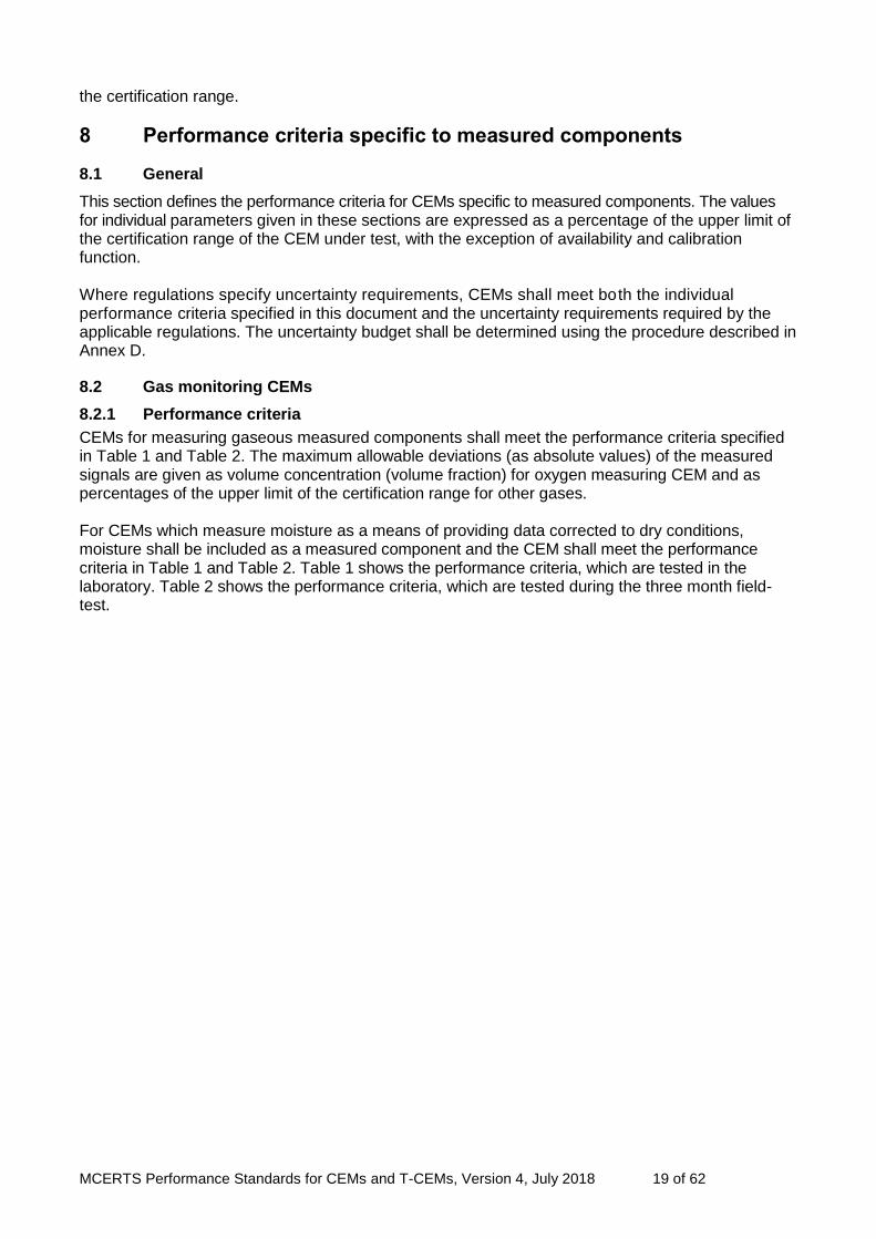
8 Performance criteria specific to measured components
8.1 General
This section defines the performance criteria for CEMs specific to measured components. The values for individual parameters given in these sections are expressed as a percentage of the upper limit of the certification range of the CEM under test, with the exception of availability and calibration function. Where regulations specify uncertainty requirements, CEMs shall meet both the individual performance criteria specified in this document and the uncertainty requirements required by the applicable regulations. The uncertainty budget shall be determined using the procedure described in Annex D.
8.2 Gas monitoring CEMs
8.2.1 Performance criteria
CEMs for measuring gaseous measured components shall meet the performance criteria specified in Table 1 and Table 2. The maximum allowable deviations (as absolute values) of the measured signals are given as volume concentration (volume fraction) for oxygen measuring CEM and as percentages of the upper limit of the certification range for other gases. For CEMs which measure moisture as a means of providing data corrected to dry conditions, moisture shall be included as a measured component and the CEM shall meet the performance criteria in Table 1 and Table 2. Table 1 shows the performance criteria, which are tested in the laboratory. Table 2 shows the performance criteria, which are tested during the three month field-test.

MCERTS Performance Standards for CEMs and T-CEMs, Version 4, July 2018 20 of 62
Table 1 - Performance criteria for gas monitoring CEMs in laboratory tests
Performance characteristic Performance Criteria Test in
clause Gases
except O2
O2B
Response time < 200 s
(< 400 s for NH3, HCl and HF)
< 200 s 10.9
Repeatability standard deviation at zero point < 2.0 % A < 0.20 % B 10.10
Repeatability standard deviation at span point < 2.0 % A < 0.20 % B 10.11
Lack-of-fit (linearity) < 2.0 % A < 0.20 % B 10.12
Influence of ambient temperature change from 20 °C
within specified range at zero point < 5.0 % A < 0.50 % B 10.14
Influence of ambient temperature change from 20 °C
within specified range at span point < 5.0 % A < 0.50 % B 10.14
Influence of sample gas pressure at span point, for a pressure change Ap of 3 kPa
< 2.0 % A < 0.20 % B 10.15
Influence of sample gas flow on extractive CEM for a
given specification by the manufacturer < 2.0 % A < 0.20 % B 10.16
Influence of voltage, at –15 % and at +10 % from
nominal supply voltage < 2.0 % A < 0.20 % B 10.17
Influence of vibration < 2.0 % A < 0.20 % B 10.18
Cross-sensitivity < 4.0 % A < 0.40 % B 10.19
Excursion of the measurement beam of cross-stack
in-situ CEM < 2.0 % A – 10.20
Converter efficiency for CEM measuring NOx ≥ 95.0 % – 10.21
A Percentage value as percentage of the upper limit of the certification range.
B Percentage value as oxygen volume concentration (volume fraction).

MCERTS Performance Standards for CEMs and T-CEMs, Version 4, July 2018 21 of 62
Table 2 — Performance criteria for gas monitoring CEMs in field tests
Performance characteristic Performance criteria Test in clause
Gases except O2
O2
Determination coefficient of calibration function, R2
0.90 0.90 12.1
Availability 95.0 % 98,0 % 12.6
Lack-of-fit 2.0 % A 0.20 % B 12.3
Zero drift, within maintenance interval 3.0 % A 0.20 % B 12.5
Span drift, within maintenance interval 3.0 % A 0.20 % B 12.5
Reproducibility, Rfield 3.3 % A 0.20 % B 12.7
Minimum maintenance interval 8 days 8 days 12.4
Response time
<200s
(<400s for HCl, HF and NH3)
<200s 12.2
A Percentage values as percentages of the upper limit of the certification range. B Percentage values as oxygen volume concentration (volume fraction).
Note: The availability during operation is specified, for example in applicable EC Directives.
8.2.2 CEMs for total organic carbon
CEMs for measuring total organic carbon shall meet the performance criteria specified in Table 1 and Table 2. Furthermore, the performance criteria for the effect of oxygen and the response factors specified in Table 3 shall be applied in 10.22.
Table 3 — Performance criteria for CEMs measuring Total Organic Carbon (TOC) in laboratory tests
Performance characteristic Performance criteria
Effect of oxygen ≤ 2 % A
Range of response factors:
methane 0.9 to 1.2
aliphatic hydrocarbons 0.90 to 1.10
aromatic hydrocarbons 0.8 to 1.1
dichloromethane 0.75 to 1.15
aliphatic alcohols 0.7 to 1.0
esters and ketones 0.7 to 1.0
organic acids 0.5 to 1.0
A: Percentage value as percentage of the upper limit of the certification range.
Note 1: EN 12619 specifies performance criteria including response factors for TOC analysers which use flame ionisation detection (FID), particularly when the FID is used as a SRM. However, the performance criteria in this document apply to any techniques which can be used to measure TOC or a surrogate for TOC (for example, other techniques, such as Fourier Transform Infrared (FTIR) can be used to measure TOC if CEMs using other techniques meet the required performance criteria).
Note 2: TOC is measured as volatile organic carbon, as defined in EN 12619.

MCERTS Performance Standards for CEMs and T-CEMs, Version 4, July 2018 22 of 62
8.3 CEMs for monitoring particulate matter
CEMs for measuring particulate matter shall meet the performance criteria detailed in Table 4 and Table 5. The maximum allowable deviations (as absolute values) of the measured signals are given as percentages of the upper limit of the certification range. Table 4 details the performance criteria, which are tested in the laboratory. Table 5 details the performance criteria, which are tested during
the three month field-test.
Table 4 — Performance criteria for particulate-monitoring CEMs in the laboratory tests
Performance characteristic Performance
criteria
Test in
clause
Response time < 200 s 10.9
Repeatability standard deviation at zero < 2.0 % A 10.10
Repeatability standard deviation at span < 5.0 % A 10.11
Lack-of-fit (linearity) < 3.0 % A 10.12
Zero shift due to ambient temperature change from 20 °C within specified range
< 5.0 % A 10.14
Span shift due to ambient temperature change from 20 °C within specified range
< 5.0% A 10.14
Influence of voltage at +15 % and at –10 % from nominal supply voltage < 2.0 % A 10.17
A Percentage value as percentage of the upper limit of the certification range.
Note 1: The response time does not apply to batch-measurement techniques such as beta-ray-attenuation.
Note 2: There are additional wind-tunnel tests for Class 2 and 3 particulate monitors. The test laboratory shall include the results of these tests in the test report.
MCERTS Performance Standards for CEMs and T-CEMs, Version 4, July 2018 23 of 62
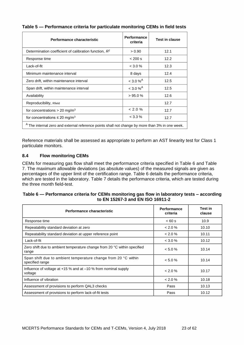
Table 5 — Performance criteria for particulate monitoring CEMs in field tests
Performance characteristic Performance
criteria Test in clause
Determination coefficient of calibration function, R2 > 0.90 12.1
Response time < 200 s 12.2
Lack-of-fit < 3.0 % 12.3
Minimum maintenance interval 8 days 12.4
Zero drift, within maintenance interval < 3.0 %A 12.5
Span drift, within maintenance interval < 3.0 %A 12.5
Availability > 95.0 % 12.6
Reproducibility, Rfield 12.7
for concentrations > 20 mg/m3 < 2.0 % 12.7
for concentrations ≤ 20 mg/m3 < 3.3 % 12.7
A The internal zero and external reference points shall not change by more than 3% in one week.
Reference materials shall be assessed as appropriate to perform an AST linearity test for Class 1 particulate monitors.
8.4 Flow monitoring CEMs
CEMs for measuring gas flow shall meet the performance criteria specified in Table 6 and Table 7. The maximum allowable deviations (as absolute values) of the measured signals are given as percentages of the upper limit of the certification range. Table 6 details the performance criteria, which are tested in the laboratory. Table 7 details the performance criteria, which are tested during the three month field-test.
Table 6 — Performance criteria for CEMs monitoring gas flow in laboratory tests – according to EN 15267-3 and EN ISO 16911-2
Performance characteristic Performance
criteria
Test in
clause
Response time < 60 s 10.9
Repeatability standard deviation at zero < 2.0 % 10.10
Repeatability standard deviation at upper reference point < 2.0 % 10.11
Lack-of-fit < 3.0 % 10.12
Zero shift due to ambient temperature change from 20 °C within specified range
< 5.0 % 10.14
Span shift due to ambient temperature change from 20 °C within specified range
< 5.0 % 10.14
Influence of voltage at +15 % and at –10 % from nominal supply voltage
< 2.0 % 10.17
Influence of vibration < 2.0 % 10.18
Assessment of provisions to perform QAL3 checks Pass 10.13
Assessment of provisions to perform lack-of-fit tests Pass 10.12
MCERTS Performance Standards for CEMs and T-CEMs, Version 4, July 2018 24 of 62
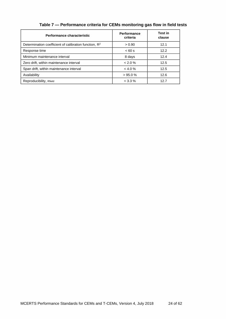
Table 7 — Performance criteria for CEMs monitoring gas flow in field tests
Performance characteristic Performance
criteria
Test in
clause
Determination coefficient of calibration function, R2 > 0.90 12.1
Response time < 60 s 12.2
Minimum maintenance interval 8 days 12.4
Zero drift, within maintenance interval < 2.0 % 12.5
Span drift, within maintenance interval < 4.0 % 12.5
Availability > 95.0 % 12.6
Reproducibility, Rfield < 3.3 % 12.7

MCERTS Performance Standards for CEMs and T-CEMs, Version 4, July 2018 25 of 62
9 General test requirements
The test laboratory shall perform all relevant tests on two identical CEMs. These two CEMs have to be tested in the laboratory and field. Multiple-component CEMs shall meet the performance criteria on each individual measured component with all measurement channels operating simultaneously.
Note 1: The test is performed in such a way that the material under analysis (the measured component) is admitted to all measurement channels in the laboratory test and in the field test.
Changes in the environmental and test conditions shall not have a significant influence on the performance characteristic tested. Therefore, all environmental and test conditions which have an influence on the CEM shall be kept stable as far as practicable. The environmental and test conditions shall be recorded during the test. All test results shall be reported at standard conditions (0 °C, 101.3 kPa, dry gas). The test laboratory shall evaluate the performance of the CEMs at the lowest certification range possible for the intended application chosen by the manufacturer. If the CEM is to be used for industrial plants requiring assurance over higher measurement ranges, then the test laboratory shall perform selected additional tests to demonstrate satisfactory performance over higher ranges. These additional tests shall at least include evaluations of the response time and lack-of-fit. Cross-sensitivity (see 10.19) has to be tested if the interferent concentrations at the industrial plant are higher than those in Table B.1.
Note 2: Certification range is selected by the manufacturer in consultation with the test laboratory.
The test requirements specified in clauses 10 to 13 are the minimum requirements. The tests are divided into two sections, covering general test requirements for all CEMs, followed by measured component specific test requirements. These shall include:
a description of the test method
the evaluation procedure
assessment of performance against the relevant performance criterion
where appropriate, information on any specialised test equipment If a test requires two or more test cycles and the CEM meets the performance criterion by a factor of two or more for the first test then any subsequent testing for this performance characteristic may be omitted. If a test requires several readings, the average of these readings shall be determined. If a test has to be repeated (several test cycles), the averages of the individual test cycles shall be determined and shall meet the applicable performance criteria. The expanded uncertainty of the concentration of test gases at a level of confidence of 95 % shall not exceed 3 %. For the lack-of-fit test, the bench shall provide gases, the concentration of which shall not have an expanded uncertainty of greater than 33 % of the lack-of-fit criterion. Tests do not have to be performed in the numerical order in this document, as the selection of tests and their order depend on the characteristics and type of individual CEM. However, the first two laboratory tests using test gases are the response time test followed by the lack-of-fit test.
Note 3: The field test is usually carried out after all laboratory tests are passed.
Note 4: A short-term drift test performed after the response time test can show that drift is not influencing the results of the other tests. As a guideline, a short-term drift test could be 24 hours long, where a drift at zero and span point of more than 2 % of the upper limit of the certification range indicates that the CEM will not be sufficiently stable for the remainder of the tests.
The test laboratory shall document whether the CEM meets all of the relevant performance criteria, and shall record all environmental conditions pertaining during testing.

MCERTS Performance Standards for CEMs and T-CEMs, Version 4, July 2018 26 of 62
10 Test procedures for laboratory tests
10.1 CEM for testing
The test laboratory shall check whether the CEMs are complete and identical, by examining the appropriate parts, as specified in the manufacturer’s documentation. The test laboratory shall check that extractive CEMs have appropriate provisions for filtering solids, avoiding chemical reactions within the sampling system, entrainment effects and effective control of water condensate. The test laboratory shall include diagrams and photographs of both CEMs, in the test report, and copies of the operating manual(s) for the CEMs.
Note 1: In addition to the analyser, a CEM can include the sampling probe, the sampling hose, the test-gas conditioning-facility, any special test components and the operating instructions.
The hardware used shall be photographed and the software version both established and recorded in the test report. Changes in the CEM configuration are not permitted during testing.
Note 2: Minor repairs needed to perform the test but without influence on the instrument performance can be carried out, and the test be continued.
10.2 CE labelling
If the CEM needs to comply with the requirements for CE labelling as specified in applicable EC Directives, then the test laboratory shall verify whether there is traceable evidence of compliance.
10.3 Security
The CEM shall be set up according to the operating instructions. The test laboratory shall then activate the security mechanisms provided by the CEM manufacturer to prevent inadvertent and unauthorised maladjustment. A check shall then be carried out to establish whether the security mechanisms operate effectively.
Note 1: Adjustment can include zero and span adjustments, deletion of data sets, changing averaging times and altering ranges.
Note 2: Security mechanisms can include a key or security codes programmed into the CEM which are keyed into the CEM before adjustments are permitted.
10.4 Output ranges and zero point
The test laboratory shall check whether the ranges on the CEM can be adjusted and whether such ranges are appropriate for the intended applications.
Note: The ELVs to be monitored with this CEM should be documented, together with an indication of the suitability of the CEM ranges for (i) applicable Chapters of the IED and (ii) other intended applications.
Using reference materials, and by adjusting the zero point on the CEM, the test laboratory shall check that the indicated zero point on the measurement display and output of the CEM is a true “living” zero, and that the CEM can display both positive and negative readings. The test laboratory shall use reference materials to verify that the output range is at least twice as great as the certification range.
10.5 Additional data outputs
The test laboratory shall check that the CEM is equipped with an additional data output which allows for example a recording system or computer to be connected. The test laboratory shall check that measurement signals displayed on the additional data output are the same results as those on the CEM. The test laboratory shall assess and describe in the test report the mechanism of the additional data output.

MCERTS Performance Standards for CEMs and T-CEMs, Version 4, July 2018 27 of 62
10.6 Display of operational status signals
The test laboratory shall assess whether the CEM has a means of displaying and providing data for recording the relevant operational status (for example standby, service, malfunction). The test laboratory shall then assess whether each operating mode is correctly identified and outputted by the CEM.
10.7 Prevention or compensation for optical contamination
For optical techniques, the test laboratory shall assess whether contamination of the optical boundary surfaces interferes with the measuring technique. If contamination interferes with the measuring technique, the effect of contamination on the performance of an optical instrument shall be determined by inserting an optical filter on the process side of the optical surfaces and monitoring the change in signal caused by such contamination. The test should be repeated for both the transmitter and receiver optics and should be performed with an optical filter between 4 % and 10 % nominal opacity. If contamination compensation functions are available on the instruments these should be activated during the tests. For instruments with in-built contamination compensation, the absorption of the optical filter may be specified by the manufacturer to be larger than 10 % in order for the compensation capability of the instrument to be more fully tested. The influence of optical boundary surface soiling on the measurement signal shall be determined while taking into account the physical relationships, and quantified wherever possible through measurements. There are many types of optical techniques and it is difficult to specify in detail the exact procedures for conducting this test. Therefore the test laboratory should have procedures and adjusting aids, (for example reference filter, homogeneous and inhomogeneous particulate coatings) for assessing the effect of soiling on different types of optical system, and then record the types of tests employed in the test report. The process employed inside the CEM for monitoring the effect of contamination shall be described by the CEM manufacturer. This function shall be operable with the CEM installed and operational. The CEM shall also display when the function is working. The test report shall contain a description of the CEM-specific method for monitoring soiling. Test results shall be presented in tabular form. The minimum and maximum deviation from rated value shall be documented. The intervals for cleaning the optical boundary surfaces shall be specified for the operating conditions encountered in the performance test.
10.8 Degrees of protection provided by enclosures
The effect of liquid water on the CEM shall be assessed by inspection in relation to EN 60529. The CEM manufacturer shall provide the test laboratory with the report of testing of the enclosure according to EN 60529. The test laboratory shall assess this test report to ensure compliance with the requirements of 6.8.
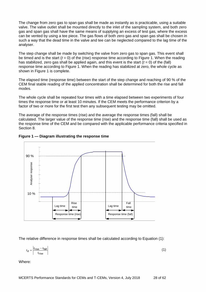
10.9 Response time
The test laboratory shall determine the CEM response time using zero and span reference materials (see Figure 1). The zero and span reference materials shall be stable test gases when determining the response time of the gas-measuring CEM. The test shall be performed with dry and wet test gases.
Note 1: The zero and span material can include surrogates, such as filters.
Note 2: This test provides the initial stabilisation period, which is then used in other tests described in this document.
Note 3: This test can also be combined with the lack-of-fit test, using the highest concentration in the lack-of-fit test to determine the response time.
Note 4: The response time test is also repeated in the field as real waste gas conditions can influence response times.
MCERTS Performance Standards for CEMs and T-CEMs, Version 4, July 2018 28 of 62
The change from zero gas to span gas shall be made as instantly as is practicable, using a suitable valve. The valve outlet shall be mounted directly to the inlet of the sampling system, and both zero gas and span gas shall have the same means of supplying an excess of test gas, where the excess can be vented by using a tee piece. The gas flows of both zero gas and span gas shall be chosen in such a way that the dead time in the valve and tee can be neglected compared to the lag time of the analyser. The step change shall be made by switching the valve from zero gas to span gas. This event shall be timed and is the start (t = 0) of the (rise) response time according to Figure 1. When the reading has stabilized, zero gas shall be applied again, and this event is the start (t = 0) of the (fall) response time according to Figure 1. When the reading has stabilized at zero, the whole cycle as shown in Figure 1 is complete. The elapsed time (response time) between the start of the step change and reaching of 90 % of the CEM final stable reading of the applied concentration shall be determined for both the rise and fall modes. The whole cycle shall be repeated four times with a time elapsed between two experiments of four times the response time or at least 10 minutes. If the CEM meets the performance criterion by a factor of two or more for the first test then any subsequent testing may be omitted. The average of the response times (rise) and the average the response times (fall) shall be calculated. The larger value of the response time (rise) and the response time (fall) shall be used as the response time of the CEM and be compared with the applicable performance criteria specified in Section 8.
Figure 1 — Diagram illustrating the response time
The relative difference in response times shall be calculated according to Equation (1):
rise
fallrised
t
ttt
(1)
Where:
10 %
90 %
Lag time Rise time
Response time (rise) Response time (fall)
Lag time Fall time
Analy
ser
response
MCERTS Performance Standards for CEMs and T-CEMs, Version 4, July 2018 29 of 62
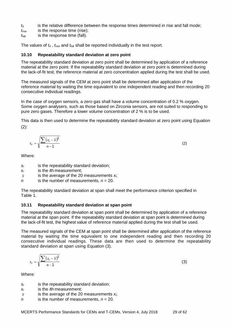
td is the relative difference between the response times determined in rise and fall mode; trise is the response time (rise); tfall is the response time (fall). The values of td , trise and tfall shall be reported individually in the test report.
10.10 Repeatability standard deviation at zero point
The repeatability standard deviation at zero point shall be determined by application of a reference material at the zero point. If the repeatability standard deviation at zero point is determined during the lack-of-fit test, the reference material at zero concentration applied during the test shall be used. The measured signals of the CEM at zero point shall be determined after application of the reference material by waiting the time equivalent to one independent reading and then recording 20 consecutive individual readings. In the case of oxygen sensors, a zero gas shall have a volume concentration of 0.2 % oxygen. Some oxygen analysers, such as those based on Zirconia sensors, are not suited to responding to pure zero gases. Therefore a lower volume concentration of 2 % is to be used.
This data is then used to determine the repeatability standard deviation at zero point using Equation
(2):
1
2
n
xxs
ir (2)
Where: sr is the repeatability standard deviation; xi is the ith measurement;
x is the average of the 20 measurements xi;
n is the number of measurements, n = 20. The repeatability standard deviation at span shall meet the performance criterion specified in Table 1.
10.11 Repeatability standard deviation at span point
The repeatability standard deviation at span point shall be determined by application of a reference material at the span point. If the repeatability standard deviation at span point is determined during the lack-of-fit test, the highest value of reference material applied during the test shall be used.
The measured signals of the CEM at span point shall be determined after application of the reference material by waiting the time equivalent to one independent reading and then recording 20 consecutive individual readings. These data are then used to determine the repeatability standard deviation at span using Equation (3).
1
2
n
xxs
ir (3)
Where: sr is the repeatability standard deviation; xi is the ith measurement;
x is the average of the 20 measurements xi;
n is the number of measurements, n = 20.

MCERTS Performance Standards for CEMs and T-CEMs, Version 4, July 2018 30 of 62
The repeatability standard deviation at span shall meet the performance criterion specified in Table 1.
10.12 Lack-of-fit
The test laboratory shall perform the lack-of-fit test according to Annex C. The linearity of the response of the CEM shall be checked using at least seven different reference materials, including a zero concentration. This test requires:
a gas mixing system compliant with national standards and with a maximum expanded uncertainty of 33 % of the lack-of-fit criterion
test standards (for example zero gas, test gas of suitable concentration, reference materials)
a data recording system The reference material with zero concentration, as well as the reference materials shall have a verifiable quantity and quality. Gaseous reference materials can be obtained from different gas cylinders or can be prepared by means of a calibrated dilution system from one single gas concentration. The test gas concentrations shall be selected such that the measured values are equally spaced over the certification range. It is necessary to know the values of the ratios of their concentrations precisely enough so that an incorrect failure of the lack-of-fit test does not occur. The dry or wet test gases shall be applied to the inlet of the CEM. The reference materials shall be applied in an order, which avoids hysteresis effects. For the application of seven reference materials, avoidance of hysteresis effects can be achieved, for example, by the following sequence:
reference material with zero concentration
reference material concentration approximately 70 % of the upper limit of the certification range
reference material concentration approximately 40 % of the upper limit of the certification range
reference material with zero concentration
reference material concentration approximately 60 % of the upper limit of the certification range
reference material concentration approximately 10 % of the upper limit of the certification range
reference material concentration approximately 30 % of the upper limit of the certification range
reference material concentration approximately 90 % of the upper limit of the certification range
reference material with zero concentration After each change in concentration, the measured signals of the CEM shall be determined by waiting the time equivalent to one independent reading and then recording three consecutive individual readings. The three individual readings shall be averaged. The test shall be repeated three times. If the CEM meets the performance criterion by a factor of two or more for the first test then any subsequent testing may be omitted.
Note 1: This procedure means that the quality of the reference material can influence the result of the tests. It should be noted, however, that it is the result that leads to a pass or failure in the test. In some cases, a reference material with a higher quality can change the result from fail to pass.
Note 2: Special care should be taken, when handling NH3, HCl or HF in dry gases. For example, particular surface reactions in tubing can result in a very long response time, which is not representative of the response time for humid gases.
Note 3: Where no other method is practicable, the linearity test can also be performed with the aid of reference materials, such as grating filters or gas filters.

MCERTS Performance Standards for CEMs and T-CEMs, Version 4, July 2018 31 of 62
Note 4: The reference material at zero concentration applied during the lack-of-fit test can also be used to determine the repeatability standard deviation at zero point (see 10.10).
Note 5: The highest value of reference material applied during the lack-of-fit test can also be used to determine the repeatability standard deviation at span point (see 10.11).
Note 6: This test is performed in the same way for supplementary ranges (see 5.2.2).
The lack-of-fit shall be evaluated according to Annex C. In this test procedure, a regression line is established between the instrument readings of the CEM (x values) and the reference material values (c values). In the next step, the average of CEM readings at each level is calculated. Then the deviation (residual) of this average to the regression line is calculated. The relative residuals dc,rel shall meet the applicable performance criteria specified in Section 8 for all reference materials applied. Test records, raw data and results of CEM characteristics shall be documented. The individual values shall be presented together with a statement of the test period for each CEM. The test set-up and ambient conditions shall also be documented.
10.13 Zero and span drift
The aim of this test is to determine that the CEM allows the recording of zero and span drift to satisfy the QAL3 requirements according to EN 14181.
Note: A short-term drift test performed after the response time test can show that drift is not influencing the results of the other tests. As a guideline, a short-term drift test could be 24 hours long, where a drift at zero and span point of more than 2 % of the upper limit of the certification range indicates that the CEM will not be sufficiently stable for the remainder of the tests. Zero and span point drift are checked individually. Span point drift is not corrected for zero point drift.
If the CEM has an automatic mechanism for correcting drift, then the test laboratory shall verify its effectiveness by simulating drift by a procedure agreed between the manufacturer and test laboratory. Following any automatic corrections, the test laboratory shall check the zero point and span points using reference materials, and verify the accuracy of these readings. The test laboratory shall check that the CEM indicates a fault and/or a need for maintenance, if the automatic adjustment is not capable of bringing the CEM within normal operational conditions. In the test report, the test laboratory shall describe any mechanisms for automatic corrections of drift, the data recorded during the simulated drift checks and the maintenance interval. If the QAL3 procedure described in EN 14181 is incorporated within the CEM, this procedure shall be assessed by the test laboratory.
10.14 Influence of ambient temperature
The test laboratory shall determine how the zero and span values of the CEM are influenced by changes in ambient temperature by using a climatic chamber which can control ambient temperature from –20°C to +50°C, within limits of ±1.0 K. In the case of CEM installed outdoors, the following temperatures shall be set in the climatic chamber in the given order of sequence: 20 °C → 0 °C → –20 °C → 20 °C → 50 °C → 20 °C. In the case of CEM installed at temperature-controlled locations, the following temperatures shall be set in the given order of sequence: 20 °C → 5 °C → 20 ° C → 40 °C → 20 °C. After a sufficient equilibration period, the measured signals of the CEM at zero point and at span point shall be determined at each temperature by waiting the time equivalent to one independent reading and then recording three consecutive individual readings. The three individual readings shall be

MCERTS Performance Standards for CEMs and T-CEMs, Version 4, July 2018 32 of 62
averaged. The test laboratory shall wait at least six hours between each temperature change in the environmental chamber, to allow the CEM to equilibrate, before taking further readings. Once the test laboratory has completed one cycle, the test shall be repeated over two more temperature cycles. Alternatively, the test laboratory may monitor the reading from the CEM following each temperature change. If the instrument stabilises in less than six hours, then the test laboratory may reduce the equilibration period. However, the test laboratory shall record objective and verifiable evidence to support this. The CEM shall remain switched on when varying the ambient temperature in the environmental chamber. The deviations between the average reading at each temperature and the average reading at 20°C shall be determined. The deviations shall meet the applicable performance criteria specified in Section 8 for all temperatures. The test shall be repeated three times at the zero point and three times at the span point. If the CEM meets the performance criterion by a factor of two or more for the first test then any subsequent testing may be omitted. The individual readings, averages and deviations at each temperature as well as the maximum deviation at zero point and at span point shall be reported. In addition, the test laboratory shall determine and report the maximum sensitivity coefficient for the temperature dependence. The sensitivity coefficients at each temperature shall be calculated by Equation (4):
1
1-t
nn
nn
TT
ccb (4)
Where:
bt is the ambient temperature dependence; cn is the average concentration of the measurements at temperature Tn; cn–1 is the average concentration of the measurements at temperature Tn–1; Tn is the current temperature in the test cycle; Tn–1 is the previous temperature in the test cycle. The test laboratory shall document the minimum and maximum deviations from the performance criterion.
Note 2: A graph showing the results of the examination can be provided in the report.
10.15 Influence of sample gas pressure
The test laboratory shall determine the influence of variations in sample gas pressure on the response of the CEM. The sample shall be nitrogen containing the measured component at a concentration of between 70 % and 90 % of the upper limit of the certification range.
Note: The effect of sample gas pressure typically applies to in-situ CEMs, but not to extractive CEMs, since the sample gas is conditioned and typically not subject to significant variations of temperature and pressure once within the analyser. The test laboratory shall measure the output signal of the CEM when the sample gas pressure is at:
the ambient atmospheric pressure;
approximately 3 kPa above ambient atmospheric pressure, within limits of ±0.2 kPa
approximately 3 kPa below ambient atmospheric pressure, within limits of ±0.2 kPa
During the measurement period the temperature shall be held stable to within ±1 K. The measured signals of the CEM shall be determined at each pressure by waiting the time equivalent to one independent reading and then recording three consecutive individual readings. The three individual

MCERTS Performance Standards for CEMs and T-CEMs, Version 4, July 2018 33 of 62
readings shall be averaged. The deviations between the average reading at each pressure and the average reading at the ambient atmospheric pressure shall be determined. The deviations shall meet the applicable performance criteria specified in Section 8. The individual readings, averages and deviations at each pressure as well as the maximum deviation shall be reported. In addition, the test laboratory shall determine and report the sensitivity coefficient for the pressure dependence. The sensitivity coefficient shall be calculated by Equation (5):
12
12sp
p-p
c-cb (5)
Where: bsp is the sample gas pressure influence
1c is the average concentration of the measurements at sample gas pressure p1
2c is the average concentration of the measurements at sample gas pressure p2
c is the concentration of the applied gas p1 is the first sample gas pressure p2 is the second sample gas pressure
10.16 Influence of the sample gas flow for extractive CEMs
The CEM shall initially be operated with the flow rate prescribed by the manufacturer. This flow rate shall then be changed to the lowest flow rate specified by the manufacturer.
Note: Influence of the sample gas flow typically applies to extractive CEMs, since most in-situ CEMs are not influenced by flow rate.
If the manufacturer’s documentation permits only minor tolerances these are binding and shall not be extended. The measured signals of the CEM at span point shall be determined at both flow rates by waiting the time equivalent to one independent reading and then recording three consecutive individual readings. The three individual readings shall be averaged. The deviation between the average readings at both flow rates shall be determined. The deviation shall meet the applicable performance criteria specified in Section 8. The test laboratory shall repeat this test three times at the zero point and three times at the span point. If the CEM meets the performance criterion by a factor of two or more for the first test then any subsequent testing may be omitted. The individual readings, averages and the deviations as well as the maximum deviation shall be reported. The functionality of the status signal shall be tested at the same time. In addition, the test laboratory shall determine and report the sensitivity coefficient for the flow rate dependence. The sensitivity coefficient shall be calculated by Equation (6):
21
21
SFSF
ccb SFSF
sf
(6)
The influence on the measurement uncertainty shall be calculated according EN ISO 14956 by Equation (7):
3
))(()(
2nnp
2p xxxx
xu
(7)
Assuming a constant (maximum) deviation, then:

MCERTS Performance Standards for CEMs and T-CEMs, Version 4, July 2018 34 of 62
xp is the deviation of the measured signal at upper limit flow rate for meeting specification and
xn is the deviation of the measured signal at lower limit flow rate for meeting specification
10.17 Influence of voltage variations
The test laboratory shall vary the supply voltage to the CEM, using an isolating transformer, in steps of 5 % from the nominal supply voltage to at least the upper and the lower limits specified in Section 8. The measured signals of the CEM at zero point and at span point shall be determined at each voltage by waiting the time equivalent to one independent reading and then recording three consecutive individual readings. The three individual readings shall be averaged.
Note: After changes in voltage the CEM may need time to stabilize.
The deviations between the average reading at each voltage and the average reading at the nominal supply voltage shall be determined. The deviations shall meet the applicable performance criteria specified in Section 8 for all voltages. This test shall be repeated three times at the zero point and three times at the span point. If the CEM meets the performance criterion by a factor of two or more for the first test then any subsequent testing may be omitted. The individual readings, averages and deviations at each voltage as well as the maximum deviation at zero point and at span point shall be reported. In addition, the test laboratory shall determine and report the sensitivity coefficient for the voltage dependence. The sensitivity coefficient shall be calculated by Equation (8):
12
12v
UU
ccb
(8)
Where: bv is the voltage dependence c1 is the average concentration reading of the measurements at voltage U1 c2 is the average concentration reading of the measurements at voltage U2 U1 is the minimum voltage specified by the manufacturer U 2 is the maximum voltage specified by the manufacturer For reporting the voltage dependence, the highest value of the results at zero and span point shall be taken.
10.18 Influence of vibration
The CEM shall be examined in the laboratory and in the field in respect of whether normal vibrations affect the performance of the CEM. If the conditions of use specified by the manufacturer demand that a vibration test be performed, the measured signals of the CEM at zero point and at span point shall be determined before and after the vibration test by waiting the time equivalent to one independent reading and then recording three consecutive individual readings. The vibration test, if required, shall be applied to duct-mounted parts of the CEM only and shall be made with reference to IEC 60068-1 and the appropriate sections of IEC 60068-2. The instrument shall be subjected to vibration on three perpendicular axes in turn, with a swept range of frequencies from 10 Hz to 160 Hz at one octave per minute and at a vibration acceleration chosen by the manufacturer and assessed by the test laboratory to be proper for the application that the CEM is intended for. If any resonant frequencies are observed, a vibration test shall be carried out at each observed frequency for a period of two minutes. This shall be followed by a functional test. If no resonant frequencies are observed, a vibration test

MCERTS Performance Standards for CEMs and T-CEMs, Version 4, July 2018 35 of 62
shall be made at a frequency of 25 Hz for a period of two minutes. This shall be followed by a functional test. Any influence on the CEM from vibrations and from the service position at the site of installation shall be assessed. Remedial measures having proved necessary in field testing shall be described. The deviations between the average readings before and after the vibration tests shall be determined. All deviations shall meet the applicable performance criteria specified in Section 8. The individual readings, averages and deviations at each vibration test as well as the maximum deviation shall be reported.
10.19 Cross-sensitivity
The influence of potentially interfering substances also present in the waste gas shall be determined by admitting test gas mixtures to the input of the complete CEM (upstream of the test gas cooler, where present). The gas mixtures shall be produced with a mixing system in which an interferent is added to the gases for zero point and span point. The mixing system shall be compliant with national standards and shall have a maximum expanded uncertainty of 1 %. Reference materials (for example gases) shall be certified (traceable to national standards) and shall have an expanded uncertainty no greater than 2 %. Interferents and their concentrations are defined in relation to the measuring principle and the intended measurement objective. The interferents listed in Annex B shall be examined. The interferents shall be admitted individually. Test gas without interferent and then with the interferent shall be applied. The measured signals of the CEM shall be determined for each test gas by waiting the time equivalent to one independent reading and then recording three consecutive individual readings. The three individual readings shall be averaged. The deviations between the average reading with and the average reading without the interferent present at the zero point and span point shall be determined for each interferent. All positive deviations above 0.5 % of the span gas concentration shall be summed and all negative deviations below –0.5 % of the span gas concentration shall be summed at both the zero point and span point. The maximum of the absolute values of the four summations shall meet the performance criteria specified in Section 8. For total organic carbon CEMs, the influence of oxygen shall be additionally examined at zero point and span point for an oxygen volume concentration of 3 % and 21 %. Propane should be used as a span gas. The deviation between the average readings at the zero point obtained with an oxygen volume concentration of 3 % and 21 %, and the deviation between the average readings at the span point obtained with an oxygen volume concentration of 3 % and 21 % shall be determined. Both deviations shall meet the performance criteria specified in Section 8. The individual readings, averages and deviations at zero point and span point and for all interferents as well as the maximum deviation shall be reported.
10.20 Excursion of measurement beam of cross-stack in-situ CEM
The test laboratory shall gradually and precisely deflect the transmitter and receiver assemblies of the CEM in the horizontal and vertical planes, and then record the measured signals using reference materials.
Note 1: This test typically applies to cross-stack in-situ optical techniques. The test also applies to extractive CEMs with separate transmitter and receiver assemblies.
Note 2: This testing requires calibration standards (for example reference filters) and an optical bench.
Note 3: Typically the experimental path length for this test is 2 m to 3 m, although the test should be performed at the maximum path length practical.
MCERTS Performance Standards for CEMs and T-CEMs, Version 4, July 2018 36 of 62
Deflections shall be carried out for both the position of the zero point, as well as for that of a span point for approx. 70 % to 90 % of the output range over two typical measurement path lengths. The deflection is to be performed in incremental steps of approximately 0.05° in the angle range demanded. The range of deflection shall be equal to at least twice the angle specified by the manufacturer. It should also be tested as far as the deflection limit permitted by the assemblies - if necessary in larger increments. The efficiency of any manual optical adjustment facilities shall be examined at least in qualitative terms. Automatic adjustment processes shall be activated and included in the test. The measured signals obtained for the various test steps shall be included in tabular form in the test report. These measured signals shall be paired up with the deflection angles. The maximum permissible deflection angles shall be stated within which the CEM satisfies the performance criterion. In the case of automatically aligning CEM, the manner of operation shall be described and verified by means of test results.
10.21 Converter efficiency for NOx CEM
The test laboratory shall determine the efficiency of the NOx converter before and after the field test by carrying out the following procedure. The following equipment is required:
a source of nitrogen monoxide, such as a compressed gas cylinder containing nitrogen monoxide in nitrogen at a concentration of the order of 80 % of the upper limit of the certification range; the actual concentration needs not be known provided that it remains constant throughout the test;
a source of oxygen, such as a compressed gas cylinder containing air or oxygen;
an ozone generator, capable of providing varying amounts of ozone from oxygen. The test laboratory shall ensure that the total flow rate of nitrogen monoxide and air (or oxygen) is greater than the flow rate of gas through the analyser. In all of the following steps, determine the responses of the analyser to both the nitrogen monoxide and total NOx.
Note 1: This procedure evaluates the concentration of nitrogen dioxide being produced, which should be in the range 10 % to 90 % of the NOx.
Turn off the ozone generator. Then the concentration cNOx,0 of total NOx and the concentration cNO,0 of NO shall be determined by waiting the time equivalent to one independent reading, then recording three consecutive individual readings and averaging the three individual readings for each concentration. Turn on the ozone generator and vary the output of the ozone generator to obtain at least five different ozone concentrations. Then the displayed concentrations of total NOx (cNOx, 1, cNOx,2, ..., cNOx, n ) and nitrogen monoxide (cNO,1 , cNO,2, ..., cNO, n ) shall be determined by waiting the time equivalent to one independent reading, then recording three consecutive individual readings and averaging the three individual readings for each concentration.
Note 2: Ozone is formed which reacts with the nitrogen monoxide to produce nitrogen dioxide before the gases enter the analyser
Calculate the ratios cNOx,1 /cNOx,0, cNOx,2 /cNOx,0 , ..., cNOx,n /cNOx,0 which should be as close to unity as possible. Therefore, the concentration of total NOx should be constant in each case and independent of the ratio of the concentrations of nitrogen dioxide to nitrogen monoxide.
Calculate the converter efficiency Ei for each ozone concentration, expressed as a percentage, using Equation (9):

MCERTS Performance Standards for CEMs and T-CEMs, Version 4, July 2018 37 of 62
%100)()(
NO,0NO,
0NO,0NOx,NO,NOx,
i
iii
cc
ccccC (9)
Where: Ci is the converter efficiency at setting i of the ozone generator
0NOx,c is the concentration of total NOx with ozone generator switched-off
0NO,c is the concentration of NO with ozone generator switched-off
icNOx, is the concentration of total NOx with ozone generator at setting i (i = 1 to n)
icNO, is the concentration of NO with ozone generator at setting i (i = 1 to n)
All converter efficiencies shall meet the performance criterion specified in Table 1. The results shall be presented in tabular form.
Note 3: Determination of converter efficiency with other methods is acceptable for converter test during AST specified in EN 14181, if these methods are well described in the AST report.
10.22 Response factors
The response factors (weighting factors) for total organic carbon measuring CEMs shall be evaluated using defined test gas concentrations admitted to the CEM from test gas containers or by evaporating produced mixtures. This test requires certified reference materials and a gas-mixing system compliant with national standards and with an expanded uncertainty no greater than 2 % of the combined concentration. The evaluation shall cover at least the following organic compounds, as specified in EN 12619:
methane
ethane
benzene
toluene
dichloromethane
the test gas mixture specified in EN 12619 (methane, ethane, toluene, benzene, dichloromethane, oxygen, carbon dioxide, carbon monoxide, nitrogen)
For total organic carbon measuring CEM for use in measuring emissions from waste incinerators, the response factors of the following organic compounds shall also be evaluated:
propane
ethyne
ethyl benzene
p-xylene
chlorobenzene
tetrachloroethylene
n-butane
n-hexane
n-octane
isooctane
propene
methanol
butanol
acetic acid
acetic acid methyl ester
trichloromethane
trichloroethylene

MCERTS Performance Standards for CEMs and T-CEMs, Version 4, July 2018 38 of 62
The measured signals of the CEM shall be determined for propane and for each organic compound by waiting the time equivalent to one independent reading and then recording three consecutive individual readings. The three individual readings shall be averaged for propane and for each organic compound. The response factor shall be calculated as the quotient from the indicated value and specified value and be determined according to the procedure described in EN 12619. From the response factors the mean, the standard deviation and the relative standard deviation shall be calculated.

MCERTS Performance Standards for CEMs and T-CEMs, Version 4, July 2018 39 of 62
11 Requirements for field tests
11.1 Provisions
The field test is an endurance test on an industrial facility appropriate to the CEM's field of application. When selecting the industrial facility, the test laboratory shall ensure that the mass concentrations of the measured component are available in a concentration sufficient to assess the measurement results. This is usually the case if the mass concentration is in the range of 30 % to about 100 % of the daily ELV being monitored. The measurement site shall be selected in accordance with EN 15259. The field test shall be performed with two complete and identical CEMs under repeatability conditions. Any additional equipment required is specified in the various test procedures. In the case of in-situ measuring methods, the two CEMs shall be arranged in such a way that a representative measurement is ensured for both CEMs in the same measurement cross section. In exceptional cases which shall be justified, a common sampling system may be used for both CEMs under test.
Note: For example, in the field test on a plant exhibiting only slight variation from the pollutant concentration being measured and therefore requiring the addition, i.e. input of high concentrations, of the measured component into the sample gas flow.
11.2 Field test duration
The field test duration shall be at least three months and shall not be interrupted. Only in exceptional cases, which shall be justified (for example in the case of operation-related interruptions or change of site), shorter testing periods may be included in the field test. The total duration of the shorter testing periods shall be at least three months. During the field test, the performance criteria shall be determined under near-practice and realistic conditions. The measured signals from both CEMs throughout the field test shall be recorded as one minute values. Depending on the task, internal test cycles shall be separately recorded and assessed. The test laboratory shall document and maintain records of all data from the field test.
MCERTS Performance Standards for CEMs and T-CEMs, Version 4, July 2018 40 of 62
12 Test procedures common to all CEMs for field tests
12.1 Calibration function
The test laboratory shall determine the calibration function for the individual measured components of the CEM during the field test, by performing parallel measurements with the SRM. The calibration function shall be determined on the basis of at least 15 measurements in accordance with EN 14181. The calibration function shall be determined twice; once at the beginning and once again at the end of the field test, although the calibration function is not applied to the CEM for the remainder of the field test, so that both calibration functions are independent. Both of the independent calibration functions shall meet the performance criteria for measurement uncertainty specified in the applicable regulations. The peripheral parameters (for example moisture content, temperature and oxygen content) used to standardise the measured results should be the same for the CEM and SRM measured values to calculate the variability only for the tested CEM without influence of peripheral parameters. Furthermore, the validity of the second calibration function shall be assessed according to Equation (18) of EN 14181 by use of all results of the parallel measurements. The sampling point for the CEM shall be selected in accordance with EN 15259.
Note: Compliance with EN 15259 for the selection of the CEM sampling point eliminates or at least minimises any systematic deviation caused by spatial and temporary variations in the mass concentration or volumetric concentration of individual measured components.
In the case of a CEM which uses a new technique to measure particulate matter, where the CEM has not been certified under the conditions of this standard before, basic calibration shall be conducted in a wind tunnel prior to field testing. This basic calibration shall show that the CEM can be calibrated under ideal conditions and that the measurement process is usable in practice. The calibration function during basic calibration can be determined by admitting a known quality and quantity of test dust into the wind tunnel. Several test dust concentrations evenly distributed across the measuring range will be selected for this purpose. The comparative measurements in the wind tunnel shall be conducted in accordance with EN 13284-1 and EN 13284-2. If any effects of waste gas temperature and pressure are observed during the field tests, the test laboratory shall note these effects in the test report.
12.2 Response time
The test laboratory shall evaluate the response time by admitting reference material at the zero and span points to the input of the complete CEM. The test shall be performed at least two times, once at the beginning and once at the end of the field test, using the procedures described in 10.9. The response time test should be carried out at approximately the beginning and end of the field test.
Note: The test laboratory can combine this test with the test for lack-of-fit, using the procedures described in 10.9 and 10.12.
12.3 Lack-of-fit
The lack-of-fit shall be determined at least twice during the field test, using the procedures described in 10.12. This is done to provide information for the AST as required by EN 14181. The residuals of the average concentration at each concentration level to the regression line relative to the upper limit of the certification range shall meet the performance criterion specified in Section 8.
12.4 Maintenance interval
The test laboratory shall determine the maintenance work that is necessary for the CEM to work properly as well as the intervals at which such maintenance work shall be performed. The recommendations of the instrument manufacturer should be taken into account. If the CEM does not

MCERTS Performance Standards for CEMs and T-CEMs, Version 4, July 2018 41 of 62
require any service, the maintenance interval is determined by the drift behaviour. In order to determine drift behaviour, the CEM shall be adjusted at the start of testing with the relevant test gases and test filters. The zero and span points shall be checked at regular intervals (for example once a week) during the further course of testing. The maintenance interval shall be defined as the time period between the start of the test and the last time when the deviation remained within the permissible drift. The maintenance interval shall be derived from the shortest interval between the requisite maintenance work operations. This also includes manual as well as automatic zero and span point checks. The maximum allowable maintenance interval for a three-month field test shall be one month. Extending the maintenance interval to one year necessitates long-term studies as specified in Table 8. The test laboratory shall describe the minimum amount of maintenance work to be performed within the maintenance interval.
Table 8 — Maximum allowable maintenance intervals
Field test duration Maximum allowable maintenance interval
3 months 1 month
6 months 3 months
12 months 6 months
24 months 12 months
12.5 Change in zero point and span point over time
The test shall be performed using two CEMs of identical design as part of the field test in the form of paired measurements in the smallest measuring range tested. The position of the zero point and of the span point shall be determined 10 times manually on a pollutant-free measurement section, if necessary using the test standard provided with the CEM, at intervals of a maximum of four weeks over the period of the field test. A different interval may also be selected in substantiated cases. In the case of CEMs with automatic recording of zero point and span point drift, the display readings shall also be acquired and recorded over the period intended for the maintenance interval as well as over the period of the field test. Manual re-adjustment to the CEM characteristic at the zero point or at the span point shall only be permissible if the test laboratory establishes that the permissible level of drift is exceeded during an inspection interval. The maintenance work operations defined by the manufacturer of the CEM shall be performed at the prescribed intervals and included in the test. All manually determined zero point and span point values are used for the purpose of evaluation and presented in tabular form together with the associated times. CEM-internal control values issued automatically by the CEM as signal values are checked for adherence to the permissible levels of drift. The time between two test intervals in which drift is exceeded shall, if necessary, be established. This is based on the levels of drift permitted under current performance criteria. Both the manually determined zero point and span point values as well as any control values displayed automatically by the CEM shall be assessed. The minimum and maximum deviation from rated value shall be documented.
In the case of CEMs with automatic zero-point and reference-point correction facility, the maximum technically permissible amount of correction shall be specified or determined from the test results. The levels of drift for the zero point shall be related to the relevant measuring range and those for the span point to the rated value.

MCERTS Performance Standards for CEMs and T-CEMs, Version 4, July 2018 42 of 62
Drift of zero point and span point during the maintenance interval shall be recorded for calculation of the influence on measurement uncertainty.
12.6 Availability
The test laboratory shall determine the availability of the CEM by recording the duration of the field test and all interruptions to the normal monitoring functionality of the CEM.
Note: Interruptions include malfunctions, servicing work, zero and span point checks.
The availability V in per cent shall be determined using Equation (10) with the aid of the total operating time ttot and the outage time tout:
%100tot
outtot
t
ttV (10)
The test laboratory shall summarise the results in a table. Table 9 provides an example.
Table 9 — Summary of availability test results
CEM 1 CEM 2
Total operating time ttot
Outage time tout
– CEM internal setting times
– CEM malfunction and
repairs – Maintenance,
adjustment
Availability V
The test records with the raw data and results shall be documented.
12.7 Reproducibility
The test laboratory shall determine the CEM’s reproducibility during the three-month field test from simultaneous, continuous measurements by means of two identical CEMs at the same measurement point (paired measurements) and an electronic data recording system with a memory capacity of at least four weeks and a sampling rate of at least four times during the CEM averaging period. The test shall be carried out in the smallest measuring range under test. When selecting the plant, it is necessary to ensure that in the range of 30 % to about 100 % of the upper limit of the measuring range the mass concentrations of the measured component are available in a concentration sufficient to assess the measured results. The measured signals of both CEM (raw values as analogue or digital output signals without any conversion) shall be recorded as individual values (for example minute mean values) on an electronic data register. The relevant status signals, such as measurement, malfunction and maintenance, shall also be recorded. Taking into account status signals, the individual values shall be condensed into half-hour mean values, provided that for each half-hour a minimum of 20 minutes are covered by individual values. Measured signals from malfunction, maintenance or test cycles taking place in the CEM shall not be taken into consideration for evaluation. In specific cases, shorter averaging time of measured value pairs, for example 10 minutes, may be used, if the measured component has to be evaluated on this averaging time (for example for

MCERTS Performance Standards for CEMs and T-CEMs, Version 4, July 2018 43 of 62
CO), or if higher concentrations of the measured component are not available over prolonged intervals as a result of the dynamics of the emission profile. At the end of the field test, the reproducibility shall be calculated on the basis of all valid paired values, i.e. the condensed measured signals from the CEM, accrued throughout the entire period of the field test with both CEM in accordance with Equation (11) using the standard deviation of the difference of the paired measurements as given by Equation (12) and with a statistical confidence of 95 % for the t-distribution (two-sided):
D95,0;1field stR n (11)
n
xx
s
n
i
ii
2
2
1
,2,1
D
(12)
Where: Rfield is the reproducibility under field conditions
95,0;1nt is the two-sided Students t-factor at a confidence level of 95 % with a number of degrees of
freedom n–1 sD is the standard deviation of the difference of paired measurements x1, i is the ith measured signal of the first measuring system x2, i is the ith measured signal of the second measuring system n is the number of parallel measurements
Note: The determination of the reproducibility under field conditions is in accordance with ISO 5725-2.
In the report of the suitability test, all paired values used for calculating reproducibility shall be sorted by magnitude. Furthermore, the paired values shall be plotted on a graph in accordance with Figure 2. In the graph, the measured value pairs below 30 % of the limit value shall be identified separately. When presenting the calculations for reproducibility, the test laboratory shall show the following information within a table:
concentration range of value pairs (for example in mg/m3)
number of value pairs above 30 % of the limit value
number of value pairs below 30 % of the limit value
total number of valid value pairs in the test period
reproducibility under field conditions, related to the measuring signal range (for example 4 mA to 20 mA for analogue outputs)
measurement range (for example 4 mA to 20 mA, or 0 mg/m3 to 50 mg/m3) The test laboratory shall record the standard deviation from the paired measurement values, when calculating the uncertainty.

MCERTS Performance Standards for CEMs and T-CEMs, Version 4, July 2018 44 of 62
Figure 2 — Graphical representation of measured signals used for determination of reproducibility under field conditions
Symbols: X 1,i , X2,i measured signals from the first and second CEM MR measuring range (4 mA to 20 mA) − regression line measured signals not used for evaluation measured signals used for evaluation
12.8 Contamination check of in-situ systems
To evaluate the likelihood of contamination problems occurring in plant conditions and the performance of any contamination compensation features in the field test, the test laboratory shall determine the functionality and reliability of anti-contamination and de-contamination functions during the field test by regularly checking the state of contamination of the optical boundary surfaces. Any relationship between the degree of soiling and the resultant measurement error should be quantified.
The response of the CEM to soiling shall be determined in the field test by means of visual checks and, for example, by determining deviation from the rated values of the CEM characteristic. If required, the CEM shall be provided with recommended air purging systems for three months as part of the field test. At the end of the test, the effect of contamination shall be evaluated by removing the sensor from the duct and monitoring the instrument output with an external span material being inserted in the measuring volume. The optical surfaces shall then be cleaned. After self-check and correction initiated automatically or manually by the test laboratory, the output signal has to be checked with the same span material. The results with clean and soiled optical surfaces shall differ by no more than 2 % of the upper limit of the certification range. The test report shall contain a description of the CEM-specific method for monitoring soiling. Test results shall be presented in tabular form. The minimum and maximum deviation from rated value shall be documented. The intervals for cleaning the optical boundary surfaces shall be specified for the operating conditions encountered in the suitability test.
5
10
5 10 15
30 % ELV
15
Readings for CEM 2
Readings
for CEM 1

MCERTS Performance Standards for CEMs and T-CEMs, Version 4, July 2018 45 of 62

MCERTS Performance Standards for CEMs and T-CEMs, Version 4, July 2018 46 of 62
13 Test procedures for particulate-monitoring CEMs
13.1 Lack-of-fit for particulate-monitoring CEMs
The test laboratory shall determine the lack-of-fit of particulate CEM using appropriate reference materials. These reference materials shall be provided by the CEM manufacturer. The test laboratory shall assess that the chosen reference material applied to the CEM as an independent check of the instrument’s operation is capable of monitoring any credible change in instrument response not caused by changes in the measured component or stack condition.
Note: The linearity of the characteristic of CEM for particulate emissions can in general only be tested with test standards that generate a suitable measured signal in the output range.
The test laboratory shall determine the lack-of-fit with at least four values including zero distributed evenly over the measuring range. In the case of flow sampling methods, comparable reference materials shall be used that are appropriate to the particular measuring technique concerned. The lack-of-fit test shall be performed at the start and at the end of the field test. If test signals are unstable in relation to time, the respective measured value shall be tested for constancy with the aid of the data recording system. The test results, together with all individual values and computed deviations, shall be presented in tabular form in the concluding report of the suitability test. Presentation of results in graph form is normally not necessary on account of the few graduations available over the measuring range. The values shall normally be shown as the raw analogue or digital output signals from the CEM.
13.2 Extractive CEMs for particulate matter
In case of extractive CEMs with isokinetic sampling, the extraction shall be in accordance with the requirements of EN 13284-1. In case of non-isokinetic extraction the test laboratory shall assess this influence at a plant with variations in the flow or in a wind tunnel. For CEMs which measure the mass directly, the extraction flow rate shall be measured within an uncertainty of 2 %.
MCERTS Performance Standards for CEMs and T-CEMs, Version 4, July 2018 47 of 62
14 Measurement uncertainty
The values of the uncertainties determined during the field and laboratory test shall be used to determine the combined standard uncertainty of the CEM measured values according to EN ISO 14956. When calculating the combined standard uncertainty, the repeatability in the laboratory or the reproducibility in the field shall be used, whatever is greater.
Note: In addition to the uncertainty contribution from the tested CEM, EN ISO 14956 also takes into account the uncertainty of external input quantities (for example measured values from the peripheral instruments on the site used for conversion to standard conditions) when the combined standard uncertainty is calculated according to Equation (4) of EN ISO 14956.
Annex D provides a method of the uncertainty determination. The total uncertainty of the CEM determined from the tests according this standard should be at least 25 % below the maximum permissible uncertainty specified, for example in applicable regulations. A sufficient margin for the uncertainty contribution from the individual installation of the CEM is necessary to pass QAL2 and QAL3 of EN 14181 successfully. The test laboratory shall report the total combined uncertainty in relation to the maximum permissible uncertainty specified, for example in applicable regulations for the intended application.
15 Test report
The test report shall provide a comprehensive and detailed account of the testing and CEM performance. Annex E specifies requirements for a test report.
Note: The test report is part of the documentation of the certified CEM.
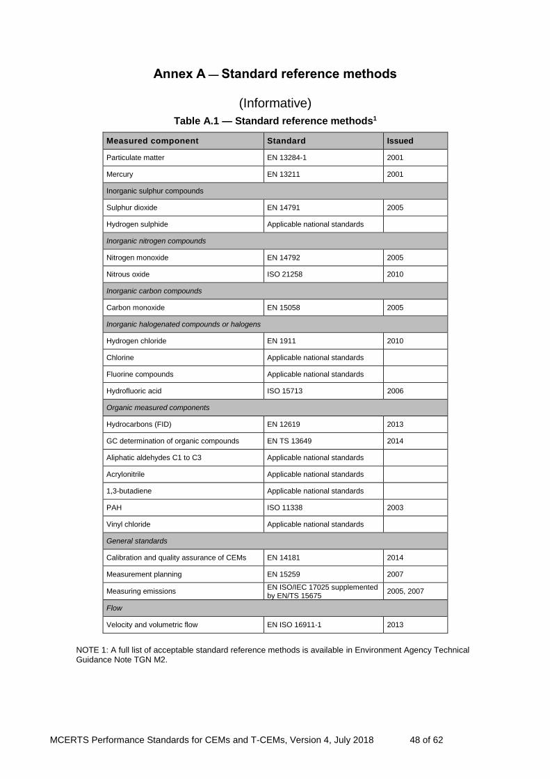
MCERTS Performance Standards for CEMs and T-CEMs, Version 4, July 2018 48 of 62
Annex A — Standard reference methods
(Informative)
Table A.1 — Standard reference methods1
Measured component Standard Issued
Particulate matter EN 13284-1 2001
Mercury EN 13211 2001
Inorganic sulphur compounds
Sulphur dioxide EN 14791 2005
Hydrogen sulphide Applicable national standards
Inorganic nitrogen compounds
Nitrogen monoxide EN 14792 2005
Nitrous oxide ISO 21258 2010
Inorganic carbon compounds
Carbon monoxide EN 15058 2005
Inorganic halogenated compounds or halogens
Hydrogen chloride EN 1911 2010
Chlorine Applicable national standards
Fluorine compounds Applicable national standards
Hydrofluoric acid ISO 15713 2006
Organic measured components
Hydrocarbons (FID) EN 12619 2013
GC determination of organic compounds EN TS 13649 2014
Aliphatic aldehydes C1 to C3 Applicable national standards
Acrylonitrile Applicable national standards
1,3-butadiene Applicable national standards
PAH ISO 11338 2003
Vinyl chloride Applicable national standards
General standards
Calibration and quality assurance of CEMs EN 14181 2014
Measurement planning EN 15259 2007
Measuring emissions EN ISO/IEC 17025 supplemented by EN/TS 15675
2005, 2007
Flow
Velocity and volumetric flow EN ISO 16911-1 2013
NOTE 1: A full list of acceptable standard reference methods is available in Environment Agency Technical Guidance Note TGN M2.

MCERTS Performance Standards for CEMs and T-CEMs, Version 4, July 2018 49 of 65
Annex B — Interferents
(Normative)
Table B.1 — Concentrations of interferents used during cross sensitivity tests
Interferent Concentration
or volume concentration
Value Unit
O2 3 A and 21 %
H2O 30 %
CO 300 mg/m3
CO2 15 %
CH4 50 mg/m3
N2O 20 mg/m3
N2O (fluidised-bed firing) 100 mg/m3
NO 300 mg/m3
NO2 30 mg/m3
NH3 20 mg/m3
SO2 200 mg/m3
SO2 (coal-fired power stations without desulphurisation)
1000 mg/m3
HCI 50 mg/m3
HCI (coal-fired power stations) 200 mg/m3
Note: A test with 3 % oxygen concentration is used instead of test without interferent.
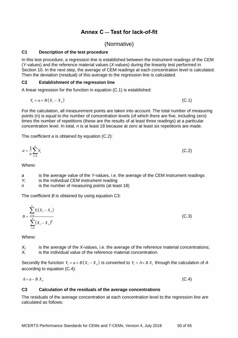
MCERTS Performance Standards for CEMs and T-CEMs, Version 4, July 2018 50 of 65
Annex C — Test for lack-of-fit
(Normative)
C1 Description of the test procedure
In this test procedure, a regression line is established between the instrument readings of the CEM (Y-values) and the reference material values (X-values) during the linearity test performed in Section 10. In the next step, the average of CEM readings at each concentration level is calculated. Then the deviation (residual) of this average to the regression line is calculated.
C2 Establishment of the regression line
A linear regression for the function in equation (C.1) is established:
zii XXBaY (C.1)
For the calculation, all measurement points are taken into account. The total number of measuring points (n) is equal to the number of concentration levels (of which there are five, including zero) times the number of repetitions (these are the results of at least three readings) at a particular concentration level. In total, n is at least 18 because at zero at least six repetitions are made. The coefficient a is obtained by equation (C.2):
n
i
iYn
a
1
1 (C.2)
Where: a is the average value of the Y-values, i.e. the average of the CEM instrument readings Yi is the individual CEM instrument reading n is the number of measuring points (at least 18) The coefficient B is obtained by using equation C3:
n
i
zi
n
i
zii
XX
XXY
B
1
2
1 (C.3)
Where: Xz is the average of the X-values, i.e. the average of the reference material concentrations; Xi is the individual value of the reference material concentration.
Secondly the function zii XXBaY is converted to ii XBAY through the calculation of A
according to equation (C.4):
zXBaA (C.4)
C3 Calculation of the residuals of the average concentrations
The residuals of the average concentration at each concentration level to the regression line are calculated as follows:
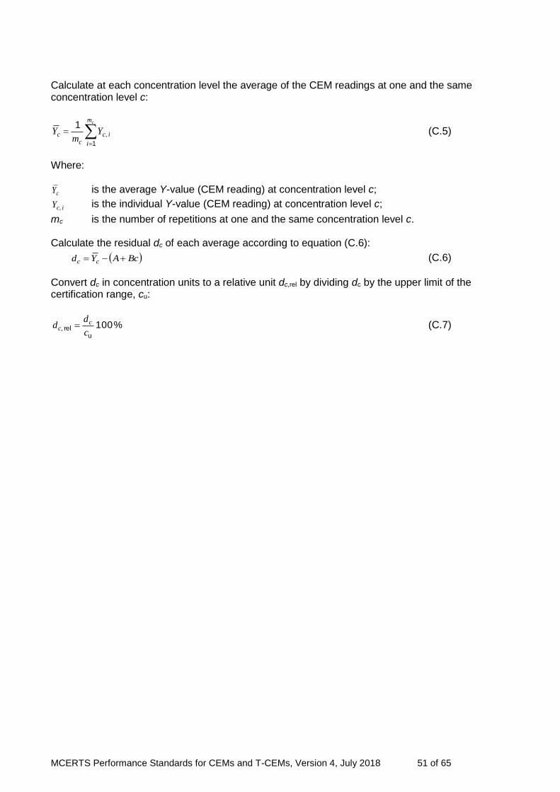
MCERTS Performance Standards for CEMs and T-CEMs, Version 4, July 2018 51 of 65
Calculate at each concentration level the average of the CEM readings at one and the same concentration level c:
cm
i
icc
c Ym
Y
1
,
1 (C.5)
Where:
cY is the average Y-value (CEM reading) at concentration level c;
icY , is the individual Y-value (CEM reading) at concentration level c;
mc is the number of repetitions at one and the same concentration level c.
Calculate the residual dc of each average according to equation (C.6):
BcAYd cc (C.6)
Convert dc in concentration units to a relative unit dc,rel by dividing dc by the upper limit of the certification range, cu:
%100u
rel,c
dd c
c (C.7)

MCERTS Performance Standards for CEMs and T-CEMs, Version 4, July 2018 52 of 65
Annex D — Determination of uncertainties for QAL1
(Normative)
D1 Calculating the uncertainty of the CEM
The performance criteria in this document are presented as expanded uncertainties. The combined standard uncertainties and expanded uncertainties have to be determined according to the requirements of EN ISO 14956. Table D.1 shows the uncertainty contributions which are to be combined when determining the combined standard uncertainty uc. Specific contributions depend on the type of CEM, although some are common to all types of CEM.
Table D1 - Uncertainty contributions
Number Performance characteristic Uncertainty
i ui
1 Lack-of-fit uL
2 Interference uI
3 Span drift from field test ud,s
4 Zero drift from field test ud,z
5 Sensitivity to sample volume flow uv
6 Sensitivity to sample pressure usp
7 Sensitivity to sample temperature ust
8 Sensitivity to ambient temperature ut
9 Dependence on supply voltage usv
10 Repeatability standard deviation at spanA us= sr
11 Reproducibility under field conditionsA uD = sD
12 Uncertainty of the span test gas utg
13 NOx converter efficiency adjustment uNOx
14 Variation of response factors (TOC) uR,TOC
15 Excursion of measurement beam umb
A Either the repeatability at span values or the reproducibility under field conditions is used, whichever is the larger.
If the CEM depends on the regular use of a span test gas for its continued accurate and precise operation – for example, during weekly span checks – then the uncertainty of the test gas shall be included within the calculations. The part of the combined standard uncertainty influenced by the performance characteristics is determined by use of Equation (D.1) and summation of the relevant uncertainty contributions ui specified in Table E.1:
N
i
iuu
1
2c (D.1)

MCERTS Performance Standards for CEMs and T-CEMs, Version 4, July 2018 53 of 65
The total expanded uncertainty U is determined using Equation (D.2): U = 1.96 uc (D.2)
In the above calculation, most the values of ui for a parameter i will be determined from test data, where the probability distribution of values is rectangular for most parameters and a normal distribution for a few parameters. The factor 1.96 may only be used if the number of measurements to determine the uncertainty and the number of degrees of freedom is sufficiently high (for example in the case of rectangular distribution). The standard uncertainties for each performance characteristic (in the case of rectangular distributions) are then calculated according to EN ISO 14956 with Equation (D.3):
3
)()()()()(
2adj,min,adj,max,adj,min,
2adj,max, iiiiiiii
i
xxxxxxxxxu
(D.3)
Where:
min,ix is the minimum value of the influence quantity Xi during the measuring period;
max,ix is the maximum value of the influence quantity Xi during the measuring period;
adj,ix is the value of the influence quantity Xi during the adjustment of the CEM.
Equation (D.3) can be simplified in the following three cases: If the value adj,ix is at the centre of the interval bounded by the maximum value max,ix and the
minimum value min,ix of all values ix , then the standard uncertainty of the values ix is given by
Equation (D.4):
12
)()(
min,max, iii
xxxu
(D.4)
If the absolute values of the measured deviation above and below the central value are equal (see
equation (E.5)), then the standard uncertainty of the values ix is given by Equation (E.6):
iiiii xxxxx adj,min,adj,max, (D.5)
3)( i
ix
xu
(D.6)
If the value of adj,ix is the same as either min,ix or max,ix , then the standard uncertainty of the values
ix is given by Equation (D.7):
3
)()(
min,max, iii
xxxu
(D.7)
D2 Default values for influence quantities
When following the requirements of EN ISO 14956, there are two approaches when applying values for influence quantities. The first is to use default values, which simplifies the calculations, but produces a conservative determination of the uncertainty. For example, the values used during performance testing are used, as opposed to the values for a specific plant. The second approach uses the actual values experienced at a plant. However, in such cases, not
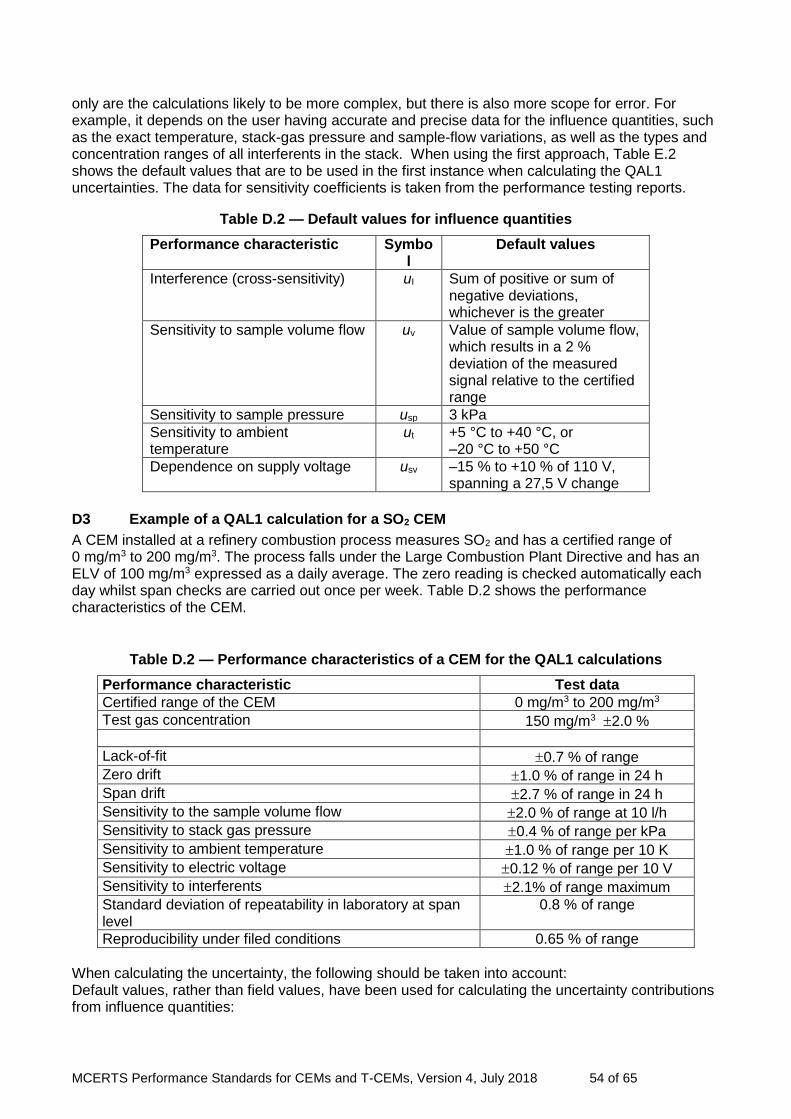
MCERTS Performance Standards for CEMs and T-CEMs, Version 4, July 2018 54 of 65
only are the calculations likely to be more complex, but there is also more scope for error. For example, it depends on the user having accurate and precise data for the influence quantities, such as the exact temperature, stack-gas pressure and sample-flow variations, as well as the types and concentration ranges of all interferents in the stack. When using the first approach, Table E.2 shows the default values that are to be used in the first instance when calculating the QAL1 uncertainties. The data for sensitivity coefficients is taken from the performance testing reports.
Table D.2 — Default values for influence quantities
Performance characteristic Symbol
Default values
Interference (cross-sensitivity) uI Sum of positive or sum of negative deviations, whichever is the greater
Sensitivity to sample volume flow uv Value of sample volume flow, which results in a 2 % deviation of the measured signal relative to the certified range
Sensitivity to sample pressure usp 3 kPa
Sensitivity to ambient temperature
ut +5 °C to +40 °C, or –20 °C to +50 °C
Dependence on supply voltage usv –15 % to +10 % of 110 V, spanning a 27,5 V change
D3 Example of a QAL1 calculation for a SO2 CEM
A CEM installed at a refinery combustion process measures SO2 and has a certified range of 0 mg/m3 to 200 mg/m3. The process falls under the Large Combustion Plant Directive and has an ELV of 100 mg/m3 expressed as a daily average. The zero reading is checked automatically each day whilst span checks are carried out once per week. Table D.2 shows the performance characteristics of the CEM.
Table D.2 — Performance characteristics of a CEM for the QAL1 calculations
Performance characteristic Test data
Certified range of the CEM 0 mg/m3 to 200 mg/m3
Test gas concentration 150 mg/m3 2.0 %
Lack-of-fit 0.7 % of range
Zero drift 1.0 % of range in 24 h
Span drift 2.7 % of range in 24 h
Sensitivity to the sample volume flow 2.0 % of range at 10 l/h
Sensitivity to stack gas pressure 0.4 % of range per kPa
Sensitivity to ambient temperature 1.0 % of range per 10 K
Sensitivity to electric voltage 0.12 % of range per 10 V
Sensitivity to interferents 2.1% of range maximum
Standard deviation of repeatability in laboratory at span level
0.8 % of range
Reproducibility under filed conditions 0.65 % of range
When calculating the uncertainty, the following should be taken into account: Default values, rather than field values, have been used for calculating the uncertainty contributions from influence quantities:

MCERTS Performance Standards for CEMs and T-CEMs, Version 4, July 2018 55 of 65
The standard deviation of the reproducibility under field conditions is smaller than the repeatability standard deviation at span values, so reproducibility is not included in the calculations.
the CEM is dependent on the test gas for continued quality assurance and control, so the uncertainty of the test gas is included in the uncertainty calculations.
Ordinarily either the influence of stack-gas pressure or the influence of sample-gas flow would be included; in this example, both have been included.
Table D.4 shows the uncertainty calculations for each applicable performance characteristic, indicating which equation is used.
Lastly, it should be borne in mind that uncertainty calculations such as this example are estimates.
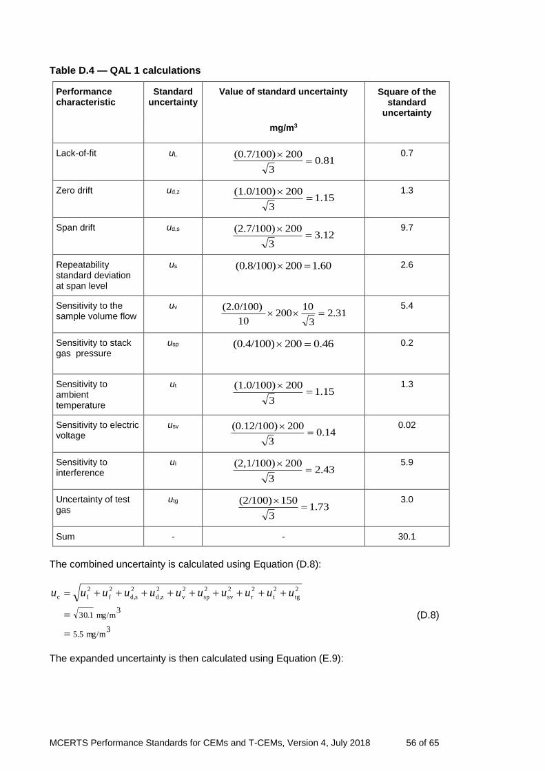
MCERTS Performance Standards for CEMs and T-CEMs, Version 4, July 2018 56 of 65
Table D.4 — QAL 1 calculations
Performance characteristic
Standard uncertainty
Value of standard uncertainty Square of the standard
uncertainty
mg/m3
Lack-of-fit uL 81.0
3
200(0.7/100)
0.7
Zero drift ud,z 15.1
3
200(1.0/100)
1.3
Span drift ud,s 12.3
3
200(2.7/100)
9.7
Repeatability standard deviation at span level
us 60.1200(0.8/100) 2.6
Sensitivity to the sample volume flow
uv 31.2
3
10200
10
(2.0/100)
5.4
Sensitivity to stack gas pressure
usp 46.0200(0.4/100) 0.2
Sensitivity to ambient temperature
ut 15.1
3
200(1.0/100)
1.3
Sensitivity to electric voltage
usv 14.0
3
200(0.12/100)
0.02
Sensitivity to interference
uI 43.2
3
200(2,1/100)
5.9
Uncertainty of test gas
utg 73.1
3
150(2/100)
3.0
Sum - - 30.1
The combined uncertainty is calculated using Equation (D.8):
3mg/m5.5
3mg/m1.30
2
tg
2
t
2
r
2
sv
2
sp
2
v
2
zd,
2
sd,
22
Ic
uuuuuuuuuuu I
(D.8)
The expanded uncertainty is then calculated using Equation (E.9):
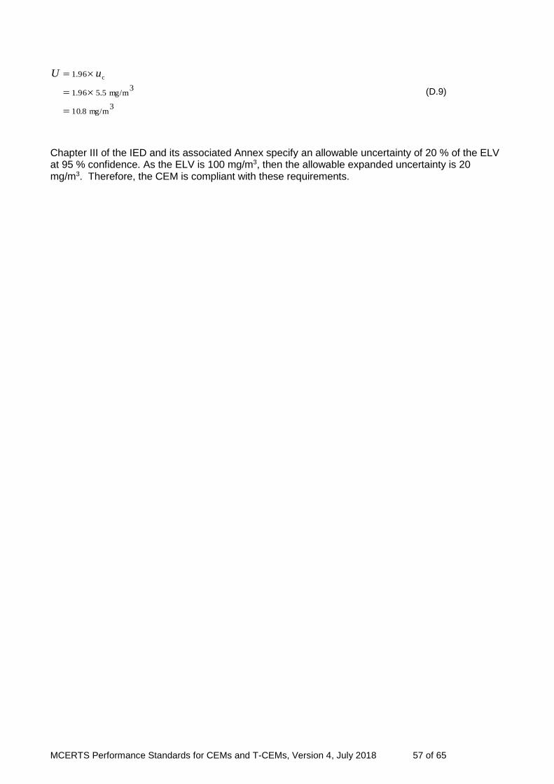
MCERTS Performance Standards for CEMs and T-CEMs, Version 4, July 2018 57 of 65
3mg/m8.10
3mg/m5.596.1
96.1 c
uU
(D.9)
Chapter III of the IED and its associated Annex specify an allowable uncertainty of 20 % of the ELV at 95 % confidence. As the ELV is 100 mg/m3, then the allowable expanded uncertainty is 20 mg/m3. Therefore, the CEM is compliant with these requirements.

MCERTS Performance Standards for CEMs and T-CEMs, Version 4, July 2018 58 of 65
Annex E — Template for a performance testing report
(Normative)
1 General
1.2.1 Certification proposal
1.2.2 Unambiguous CEM designation
1.2.3 Determinand(s)
1.2.4 Device manufacturer together with full address
1.2.5 Field of application
1.2.6 Measuring range for suitability test
1.2.7 Restrictions
Restrictions shall be formulated if testing shows that the CEM does not cover the full scope of possible application fields.
1.2.8 Notes
In the event of supplementary or extended testing, reference shall be made to all preceding test reports. Attention shall de drawn to main equipment peculiarities.
1.2.9 Test laboratory
1.2.10 Test report number and date of compilation
2 Task definition
2.1 Nature of test
First test or supplementary testing.
2.2 Objective
Specification of which performance criteria were tested;
Bibliography;
Scope of any supplementary tests.
3 Description of the CEM tested
3.1 Measuring principle
Description of metrological and scientific relationships.
3.2 CEM scope and set-up
Description of all parts of the CEM covered in the scope of testing, if possible including a copy of an illustration or flow diagram showing the CEM. Statement of technical specifications, if appropriate in tabular form.
4 Test program
Details shall be provided on the test program, in relation to the CEM under test.
In the case of supplementary or extended testing, the additional scope of testing shall be detailed and substantiated.
Particularities of the test shall be documented.
4.1 Laboratory test / laboratory inspection
Statement of all test steps involved
4.2 Field test
Details on:
- all test steps involved;
- plant type on which the field test examinations were carried out;
- CEM measuring range to be covered in the test;
- installation conditions and operating conditions for the CEM under test.
5 Standard reference method
5.1 Method of measurement
MCERTS Performance Standards for CEMs and T-CEMs, Version 4, July 2018 59 of 65
It is necessary to specify the SRM employed. Variations from a SRM, as described in European, international or national standards, shall be documented. Only validated methods shall be used and, as such, a statement on validation shall be made. If, in substantiated cases of exception, continuous CEM are used, details shall be provided on the analyser type, manufacturer, measuring range selected and the suitability test applicable to this equipment type. The standard deviation of the standard reference method shall be stated.
5.2 Test stand set-up
Description of the sampling probe, any dust filters used for particle separation in the measurement of gaseous substances, details on the sample gas line (length, material, size) and on sample gas conditioning.
If continuous CEM are used, the CEM characteristic shall first be examined in accordance with the specifications given in EN 14181. The certified test gases used for this purpose shall be described in respect of their specifications.
6 Test results
Comparison of the performance criteria placed on continuous emission CEM in the suitability test with the results attained.
The information below shall be stated for each individual test point in the following order of sequence:
Consecutive number and short title of performance criteria as heading.
6.1 Citation of performance criterion
6.2 Equipment
6.3 Method
6.4 Evaluation
6.5 Assessment
6.6 Detailed presentation of test results allowing for the respective section of the documentation
Annex A Values measured and computed
Annex B Operating instructions
The operating instructions should also be enclosed with the report in electronic form (for example as a PDF file).
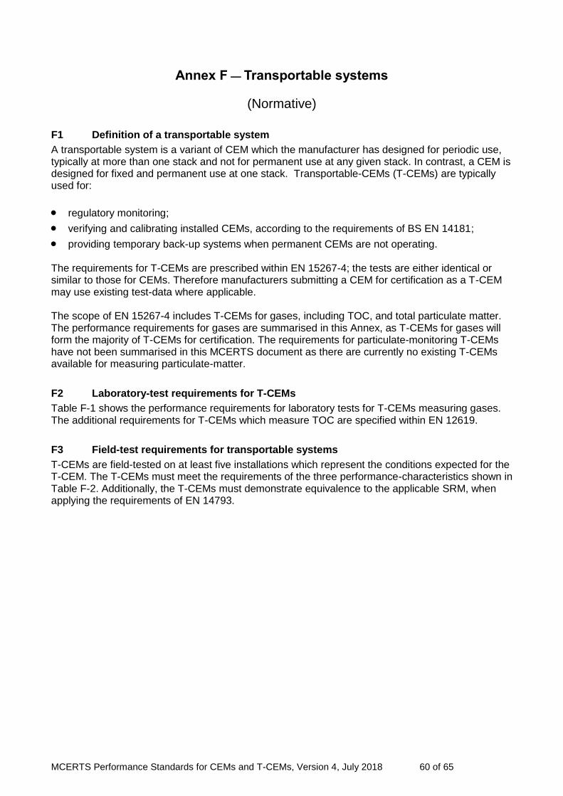
MCERTS Performance Standards for CEMs and T-CEMs, Version 4, July 2018 60 of 65
Annex F — Transportable systems
(Normative)
F1 Definition of a transportable system
A transportable system is a variant of CEM which the manufacturer has designed for periodic use, typically at more than one stack and not for permanent use at any given stack. In contrast, a CEM is designed for fixed and permanent use at one stack. Transportable-CEMs (T-CEMs) are typically used for:
regulatory monitoring;
verifying and calibrating installed CEMs, according to the requirements of BS EN 14181;
providing temporary back-up systems when permanent CEMs are not operating. The requirements for T-CEMs are prescribed within EN 15267-4; the tests are either identical or similar to those for CEMs. Therefore manufacturers submitting a CEM for certification as a T-CEM may use existing test-data where applicable. The scope of EN 15267-4 includes T-CEMs for gases, including TOC, and total particulate matter. The performance requirements for gases are summarised in this Annex, as T-CEMs for gases will form the majority of T-CEMs for certification. The requirements for particulate-monitoring T-CEMs have not been summarised in this MCERTS document as there are currently no existing T-CEMs available for measuring particulate-matter.
F2 Laboratory-test requirements for T-CEMs
Table F-1 shows the performance requirements for laboratory tests for T-CEMs measuring gases. The additional requirements for T-CEMs which measure TOC are specified within EN 12619.
F3 Field-test requirements for transportable systems
T-CEMs are field-tested on at least five installations which represent the conditions expected for the T-CEM. The T-CEMs must meet the requirements of the three performance-characteristics shown in Table F-2. Additionally, the T-CEMs must demonstrate equivalence to the applicable SRM, when applying the requirements of EN 14793.
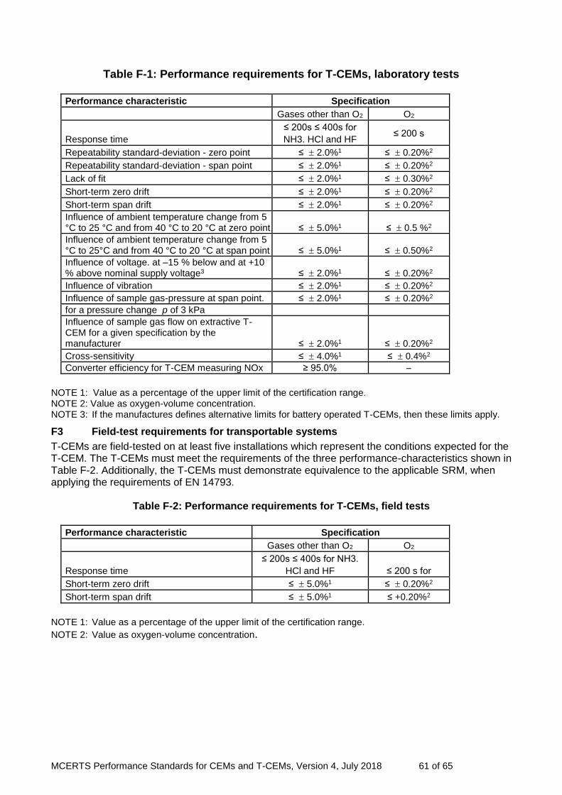
MCERTS Performance Standards for CEMs and T-CEMs, Version 4, July 2018 61 of 65
Table F-1: Performance requirements for T-CEMs, laboratory tests
Performance characteristic Specification
Gases other than O2 O2
Response time
≤ 200s ≤ 400s for
NH3. HCl and HF ≤ 200 s
Repeatability standard-deviation - zero point ≤ 2.0%1 ≤ 0.20%2
Repeatability standard-deviation - span point ≤ 2.0%1 ≤ 0.20%2
Lack of fit ≤ 2.0%1 ≤ 0.30%2
Short-term zero drift ≤ 2.0%1 ≤ 0.20%2
Short-term span drift ≤ 2.0%1 ≤ 0.20%2
Influence of ambient temperature change from 5 °C to 25 °C and from 40 °C to 20 °C at zero point ≤ 5.0%1 ≤ 0.5 %2
Influence of ambient temperature change from 5 °C to 25°C and from 40 °C to 20 °C at span point ≤ 5.0%1 ≤ 0.50%2
Influence of voltage. at –15 % below and at +10 % above nominal supply voltage3 ≤ 2.0%1 ≤ 0.20%2
Influence of vibration ≤ 2.0%1 ≤ 0.20%2
Influence of sample gas-pressure at span point. ≤ 2.0%1 ≤ 0.20%2
for a pressure change p of 3 kPa
Influence of sample gas flow on extractive T- CEM for a given specification by the manufacturer ≤ 2.0%1 ≤ 0.20%2
Cross-sensitivity ≤ 4.0%1 ≤ 0.4%2
Converter efficiency for T-CEM measuring NOx ≥ 95.0% –
NOTE 1: Value as a percentage of the upper limit of the certification range. NOTE 2: Value as oxygen-volume concentration. NOTE 3: If the manufactures defines alternative limits for battery operated T-CEMs, then these limits apply.
F3 Field-test requirements for transportable systems
T-CEMs are field-tested on at least five installations which represent the conditions expected for the T-CEM. The T-CEMs must meet the requirements of the three performance-characteristics shown in Table F-2. Additionally, the T-CEMs must demonstrate equivalence to the applicable SRM, when applying the requirements of EN 14793.
Table F-2: Performance requirements for T-CEMs, field tests
Performance characteristic Specification
Gases other than O2 O2
Response time
≤ 200s ≤ 400s for NH3.
HCl and HF ≤ 200 s for
Short-term zero drift ≤ 5.0%1 ≤ 0.20%2
Short-term span drift ≤ 5.0%1 ≤ +0.20%2
NOTE 1: Value as a percentage of the upper limit of the certification range.
NOTE 2: Value as oxygen-volume concentration.

MCERTS Performance Standards for CEMs and T-CEMs, Version 4, July 2018 62 of 65
Annex G — Classes of particulate-monitoring CEMs - allowable uses
(Informative)
Table G1 – Classes of particulate monitoring CEMs and their allowable uses
Class 1 2 3
Output - Quantitative, output can be calibrated in mg.m-3
Output - Qualitative 1
1
QAL1 compliant (EN 14181)
Use for installations falling under Chapters III and IV of the IED2
Use for PPC installations other than those under Chapters III and IV of the IED2 Chapters III and IV of the IED2 where the emissions may normally exceed 50% of the ELV
Use for PPC installations other than those under Chapters III and IV of the IED2, where the emissions do not normally exceed 50% of the ELV
1
Use for PPC installations where there is no ELV in mg.m-
3, to monitor changes in performance of dust-arrestment plant and alarm in the event of failure.
1
1
1 Although the classes of monitors may be used for these applications, the performance of the class of monitoring system
exceeds the actual requirements. 2 Industrial Emissions Directive (2010/75/EU). Chapter III applies to large combustion plants whilst Chapter IV applies to
waste incineration plants.
G1 The three classes of particulate monitor
Class 1 – Particulate monitors used for measuring emissions in mg. m-3. Class 1 monitors meet the requirements of EN 14181, specifically for QAL1 and QAL3. Operators of installations falling under Chapters III and IV of the Industrial Emissions Directive (IED), for large combustion plant and incineration respectively, must use Class 1 particulate monitors. Class 1 monitors may also be used on all other PPC installations.
Class 2 – Filter Dust Monitors: Particulate monitors used for measuring emissions in mg.m-3. Class 2 monitors may be used with our agreement on PPC installations other than large combustion plant and incineration where the emissions are normally less than 50% of the emission limit value. Such monitors are used to provide feedback that a process is under control and stable and operating well within the emission limit value.
Class 3 – Filter Leakage Monitors: Dust-arrestment plant-monitors used to monitor changes in performance of dust-arrestment plant and alarm in the event of failure. They provide an indication of particulate emissions but do not measure emissions in mg.m-3.
Note: Both the performance specifications and test procedures for Class 2 and Class 3 particulate-monitoring CEMs are described in the MCERTS performance standards for the MCERTS Certification of automated dust arrestment-plant monitors – Performance criteria and test procedures, according to EN 15859.
MCERTS Performance Standards for CEMs and T-CEMs, Version 4, July 2018 63 of 65
Annex H — Calibration of Class 2 and Class 3 particulate monitors
(Informative)
H1 Class 2 CEMs - Procedure for calibrating particulate CEMs when either SRM data or surrogates are valid
A test laboratory should initially apply BS ISO 10155 for calibrating Class 2 CEMs
If the data is spread over a range with a value which is greater than 15% of the ELV, then the test laboratory shall determine a calibration function and apply this to CEM, according to the requirements of BS ISO 10155.
If the data is clustered, such that the data is spread over a range with a value which is l5% or less than the ELV, then the CEM should be calibrated by taking an average of the data points, and forcing a calibration line from this average point through zero.
Test laboratories shall take five samples initially and three samples thereafter. The test laboratory may also combine historical and current data-points in the calibration function, provided that the subsequent data-points lie within the 95% confidence intervals of the calibration function.
The test laboratory may find, however, that it is not possible to determine a meaningful calibration function; for example, when most or all of the reported PM values are at or near zero. If so, then the test laboratory shall do the following in lieu of the variability test specified in EN 14181:
Determine an average and standard deviation for the CEM data and SRM data.
Compare the averages of the CEM data and SRM by using the 95% confidence interval specified in applicable Directives.
The results are acceptable if both averages lie within the 95% confidence interval.
H2 Using surrogates – Class 2 CEMs
Surrogates have two roles:
Calibrating CEMs if this is possible
Determining stability through zero and span tests. Although surrogates for PM CEMs are limited and can be inaccurate, they are the best practicable option available if there is insufficient SRM data to calibrate a CEM, but only when the response of the CEM to the surrogate is proportional to a known particulate concentration. However, because of the nature of PM, this is rare.

MCERTS Performance Standards for CEMs and T-CEMs, Version 4, July 2018 64 of 65
H3 Setting up CEMs if surrogates cannot be used to calibrate the CEM – Calibration of Class 2 and Class 3 CEMs
There will be situations when calibration is impossible, due to:
Low clusters of emissions, meaning that the data does not meet the requirements of ISO 10155.
Surrogates may be useful for zero, span and linearity tests, but the resultant data cannot be meaningfully related to concentrations of particulate.
In such cases, the particulate monitor cannot be used as a quantitative monitor for particulate, but can serve as a qualitative indicator. Therefore if the emissions are consistently low, we recommend that:
The SRM is used to verify that the emissions are low.
Surrogates are used to check the linearity, and zero and span settings of the monitor.
The monitor is set on its most sensitive range, in order to alert the operator when the control devices for particulate may need attention.
This procedure should also be used to set up Class 3 CEMs.
MCERTS Performance Standards for CEMs and T-CEMs, Version 4, July 2018 65 of 65
Bibliography Directive covering processes emitting greenhouse gases (2003/87/EC) Directive on industrial emissions (integrated pollution prevention and control) (Recast)(2010/75/EC) Directive relating to electromagnetic compatibility and repealing Directive 89/336/EEC (EMC Directive)(2004/108/EC) Directive 2006/95/EC on the harmonisation of the laws of Member States relating to electrical equipment designed for use within certain voltage limits (Low Voltage Directive)(2006/95/EC) Directive 2014/35/EU on the harmonisation of the laws of the Member States relating to the making available on the market of electrical equipment designed for use within certain voltage limits (Low Voltage Directive)(2014/35/EC) EN ISO 9169:2006, Air Quality – Definition and determination of performance characteristics of an automatic measuring system ISO 5725-2:1994, Accuracy (trueness and precision) of measurement methods and results - Part 2: Basic method for the determination of repeatability and reproducibility of a standard measurement method EN/TS 15675:2007, Air quality – Measurement of stationary source emissions – Application of EN ISO/IEC 17025:2000 to periodic stack measurements EN 15859:2010 - Air Quality – Certification of automated dust arrestment plant monitors for use on stationary sources – Performance criteria and test procedures EN ISO/IEC 17065:2012 - Conformity assessment – Requirements for bodies certifying products, processes and services BS ISO 10155:1995 – Stationary source emissions. Automated monitoring of mass concentrations of particles. Performance characteristics, test methods and specifications.
LIT 7071