Performance of Star 16/64QAM Schemes Using Turbo … · Performance of Star 16/64QAM Schemes Using...
9
126 Journal of Communications Vol. 9, No. 2, February 2014 ©2014 Engineering and Technology Publishing Performance of Star 16/64QAM Schemes Using Turbo FDE with Iterative Decision-Directed Channel Estimation for DFT-Precoded OFDMA Chihiro Mori 1 , Mamoru Sawahash 1 , Teruo Kawamura 2 , and Nobuhiko Miki 3 1 Tokyo City University, Tokyo, Japan 2 NTT Docomo INC., Yokosuka, Japan 3 Kagawa University, Takamatsu, Japan Email: [email protected]; [email protected], [email protected], [email protected] Abstract—This paper presents the average block error rate (BLER) performance of star 16/64QAM schemes using iterative decision-directed channel estimation (IDDCE) associated with the turbo frequency domain equalizer (FDE) for discrete Fourier transform (DFT)-precoded Orthogonal Frequency Division Multiple Access (OFDMA). We show that the turbo FDE with the IDDCE based on the a posteriori log-likelihood ratio (LLR) decreases the required average received signal-to-noise power ratio (SNR) compared to that based on the extrinsic LLR. We also show that the turbo FDE is effective in decreasing the required average received SNR considering the cubic metric (CM) compared to the linear minimum mean-square error based FF-FDE for star 16/64QAM schemes. Moreover, we show that the (8, 8) star 16QAM and (16, 16, 16, 16) star 64QAM schemes decrease the required average received SNR considering the CM at the average BLER of 10 -2 by approximately 0.8 and 0.3 dB compared to the square 16QAM and 64QAM schemes, respectively, with a low turbo coding rate such as R = 1/3 when using the turbo FDE associated with IDDCE. Index Terms—single-carrier FDMA; turbo FDE; iterative channel estimation; star QAM; DFT-precoded OFDMA I. INTRODUCTION Single-carrier (SC)-Frequency Division Multiple Access (FDMA) is adopted in the Long-Term Evolution (LTE) uplink due to its low peak-to-average power ratio (PAPR) feature [1]. Discrete Fourier transform (DFT)- precoded Orthogonal Frequency Division Multiple Access (OFDMA) is adopted to generate SC-FDMA signals in the frequency domain [2], [3] to achieve high commonality with OFDMA in the downlink and affinity to frequency domain equalizers (FDEs) [4], [5]. In adaptive modulation and coding (AMC), high-level modulation schemes including 16QAM and 64QAM are employed near a cell site under high-received signal-to- interference plus noise power ratio (SINR) conditions. Square 16/64QAM schemes are usually employed because they have the longest Euclidean distances among constellation signals [6]. Recently, the star 16QAM scheme [7] has drawn attention due to its merit, i.e., the fluctuation in amplitude is smaller than that for the square Manuscript received September 10, 2013; revised February 15, 2014. 16QAM scheme. It was clarified in [8] that the (8, 8) star 16QAM scheme achieves a lower required average received signal-to-noise power ratio (SNR) considering the cubic metric (CM) [9] that satisfies the target block error rate (BLER) compared to the square 16QAM scheme with a low channel coding rate. Similarly, an efficient modulation scheme with low peak transmission power is necessary for 32QAM and 64QAM schemes. The bit error rate (BER) performance of the star 16QAM scheme and that for the star 32QAM schemes with turbo coding considering non-linearity of the power amplifier (PA) for satellite communications were reported in [10]. Note that star QAM is referred to as amplitude and phase shift keying (APSK) in satellite communications. In this paper, we use the notation of star QAM. In [10], the optimum constellation for the 32APSK scheme was investigated. The optimum constellation for the 64APSK scheme was investigated in [11]. In these papers, the achievable throughput was investigated based on the maximum error-free data rate using mutual information (MI). However, the average BER or BLER performance in a multipath Rayleigh fading channel is not necessarily identical to the results based on MI. This is because the amplitude component is much weaker than the phase component in a multipath Rayleigh fading channel. Hence, we investigated the average BLER performance levels of star 32QAM and 64QAM schemes considering the CM based on a comparison to those of cross 32QAM and square 64QAM schemes, respectively [12]. In general, a one-tap linear filter based on the linear minimum mean-square error (LMMSE) criterion is used in a FDE [4], [5]. In the paper, we refer to the LMMSE based FDE as a feed forward-FDE (FF-FDE). To decrease the residual equalization error of the LMMSE based FF-FDE, a turbo FDE was proposed [13]-[16] that involves frequency domain processing of the turbo equalizer [17]. A turbo FDE comprises a FF-FDE and a decision feedback-FDE (DFB-FDE). The DFB-FDE generates a soft-symbol estimate from the extrinsic probability of the log-likelihood ratio (LLR) at the decoder output and the residual error signal of the FF- FDE in the frequency domain. By subtracting the estimated error signal from the FF-FDE output signal, the doi:10.12720/jcm.9.2.126-134
Transcript of Performance of Star 16/64QAM Schemes Using Turbo … · Performance of Star 16/64QAM Schemes Using...

126
Journal of Communications Vol. 9, No. 2, February 2014
©2014 Engineering and Technology Publishing
Performance of Star 16/64QAM Schemes Using Turbo
FDE with Iterative Decision-Directed Channel Estimation
for DFT-Precoded OFDMA
Chihiro Mori1, Mamoru Sawahash
1, Teruo Kawamura
2, and Nobuhiko Miki
3
1Tokyo City University, Tokyo, Japan
2NTT Docomo INC., Yokosuka, Japan
3Kagawa University, Takamatsu, Japan
Email: [email protected]; [email protected], [email protected], [email protected]
Abstract—This paper presents the average block error rate
(BLER) performance of star 16/64QAM schemes using iterative
decision-directed channel estimation (IDDCE) associated with
the turbo frequency domain equalizer (FDE) for discrete Fourier
transform (DFT)-precoded Orthogonal Frequency Division
Multiple Access (OFDMA). We show that the turbo FDE with
the IDDCE based on the a posteriori log-likelihood ratio (LLR)
decreases the required average received signal-to-noise power
ratio (SNR) compared to that based on the extrinsic LLR. We
also show that the turbo FDE is effective in decreasing the
required average received SNR considering the cubic metric
(CM) compared to the linear minimum mean-square error based
FF-FDE for star 16/64QAM schemes. Moreover, we show that
the (8, 8) star 16QAM and (16, 16, 16, 16) star 64QAM
schemes decrease the required average received SNR
considering the CM at the average BLER of 10-2 by
approximately 0.8 and 0.3 dB compared to the square 16QAM
and 64QAM schemes, respectively, with a low turbo coding rate
such as R = 1/3 when using the turbo FDE associated with
IDDCE. Index Terms—single-carrier FDMA; turbo FDE; iterative
channel estimation; star QAM; DFT-precoded OFDMA
I. INTRODUCTION
Single-carrier (SC)-Frequency Division Multiple
Access (FDMA) is adopted in the Long-Term Evolution
(LTE) uplink due to its low peak-to-average power ratio
(PAPR) feature [1]. Discrete Fourier transform (DFT)-
precoded Orthogonal Frequency Division Multiple
Access (OFDMA) is adopted to generate SC-FDMA
signals in the frequency domain [2], [3] to achieve high
commonality with OFDMA in the downlink and affinity
to frequency domain equalizers (FDEs) [4], [5]. In adaptive modulation and coding (AMC), high-level
modulation schemes including 16QAM and 64QAM are
employed near a cell site under high-received signal-to-
interference plus noise power ratio (SINR) conditions. Square 16/64QAM schemes are usually employed
because they have the longest Euclidean distances among
constellation signals [6]. Recently, the star 16QAM
scheme [7] has drawn attention due to its merit, i.e., the
fluctuation in amplitude is smaller than that for the square
Manuscript received September 10,
2013; revised February
15, 2014.
16QAM scheme. It was clarified in [8] that the (8, 8) star
16QAM scheme achieves a lower required average
received signal-to-noise power ratio (SNR) considering
the cubic metric (CM) [9] that satisfies the target block
error rate (BLER) compared to the square 16QAM
scheme with a low channel coding rate. Similarly, an
efficient modulation scheme with low peak transmission
power is necessary for 32QAM and 64QAM schemes.
The bit error rate (BER) performance of the star 16QAM
scheme and that for the star 32QAM schemes with turbo
coding considering non-linearity of the power amplifier
(PA) for satellite communications were reported in [10].
Note that star QAM is referred to as amplitude and phase
shift keying (APSK) in satellite communications. In this
paper, we use the notation of star QAM. In [10], the
optimum constellation for the 32APSK scheme was
investigated. The optimum constellation for the 64APSK
scheme was investigated in [11]. In these papers, the
achievable throughput was investigated based on the
maximum error-free data rate using mutual information
(MI). However, the average BER or BLER performance
in a multipath Rayleigh fading channel is not necessarily
identical to the results based on MI. This is because the
amplitude component is much weaker than the phase
component in a multipath Rayleigh fading channel.
Hence, we investigated the average BLER performance
levels of star 32QAM and 64QAM schemes considering
the CM based on a comparison to those of cross 32QAM
and square 64QAM schemes, respectively [12].
In general, a one-tap linear filter based on the linear
minimum mean-square error (LMMSE) criterion is used
in a FDE [4], [5]. In the paper, we refer to the LMMSE
based FDE as a feed forward-FDE (FF-FDE). To
decrease the residual equalization error of the LMMSE
based FF-FDE, a turbo FDE was proposed [13]-[16] that
involves frequency domain processing of the turbo
equalizer [17]. A turbo FDE comprises a FF-FDE and a
decision feedback-FDE (DFB-FDE). The DFB-FDE
generates a soft-symbol estimate from the extrinsic
probability of the log-likelihood ratio (LLR) at the
decoder output and the residual error signal of the FF-
FDE in the frequency domain. By subtracting the
estimated error signal from the FF-FDE output signal, the doi:10.12720/jcm.9.2.126-134
127
Journal of Communications Vol. 9, No. 2, February 2014
©2014 Engineering and Technology Publishing
turbo FDE achieves a higher BLER performance level
compared to FF-FDE. In [18], the improvement in the
average BLER performance of the turbo FDE compared
to the FF-FDE was shown particularly for 16QAM and
64QAM assuming ideal channel estimation (CE) for
DFT-precoded OFDMA. In the turbo FDE, the estimation
accuracy of the channel responses affects the achievable
BLER performance level. Hence, iterative decision-
directed channel estimation (IDDCE) associated with the
turbo FDE was proposed and its performance was
investigated for QPSK and square QAM schemes for
DFT-precoded OFDMA [19].
This paper presents the average BLER performance of
the star 16/64QAM schemes employing a FDE and
IDDCE for DFT-precoded OFDMA. By using soft-
symbol replicas based on the extrinsic LLR at the Max-
Log-MAP (maximum a posteriori probability) decoder
output and a reference signal (RS), the accuracy of the
channel response is improved in the iterative inner loop
employing the FF-FDE at an iteration of the outer loop of
the turbo FDE. The operational principle of the IDDCE is
the same as that in [19]. In general, the soft-symbol
estimate for the turbo FDE and IDDCE is generated from
the LLR of the extrinsic probability (extrinsic LLR) of
each bit at the decoder output. Recently, it was reported
in [20] and [21] that for multiple-input multiple-output
(MIMO) spatial division multiplexing (SDM), the turbo
soft interference canceller (SIC) using a soft-symbol
estimate based on the a posteriori LLR achieves better
BER or BLER performance compared to that with a soft-
symbol estimate based on the extrinsic LLR. Hence, we
investigate the BLER performance of a turbo FDE with
IDDCE using a soft-symbol estimate based on the a
posteriori LLR or extrinsic LLR. Moreover, we consider
a CM, which is an empirical criterion corresponding to
the transmission back-off of the transmitter PA [9]. Then,
under the best IDDCE conditions, we compare the
average BLER performance levels of the star 16/64QAM
schemes using the turbo FDE compared to those of the
square 16/64QAM in a frequency-selective Rayleigh
fading channel. The rest of the paper is organized as
follows. First, Section II describes the transmitted signal
representation. Section III gives details on the structure of
the turbo FDE. Section IV presents the operation of the
IDDCE with the selection of soft-symbol estimations.
Then, Section V describes the computer simulation
evaluation followed by Section VI which gives our
concluding remarks.
II. TRANSMITTED SIGNAL REPRESENTATION
Fig. 1 shows the transmitter structure for SC-FDMA
using DFT-precoded OFDMA. An information bit stream
is channel-encoded using a turbo code with the coding
rate of R = 1/3 and with the constraint length of 4 bits.
The generator polynomials of R = 1/3 turbo code are
given as G = [1, g1/g0] and (g1/g0), where g0 = [1011] and
g1 = [1101]. A higher coding rate than R = 1/3 is
generated by puncturing the parity bit for the R = 1/3
code. The bit-interleaver within the duration of one
subframe permutes the coded bits. The coded bit
sequence after interleaving is partitioned into L blocks.
The coded bits after interleaving are given as
TT
Kl
T
kl
T
l 1,,0, cccc (l = 0,…, L - 1) in vector notation,
which consists of K sets of M code bits
TMklklkl cc 1,,0,,, c (the notation of [·]T denotes
transposition). Here, the K value corresponds to the
number of data-modulated symbols within one FFT block.
It also corresponds to the number of subcarriers. In a
modulation mapping block, the coded bit is mapped into
symbol sequence klklx ,, c among the M-ary
constellation to generate a symbol vector with the length
of K, TKlklll xxx 1,,0, x , where lx denotes the l-th
block of x . The mapping function, , performs mapping
of code bits according to a 2M
-ary symbol alphabet
120
MssS , where each si (i = 0,…, 2M
-1)
corresponds to a binary bit pattern, 1,0, ,1,0, jiMii bbb .
We assume the 16QAM or 64QAM modulation scheme,
i.e., M = 4 or 6.
DF
T
Su
bca
rrie
rm
app
ing
Turbo encoder
Transmitted bits
Modulation mapping
Transmittedsignals
IFF
T CPinsertion
Bitinterleaver
Fig. 1. Transmitter structure.
0001
00100011
0100
0101
0110
0111
0000
10001001
1010
1011
1100
1101
1110
1111r1
r2
ra = r2 / r1)
(b) (4, 12) Star 16QAM
0001
0100
0101
0010
0011
0110
0111
0000
1000
1001
1100
1101
10101011
1110
1111
r1
r2
(ra = r2 / r1)
(a) (8, 8) Star 16QAM
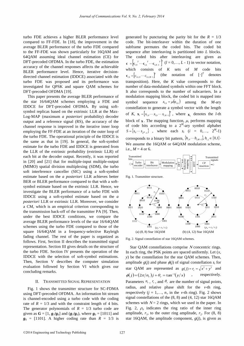
Fig. 2. Signal constellation of star 16QAM schemes.
Star QAM constellations comprise concentric rings.
In each ring, the PSK points are spaced uniformly. Let (x,
y) be the constellation for the star QAM schemes. Then,
amplitude g(j) and phase (j) of signal constellation si for
star QAM are represented as 22)( yxrjg and
xyθjnj 1tan2 , respectively.
Parameters n , r , and are the number of signal points,
radius, and relative phase shift for the -th ring,
respectively (j = 1,…, n in the -th ring). Fig. 2 shows
signal constellations of the (8, 8) and (4, 12) star 16QAM
schemes with = 2 rings, which we used in the paper. In
Fig. 2, ra indicates the ring ratio of the inner ring
amplitude, r1, to the outer ring amplitude, r2. For (8, 8)
star 16QAM, the amplitude component, g(j), is given as

128
Journal of Communications Vol. 9, No. 2, February 2014
©2014 Engineering and Technology Publishing
21/8)( arjg r where r is 1 and ra for the inner and
outer rings, respectively. The phase component is given
as 4/ j , where = 0, 1, …, 7. Similarly, for the
(4, 12) star 16QAM, the amplitude is given as 231/16)( arjg r . The phase component is given as
2/j , where = 1 and = 0, 1, 2, 3 for the
inner ring, and = 3 and = 0, 1,…, 11 for the outer ring.
Moreover, for the star 64QAM schemes, we investigate 2
types of signal constellations, i.e., (8, 24, 32) for M = 3
and (16, 16, 16, 16) for M = 4. Fig. 3 shows a signal
constellation for the (16, 16, 16, 16) star 64QAM scheme.
The ring ratios of the (16, 16, 16, 16) star 64QAM
scheme are defined as 12 rra r , 13 rrb r , and
14 rrc r .
010111
000000 000001 000011 000010
000110
001100
001111
001101
000100
001110
001010
001011
000101
000111001000
001001
011110
011010
011011
011001
011000
010000
011101
011111
010010
010011
010001
011100
010110
010101
010100
100000
100010
100011
100110
100001
101101
100100101100
101111
100101
101001
101010
101011
101110
101000
110000
111110
111010
111011
111001
111000
111100
111101
111111
110101
110100
110001110011110010
110110
110111
100111
r3
r2
r1
r4
ra = r2 / r1)
Fig. 3. Signal constellation of (16, 16, 16, 16) star 64QAM schemes.
Data-modulated symbol klx , is mapped into the t-th
FFT block ( 11,4,14,...,1 tt ) as ktx , . Note that the
modulation phase is known at the receiver for the RS
symbols for t = 4 and 11. The data-modulated symbol
sequence in the t-th FFT block is converted by the K-
point DFT, KF , into a frequency domain signal with K
components (subcarriers), tKt xFX , where
TKtkttt XXX 1,,0, X (we use a subcarrier index that
is the same as the symbol index in a FFT block for
simplicity). In the computer simulation evaluation in
Section V, we set K = 60, i.e., the transmission bandwidth
is BTx = 5 RBs (900 kHz). In the subcarrier mapping part,
the symbol vector, tX , is mapped into the assigned
transmission bandwidth. The operation of the subcarrier
mapping is expressed as an NFFT x K matrix,
KN FFTQ KNFFT , where NFFT denotes the number of
points for the following inverse FFT (IFFT). Matrix
KN FFTQ is given as TKKzNKKzKN FFTFFT 0I0Q ,
where z ( 1,...1,0 KNz FFT ) represents the subcarrier
position in which the 0-th subcarrier of the K-subcarrier
signal is assigned and IK denotes the K x K identity
matrix. Parameter NFFT is set to 1024. After padding
(NFFT - K) zeros, the IFFT converts the frequency-domain
signal into a time-domain signal as tKNNt FFTFFTXQFs
1.
Here, 1
FFTNF indicates the IFFT matrix. Finally, a CP is
appended to each FFT block to avoid inter-block
interference.
III. TURBO FDE
Fig. 4 shows the receiver structure including a turbo
FDE and IDDCE. At the receiver, two-branch antenna
diversity reception is assumed. We assume ideal FFT
timing detection. Let TFFTmmm Nrr 1,,0 r be the
received signal block within a subframe at the m-th
receiver branch (m = 1, 2). It is given in matrix notation
as
mm
s
smmm
T
Endhnshr
2 (1)
where s is the transmitted signal vector, d is the
transmitted symbol vector, nm is the noise vector
comprising an element with zero mean and the variance
of 2, and hm is the circulant matrix of the channel
impulse response with the size of NFFT × NFFT. The
received signal block is transformed into frequency
domain signal vector TFFTmmm NRR )1(,),0( R by the
FFT and is expressed as
mm
s
smm
T
ENDHFrR
2 (2)
where H
mm FFhH is the channel matrix in the
frequency domain, D = Fd is the frequency domain signal
vector, Nm = Fnm is the frequency domain noise vector, F
is the FFT matrix with the size NFFT × NFFT, and (·)H
denotes the Hermitian transpose operation. The u-th
frequency component, Rm(u), of Rm at the m-th receiver
branch is given as
)()()(2
)( uNuDuHT
EuR mm
s
sm (3)
where FFTlml
L
lm NujhuH 2exp)( ,
1
0
, )(uD
FFT
N
tFFT NutjtdN FFT 2exp)(11
0
, and )(uNm
FFTm
N
tFFT NutjtnN FFT 2exp)(11
0
. In addition, hp,m
and p represent the channel impulse response for the p-th
path at the m-th receiver branch and the delay for the p-th
path, respectively. Then, we obtain k subcarriers
including the desired signal from u samples by removing
(NFFT K) subcarriers in the frequency domain.
Rx #2
Rx #1
FFT
mpq
klW ,
,
+-
Max-Log-MAP decoder
pq
klB ,
,
IDFT
DFTSoft-symbol
estimate
)1,(
,ˆ pq
klXAverage of channel responses
Received signal
De-interleaver
Interleaver
IDDCE
itrNp Outer loop for turbo FDE
Inner loop for IDDCE
Fig. 4. Receiver structure including turbo FDE and IDDCE.

129
Journal of Communications Vol. 9, No. 2, February 2014
©2014 Engineering and Technology Publishing
Let mq
kH be the estimated channel response at the k-th
subcarrier after de-mapping in a subframe at the m-th
receiver branch for the q-th iteration of the turbo FDE
( TFDE
itrNq 1 ). Then, the LMMSE based FF-FDE weight
is given as [18], [22]
q
m
mq
k
qmq
k
qmq
k HHW rr
1
0'
2'212*21 11
(4)
In (4), received SNR q
is given as
2
1
12121
m
xK
ku
m
k
mq
k
q HWxK (5)
Moreover, qr is the error correlation of the decoded
bit in the previous iteration loop and is defined as
2
,
*
,,ˆ
klkl
q
kl
q xExxEr [23]. At the initial iteration of the
turbo FDE, the FF-FDE weight is given as
22
'11
0
*11 m
km
m
k
m
k HHW . We assume ideal
estimation of the noise power, 2, in the denominator of
the FF-FDE weight. Then, the k-th subcarrier, m
klR , , after
frequency domain equalization and coherently combining
of receiver branches is obtained as
mq
kkl
mq
k
s
s
m
m
kl
mq
k
q
kl NDHT
ERWR ˆˆ2ˆ
,
1
0
,,
, (6)
where mq
k
mq
km
q
k HWH 1
0ˆ
and
m
kl
mq
km
q
kl NWN ,
1
0,ˆ
are the equivalent channel response and noise component
after frequency domain equalization. An inverse DFT
(IDFT) converts the frequency domain signal after
diversity combining into a time domain signal. We
compute the squared Euclidean distances between the
received symbol and symbol replica candidates that
contain bit “0” or “1” at the j-th bit position. Then, we
compute the LLR of a posteriori probability using the
minimum squared Euclidean distance for bits “0” and “1”
[24]. Let q
klr , be the signal of the k-th symbol within a
FFT block at the q-th iteration of the turbo FDE. Then,
the a posteriori LLR when the j-th bit of the k-th symbol,
ck,j, becomes “0” or “1” is computed as
22
2
,
22
2
,
,,,,,,
,,,,,,,,
~2
~ˆmax
~2
~ˆmax
1ˆlnmax0ˆlnmax
10ln
10
10
q
i
kl
sq
i
kl
s
jkl
q
kls
jkl
q
kls
q
kljkl
q
kljkljkl
q
APP
w
swx
w
swx
cxPcxP
rcPrcPc
ii
ii
ii
ii
(7)
In (7), the equalizer weight, which is used for
generating received symbol replicas, is given as
1
0 '1~ K
l
q
l
q wKw
and j
10 denotes a set of symbol
constellations containing bit “0” or “1” at the j-th bit
position. Here, q
lw is a channel impulse response after
diversity combining and is multiplied by the LMMSE
based equalizer weight, which is given as
1
0m
mq
k
mq
k
q
l WHIDFTw
(8)
After deinterleaving, the a posteriori LLR, kl
q
APP ,c , is
fed into the Max-Log-MAP decoder [25] as a priori
information. The Max-Log-MAP decoder computes the a
posteriori LLR of the code bits. The estimates of the code
bits, kl
q
APP ,c , are feedback to generate soft-symbol
estimates for the turbo FDE and IDDCE.
The extrinsic LLR at the Max-Log-MAP decoder
output, kl
q
akl
Cq
APPkl
q
EXT ,,, ccc , is generated by
eliminating the input signal, i.e., a priori LLR kl
q
a ,c ,
from the output signal of the Max-Log-MAP decoder.
The extrinsic LLR value is represented as 10ln ,,,,,,,, jklkljklkljkl
q
EXT cxPcxc . Let jklc ,, be
the LLR for the j-th bit of the k-th symbol, and the
probabilities that bit jklc ,, is equal to 0 and 1 are given as
jkl
jkl
jklc
ccP
,,
,,
,,exp1
exp0
and jkl
jkl
jklc
ccP
,,
,,
,,exp1
exp1
,
respectively. Hence, the expectation and variance of a
symbol, 1,,0,,, Mklklkl ccx , are given using a 2M
-ary
symbol alphabet as
As
iklikl
i
sxPsxE ,,
2
,,
2
,var kl
As
iklikl xEsxPsx
i
(9)
Since we assume that the bits within one symbol are
independent due to the interleaver, ikl sxP , is given as
1
0 ,,
M
j jiji
q
kl bcPsxP .
The DFT converts time domain sample sequence q
klx ,ˆ
into frequency domain signal q
klX ,ˆ . The error correlation
error of decoded bit qr
is computed from the extrinsic
LLR at the Max-Log-MAP decoder output. In the second
iteration loop or later, the computed residual equalizer
error signal is subtracted from the FF-FDE output signal.
The DFB-FDE weight, q
klB , , of the k-th subcarrier at the
q-th iteration is given as [18], [22]
11
0,
q
m
qmq
k
mq
k
q
kl HWB r (10)
The resultant turbo FDE output of the m-th receiver
branch at the q-th iteration is obtained as
1
,,
1
0 ,,ˆ
q
kl
q
klm
mq
k
m
kl
q
kl XBWYA
(11)
The output signals of the turbo FDE of the 2 receiver
branches are combined coherently. Then, the a posteriori
LLR of a coded bit of “0” or “1” is computed by using
the operation in (7). At the last iteration in the turbo FDE
loop, the a posteriori LLR is hard-decided to recover the
transmitted bits.
IV. IDDCE WITH SELECTION OF SOFT-SYMBOL
ESTIMATIONS
Fig. 5 shows the operation of IDDCE for the turbo
FDE. At the first iteration of IDDCE in the first iteration

130
Journal of Communications Vol. 9, No. 2, February 2014
©2014 Engineering and Technology Publishing
of the turbo FDE, the channel response of each subcarrier
position is estimated using only the RS. Let m
ktH ,
~ be the
channel response at the k-th subcarrier of the t-th FFT
block at the m-th receiver branch. To reduce the noise
component, we coherently average the channel response
at the k-th subcarrier over 12 avgF subcarriers with that at
the subcarrier of interest as the center. The channel
response averaged in the frequency domain, m
ktH ,
, is
given as
avg
avg
F
Ff
m
fktf
m
kt HH ,,
~
(12)
In (12), coherent summation using weighting factor f
( 1f
F
Ffavg
avg ) is employed considering frequency
selectivity suffered in a multipath Rayleigh fading
channel. In the evaluation, we set
11.0,22.0,33.0,, 22110 with Favg = 2 for 16QAM
and 25.0,5.0, 110 with Favg = 1 for 64QAM. The
computed m
ktH ,
is further coherently averaged to
2,11,4
m
k
m
k
m
k HHH
over two RS symbols within the
duration of a subframe.
FFT
mpq
kW ,
Max-Log-MAP decoder
IDFT
DFTSoft-symbol
estimate
Average of channel
responses
)1,(
,ˆ pq
klX
A posteriori LLR
or extrinsic LLR
Update
Received signal
Update
(a) Iterations except last one
+-
pq
kB ,
FFT
Received signal
mpq
kW ,
Max-Log-MAP decoder
IDFT
Average of channel
responses
Update
)1,(
,ˆ pq
klX
Update
DFTSoft-symbol
estimate
A posteriori LLR
or extrinsic LLR
(b) Last iteration
Fig. 5. Operation of IDDCE for turbo FDE.
For an iteration of the turbo FDE, the IDDCE loop is
iterated IDDCE
itrN times. Let mpq
ktG ,
, be the channel response
at the q-th iteration in the outer loop for the turbo FDE of
the p-th iteration in the inner loop for IDDCE (p = 1,…, IDDCE
itrN ). As explained earlier, m
k
m
k HG 1,1 . Let pq
ktX ,
,ˆ
be
the soft-symbol replica at the k-th subcarrier of the t-th
FFT block in the frequency domain at the combination of
the (q, p)-th iteration. Then, the channel response at the k-
th subcarrier of the t-th FFT block, mpq
kG ,~, is estimated
by multiplying the complex conjugate of the soft-symbol
estimation, pq
ktX ,
,ˆ , to the received signal,
m
ktY , . In the same
way as RS based CE, channel response mpq
ktG ,
,
is
estimated after weighted coherent averaging in the
frequency domain using (12). Except for the case of (q, p)
= (1, 1), the channel response at the k-th subcarrier is
averaged coherently over 14 FFT blocks including 2 RS
blocks as 1414
1
,
,
,
t
mpq
kt
mpq
k GG
. Since the signal energy
of all FFT blocks including the data symbols are used for
CE, IDDCE improves the CE accuracy. In IDDCE, only
the FF-FDE based on (4) is used to improve the accuracy
of the extrinsic LLR at the Max-Log-MAP decoder
output when inner loop iteration p is less than IDDCE
itrN for
an iteration of the outer loop. In the FF-FDE, we replace m
kH of the FF-FDE weight in (4) with mpq
kG , (error
correlation is set to pq,r = 0 when
IDDCE
itrNp ). When IDDCE
itrNp at an iteration of the turbo FDE, both the FF-
FDE and DFB-FDE are applied. Based on the results in
[19], we set TFDE
itrN = 2 and IDDCE
itrN = 2 in the subsequent
evaluations.
V. COMPUTER SIMULATION EVALUATION
TABLE I. MAJOR SIMULATION PARAMETERS
Entire transmission bandwidth 10 MHz
UE transmission bandwidth 5 RBs (= 900 kHz)
Number of FFT samples 1024
Subcarrier spacing 15 kHz
Symbol
duration
Effective symbol duration 66.7 s
Cyclic prefix length 4.7 s
Subframe length 1 ms (14 FFT blocks)
Data modulation
(4, 12), (8, 8) Star 16QAM,
(8, 24, 32), (16, 16, 16, 16) Star 64QAM
(as a reference Square 16/64QAM)
Channel coding / Decoding
Turbo code (R = 1/3, 1/2, 2/3, Constraint length is 4 bits)
/ Max-Log-MAP decoding (8 iterations)
Number of receiver antennas 2
FFT timing detection Ideal detection
Frequency domain equalizer Turbo FDE
Channel estimation IDDCE (RS based CE)
Channel model ETU channel model (rms = 0.99 s)
Maximum Doppler frequency, fD 5.55 Hz
Table I gives the major computer simulation
parameters. We assumed the 9-path Extended Typical
Urban (ETU) channel model as the propagation channel
model [26]. The root mean square (r.m.s.) delay spread of
the ETU channel model is rms= 0.99 s [26]. The fading
maximum Doppler frequency is set to fD = 5.55 Hz
assuming a pedestrian environment with a low moving
speed. We investigate the BLER performance level from
the required average BLER considering the CM. The CM
is defined in the equation below [9].
56.1
52.1)(log20CM 10
rms (13)
where rms represents the r.m.s. value of the instantaneous
cubic amplitude for each symbol that is normalized by the
average amplitude of the input signal. In (13), “1.52” and
“1.56” are empirical factors based on the performance of
an actual PA.
Table II and Table III give the computed CM values
for the star 16QAM and 64QAM schemes with the
minimum ring ratio, ra, as a parameter, respectively. We
see from Table II that the star 16QAM schemes achieve
lower CM values compared to those for square 16QAM

131
Journal of Communications Vol. 9, No. 2, February 2014
©2014 Engineering and Technology Publishing
when ra is small. This is because there are fewer
transitions that cross the origin for star 16QAM than for
square 16QAM. From Table III, the CM value of the star
64QAM scheme becomes higher according to the increase in
the value. However, the star 64QAM schemes yield lower
CM values compared to that for the square 64QAM for low
ring ratios.
TABLE II. COMPUTED CM VALUES FOR VARIOUS 16QAM SCHEMES
Ring ratio Cubic metric (dB)
ra
(4, 12)Star 16QAM
(8, 8)Star 16QAM
Square16QAM
1.2 1.28 1.32
2.13
1.5 1.45 1.68
1.8 1.59 2.04
2.0 1.66 2.24
2.5 1.79 2.60
3.0 1.86 2.84
TABLE III. COMPUTED CM VALUES FOR VARIOUS 64QAM SCHEMES
Ring ratio Cubic metric (dB) Ring ratio Cubic metric (dB)
ra, rb
(8, 24, 32)Star 64QAM
ra, rb, rc
(16, 16, 16, 16)Star 64QAM
Square64QAM
1.2, 1.4 1.36 1.2, 1.4, 1.6 1.58
2.33
1.3, 1.6 1.46 1.3, 1.6, 1.9 1.82
1.5, 2.0 1.64 1.5, 2.0, 2.5 2.22
1.8, 2.6 1.83 1.8, 2.6, 3.4 2.60
2.0, 3.0 1.92 2.0, 3.0, 4.0 2.77
2.5, 4.0 2.07 2.5, 4.0, 5.5 3.03
3.0, 5.0 2.16 3.0, 5.0, 7.0 3.17
3.5, 6.0 2.23 3.5, 6.0, 8.5 3.26
4.0, 7.0 2.27 4.0, 7.0, 10.0 3.32
We first investigate the best ring ratio of the star
16/64QAM schemes using the turbo FDE from the
viewpoint of the required average received SNR
satisfying the target average BLER assuming ideal CE.
Figs. 6(a) and 6(b) show the required average received
SNR at the average BLER of 10-2
considering the CM of
the star 16QAM and 64QAM schemes, respectively,
using the turbo FDE as a function of ring ratio ra. In [27],
members of our research group showed that the BLER
improves most when the difference in the radius between
the contiguous rings is almost identical. Hence, we
parameterize the minimum ring ratio ra when the number
of rings is greater than 2. In Fig. 6(a) and Fig. 6(b), the
performance levels using FF-FDE based on the LMMSE
algorithm are represented as dotted lines. The coding rate
of the turbo code is parameterized.
Fig. 6(a) shows the required average received SNR
considering the CM of the (8, 8) and (4, 12) star 16QAM
schemes. We find that the turbo FDE decreases the
required average received SNR considering the CM by
approximately 0.3 - 0.5 dB compared to the FF-FDE for
both the (8, 8) and (4, 12) star 16QAM schemes
regardless of the R value. Then, we focus on the
comparison between the (8, 8) and (4, 12) star 16QAM
schemes using the turbo FDE. The figure shows that the
required average received SNR considering the CM is
minimized when the ra value is 1.2, 1.5, and 1.8 for R =
1/3, 1/2, and 2/3, respectively, for the (8, 8) star 16QAM
scheme. Similarly, the best ra value is 1.5, 2.5, and 3.0
for R = 1/3, 1/2, and 2/3, respectively, for the (4, 12) star
16QAM scheme. When the ra value is small, the (8, 8)
star 16QAM decreases the required average received
SNR considering the CM compared to the (4, 12) star
16QAM scheme. In the (8, 8) star 16QAM scheme,
independent bit mapping is achieved: three of four bits
represent the phase modulation and the remaining one bit
represents the amplitude modulation. Hence, the ra value
is optimized only from the BLER of the one bit
representing the amplitude component. The decoding
error in the amplitude component is mitigated by the high
coding gain when using a low coding rate such as R = 1/3.
The resultant low ring ratio brings about a reduction in
the CM value. Fig. 6(a) also shows that the (8, 8) star
16QAM scheme decreases the required average received
SNR considering the CM with the best ra value compared
to the (4, 12) star 16QAM scheme for R = 1/3 and 1/2.
8
10
12
14
16
18
20
1 1.5 2 2.5 3
Ring Ratio, ra
Req
uir
ed A
ver
age
Rec
eiv
ed S
NR
Co
nsi
der
ing
CM
at A
ver
age
BL
ER
of
10
-2(d
B)
FF-FDE Turbo FDE(8, 8) Star 16QAM(4, 12) Star 16QAM
R = 1/3
R = 1/2
R = 2/3
ETU channel model
fD = 5.55 Hz
(a) 16QAM
14
16
18
20
22
24
26
1.2 1.6 2 2.4 2.8 3.2 3.6 4
FF-FDE Turbo FDE(16, 16, 16, 16) Star 64QAM(8, 24, 32) Star 64QAM
R = 1/3
R = 1/2
R = 2/3
ETU channel model
fD = 5.55 Hz
Ring Ratio, ra
Req
uir
ed A
ver
age
Rec
eiv
ed S
NR
Co
nsi
der
ing
CM
at A
ver
age
BL
ER
of
10
-2(d
B)
(b) 64QAM
Fig. 6. Required average received SNR considering CM at the average
BLER of 10-2 as a function of ring ratio, ra.
Fig. 6(b) shows the required average received SNR at
the average BLER of 10-2
considering the CM of the (8,
24, 32) and (16, 16, 16, 16) star 64QAM schemes. From
the figure, the required average received SNR
considering the CM using the turbo FDE is decreased by
approximately 0.3 - 0.4 dB compared to that for the FF-

132
Journal of Communications Vol. 9, No. 2, February 2014
©2014 Engineering and Technology Publishing
FDE for both star 64QAM schemes irrespective of the R
value. The required average received SNR considering
the CM is minimized when the ra value is 1.8, 2.5, and
2.5 for R = 1/3, 1/2, and 2/3, respectively, for the (8, 24,
32) star 64QAM scheme. Similarly, the best ra value is
1.2, 1.2, and 1.5 for R = 1/3, 1/2, and 2/3, respectively,
for the (16, 16, 16, 16) star 64QAM scheme. Fig. 6(b)
clearly shows that the (16, 16, 16, 16) star 64QAM
scheme decreases the required average received SNR
considering the CM compared to the (8, 24, 32) star
64QAM scheme for a low turbo coding rate such as R =
1/3 and 1/2.
Fig. 7 shows the average BLER performance using the
turbo FDE associated with IDDCE as a function of the
average received SNR per receiver antenna considering
the CM. The average BLER performance levels using a
soft-symbol estimate based on the a posteriori LLR and
extrinsic LLR are given for both the RS based CE and
ideal CE. In Fig. 6, we plot the average BLER
performance of the (8, 8) star 16QAM and that of the (16,
16, 16, 16) star 64QAM. Fig. 7 does not show a distinct
BLER difference using the turbo FDE with IDDCE based
on the a posteriori LLR and extrinsic LLR in the case of
ideal CE. Meanwhile, the required average received SNR
at the average BLER of 10-2
using the turbo FDE with the
IDDCE based on the a posteriori LLR is decreased by
approximately 0.2 dB compared to that based on the
extrinsic LLR.
10-3
10-2
10-1
100
6 8 10 12 14 16 18Average Received SNR Considering CM (dB)
Aver
age
BL
ER
ETU channel model
fD = 5.55 Hz
(8, 8)
Star 16QAM
(16, 16, 16, 16)
Star 64QAM
Extrinsic LLR
A posteriori LLR
Ideal IDDCE
Fig. 7. Average BLER performance using IDDCE with turbo FDE as a function of average received SNR considering CM.
Fig. 8(a) and Fig. 8(b) show the average BLER
performance of the 16QAM and 64QAM schemes,
respectively, using the turbo FDE associated with IDDCE
as a function of the average received SNR per receiver
antenna considering the CM. The average BLER
performance with the RS based CE and that assuming
ideal CE are also plotted for comparison. Fig. 8(a) shows
the average BLER performance of the (8, 8) star 16QAM.
The performance of the square 16QAM is given only for
R = 1/3. The figure shows that the loss in the required
average received SNR at the average BLER of 10-2
considering the CM of the IDDCE from ideal CE is
suppressed to approximately 0.4 dB for R = 1/3 and 1/2.
Focusing on the performance using the turbo FDE with
IDDCE, the required average received SNR considering
the CM of the (8, 8) star 16QAM is decreased by
approximately 0.8 dB compared to that for the square
16QAM.
10-3
10-2
10-1
100
6 8 10 12 14 16 18Average Received SNR Considering CM (dB)
Aver
age
BL
ER
ETU channel model
fD = 5.55 Hz
RS based CE
IDDCE
Ideal CE
Square16QAM
(8, 8)Star 16QAM
R = 1/3
R = 1/2
(a) 16QAM
10-3
10-2
10-1
100
10 12 14 16 18 20 22
RS based CE
IDDCE
Ideal CE
Square64QAM
(16, 16, 16, 16)Star 64QAM
R = 1/3
R = 1/2
Average Received SNR Considering CM (dB)
Av
erag
e B
LE
R
ETU channel model
fD = 5.55 Hz
(b) 64QAM
Fig. 8. Average BLER performance using IDDCE with turbo FDE as a
function of average received SNR considering CM.
Fig. 8(b) shows the average BLER performance of the
(16, 16, 16, 16) star 64QAM scheme and that of the
square 64QAM. For R = 1/3, the required average
received SNR at the average BLER of 10-2
considering
the CM of the (16, 16, 16, 16) star 64QAM is decreased
by approximately 0.3 dB compared to that for the square
64QAM scheme when using the turbo FDE associated
with IDDCE. However, the improvement from IDDCE
compared to that from the RS based CE is slight for R =
1/2. Based on the simulation results, we showed that
IDDCE is effective in decreasing the required average
received SNR for the turbo FDE for star 16/64QAM
schemes.
VI. CONCLUSION
This paper presented the average BLER performance
of star 16/64QAM schemes employing the IDDCE
associated with the turbo FDE for DFT-precoded
OFDMA. Computer simulation results showed the best
ring ratios of the star 16/64QAM schemes when using the
turbo FDE from the viewpoint of the required average

133
Journal of Communications Vol. 9, No. 2, February 2014
©2014 Engineering and Technology Publishing
received SNR at the average BLER of 10-2
considering
the CM. We also showed that the required average
received SNR at the average BLER of 10-2
using the
turbo FDE with the IDDCE based on the a posteriori
LLR is decreased by approximately 0.2 dB compared to
that based on the extrinsic LLR. Then, we showed that
the turbo FDE decreased the required average received
SNR at the average BLER of 10-2
considering the CM by
approximately 0.3 - 0.5 dB compared to the LMMSE
based FF-FDE for both star 16/64QAM schemes
irrespective of the turbo coding rate. Moreover, we
showed that the (8, 8) star 16QAM and (16, 16, 16, 16)
star 64QAM scheme decreased the required average
received SNR considering the CM by approximately 0.8
and 0.3 dB compared to the square 16QAM and 64QAM
schemes, respectively, with a low turbo coding rate such
as R = 1/3 when using turbo FDE associated with IDDCE.
REFERENCES
[1] 3GPP TS36.211 (V9.1.0), “Physical channels and modulation,”
March 2010.
[2] D. Galda and H. Rohling, “A low complexity transmitter structure
for OFDM-FDMA uplink system,” in Proc. IEEE VTC2002-
Spring, vol. 4, May 2002.
[3] R. Dinis, D. Falconer, C. T. Lam, and M. Sabbaghian, “A multiple
access scheme for the uplink of broadband wireless access,” in
Proc. IEEE Globecom, vol. 6, Dec. 2004.
[4] H. Sari, G. Karam, and I. Jeanclaude, “Frequency-domain
equalization of mobile radio and terrestrial broadcast channels,” in
Proc. IEEE Global Telecommunications Conference, vol. 1, Nov–
Dec 1994.
[5] D. Falconer, S. L. Ariyavisitakul, A. B.-Seeyar, and B. Eidson,
“Frequency domain equalization for single-carrier broadband
wireless systems,” IEEE Commun., Mag., vol. 40, April 2002.
[6] J. G. Proakis, Digital Communications, 4th ed., New York:
McGraw-Hill, 2001.
[7] W. T. Webb, L. Hanzo, and R. Steele, “Bandwidth efficient QAM
schemes for Rayleigh fading channels,” IEEE Proc. I., vol. 138,
pp. 169–175, June 1991.
[8] T. Kawamura, Y. Kishiyama, K. Higuchi, and M. Sawahashi,
"Comparisons of 16QAM modulation schemes considering PAPR
for single-carrier FDMA radio access in Evolved UTRA uplink,"
in Proc. IEEE ISSSTA, Aug. 2006, pp. 332 - 336.
[9] 3GPP, R4-040367, Motorola, “Comparison of PAR and cubic
metric for power de-rating,” May 2004.
[10] R. D. Gaudenzi, A. G. Fabregas, and A. Martinez, “Performance
analysis of turbo-coded APSK modulation over non-linear satellite
channels,” IEEE Trans. on Wireless Commun., vol. 5, pp. 2396–
2407, Sep 2006.
[11] K. P. Liolis and N. S. Alagha, “On 64-APSK constellation design
optimization,” in Proc. 10th International Workshop on Signal
Processing for Space Communications, SPSC 2008.
[12] C. Mori, T. Kawamura, N. Miki, and M. Sawahashi, “Link-level
performance of Star 32/64QAM schemes using frequency domain
equalizer for DFT-precoded OFDMA,” in Proc. WPMC 2012,
Sept 2012.
[13] N. Benvenuto and S. Tomasin, “Block iterative DFE for single
carrier modulation,” IEE Electronic Letters, vol. 38, no. 19, pp.
1144 – 1145, Sept 2002.
[14] G. Huang, A. Nix, and S. Armour, “Decision feedback
equalization in SC-FDMA,” in Proc. IEEE PIMRC, 2008, pp. 1-5.
[15] B. Ng, Chan-Tong Lam, and D. Falconer, “Turbo frequency
domain equalization for single-carrier broadband wireless
systems,” IEEE Trans. on Wireless Commun., vol. 6, no. 2, pp.
759-767, Feb 2007.
[16] M. Sabbaghian and D. Falconer, “Comparison between
convolutional and LDPC code-based turbo frequency domain
equalization,” in Proc. IEEE Int. Conf. Commun., vol. 12, June
2006, pp. 5432-5437.
[17] R. Koetter, A. C. Singer, and M. Tuchler, “Turbo equalization,”
IEEE Signal Processing Magazine, pp. 67- 80, Jan 2004.
[18] G. Berardinelli, B. E. Priyanto, T. B. Sorensen, and P. Mogensen,
“Improving SC-FDMA performance by turbo equalization in
UTRA LTE uplink,” in Proc. IEEE VTC-Spring, May 2008, pp.
2557-2561.
[19] C. Mori and Y. Tanaka, T. Kawamura, N. Miki, and M. Sawahashi,
“Performance of turbo frequency domain equalizer using iterative
decision-directed channel estimation for DFT-precoded OFDMA,”
in Proc. WPMC, June 2013.
[20] M. Witzke, S. Baro, F. Schreckenbach, and J. Hagenauer,
“Iterative detection of MIMO signals with linear detectors,” in
Proc. IEEE Globecom, Dec 2003.
[21] B. Ning, R. Visoz, and A. O. Berthet, “Extrinsic versus a
posteriori probability based iterative LMMSE-IC algorithms for
coded MIMO communications: Performance and analysis,” in
Proc. ISWCS, Aug 2012.
[22] M. M. da Silva, R. Dinis, and A. M. C. Correia, “Iterative
frequency-domain receivers for STBC schemes,” in Proc. IEEE
VTC2009-Fall, Oct 2009.
[23] A. Gusmão, P. Torres, R. Dinis, and N. Esteves, “A class of
iterative FDE techniques for reduced-CP SC-based block
transmission,” in Proc. Int. Symposium on Turbo Codes, April
2006.
[24] A. Stefanov and T. Duman, “Turbo coded modulation for wireless
communications with antenna diversity,” in Proc. IEEE VTC‘99,
Sept 1999, pp. 1565-1569.
[25] P. Robertson, E. Villebrun, and P. Hoeher, “A comparison of
optimal and sub-optimal MAP decoding algorithms operating in
the log domain,” in Proc. IEEE ICC‘95, vol. 2, June 1995, pp.
1009-1013.
[26] 3GPP TS 36.104 (V10.0.0), Sept. 2010.
[27] R. Kobayashi, T. Kawamura, N. Miki, and M. Sawahashi,
“Throughput comparisons of 32/64APSK schemes based on
mutual information considering cubic metric,” IEICE Trans. on
Commun., vol. E95-B, no. 12, pp. 3719 – 3727, Dec 2012.
Chihiro Mori received her B.E. degree from Musashi Institute of
Technology, Japan in 2012. In 2012, she joined a graduate school of Tokyo City University. In the university, she is engaged in research for
star QAM schemes with turbo FDE.
Teruo Kawamura received his B.E. and M.E. degrees from Hokkaido
University, Sapporo, Japan in 1999 and 2001, respectively. In 2001, he joined NTT DOCOMO, INC. Since joining NTT DOCOMO, he has
been engaged in the research and development of chip equalizer for HSDPA, radio interface of uplink data and control channels for LTE
and LTE-Advanced, and experimental evaluations for LTE and LTE-
Advanced.
Nobuhiko Miki received his B.E. and M.E. degrees from Kyoto University, Kyoto, Japan in 1996 and 1998, respectively, and received
his Dr. Eng. degree from Keio University, Yokohama, Japan in 2009. In
1998, he joined NTT Mobile Communications Network, Inc. (now NTT DOCOMO, INC.) From April 2013, He assumed the position of the
Associate Professor of the Department of Electronics and Information Engineering, Faculty of Engineering, Kagawa University. His research
interests include mobile communication systems.
Mamoru Sawahashi received his B.S. and M.S. degrees from The
University of Tokyo in 1983 and 1985, respectively, and received his Dr. Eng. Degree from the Nara Institute of Technology in 1998. In 1985, he
joined the NTT Electrical Communications Laboratories, and in 1992 he
transferred to NTT Mobile Communications Network, Inc. (now NTT

134
Journal of Communications Vol. 9, No. 2, February 2014
©2014 Engineering and Technology Publishing
DOCOMO, INC.). In NTT, he was engaged in the research of modulation/demodulation techniques for mobile radio. He was also
engaged in the research and development of radio access technologies
for W-CDMA mobile communications and broadband packet radio access technologies for 3G long-term evolution and for the systems
beyond IMT-2000 in NTT DOCOMO. From April 2006, he assumed the position of Professor of the Department of Electronics and
Communication Engineering, Musashi Institute of Technology (now Tokyo City University). From 2007 to 2009, he was a part-time director
of the Radio Access Development Department of NTT DOCOMO. In
2005, 2006 and 2011, he served as a guest editor of the IEEE JSAC on Intelligent Services and Applications in Next-generation Networks, 4G
Wireless Systems, and Advances in Multicarrier CDMA, and Distributed Broadband Wireless Communications.