Performance of Hot Gas Clean-Up Devices Tested at the...
12
THE AMERICAN SOCIETY OF MECHANICAL ENGINEERS 345 E. 47 St., New York, N.Y. 10017 89-JPGC/GT-8 The Society shall not be responsible for statements or opinrnns advanced in papers or in dis- cussion at meetings of the Society or of its Divisions or Sections, or printed in its publications Discussion is printed only if the paper is published in an ASME Journal. Papers are available from ASME for filteen months after the meeting_ Printed in USA. Performance of Hot Gas Clean-Up Devices Tested at the NYU DOE-PFBC Facility V. ZAKKAY, E. A. M. GBORDZOE, K. M. SELLAKUMAR and G. a. LU New York University Department of Applied Science Westbury, NY 11590 ABSTRACT Three hot gas clean up units namely, the Screenless Granular Bed Filter (GBF), Ceramic Cross-flow Filter (CXF) and High Temperature, High Pressure Electrostatic Precipitator (ESP) designed for PFBC combined cycle power applications were tested at the New York University (NYU) DOE-PFBC facility located at Westbury, New York using a 780 pressurized fluidized bed combustor. The combustor was operated up to 10 aa and 870 o c. With the exception of the ESP whose performance was hampered by persistent electrode bushing ilure, the particulate capturing efficiencies of the GBF and the CXF were predominantly in the upper 90 % range. The dust loading leaving the filters was consistently lower than the NSPS particulate emission limit. The results also indicate that the filter exit gas seam may meet the gas turbine parculate tolerance limit. None of the three high temperature, high pressure (HTHP) gas clean up units tested emerges as a favorite r use in cleaning PFBC exhaust seam because, each has mechanical design as well as operational flaws which could be corrected. The Cross-flow filter suffered from filter element cracking or delamination or gasket ilure during its short test program. The backpulse cleaning system also needs to be optimized. The GBF is susceptible to media bubbling and granule flow problems through its lower seal leg. The Elecostatic Precipitator tested at NYU failed because its elecode bushings cracked due to overheating and could not hold their designed voltage. Further HTHP filter testing at the sub-pilot plant scale is necessary to optimize filter design and develop effective operational procedures for the hot gas clean up systems that will make them viable r commercial PFBC applicaon. INTRODUCTION The exhaust gas stream leaving a pressurized fluidized bed combustor carries with it a high concenation of dust and various oth � r impurities. Th!s dust lo _ ading if allowed to reach the gas turbine ummpeded, will dramacally shorten the turbine blade life. The gas turbine would be subjected to: a) Corrosion om condensed alkali sulte. Molten alkali sulte acts as glue to cement dust on turbine parts; b) Erosion om the impact of particles and c) Deposition caused by a build up of fine dust on the turbine blades. The consequences of the above show up as turbine power loss due to fouling, premature shut down and repair cost attributable to corrosion and erosion of turbine parts. Gas clean up devices located upstream of the gas turbine and downseam of the PFBC are therefore required to conol and/or remove dust particulates and alkali vapors before reaching the gas turbine to prolong the turbine's life and increase its availability. When placed in commercial service, the PFBC Hot Gas Clean up Unit (HGCU) must meet the same stringent environmental requirements as a conventional AFBC or Pulverized Coal Combustor system, with the added responsibility of protecting a large indusial gas turbine. The hot gas clean up unit in addition to protecng the gas turbine must be capable of: 1. Operating at part load and in transient conditions 2. Following the start up/shut down schedule of the plant 3. Operating at high temperatures and high pressures in a corrosive environment. 4. Collecting dust particles down to 10 and below with high efficiency. Coal ash and sorbent can contain an appreciable quantity of alkali compounds. Alkali compounds have been implicated in the degradation of gas turbine components and efficiency (France, et al 1984; Scandrett and Clift, 1984). The alkali compounds in the fuel and sorbent can combine with the sulfur in the coal to form low melting point alkali sulfates that are vaporized and enained into the gas seam. Thermynamic equilibrium calculations have shown that under typical PFBC operating conditions, 1 to 2% of the alkali could be released as vapor species (Keas, et al, 1980). To prolong the gas turbine life, it is not only necessary to reduce the dust loading, but also the alkali concentration in the flue gas to Presented at the Joint ASME/IEEE Power Generation Conference Dallas, Texas-October 22-26, 1989 Copyright © 1989 by ASME Downloaded From: http://proceedings.asmedigitalcollection.asme.org/ on 05/20/2018 Terms of Use: http://www.asme.org/about-asme/terms-of-use
Transcript of Performance of Hot Gas Clean-Up Devices Tested at the...

THE AMERICAN SOCIETY OF MECHANICAL ENGINEERS 345 E. 47 St., New York, N.Y. 10017
89-JPGC/GT-8
The Society shall not be responsible for statements or opinrnns advanced in papers or in discussion at meetings of the Society or of its Divisions or Sections, or printed in its publications Discussion is printed only if the paper is published in an ASME Journal. Papers are available from ASME for filteen months after the meeting_
Printed in USA.
Performance of Hot Gas Clean-Up Devices Tested at the NYU DOE-PFBC Facility
V. ZAKKAY, E. A. M. GBORDZOE, K. M. SELLAKUMAR and G. a. LU New York University
Department of Applied Science
Westbury, NY 11590
ABSTRACT Three hot gas clean up units namely, the Screenless Granular Bed Filter (GBF), Ceramic Cross-flow Filter (CXF) and High Temperature, High Pressure Electrostatic Precipitator (ESP) designed for PFBC combined cycle power applications were tested at the New York University (NYU) DOE-PFBC facility located at Westbury, New York using a 780 mm ID pressurized fluidized bed combustor. The combustor was operated up to 10 atma and 870 oc.
With the exception of the ESP whose performance was hampered by persistent electrode bushing failure, the particulate capturing efficiencies of the GBF and the CXF were predominantly in the upper 90 % range. The dust loading leaving the filters was consistently lower than the NSPS particulate emission limit. The results also indicate that the filter exit gas stream may meet the gas turbine particulate tolerance limit.
None of the three high temperature, high pressure (HTHP) gas clean up units tested emerges as a favorite for use in cleaning PFBC exhaust stream because, each has mechanical design as well as operational flaws which could be corrected. The Cross-flow filter suffered from filter element cracking or delamination or gasket failure during its short test program. The backpulse cleaning system also needs to be optimized. The GBF is susceptible to media bubbling and granule flow problems through its lower seal leg. The Electrostatic Precipitator tested at NYU failed because its electrode bushings cracked due to overheating and could not hold their designed voltage.
Further HTHP filter testing at the sub-pilot plant scale is necessary to optimize filter design and develop effective operational procedures for the hot gas clean up systems that will make them viable for commercial PFBC application.
INTRODUCTION The exhaust gas stream leaving a pressurized fluidized bed combustor carries with it a high concentration of dust and various oth�r impurities. Th!s dust lo
_ading if allowed to reach the gas
turbine ummpeded, will dramatlcally shorten the turbine blade life. The gas turbine would be subjected to:
a) Corrosion from condensed alkali sulfate. Molten alkali sulfate acts as glue to cement dust on turbine parts;
b) Erosion from the impact of particles and
c) Deposition caused by a build up of fine dust on the turbine blades.
The consequences of the above show up as turbine power loss due to fouling, premature shut down and repair cost attributable to corrosion and erosion of turbine parts. Gas clean up devices located upstream of the gas turbine and downstream of the PFBC are therefore required to control and/or remove dust particulates and alkali vapors before reaching the gas turbine to prolong the turbine's life and increase its availability.
When placed in commercial service, the PFBC Hot Gas Clean up Unit (HGCU) must meet the same stringent environmental requirements as a conventional AFBC or Pulverized Coal Combustor system, with the added responsibility of protecting a large industrial gas turbine.
The hot gas clean up unit in addition to protecting the gas turbine must be capable of:
1. Operating at part load and in transient conditions
2. Following the start up/shut down schedule of the plant
3. Operating at high temperatures and high pressures in a corrosive environment.
4. Collecting dust particles down to 10 µm and below with high efficiency.
Coal ash and sorbent can contain an appreciable quantity of alkali compounds. Alkali compounds have been implicated in the degradation of gas turbine components and efficiency (France, et al 1984; Scandrett and Clift, 1984). The alkali compounds in the fuel and sorbent can combine with the sulfur in the coal to form low melting point alkali sulfates that are vaporized and entrained into the gas stream. Thermodynamic equilibrium calculations have shown that under typical PFBC operating conditions, 1 to 2% of the alkali could be released as vapor species (Keairns, et al, 1980). To prolong the gas turbine life, it is not only necessary to reduce the dust loading, but also the alkali concentration in the flue gas to
Presented at the Joint ASME/IEEE Power Generation Conference Dallas, Texas-October 22-26, 1989
Copyright © 1989 by ASME
Downloaded From: http://proceedings.asmedigitalcollection.asme.org/ on 05/20/2018 Terms of Use: http://www.asme.org/about-asme/terms-of-use

acceptable limits. General Electric (1980) has recommended that the total alkali concentration reaching the gas turbine should be less than 24 ppbw. This limit may not be valid for coal based alkali but could be used as a guideline until a better alkali specification for gas turbines is defined for gases derived from coal combustion. Alkali removal from PFBC gas streams has not received the same in-depth research attention that particulate clean up systems have. Some of the particulate clean up systems may be able to act as alkali gettering agents that can remove 90% or more of the alkali from the gas stream.
HOT GAS CLEAN UP SYSTEMS A number of particulate removal techniques are at different stages of development for cleaning up exhaust gas streams from pressurized fluidized bed combustors. The severe flue gas conditions at elevated pressure and temperature, and particulate concentrations of up to 10,000 ppmw and above, limit the types of particulate filters that can be utilized (Schiffer et al, 1987). Some of the HTHP gas clean up systems are still at the bench scale level. A few of them have been tested under PFBC conditions while others have been tested under simulated PFBC conditions using fly ash from a PFBC. A summary of the development of some HTHP gas clean up devices updated by the present authors to reflect current status of the filters presented in Table 1 (Lippert et al, 1986) show that only the development of cyclones have reached the commercialization stage.
Based on an in-depth techno-economic evaluation of ten HTHP particulate cleanup systems for PFBC by Gilbert/Commonwealth (Gilbert/Commonwealth, 1985), DOE selected the following three devices for subpilot plant scale testing:
- High temperature, high pressure Electrostatic Precipitator ( ESP)
Screenless Granular Bed Filter (GBF)
- Ceramic Cross Flow Filter (CXF)
The US Department of Energy awarded a contract to New York University to evaluate the performance capability of the above three types of particulate control devices under high-pressure, high-temperature conditions. These tests were performed at NYU's Antonio Ferri Laboratories located in Westbury, New York, in a 780 mm ID PFBC facility. The NYU-DOE PFBC facility consists of a combustor capable of operating at 871 oc and 10 atma. A schematic of the PFBC test facility showing the location of the GBF, ESP, CXF, gas, alkali and particulate sampling stations relative to the PFBC is presented in Figure 1 . For a detailed description of the facility, see Zakkay et al ( 1 985). The PFBC was fired with Kittanning bituminous coal containing between 5.38 and 8.06% ash. Ohio lime dolomite containing a negligible amount of alkali compounds was used as sorbent. The performance evaluation tests for the ESP, Granular Bed Filter (GBF) and the Cross Flow filter have been completed.
DE S C R I P T I O N A N D P E R F O R M A N C E CHARACTERISTICS OF PARTICULATE HTHP GAS CLEAN UP SYSTEMS TESTED AT NYU
1. ELECTROSTATIC PRECIPITATOR (ESP) The electrostatic precipitator appears to be unique among conventional particulate collectors such as filters, cyclone, etc., in that, its collection efficiency is a function of the system pressure. This is because high spark over voltages, and hence greater electric field strength and particle-migration velocities can be attained at high pressures (Robinson, 1971). Precipitation is possible only when the pressure is increased along with temperature because temperature decreases whereas pressure increases the critical voltage at which spark-over occurs.
The presence of alkali vapor in concentrations as low as one part per million may have a dramatic effect on corona charging at temperatures above 816 °c because the kinetic energy of the
2
molecules approaches the ionization energy of the alkali atoms (Cooperman, 1974). Tests carried out at NCB-CURL (Dietz and Kallio, 1980) and at NYU have demonstrated that it is possible to obtain stable electrical fields in PFBC flue gas containing alkali vapors.
An electrostatic precipitator designed by Cottrell Environmental Sciences (CES) was tested between 1982-1983 under PFBC conditions at the Curtiss-Wright PFBC facility located in Woodbridge, New Jersey. Within the same period another HTHP ESP was tested at the Denver Research Institute under simulated PFBC conditions. The HTHP ESP tested at Curtiss-Wright had a single field of electrical energization, with nine cylindrical electrodes in parallel providing 39 m2 collection area. The ESP performed satisfactorily at temperatures of between 650 and 79ooc at 0.57 MPa pressure with total flue gas flowrate of 1.05 kg/s. Testing under these stable conditions lasted only 1 00 hours, when the filter was accidentally flooded by cold water which damaged the electrodes (Tassicker et al, 1987). Even under the damaged conditions, the ESP still performed adequately (Tassicker 1986).
In 1986, a Cottrell Environmental Sciences HTHP ESP design was installed for testing at the NYU-DOE PFBC facility. Figure 2 shows the internal arrangement of the ESP. The HGCU was a horizontal flow plate type ESP using rigid electrodes which were contained in a refractory lined pressure vessel, 11.3 m long and 3.5 m OD. There were three gas passages, each 305 mm apart and 750 mm high. The total length of each passage was 4.6 m split up into two sections giving a total collecting area of the ESP of about 25 m2. Each section was separately energized. The discharge electrodes were suspended by two high-voltage insulator assemblies. The insulators were cooled with water cooling coils which surrounded them plus air sparger rings to maintain insulator temperatures below 427 o C. Dust accumulated on the collecting plates and discharge electrodes was periodically removed by rapping.
PERFORMANCE EVALUATION Two performance test runs in addition to one shakedown test were carried out to evaluate the performance characteristics of the ESP in terms of its ability to capture particulates and alkali from the hot flue gas. Table 2 presents a summary of the test conditions for the PFBC-ESP system. The PFBC was fired with Kittanning bituminous coal containing approximately 7.7% ash, 2.46% S, 0.82% K20 and 0.20% Na20. The ESP was preheated to 8700C at a rate of 550Cfhr to minimize thermal shock. It was possible to charge the two electrodes to the desired level of 90 kV under cold conditions under pressure. During the first performance test, which was carried out on November 18, 1986, it was not possible to maintain full voltage across the ESP as its temperature was increased. The voltage was reduced to approximately 40 kV at the first electrode located at the inlet port. The second electrode located at the outlet port of the ESP, was electrically grounded during the course of the test (see Table 3).
The particulate capture efficiency of the ESP was rather low, as compared with the GBF for example, ranging from 66.8 to 80.2% due to the inability of the ESP to be fully charged to the designed level of 90 kV. The flue gas temperature drop across the ESP on average was 14ooc.
A second performance test was initiated on the 10th of March, 1987. During the preheat period, the ESP attained a voltage of 92 kV. After that, the electrodes could not hold their voltage and the voltage dropped to as low as 32 kV on one electrode (see Table 4) despite cooling of the bushings with dry N2. The N2 consumption was in the order of 680 to 910 kg/hr representing 10% of the total gas flow through the ESP.
Downloaded From: http://proceedings.asmedigitalcollection.asme.org/ on 05/20/2018 Terms of Use: http://www.asme.org/about-asme/terms-of-use

The particle collection efficiency was on average 76.1 % when at least. one electrode was charged. The dust collection efficiency obtamed when both electrodes were turned off varied from 46.7% to 76% (see Table 4) probably due to gravity settling inside the ESP chamber. It is evident from Table 3 that when the total electrode voltage goes up, the particle collection efficiency of the ESP also goes up. The temperature drop across the filter was on average 163 °C. This test was also prematurely terminated. The ESP test program has been suspended since its failure in March 1987.
Post-.test inspection re':'e�led that several cracks had developed in the high-voltage cerarrnc msulators (bushings). These cracks were suspected to have occurred due to overheating and/or excessive thermal_ gradient, and w_er� attributed to the design of the bushings and thelf arrangement ms1de the vessel which subjected them to overheatmg. In the last test, nitrogen instead of air was used for spar&er cooling o� the insulator bushings to minimize possible !ocal!zed combust10n. J:Io_weyer, thermocouple readings in the msulator bushmg areas soil md1cated that the ceramic was exposed to extreme tempera
_ture changes. The cooling gas for the bushings
also had a sub_stanual effect on the temperature of the gas leaving
'.he ESP as evident from the low flue gas exit temperature shown m Tables 3 and 4. It should, however, be noted that the internals of the ESP remained in excellent physical condition after several start-up
_ and shut downs, attesting to its ability to withstand
mecharucally the PFBC operating conditions.
Typical particle size distributions of the dust entering and leaving the ESP are plotted in Figure 3 for the first performance test. The data for the second performance test shows similar trend. The fi_gu�e d?es not show any significant changes in the particle size d1str1but1on after the dust has passed through the filter. The ESP also removed 83% of the total alkali.
The overall performance of the ESP at NYU was poorer than expected because of the bushings problems that plagued the filter as. has already �een discussed. The ESP in its present design form w1l! not be smtable for HTHP gas cleaning applications unless design changes are made especially to the manner in which the high voltage electrode bushings are suspended and protected from the hot flue gas to eliminate cracking due to thermal and mechanical stresses.
The ESP wa� fl�xible in operation by being able to withstand large pressure vanatt?ns as. well as large excursions in dust loading. The ?P�n conf1�urauo� of the ESP is extremely helpful in all�v'.atmg cloggmg which may result in large pressure drops. This 1s why when the bushing failed, between 46 and 76% of the particles were still capt�ed due to mechanical separation (Zakkay, et �l,
_ 1988). However, 1t may be necessary to either install a high
efficiency cyclone downstream of the ESP if the additional pres.sure �op can be tole�ated or trip plant to protect the gas turbme dunng a catastrophic failure of the ESP similar to the one exp
.erienced at NYU: Catastrophic failure may, however, be
unl!kely on commercial units with multiple electrical sections in series.
After a careful review of the design of the ESP, CES and NYU proposed the following recommendations to improve the success rate of the ESP as a HTHP cleanup system. These are: Failu�e
.of_ the bushin&s was apparently due to local overheating.
To m1mm1ze overheatmg of the high voltage bushings, they could be located awa� from
. the hot-gas path similar to the design used in
the Curtiss-Wnght filter program. Outriggers could be used to house and support the insulators. Heat shields could be installed on both high tension frames to block radiant heat transfer to the bushings and suitable cooling could be provided and/or temI'.erature resistant
. b�shing material used. Cooling of the
bushmgs by sparged air 1s to be avoided as much as possible.
3
2. SCREENLESS GRANULAR BED FILTER (GBF) The scre_enless granular be� filter (GBF) was developed by Combustion Power Corporation (CPC), Menlo Park, California, U. S. A., under the sponsorship of the US Department of Energy to remove particulate material from high temperature and high pressure gas streams for application in a PFBC environment. Previous tests under atmospheric conditions yielded particle collection efficiencies greater than 99.1% (Rubow, 1984).
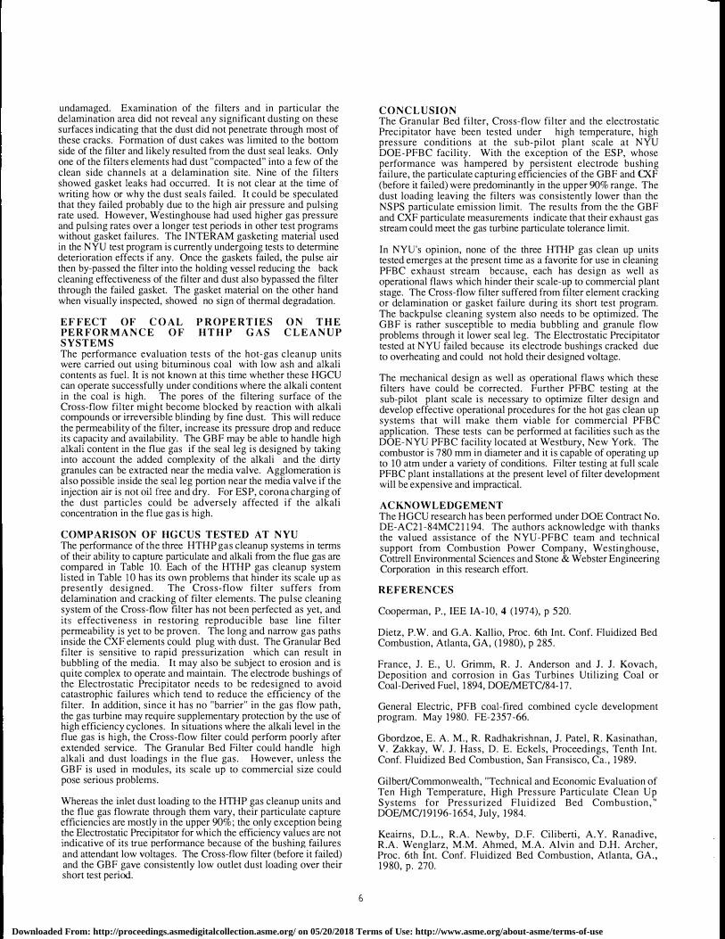
Figure. 4 illustrates the operating principles of the filter element, and Figure 5 shows the schematic flow diagram of the GBF system teste.d at NYU DOE-PFBC facility. Particulate laden gas is mtroduced mto the center of a downward moving bed of 2 or 3 m� alumina granules which act as the cleaning media. The gas 1111t1ally moves concurrently and cross-flow before reversing its dlfect10n upward counter-current to the direction of the movement of t.he media. To prevent the media from fluidizing, the filter is des1¥ned to operate below the minimum fluidization velocity of the me�ia typically, 50% of the �inimum fluidization velocity. Fine particulate m the gas stream 1s collected m the downward moving bed of coarse granules. Clean granules are distributed to the top of the fJ!ter and flow downward through eight equally spaced legs and the annulus formed around the central gas inlet pipe.
From the bottom of the conical section, the ash laden granules are pneumatically conveyed and cleaned in a 50 mm lift pipe. At the top of th� lift pipe, the granules disengage from the lift gas and the fme particles. The clean granules return to the media reservoir from which they are redistributed to the top of the moving bed. The filter media is circulated at a typical rate of between 9 to 27 kg/min using nominally 5 kg/min of transport flue gas. The recycled transport gas with the entrained dust is cooled and then cleaned in a conventional baghouse before the flue gas enters a booster blower which makes up the pressure drop in the lift pipe and the bae:house. Part of the recvcled flue gas is vented to achieve what i
_s known as "pressure balancing". By venting gas
downst_rean: of bo_th the upper and lower seal legs, the pressure in
the enl!re circulat1on system can be maintained slightly less than the pressure in the filter. Under this condition, leakage gas moves down the lower seal leg which enhances flow of the ash and media down the seal leg. The captured dust collected in the pressurized baghouse is removed via a lockhopper system.
PERFORMANCE EVALUATION GBF performance tests were initiated on October 16, 1987. Three shakedown tests and five performance evaluation tests were carri�d out from October 1987 through June 1988. The operating condltlons for the PFBC-GBF tests are presented in Table 5. All but the last test were performed with 2 mm diameter alumina granules as filtration media. In the last test, 3 mm media was used. The shakedown tests were perfom1ed in order to identify and solve subsystem problems, to debug the PFBC-GBF interface system and to fine tune the start up and operating procedures developed for the PFBC-GBF. The performance tests were carried out to evaluate and characterize the performance of the GBF as a high�temperature, hi&h-pressure gas cleaning device for PFBC apphcat10ns and to acqmre data to assess the technical and economic viability of the GBF for commercial PFBC applications.
At the end of the GBF preheat period during the first shakedown test, the_ on-off valve was closed and the by-pass valve was opened m preparation for PFBC start up on coal (see Figure 1). Coal feed was attempted but the coal transport line appeared clogged. The coal feed
_ line was pulsed using high pressure air to
clear the.
1111e. This caused sudden pressurization and depressunzatJon of the PFBC-GBF system. Granules were back-entrained from th
.e
_GBF during the depressurization period
by back flow of gas ex1tmg through the open by-pass valve from the volume created downstream of the GBF by the closed on-off valv�. . A re-occurrence of this situation was prevented by mod1fymg
. the start�up proce�ure originally developed for
Electrostatic Prec1p1tator testmg. Instead of starting coal
Downloaded From: http://proceedings.asmedigitalcollection.asme.org/ on 05/20/2018 Terms of Use: http://www.asme.org/about-asme/terms-of-use

combustion with the filter by-passed, coal was brought on-line with the resultant by-products passing through the granular bed f!lter .. �is turn�d �mt �o be an advantage because I) start-up was simphfi�d by ehmmatmg the need for the by-pass valve and, 2) combustion flue gases were cleaned by passing through the GBF.
In the early part of the testing program, the GBF was operated at gas superficial velocity of about 50% of the minimum fluidization velocity of the granules. During these tests, problems occurred that caused the filter media to bubble. In one test, the PFBC cyclone plugged with ash. To restore operation, high-pressure air was used to remove the pluggage through the cyclone lockhopper below. The media began to bubble and overflow the filter element at this time; consequently, it was suspected by Combustion Power Co. that enough ash was blown out of the cyclone to exceed the capacity of the filter.
The e�trainment. of media out. of the_ filter was minimized by extendmg the skirt of the media holdmg vessel to increase the "free board" above the media. Also, the superficial velocity of flue gas through the filter was reduced from 50% to 25% of the minimum fluidization velocity of the granules in order to alleviate possible media bubbling situations. Filter gas flow was lowered by passing the excess flow through the system by-pass valve. The last three performance tests were run in this fashion. Althou�h there was some concern that a rapid depressurization could mduce backflow of media, this did not occur even at pressure decays exceeding 241 kPa/min. The last three test runs carried out after the modifications were successful at reduced gas flows that were eventually increased to about 35 % of the minimum fluidization of the granules. In the opinion of CPC with the improvements made in the GBF and PFBC, the gas' flow through the GBF coul� �ave been.r�turned to the original designed value of 50% o� the mmimum flmdizanon velocity of the granules had testing contmued beyond the slated test period.
The GBF exp�rienced �edia flow _Problems either in the seal leg from th� media reservoir to the filter proper or in the seal leg connectm? the bottom of the filte'. to the lift pipe. Bridging problems m the seal leg above the filter were solved on-line and were due to refractof)'.' wear as discussed below. Plugging of the seal leg below the filter was more difficult to deal with and resulted in a few shutdowns to clear. The design of the GBF did not make provision for the removal of material at the lower part of the lower seal leg when the system was operating. It was known that con�i�erab�e condensation and some oil was present in the gas used to .mJect drrty granules mto the lift pipe, and by the end of the test senes, it was discovered that line plugging was prevalent in the area local �o the injection of this gas. According to CPC, cond�nsed moisture ongmated from the flue gas and oil was entramed_ from the boost blower lube system. Further GBF modifications and tests would be required to solve this problem.
After the first performance test, �ome sect!ons of the lift pipe were found to show considerable erosion of their refractory lining. The ty�e of refractory used was A. P. Green.Lo-Abrade with back-up lmmg of A. P. Green castable block mix. In the worst eroded sections, the inner diameter of the 50 mm pipe increased by about 50%. Three of the eroded sect10ns were relined with stainless steel and another two were relined with silicon carbide. The five re�aining sections retained the original refractory lining. The pipm� between the GBF media reservoir and the filter vessel also expenenced locally high refractory erosion. A stainless steel liner with a conical section at the top was inserted into the piping to protect the refractory walls of the pipe. The extremely rapid wear of refractory in some sections indicates a refractory quality control problem during or just subsequent to refractory installation. But, even at its best, the lift pipe refractory was scoured and grooved and may have been judged unsatisfactory at the conclusion of the test. Inspection of the lift pipe sections relined with either stainless steel or silicon carbide after the test program, showed no significant erosion.
4
The dust loading into and out of the GBF during a typical run is pr�s�nted in Table 6 for Test # HG 204. The dust capturing efficiency of the GBF appears to depend on the inlet dust loading and increased as the inlet dust loading increased as shown in Figure 6. The outlet dust loading during the test was well below the NSPS limit of 13 mg/MJ (see Table 6).
The average particle size distribution at the inlet and outlet of the GBF for Test # HG-204 is presented in Figure 7. The data presented in Figure 7 were obtained from isokinetic sampling of the flue gas at the inlet and outlet of the GBF using Washington University's Cascade Impactor design and analyzed using a computer program developed by Washington University. The results show that the outlet dust is an order of magnitude finer than the inlet dust. Particle collection efficiency is plotted in Figure 8 as the grade efficiency versus particle size. The figure shows how the GBF was able to collect very small particles (less than 2 µm ) with high efficiency. The GBF grade efficiency tended to increase with particle size up to 6 µm, beyond which, the grade efficiency drops slightly at large particle sizes. The grade efficiency curve for test HG 205 also showed a similar trend.
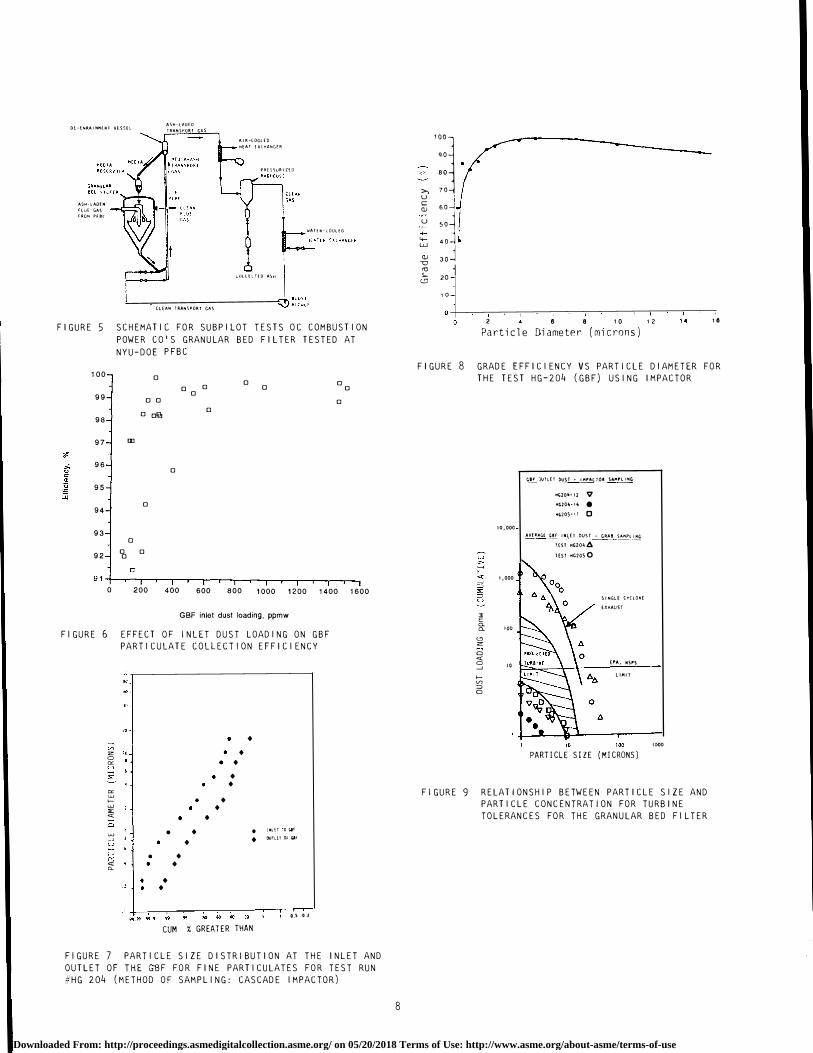
The specification for permissible dust loading to the gas turbines varies from manufacturer to manufacturer. A "recent" projected turbine tolerance limit for particulate matter is shown in Figure 9 (METC, 1985) as a plot of cumulative dust loading versus particle size. Also plotted on Figure 9 are the GBF inlet and outlet cumulative dust loadings obtained from grab and cascade impactor measurements. The projected turbine tolerance band is also shown in the figure. The cumulative outlet dust loading out of the GBF falls below the projected turbine tolerance band suggesting that the dust loading out of the GBF will meet the projected turbine limit and more important, it is fine in grain and can thus be tolerated by the gas turbine. In addition to capturing dust from the PFBC flue gas streams, the GBF also captured alkali compounds in the gas stream with 81 to 99.5% efficiency. For a detailed discussion of the GBF alkali capturing characteristics see Gbordzoe et al. (1989).
The dust leaving the PFBC passes through a single cyclone before it enters the GBF. The cumulative dust distribution at the GBF inlet plotted in Figure 9 clusters around the projected line for single stage cyclone exhaust dust.
In the present design of the GBF, the flue gas is distributed through a central pipe which in the opinion of NYU, is vulnerable to channelling blow-through (spouting) of the filter bed caused by a dust puff upset. Since filtration of dust takes place through the layer of dust cake formed in the vicinity of the gas inlet pipe, in NYU's opinion, the effectiveness of filtration could be increased if �he gas is distributed through several legs as shown in Figure 10 mstead of through a central pipe as in the original CPC design (see Figure 4). The gas will therefore be distributed more effectively across the cross-section of the filter bed. As a result, susceptibility to channelling of the bed will be reduced. The number of gas injection point� can be selected in a manner that will optimize the area covered by each inlet pipe. The spacing between the pipes should be greater than the width of the jet discharged from the pipes. When the jets interfere with each other (because they are in close proximity), the effectiveness of the GBF as a filtration device may be reduced because the flue gas may not be uniformly distributed across the filter bed. This arrangement will increase the effective utilization of the filter bed while preventing local spouting due to macro disturbances in the dust layer and the bed itself. Also, "settling chambers" on the inlet and outlet lines could be provided either upstream or downstream of the GBF to catch entrained media when media spouting occurs.
Due to a lack of instrumentation in the GBF filter bed in the NYU tests, it was not possible to determine gas flow distribution and the fraction of filter volume utilized for filtration inside the media bed. Scale-up of the GBF would be aided by such information. NYU
Downloaded From: http://proceedings.asmedigitalcollection.asme.org/ on 05/20/2018 Terms of Use: http://www.asme.org/about-asme/terms-of-use

recommends that gas flow patterns and dust distribution inside the filter be measured during testing period in future development efforts toward this end. The lift pipe, seal leg and other inter-connecting piping could be lined with a better abrasive resistance refractory material than that used in the NYU test or other suitable materials for example, silicon carbide or hard alumina refractory tubes to reduce the erosive action of the media granules and improve media flow.
3 WESTINGHOUSE CERA M IC CROSS-FLOW FILTER (CXF) The Cross-flow Filter (CXF) is currently under development by Westinghouse for DOE for application in both coal gasification and PFBC combined power generation. The CXF concept is illustrated in Figure 11. The individual filter element blocks are comprised of multiple layers of thin, porous ceramic sheets that have parallel grooves formed on one side. Consecutive layers are oriented, such that, the inlet and outlet channels formed are at right angles to each other. One end of the CXF element is sealed and the opposite end is mounted in a fixture that mechanically supports the element and ducts the filtered gas to a common plenum.
The dirty flue gas enters the CXF through the openings of the channels on the two sides perpendicular to the sealed end. The gas then permeates through the porous ceramic sheets (i.e., the floor and the roof of the channel) and passes through the flow channels that are 900 to the inlet channels. The filtered gas exits downward through the side that is affixed to the support mount. The CXF elements are periodically backpulsed with air to remove the accumulated dust.
PERFORMANCE EVALUATION The major mechanical problem facing the CXF is its tendency to crack or delaminate during high temperature service. This is not catastrophic but could lead to reduction in the filter perfornrnnce. The short term testing at Westinghouse and KRW on the other hand appears to indicate that delamination cracks do not necessarily result in significant dust penetration particularly after the filter mounting was modified. Long term operational effects of the delamination or cracking on filter performance are yet to be demonstrated. Attempts have been made recently to solve the delamination problem by reconfiguring the mid-rib support to permit bonding at the center and allowing corner radius to be effectively utilized.
An earlier rectangular 152.4 x 152.4 x 50.8 mm CXF filter design was tested using one element at a time in a 250 hour test program conducted with the DOE-METC bench scale coal gasifier at Westinghouse. Two out of three of the redesigned CXF elements still experienced cracking and delamination. Westinghouse also carried out several tests of single 305 x 305x 102 mm filter element of the rectangular design type at the Westinghouse HTHP test facility. The improved mid-rib design was first tested at the Westinghouse R & D HTHP facility. The mid-rib design was subsequently utilized in an 8 element filter unit test at the sub-pilot scale PFBC simulator facility located at the Westinghouse Waltz Mill test site. A larger scale PFBC testing of the CXF has been completed at the NYU DOE PFBC facility. The CXF unit tested comprised of fifteen (15) 305 x 305 x 102 mm filter elements mounted in groups of three to form five filter modules. The modules were housed in an existing 2.6 m diameter refractory lined vessel. A schematic diagram of the NYU module is shown in Figure 12. Three of the filter elements used in the NYU test program were previously tested in the Waltz Mill PFBC simulator facility.
Two filter performance tests were carried out with the Cross-flow filter. The first performance test which began on October 4, 1988, was 50 hours in duration. The second performance test was started on October 31, 1988. This test was prematurely terminated to prevent further damage to the filter eleme1_1ts when the fi�ter outlet dust loading obtained from particulate sampling
5
consistently increased with time. A summary of the test conditions is presented in Table 7.
The dust loading into and out of the filter are presented in Table 8 for the first performance test, HX 301. The average flue gas flow through the filter was maintained at approximately 2200 kg/hr (which represents one-third of the total flow out of the PFBC) for a filter face velocity of approximately 0.023 m/s. The excess flow out of the PFBC was routed through the by-pass line (see Figure 1). The filter outlet dust loading remained consistently low, between 2 and 9 ppmw. The particulate collection efficiency of the CXF also depended on the inlet dust loading; being low at low dust loading and high at high dust loading similar to the trend observed for the GBF. The filter was periodically backpulsed with compressed air set between 14 and 16 atm. The pulse frequency was varied but it depended on '.he pressure dr?P across the filter, typically on 30 minute cycle with pulse duration of 0. 3 seconds. The temperature and pressure drop across the filter were approximately 16 oc and between 635 and 980 mm H20
respectively.
Post-test fiberscope inspection of the filter elements revealed that one of the filter elements located at the lower end of the filter assembly had failed and dust trail was observed from a f�w of the channels in one area on the clean side of the filter md1catmg a crack or delamination had occurred. 1bis filter element was not replaced but was blocked off and was not put in operation during the second performance test.
The dust loading into and out of the CXF during the second performance test, HX 302, are present�d in Table
_ 9. The gas
flowrate through the filter was approximately twice that used during the first test with a filter face velocity of approximately 0.045 m/s. As the test progressed, the filter outlet dust loading increased rather slowly with time. Eighteen hours into the test, the system was temporarily shut down to repair three out of the five solenoid blow-back valves for the CXF. The solen01d valves controlled the pulse air flow. Each valve fed one module comprised of three filter elements. When the three valves failed, 9 out of the 15 filter elements could not be effectively cleaned. The plunger assembly stem stop nuts were comple
_tely loosened in two
solenoid valves, and partially loosened m a third one; the stem nut of another valve seized up while the internals of the fifth one partially seized up. The valves were dismantled, cleaned and re-installed. No further valve problems occurred afterwards. Shortly after this, there was another temporary shut down of the facility to repair a PFBC charcoal feed lock hopper knife-gate valve seal that failed. The bed was not drained and restart was attempted with a rather deep bed. The standard practice is to drain the bed to a low bed depth before restart is attempted. During the restart process, the filter inlet temperature reached as high as 10270 C and the filter flange temperature exceeded 870° C, indicating post combustion in the freeboard of the PFBC due to entrainment of fine coal particles from the bed.
The filter outlet dust loading prior to the knife-gate valve failure was about 32 ppmw indicating that the filter was experiencing problems prior to the failure of the PFBC knife-gate valve seal. After the restart of the bed, successive outlet dust measurements showed increase in the dust loading out of the filter ( see Table 9). The test was prematurely terminated to identify possible problems and prevent further _damage to the filter �he1_1 the outlet dust loading increased steadily to 105 ppmw mdicatmg that a significant leak through the filter system had occurred.
At the end of the second perfonnance test, the filter was again inspected with fiberscope and dust was observe
_d on the clean side
of 3 of the five filter banks. The Cross-flow filter assembly was subsequently removed from its holding vessel and inspected. Five of the fourteen active filter elements (a filter element was blocked off after the first performance test) had either (or both) small flange or delamination cracks. Ten of the filters were basically
Downloaded From: http://proceedings.asmedigitalcollection.asme.org/ on 05/20/2018 Terms of Use: http://www.asme.org/about-asme/terms-of-use
undamaged. Examination of the filters and in particular the delamination area did not reveal any significant dusting on these surfaces indicating that the dust did not penetrate through most of these cracks. Formation of dust cakes was limited to the bottom side of the filter and likely resulted from the dust seal leaks. Only one of the filters elements had dust "compacted" into a few of the clean side channels at a delamination site. Nine of the filters showed gasket leaks had occurred. It is not clear at the time of writing how or why the dust seals failed. It could be speculated that they failed probably due to the high air pressure and pulsing rate used. However, Westinghouse had used higher gas pressure and pulsing rates over a longer test periods in other test programs without gasket failures. The INTERAM gasketing material used in the NYU test program is currently undergoing tests to determine deterioration effects if any. Once the gaskets failed, the pulse air then by-passed the filter into the holding vessel reducing the back cleaning effectiveness of the filter and dust also bypassed the filter through the failed gasket. The gasket material on the other hand when visually inspected, showed no sign of thermal degradation.
EFFECT OF COAL PROPERTIES ON THE PERFORMANCE OF HTHP GAS CLEANUP SYSTEMS The performance evaluation tests of the hot-gas cleanup units were carried out using bituminous coal with low ash and alkali contents as fuel. It is not known at this time whether these HGCU can operate successfully under conditions where the alkali content in the coal is high. The pores of the filtering surface of the Cross-flow filter might become blocked by reaction with alkali compounds or irreversible blinding by fine dust. This will reduce the permeability of the filter, increase its pressure drop and reduce its capacity and availability. The GBF may be able to handle high alkali content in the flue gas if the seal leg is designed by taking into account the added complexity of the alkali and the dirty granules can be extracted near the media valve. Agglomeration is also possible inside the seal leg portion near the media valve if the injection air is not oil free and dry. For ESP, corona charging of the dust particles could be adversely affected if the alkali concentration in the flue gas is high.
COMPARISON OF HGCUS TESTED AT NYU The performance of the three HTHP gas cleanup systems in terms of their ability to capture particulate and alkali from the flue gas are compared in Table 10. Each of the HTHP gas cleanup system listed in Table 10 has its own problems that hinder its scale up as presently designed. The Cross-flow filter suffers from delamination and cracking of filter elements. The pulse cleaning system of the Cross-flow filter has not been perfected as yet, and its effectiveness in restoring reproducible base line filter permeability is yet to be proven. The long and narrow gas paths inside the CXF elements could plug with dust. The Granular Bed filter is sensitive to rapid pressurization which can result in bubbling of the media. It may also be subject to erosion and is quite complex to operate and maintain. The electrode bushings of the Electrostatic Precipitator needs to be redesigned to avoid catastrophic failures which tend to reduce the efficiency of the filter. In addition, since it has no "barrier" in the gas flow path, the gas turbine may require supplementary protection by the use of high efficiency cyclones. In situations where the alkali level in the flue gas is high, the Cross-flow filter could perform poorly after extended service. The Granular Bed Filter could handle high alkali and dust loadings in the flue gas. However, unless the GBF is used in modules, its scale up to commercial size could pose serious problems.
Whereas the inlet dust loading to the HTHP gas cleanup units and the flue gas flowrate through them vary, their particulate capture efficiencies are mostly in the upper 90%; the only exception being the Electrostatic Precipitator for which the efficiency values are not indicative of its true performance because of the bushing failures and attendant low voltages. The Cross-flow filter (before it failed) and the GBF gave consistently low outlet dust loading over their short test period.
6
CONCLUSION The Granular Bed filter, Cross-flow filter and the electrostatic Precipitator have been tested under high temperature, high pressure conditions at the sub-pilot plant scale at NYU DOE-PFBC facility. With the exception of the ESP, whose performance was hampered by persistent electrode bushing failure, the particulate capturing efficiencies of the GBF and CXF (before it failed) were predominantly in the upper 90% range. The dust loading leaving the filters was consistently lower than the NSPS particulate emission limit. The results from the the GBF and CXF particulate measurements indicate that their exhaust gas stream could meet the gas turbine particulate tolerance limit.
In NYU's opinion, none of the three HTHP gas clean up units tested emerges at the present time as a favorite for use in cleaning PFBC exhaust stream because, each has design as well as operational flaws which hinder their scale-up to commercial pl
_ant
stage. The Cross-flow filter suffered from filter element cracking or delamination or gasket failure during its short test program. The backpulse cleaning system also needs to be optimized. The GBF is rather susceptible to media bubbling and granule flow problems through it lower seal leg. The Electrostatic Precipitator tested at NYU failed because its electrode bushings cracked due to overheating and could not hold their designed voltage.
The mechanical design as well as operational flaws which these filters have could be corrected. Further PFBC testing at the sub-pilot plant scale is necessary to optimize filter design and develop effective operational procedures for the hot gas clean up systems that will make them viable for commercial PFBC application. These tests can be performed at facilities such as the DOE-NYU PFBC facility located at Westbury, New York. The combustor is 780 mm in diameter and it is capable of operating up to 10 atm under a variety of conditions. Filter testing at full scale PFBC plant installations at the present level of filter development will be expensive and impractical.
ACKNOWLEDGEMENT The HGCU research has been performed under DOE Contract No. DE-AC21-84MC21194. The authors acknowledge with thanks the valued assistance of the NYU-PFBC team and technical support from Combustion Power Company, Westinghouse, Cottrell Environmental Sciences and Stone & Webster Engineering Corporation in this research effort.
REFERENCES
Cooperman, P., IEE IA-10, 4 (1974), p 520.
Dietz, P.W. and G.A. Kallio, Proc. 6th Int. Conf. Fluidized Bed Combustion, Atlanta, GA, (1980), p 285.
France, J. E., U. Grimm, R. J. Anderson and J. J. Kovach, Deposition and corrosion in Gas Turbines Utilizing Coal or Coal-Derived Fuel, 1894, DOE/METC/84-17.
General Electric, PFB coal-fired combined cycle development program. May 1980. FE-2357-66.
Gbordzoe, E. A. M., R. Radhakrishnan, J. Patel, R. Kasinathan, V. Zakkay, W. J. Hass, D. E. Eckels, Proceedings, Tenth Int. Conf. Fluidized Bed Combustion, San Fransisco, Ca., 1989.
Gilbert/Commonwealth, "Technical and Economic Evaluation of Ten High Temperature, High Pressure Particulate Clean Up Systems for Pressurized Fluidized Bed Combustion," DOE/MC/19196-1654, July, 1984.
Keairns, D.L., R.A. Newby, D.F. Ciliberti, A.Y. Ranadive, R.A. Wenglarz, M.M. Ahmed, M.A. Alvin and D.H. Archer, Proc. 6th Int. Conf. Fluidized Bed Combustion, Atlanta, GA., 1980, p. 270.
Downloaded From: http://proceedings.asmedigitalcollection.asme.org/ on 05/20/2018 Terms of Use: http://www.asme.org/about-asme/terms-of-use

Lippert, T.E., D.F. Ciliberti and S.G. Drenker, EPRI Second Biennial Pressurized Fluidized Bed Combustion Power Plant Utility Conference, Milwaukee, WI., June 18-20, 1986.
METC, "Physical Gas Clean Up Technology Status Report", DOE/METC-86/0239, March, 1985.
Robinson, M., "Electrostatic Precipitation, In Air Pollution". W. Strauss Ed. Vol 1, John Wiley, NY, 1971.
Rubow, L.N., Proceedings 3rd Int. Fluidized Conference, London, England, Oct., 1984.
Scandrett, L. A. and R. Clift, The Thermodynamics of Alkali Removal from Coal-Derived Gases, J. Inst. Energy, 1984, 57, 391-397.
Schiffer, H. P., U. Renz, O.J. Tassicker and E. K. Reinhardt, Proc. 9th Int. Conf. Fluidized Bed Combustion, Boston, Mass. (1987),p.1000.
Zakkay, V., K.M. Sellakumar, R.J. Dellefield and S.J. Bossart, 1988 EPRI Seminar on Fluidized Bed Combustion Technology for Utility Applications, Palo Alto, CA., May 3-5, 1988.
Zakkay, V., et al, Construction and Utilization of a Large Scale Coal-Fired PFB Facility, Fossil Energy, Report No. DOE/MC/14322-1800 (DE 850136850), August, 1985.
FIGURE l SCHEMATIC OF DIAGRAM OF NYU-DOE PFBC/GBF SYSTEM SHOWING INLET AND OUTLET SAMPLING STATIONS
FIGURE 2 SCHEMATIC OF THE HTHP ESP
7
'00 -r-------------------r '°
- 20 VJ z 0 0:: u "
0:: w fw :;;::: "1: � 2 Cl w _J u l,D
f-0:: ,, "1: CL
• • • •
• • • •
• • • •
•• ..
• ..
.. ..
.. ..
•• ..
.. ..
•• ••
••
• INLET 10 ESP
• OUTLET C� ESP
0 '-+----.-�-�-...--.---.-...--...---.--r-T--1 99 99 99 9 99 9S So 6C �c 2 .OS O
C�M. % GREATER THAN
FIGURE 3 PARTICLE SIZE DISTRIBUTION ENTERING AND LEAVING ESP FOR TEST RUN HE 101
CJL!-i'EK fLO'ol COLLf:,'IONl:JNE
' DIRTY MEDIA �E'IOVAL
�IGURE 4 COMBUSTION POWER COMPANY'S GRANULAR BED FILTER ELEMENT
Downloaded From: http://proceedings.asmedigitalcollection.asme.org/ on 05/20/2018 Terms of Use: http://www.asme.org/about-asme/terms-of-use
DE-E'IRAINJ'\UO VESSEL
ASH-LAOH�
FU>E GAS
�ROH PF er
A'iH-L.aOfO
TRA'ISPORI GAS
AIR-LDOLfO
HEAT EXCHA'IGER
PRtS')LJRIHO
'.IAlfk-LOOUO
L!JlllLHO AS11
CLEAN lRA'ISPORT GAS
FIGURE 5 SCHEMATIC FOR SUBPILOT TESTS OC COMBUSTION POWER CO'S GRANULAR BED FILTER TESTED AT NYU-DOE PFBC
100 D
99 D D
98 D 0'0
97 "'
96
95
94
93
92
D
D D D D
D
D D D
D
D D D D D
0 200 400 600 800 1000 1200 1400 1600
GBF inlet dust loading, ppmw
FIGURE 6 EFFECT OF INLET DUST LOADING ON GBF PARTICULATE COLLECTION EFFICIENCY
• VO z '" • 0 . "" • '-' "' •
• "" w >--- • w • "' "" •
w • • • JNl£T;QQf
_, • • l)JfLEl 01 &a� '-' >--- • "" � •
• •
"" l o.� o .2
CUM % GREATER THAN
FIGURE 7 PARTICLE SIZE DISTRIBUTION AT THE INLET AND OUTLET OF THE GilF FOR FINE PARTICULATES FOR TEST RUN #HG 204 (METHOD OF SAMPLING: CASCADE IMPACTOR)
8
'"'l
qo
,')'-'..; 80
>, 70 u i c 60 __j QJ u 50] 4-
4- 40 w
30j QJ -0 "'
20 l ,_
(.!) 1 0
2 6 8 10 12 16 Particle Diameter (microns)
FIGURE 8 GRADE EFFICIENCY VS PARTICLE DIAMETER FOR THE TEST HG-204 (GBF) USING IMPACTOR
� E 0. 0. '-" z 0 "" 0 _, >-VO ::::> 0
10,000
l,000
lOO
lO
1ar JUILEI ousr - IJ'\PAOO� SAJ'\PLl'IG
Ml.i20"·l2 V liG20-·1li • HG205·1! 0
AVfOGC Gar INLET OUST - GRAB SAAPllllG
HST MG20�A -- -
TEST HG20S0
lO
SINGLE CY(LONE
EXHAUST
£PA, NSPS
LIMIT
100 PARTICLE SIZE (MICRONS)
10-00
FIGURE 9 RELATIONSHIP BETWEEN PARTICLE SIZE AND PARTICLE CONCENTRATION FOR TURBINE TOLERANCES FOR THE GRANULAR BED FILTER
Downloaded From: http://proceedings.asmedigitalcollection.asme.org/ on 05/20/2018 Terms of Use: http://www.asme.org/about-asme/terms-of-use

Flue Gas
FIGURE 10 GBF WITH MULTIPLE GAS INLET DUCT
( b) Improved Element showing "mid-rib bond" Design
FIGURE 11 SCHEMATIC REPRESENTATION OF THE CROSS-FLOW FILTER
9
r .-- !iow·O•Cl p�pe
,_..,.- 81 o.i- O.ic k �tiDPor� use�ly
Filter module venturi
Fh11•19•d cross-flow f11t•rs
FIGURE 12 SCHEMATIC OF CROSS FLOW FILTER
Downloaded From: http://proceedings.asmedigitalcollection.asme.org/ on 05/20/2018 Terms of Use: http://www.asme.org/about-asme/terms-of-use

TABLE I
SUMMARY Of HOT GAS PARTICULATE REMOVAL TECHNOLOGY
Device Col lectlon Operat1ng Capaclty Efficiency 11 P - mbar ACMS/m2
Cy Jones • Conv�nt1onal Low {• 90'1) 75 to 112
o Elect.Hied Low ( ,901) 75 to 112
Granular Fi 1 ters
o fhed Shallow Good ( , 99t) 40 to 80 bed ( Ducon/W/ DOE)
-730
• CPC-Screenless Good ( ,991) 60 to 100 1100 ( CPC/OOE)
ESP (CES/OOE) Good ( ' 99t) 3 to 6
Ceram1c Bag Filters
. Felted (Batted) 20 to SO (A/A/00£/�/- High ( • 99. St) EPRI)
• Woven High ( 99. St) 12 to 35
Rigld Filters
so
200
100
• Ceramic Candle E11cellent ( '99. 9t) SO to 100 20D
• Cross Flow Excellent (�/DOE) ( ·99.9t)
Abbreviations:
15 to 30 300
ACMS Actual cubic meters per second G£ General Electric Company DOE U.S. Department of Energy W Westinghouse Electric Corporation (P Combustion Power Co. CES Cottrell £ny1ronmental Sciences ESP Electrostatic Precip1tator A/A Accurex Corporation NYU New York University C.W. Curtiss Wright
Major Issues for PFBC
• Requ1 res stack gas
• ��l��t��,�� ... 1�� Turbine L He
• Same as Above
• Bed Bl 1nd1ng -Ineffective Cleaning 1n Large Array
Development Status 1988
t Conwnercial
1 Electrical malfunctions in HTHP Testing; work discontinued.
• Additional Development Needed for HTHP Oesign-DOt Funding 01scont1nued
• Comple.x1ty/Rel1ab1lity •
of Media Transport System
Low Temperature. Low Pressure Corrrnerc1al Systems Operational
• Sensitive to rapid pressure fluctuations
e HTHP Subpilot Unit Tested at NYU
• Durability of Electri- • Subpilot Unit at C.W. cal Components Damaged Due to Process
• Sustaining Performance Upsets in HTHP Environment • HTHP Subpilot Unit Tested at
1 Cleaning by Rapping NYU. Work discontinued due to • Electrode Bushings failed electrical bushings
Design
• Felt Durability • Blinding
• Fabric Ourabi 1 ity
• Problems w1 th Candle Support Sys terns
• Blinding Mount 1 ng Candh Durability
• Mounting • Cleaning 1n Multi
Element Array • Cl 0991 ng of
Filter • Filter Delamination
and Cracking
• HTHP Subpi lot Test at '.I and C.W. Show lnab1l1tY to clean
• Development of Seamless Bag Configuration
• Successfully Tested at HTHP 1n Single Bag Rig
• HTHP Bench Seale Testing over 2000 Cyc l es
• Large Candle Array lesteO at Grimethorpe
1 HTHP 100 Hr. Test Completed on ANL-PFBC Single Element
• HTHP Subp1lot Test Col'flpleted at NYU on 305 X 305 X 102 rrrn
Fi 1 ter Elements
TABLE 2; PFBC-ESP OPERATING DATA
Run Test Da!e
Number Start
�NI.� HS 101 10 29·86
End
11 -1-86
e�BEQBMAN�f; If.s.IS HE 101 11-18 86 1 1 - , 9-86
HE 102 3 · 1 -81 3-13·87
Includes !liter pre�1eat period
Average Bed
Pressure (atma)
8 5
8 6
9 . 1
Average Filter Temp, C Ourat1on of Opera!1on Inlet Outlet with Kerosene
Pre heat combustor'
(hi)
849 7 1 6 12 0
859 694 17 2
8'7 655 ,, 5
@ Excludes the period PFBC lower p1enum start up kerosene combustor was on
l 0
Durat1onof
PFBC Operation on coal@
(hr)
46 0
21 1
24 5
Downloaded From: http://proceedings.asmedigitalcollection.asme.org/ on 05/20/2018 Terms of Use: http://www.asme.org/about-asme/terms-of-use

TABLE 3 PERFORMANCE CHARACTERISTICS OF ESP TESTED AT NYU
(FIRST PERFORMANCE TEST)
Aun No Bed Pressure Gas Flow Fiiter Temperature Filter Dust Collection atma Into Filter (Deg C) Loading (ppmw) Eff1c1ency
ESP Electrode Voltage (kV)
10 1 - 1 8 . 4
1 0 1 ·2 8 . 7
1 0 1 - 3 8 7
1 0 1 4 8 7
1 0 1 5 8 6
1 0 1 6 8 6
(kg/hr) % I n l e t Outlet
671 7 81 2 6 3 6
6880 865 674
6939 852 6 92
6957 876 7 19
6896 8 7 1 7 2 2
0892 8 7 5 722
In let Outlet
4 6 7 6 1 5 5 7
6 0 4 3 1 9 6 5
5 4 02 1 2 0 9
5 0 7 4 1268
5 6 6 6 1 122
4 9 9 8 1 4 4 0
6 6 8
67 5
77 6
7 6 2
80 2
71 2
·second electrode was electrically grounded alter Run # 1 0 1 · 1
TABLE 4
PERFORMANCE CHARACTERISTICS OF ESP TESTED AT NYU (SECOND PERFORMANCE TEST)
Seoond Electrode Electrode"
4 0 4 0
4 0
4 0
3 8
3 8
Run No Bed �}-r�;s��e-- - G-a� -
F-1o
_w
_ ---F 1l1;;-r-;�p;;a1u-;; --F1�6r-D�St--- - - - -C011-;ci�o�---- -E-sP-E1;ct;Qd;- - -------
atrnd into F i l te r (Deg CJ Loading (ppmw) Efl 1c 1ency Voltage (kV)
1 02 - 1 8 1
102-2 9 3
9 0
1 0 2 4 9 5
9 0
1 02 · 6 8 8
{ k g / h r ) % l n l e t
79 2 1 6 6 0
7 4 0 9 8 8 5
7 12 6 7 8 0
6672 8 4 6
7072 8 6 9
6 8 8 3 8 64
Outlet
4 9 1
6 72
5 9 5
7 0 1
732
7 3 6
Inlet Outlet
499 120
6388 9 8 7
5 3 4 5 2 8 5 0
9 2 7 5 2 6 1 '
7 4 0 8 2216
7786 1739
TABLE 5: PFBC-GBF OPERATING DATA
76 0
84 6
46 7
71 8
70 1
7 7 l
First Serond Electrode Electrode
0 1 1 0 1 1
4 0 8 0
0 1 1 0 1 1
0 1 1 3 8
0 1 1 3 7
32 3 6
Run Test Date Average Average Filter Temp , C Duration of Operation Durat1onot
Number Start
HS ?01 1 0 - 1 6 - 8 1
HS 2C2 1 0 - 2 8 8 1
HS 203 2 - 1 8 88
Erd Bed
Pressure
( a t m a )
1 0 1 6 - 8 7 4 9
1 0 -2 9 · 8 7 5.9
2-19-88 6 8
f�BE�B.MANJ;E IJaLS HG 201 1 1 - 3 8 7
HG 202 3 · 1 88
HG 203 4 1 2 - 8 8
H G 204 5-9 88 HG 205 6·6 tH.3
1 1 - 4 - 8 7 6 7
3-3-88 4 . 6
4 - 1 5 - 8 8 6 9
5 - 1 3 - 8 8 8 8
6-9-86 9 0
Includes filter preheat period
Inlet
51 7
7 7 2
7 6 6
5 6 8
6 3 4
823
6 4 4
842
Outlet
3 8 1
6 0 3
6 0 0
4 6 9
529
682
6 7 6
7 3 8
with Kerosene
Pre-heat combustor·
lhr)
9 62
1 6 . 1
1 3 . 5
28 4
2 1 . 9
1 3
10 9
14 2
@ Excludes theper1od PFBC lower ptenum start up kerosene combustor was on
PFBC Operation
on coal@
(hr)
Nona
None
4 6
3 0
13.3
42 7
74 2
47 2
l l
Table Dust loadlng Into and out of the GBF, THt HG·204 Grab Sampllng
GBF Inlet Oust GBF Outlet Dust
Flue Gas FIOYI Concentration Concentration Efficiency Run No. 1n to GBF
Kg/hr ppmw mg/MJ ppmw mg/MJ '
?04-G 1 2541 1457.0 478.7 16.07 5.2 98.9
204-G2 2877 623.1 230.1 9.55 3.5 98.5
204-G3 3033 118.8 45.1 3.44 1 .J 97.1
204-G4 3018 78.6 29.0 6.08 2.6 92.2
204-GS 3034 142.6 53 7 12.23 4 8 91.4
204-G6 2998 88.4 32.9 7.10 2.6 92.0
204-Gl 2985 202 75.0 15 7 5.6 92.2
204-G8 31 1 5 1 508 548.6 6.8 2.6 99.5
204-G9 3159 • 457 535 2 4 1 1 1 3 99.7
204-G10 3�77 976.7 363 3 4 57 1 7 99 5
204-G 1 1 3708 1 32 1 53.7 9.6 3 9 92.7
204-G12 3721 310 128.3 5 6 2.6 98 2
204-G13 37'2 596 3 240.1 3 1 1 3 99 5
204-G 1 4 2544 233.5 73.2 13.3 4 3 94.3
204-G15 2522 397.2 147 3 16.8 6.1 95.8
204-G 1 6 3594 232.9 91.0 2.60 0.9 98.9
204-G 1 7 3572 523.8 206.3 4.40 1 . 7 99.2
204-G18 3596 1 32 7 52 0 3.80 1.7 97.1
204-G 1 9 3600 303 2 , 19.6 5.10 2.2 98 3
204-G20 3578 203.4 79.3 3 .49 1 3 98 3
204-G21 3593 272.1 1 07.9 4 90 22 98.2
204-G22 3578 858.1 330 6 2 82 1 3 99.7
204-G23 3580 463 4 1 78 1 2 60 0.9 99.4
204-G24 3537 299 2 1 1 3.5 3 21 1 3 98.9
204-G25 3532 282 1 1 07 0 1 00 0 4 99 9
Note By·Pass '1a ve was 00€'"'
Downloaded From: http://proceedings.asmedigitalcollection.asme.org/ on 05/20/2018 Terms of Use: http://www.asme.org/about-asme/terms-of-use

TABLE 7: PFBC-CXF OPERATING DATA
Run Tes! Date
Number Start
SHAKEQOWN l.ES.I.S
Average
Erd Pressure
( a l m a )
COLD Al TEA SHAKE DOWN TEST ONLY
PERFORMANCE If.llS HX 301 1 0 - 4 - 8 8 1 0 - 7 - 8 8 B 1
HX 302 1 0 - 3 1 - 8 8 1 1 - 2 - 8 8 8 2
Includes filter preheat period
Average Filter Temp., C Duration of Operation
Inlet
6 3 4
7 3 6
Outlet
6 9 4
6 6 6
with Kerosene
Pre-heat combustor·
(hr)
, 3 , 4
@ f)(Cludes the period PFBC lower plenum start up kerosene combustor was on
Durat1onof
PFBC Operation
on coal@
(hr)
5 3
3 ,
Table 8 : Dust loading into and out o f the CXF for Test HX-30l
From Grab Sampling. Filter Face velocity-0.023 mis.
Table 9 . Dust loading in and out of the CXF for Test HX-302
From Grab Sampling. Filter Face velocity- 0.045 mis.
Flue Gas Flo"'
Run No. in to CXF
Kg/hr
301 -X1 2218.0
301 -X2 2 1 99.5
301 - X3 2209.0
301-X4 2154.5
30 1 ·X5 2 1 76.1
301-X6 2213.3
301 -X? 221 1 .5
301 -X8 21 97.6
301 -X9 21 98.5
301 -X10 21 86.3
301 -X1 1 21 67.1
301 -X1 2 21 85.1
301 -X1 3 2 1 80 . 1
30 1 -X 1 4 2 1 84 9
CXF Inlet Dust CXF Outlet Dust Efficiency
Concentration Concentration
CXF Inlet Dust CXF Outlet Dust Flue Gas FIOI'.
Concentration Concentration Run No. into CXF
% ppmw mg/MJ ppmw mg/MJ
k g / h r ppmw mg/MJ ppmw mg/MJ
302-X1 4621 337.2 1 55.6 1 4.46 6.9 1 021 .4 249.8 2.84 0.86 99.7
302-X2 4526 245.5 1 1 3.1 1 0.27 4.7 405.7 1 00.6 3.85 0.86 99.1
302-X3 4555 441 .3 204.7 20.35 9.5 384.3 98.5 5.45 1 .29 98.6
302-X4 4550 347.8 1 62.5 24.24 1 1 .2 499.2 1 25.1 4.89 1 .29 99.0
302-X5 4545 257.4 1 20.0 31 .85 1 5. 1 768 2 1 99.1 6.46 1 .72 99.2
PFBC UPSET OCCURED AT THIS POINT 691 .8 1 78.0 6.80 1 .72 99.0
302-X6 4073 459.1 1 82.7 642.4 1 64.7 5.60 1 .29 99. 1
302-X7 4 1 3 1 599.5 246.4 305.4 77.8 5.52 1 .29 98.2
302-X8 4 1 04 637 3 261.0
486.5 1 23.8 5.23 1 .29 98.9
766.2 1 94.4 5.57 1 .29 99.3
690.7 1 75.5 8.31 2. 1 5 98.8
850.6 2 1 5.9 6.03 1 .72 99.3
425.3 1 07.5 5.54 1 29 98.7
322.5 8 1 7 5.92 1 .72 98.2
TABLE 10 PERFORMANCE COMPARISON OF THE HOT GAS CLEANUP UNITS TESTED AT NYU
(�<aTmg Cond�IOflB
f>,e;s lfll&t Oul"'t
Cross l lvw !I Fi l ler (W•"l'"ll
G•aould• Bad f ,'lnr
!Co"1t>usl1or1
Powe< r.o '"' I
P , &L'l-'•ldh>I IRH'l'ldf' h
F111.,, Ternp T &mp De<-.IC Do:ogC
6.(1:1 5 36 756 6 Q6
Fll!er Dusi loading ppmw Abll l o•d•f>9 ppbw Alkali F- Flll•r (N• • K) ColMctW>g
Through V•loclly l lhc.,ncy F111.,r F iiter Etflc,.ncy F•lltH Kg/hr % %
when l<lter Jailed
1 1 22 1 !1 6 5 "
" " '
AHull>I are nol •Vllllmbi.
1 5 7 • · 8H 7 2 " � H.5
Thu outl<>I dust loddtng 1s high and thtt alf1c1ency low because of electrode bushing la+lures and subsaquent 111ab1hty to hold voltage
1 2
F�et per1urm•nc.e , .... ..,. .uooe..,ul S.oc"'d per1onnan<:• I•.,. .,.• prem.lurel� l•rmlf\Aled d,,.. lo ll!l•r l•1lu•• llll•1 pni,ne 1o d.-r
-..
Te ... lng IUOC.ulull� c:ompleled 1- •nd
....- grenul•• l•ll•d
Thlo ll,.. eo.d .-cond perfounaooe te•ll '"'""' P<•m•lurel� 1•rmio•led tle<:.ll._ or •�•ode
bu&hlng t1Hur1
65.37 25.8
70. 1 1 28.8
1 04.8 43.0
fficiency
%
95.7
95.8
95.4
93.0
87.6
85.8
88.3
83.6
Downloaded From: http://proceedings.asmedigitalcollection.asme.org/ on 05/20/2018 Terms of Use: http://www.asme.org/about-asme/terms-of-use