
Performance of Exterior RC Joints with Different ... of Exterior RC Joints with Different...
8
Performance of Exterior RC Joints with Different Reinforcement Detailing under Cyclic Loading S.Kanaka Durga Research Scholar, Structural Engineering Division Department of Civil Engineering IndianInstitute of Technology Madras Chennai, India [email protected] Dr.G.Appa Rao Professor, Structural Engineering Division Department of Civil Engineering Indian Institute of Technology Madras Chennai, India [email protected] Abstract—Evaluation of seismic performance of reinforced concrete (RC) structures built during the 1950’s through 1970’s designed only for gravity loads is very important. Understanding the behaviour of structural components in such non-seismically designed structures when subjected to earthquake forces through experimental investigation is necessary prior to the application of any retrofitting measure. Beam-column joint in such structures is one of the critical structural sub-assemblage severely damaged due to high shear stresses under earthquake loading. The joints in non-ductile reinforced concrete buildings have the characteristics like anchorage length not extended into the joint core and limited or no confinement of the joint region. The present study deals with the performance of poorly, lightly and ductile detailed exterior jointsdesigned for gravity and seismic loading respectively as per IS 456:2000 and IS 13920:1993 under cyclic loading. To accomplish the objective three exterior beam- column joints were prepared and tested to failure under reversed cyclic loading. All joints are geometrically similar but different in reinforcement detailing, which are designated as poorly, lightly and ductile detailed according to the anchorage length of beam bars and confinement of lateral reinforcement in the joint. The mode of failure, shear strength, energy dissipation capacity and stiffness degradation of joints are important properties investigated. Keywords-beam-column joint; reversed cyclic loading; anchorage length; confinement reinforcement I. INTRODUCTION The design of moment resisting frames in buildings prior to 1970\s lack seismic strength and detailing. The dimensions and reinforcement detailing provided in the non-seismically designed structural system may be adequate for gravity, routine wind and mild earthquake loading but inadequate for strong earthquake forces. The load transfer mechanism has to be effective from one structural member to another. Beam-column joints in reinforced concrete moment resisting frames transfer forces among the framing members. It is important to study the forces developed and mechanism of transfer of forces in the joint to achieve adequate strength and improve the detailing joints. The transfer of resulting forces due to horizontal and vertical forces in the joint region can be possible through diagonal concrete strut in compression. Under earthquake motions, unconfined joints can fail due todebonding of beam bars resulting in extensive diagonal tension cracking in the core region. To avoid such failures, adequate anchorage length of beam bars and transverse reinforcement should be ensured. This helps in improved energy dissipation and ductility. II. BACKGROUND Many researchers have performed analytical modelling and experimental investigations on reinforced concrete beam- column jointsunder monotonic and cyclic loading to understand the behavior and shear strength by varyinginfluencing parameters. Broadly, the studies were performed on exterior connections, interior connections and knee connections. Analytical models have been developed using strut-and-tie method, force equilibrium, strain compatibility and constitutive laws of cracked reinforced concrete. In [1] considered simple laws of statics and developed equations for internal forces in interior beam-to- column joint. The effects of several critical design parameters on the joint behaviour were explored by developing finite element model, analytical models and experimental studies. Further the implications of the results on the existing code specifications were discussed in many research attempts. In [2] proposed softened strut-and-tie model for determining the shear strength of exterior beam-column joints under seismic loading. Using the proposed strut-and-tie model [3] designed exterior beam- column joints and tested under cyclic loading to study the effect of amount and detailing of confinement reinforcement. A parametric study [4] reported to determine the shear capacity of beam-to-column connections. A model was developed to account for different parameters influencing the shear strength of beam-column connections and to predict the ultimate shear capacity more accurately than that of the current models. The parameters include; (i) detailing and anchorage of beam reinforcement, (ii) stirrup reinforcement ratio within the joint, (iii) column reinforcement, (iv) joint slenderness. III. ANCHORAGE LENGTH AND TRANSVERSE REINFORCEMENT The stiffness in the exterior beam-column joints was reduced [5] due to slippage of column longitudinal reinforcement and pullout of the beam longitudinal reinforcement from the joint. They suggested that limited amount of joint transverse reinforcement can be provided when
Transcript of Performance of Exterior RC Joints with Different ... of Exterior RC Joints with Different...

Performance of Exterior RC Joints with Different
Reinforcement Detailing under Cyclic Loading
S.Kanaka Durga
Research Scholar, Structural Engineering Division
Department of Civil Engineering
IndianInstitute of Technology Madras
Chennai, India
Dr.G.Appa Rao
Professor, Structural Engineering Division
Department of Civil Engineering
Indian Institute of Technology Madras
Chennai, India
Abstract—Evaluation of seismic performance of reinforced
concrete (RC) structures built during the 1950’s through 1970’s
designed only for gravity loads is very important. Understanding
the behaviour of structural components in such non-seismically
designed structures when subjected to earthquake forces through
experimental investigation is necessary prior to the application of
any retrofitting measure. Beam-column joint in such structures is
one of the critical structural sub-assemblage severely damaged
due to high shear stresses under earthquake loading. The joints
in non-ductile reinforced concrete buildings have the
characteristics like anchorage length not extended into the joint
core and limited or no confinement of the joint region. The
present study deals with the performance of poorly, lightly and
ductile detailed exterior jointsdesigned for gravity and seismic
loading respectively as per IS 456:2000 and IS 13920:1993 under
cyclic loading. To accomplish the objective three exterior beam-
column joints were prepared and tested to failure under reversed
cyclic loading. All joints are geometrically similar but different in
reinforcement detailing, which are designated as poorly, lightly
and ductile detailed according to the anchorage length of beam
bars and confinement of lateral reinforcement in the joint. The
mode of failure, shear strength, energy dissipation capacity and
stiffness degradation of joints are important properties
investigated.
Keywords-beam-column joint; reversed cyclic loading;
anchorage length; confinement reinforcement
I. INTRODUCTION
The design of moment resisting frames in buildings prior to 1970\s lack seismic strength and detailing. The dimensions and reinforcement detailing provided in the non-seismically designed structural system may be adequate for gravity, routine wind and mild earthquake loading but inadequate for strong earthquake forces. The load transfer mechanism has to be effective from one structural member to another. Beam-column joints in reinforced concrete moment resisting frames transfer forces among the framing members. It is important to study the forces developed and mechanism of transfer of forces in the joint to achieve adequate strength and improve the detailing joints. The transfer of resulting forces due to horizontal and vertical forces in the joint region can be possible through diagonal concrete strut in compression. Under earthquake motions, unconfined joints can fail due todebonding of beam bars resulting in extensive diagonal tension cracking in the core
region. To avoid such failures, adequate anchorage length of beam bars and transverse reinforcement should be ensured. This helps in improved energy dissipation and ductility.
II. BACKGROUND
Many researchers have performed analytical modelling and experimental investigations on reinforced concrete beam-column jointsunder monotonic and cyclic loading to understand the behavior and shear strength by varyinginfluencing parameters. Broadly, the studies were performed on exterior connections, interior connections and knee connections. Analytical models have been developed using strut-and-tie method, force equilibrium, strain compatibility and constitutive laws of cracked reinforced concrete. In [1] considered simple laws of statics and developed equations for internal forces in interior beam-to-column joint.
The effects of several critical design parameters on the joint behaviour were explored by developing finite element model, analytical models and experimental studies. Further the implications of the results on the existing code specifications were discussed in many research attempts. In [2] proposed softened strut-and-tie model for determining the shear strength of exterior beam-column joints under seismic loading. Using the proposed strut-and-tie model [3] designed exterior beam-column joints and tested under cyclic loading to study the effect of amount and detailing of confinement reinforcement. A parametric study [4] reported to determine the shear capacity of beam-to-column connections. A model was developed to account for different parameters influencing the shear strength of beam-column connections and to predict the ultimate shear capacity more accurately than that of the current models. The parameters include; (i) detailing and anchorage of beam reinforcement, (ii) stirrup reinforcement ratio within the joint, (iii) column reinforcement, (iv) joint slenderness.
III. ANCHORAGE LENGTH AND TRANSVERSE
REINFORCEMENT
The stiffness in the exterior beam-column joints was reduced [5] due to slippage of column longitudinal reinforcement and pullout of the beam longitudinal reinforcement from the joint. They suggested that limited amount of joint transverse reinforcement can be provided when
other parameters like flexural strength ratio, joint shear stress and anchorage requirements are according to code recommendations. It has been suggested [6] that the ACI standard hook with hairclip-type transverse reinforcement is the preferred combination for joints of moment frames where ductility demand is moderate. In [7], the ductility, energy dissipation and load-deformation behavior of the exterior RC beam-column joint constructed with an external anchorage system by providing small projection beyond the column face has been studied. This method was adopted to reduce the congestion in the joint region and also to provide proper anchorage for efficient energy dissipation.
IV. CODE PROVISIONS
Poor anchorage leads to pulling out of the beam longitudinal bars. Proper anchorage of beam reinforcement and the provision of horizontal ties or stirrups in the joint region lead to better energy absorption and ductility. The required anchorage length and transverse reinforcement are not provided in non-seismically designed joints. As per 13920:1993[10], an anchorage length equal to development length plus ten times the bar diameter minus the allowance for 90 degree bend in an external joint and in an internal joint both face bars of the beam shall be taken continuously through the column where the development length is calculated as per IS 456:2000[9]. Special confining reinforcement i.e the transverse reinforcement should be provided in joint region and in some cases extended into the column.
[8]reviewed the recommendations available in different codes for seismic design and detailing of RC beam-column joints both exterior and interior. The codes reviewed are American Concrete Institute (ACI 318M-02), New Zealand Standards (NZS 3101:1995) and Eurocode 8 (EN 1998-1:2003). ACI code requires small column depth when compared to the other two. The minimum flexural strength of columns required is more in EN and ACI codes when compared to NZS. The shear reinforcement provided in the form of transverse reinforcement is proportion to compressive strength of concrete as per ACI, and to nominal shear stress as per NZS and maximum tensile stress as per EN code. EN and NZS recommend provision of 135 hook and ACI recommends 135 at one end and 90 at other end in a cross tie. All the three codes accept intermediate column bars act as vertical shear reinforcement and also suggest that 60% of horizontal shear reinforcement to be provided as vertical shear reinforcement. The parameters considered for comparison are development
length, flexural strength ratios, column axial load, and depth of column to be provided.
V. EXPERIMENTAL PROGRAMME
Three exterior beam-column joints designated as BCJ-01, BCJ-02, BCJ-03 were cast. All joints are geometrically similar but categorized as poorly, lightly and ductile detailed based on the anchorage length of beam bars and details of lateral confinement reinforcement in the joint region. A T-shaped beam and column of the sub-assemblage represented an exterior joint in a 2D reinforced concrete building. The test assembly was isolated at the inflection points between the floors and between the column lines. It is assumed that the inflection points in a moment resisting frame subjected to lateral loading can form at approximately the mid-heights of columns and the mid-spans of the beams.
A. Specimen Details
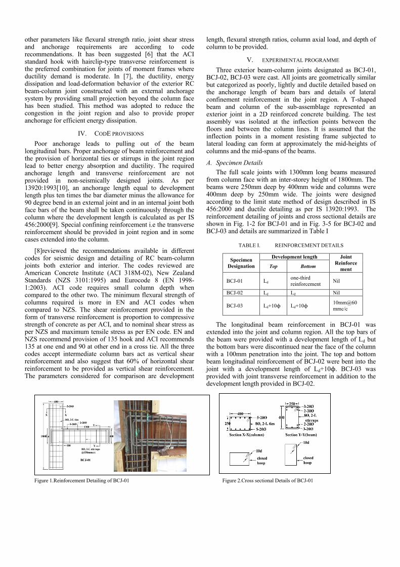
The full scale joints with 1300mm long beams measured from column face with an inter-storey height of 1800mm. The beams were 250mm deep by 400mm wide and columns were 400mm deep by 250mm wide. The joints were designed according to the limit state method of design described in IS 456:2000 and ductile detailing as per IS 13920:1993. The reinforcement detailing of joints and cross sectional details are shown in Fig. 1-2 for BCJ-01 and in Fig. 3-5 for BCJ-02 and BCJ-03 and details are summarized in Table I
TABLE I. REINFORCEMENT DETAILS
The longitudinal beam reinforcement in BCJ-01 was extended into the joint and column region. All the top bars of the beam were provided with a development length of Ld but the bottom bars were discontinued near the face of the column with a 100mm penetration into the joint. The top and bottom beam longitudinal reinforcement of BCJ-02 were bent into the joint with a development length of Ld+10ϕ. BCJ-03 was provided with joint transverse reinforcement in addition to the development length provided in BCJ-02.
Figure 1.Reinforcement Detailing of BCJ-01 Figure 2.Cross sectional Details of BCJ-01
Specimen
Designation
Development length Joint
Reinforce
ment Top Bottom
BCJ-01 Ld one-third
reinforcement Nil
BCJ-02 Ld Ld Nil
BCJ-03 Ld+10ϕ Ld+10ϕ 10mm@60
mmc/c

Figure 3. Reinforcement Detailing of BCJ-02
Figure 5. Cross sectional details of BCJ-02 and BCJ-03
Figure 4. Reinforcement Detailing of BCJ-03
This was done to study the effect of joint transverse reinforcement on the joint behavior. Joint transverse reinforcement was calculated as per [10].
B. Casting
The joints were cast in vertical position in a wooden mould.The formwork for casting of joints was prepared using 12mm waterproof plywood sheets. Each panel of the formwork had wooden stiffeners to provide transverse strength and avoid bulging. The formwork was assembled by joining all the panels with nuts and bolt system.The mould was made in such a way that all the panels can be detached after 24hours of casting for surface curing of joints. The bottom support of beam and column were kept in place, to avoid excessive deflection, until it gains required strength. All the possible leakage paths of the formwork were sealed to avoid any leakage of cement slurry. Before casting of specimen the inner surface of the formwork was applied with a layer of oil for its easy removal.
The concrete mix proportions used for casting the joints were based on IS 10262:2008. The concrete mix proportions were 1:0.5:1.42:3.1(Cement:Water:FineAggregate:Coarse Aggregate). Along with each test joint, 150mm standard cubes were cast. The specimens were water cured for 28days. The compressive strength of the concrete achieved at the age of 28 days is 45N/mm2. The yield strength of longitudinal steel bars and stirrups is 415N/mm2 and 415N/mm2 respectively. The cover to the longitudinal bars was maintained at 25mm for all the units.
C. Test set-up
The joints were subjected to quasi-static push-pull and a constant axial compression. The test set-up is shown in Fig. 6 and schematic diagram in Fig. 7. The axial force was uniformly distributed to the column cross-section with the help of two capping boxes at top and bottom of the column ends. The internal dimensions of the capping box are 250mm x 400mm x 150mm and fabricated with 25mm thick MS plates.
Figure 6. Test set-up arrangement for joints
The rotation of the column was allowed but lateral displacement of the column was arrested by hinge arrangement attached to capping box. The axial load was

applied through a hydraulic jack connected at the bottom part of the set up. The bottom assembly for the hydraulic jack and hinge support for the bottom end of the column, which was connected to the strong floor. Reversed cyclic loading was applied at the tip of the beam with actuator. The end of the beam was also pinned to allow free rotation and to translate horizontal but not vertically. The actuator and the top plate with hinge were connected to 200ton reaction frame.
Figure 7. Schematic diagram for test set-up arrangement
D. Loading
Cyclic load on the beam end was applied through a hydraulic actuator of capacity 500kN. The actuator has a closed loop servo control system. A load controlled hydraulic jack of capacity 750kN was used to apply a constant axial load of 10% of column capacity. The value of axial load was calculated based on a normalized average axial stress of 0.1fckAg in the column, which was normalized as a function of concrete compressive strength. Ag is the cross sectional area of the column. The application of displacement amplitudes has been followed as per FEMA 461 guidelines. The loading history is shown in Fig. 8.Each displacement value was applied for two cycles. Each reversed cycle of loading consisted of push and pull. Push is “negative” and is downwards and pull is “positive” and is upwards. The specimen experienced same peak displacement value in both push and pull directions.
Figure 8. Cyclic Displacement History
E. Instrumentation
Electrical resistant strain gauges mounted on different reinforcement bars measured strains in the steel. Strain gauge arrangement is shown in Figs. 9-11 in BCJ-01, BCJ-02 and BCJ-03. The displacements in concrete during testing was monitored by linear variable differential transducers (LVDT) placed at different locations. LVDTs and strain gauges were connected to a data acquisition system.
Figure 9. Strain gauge location for BCJ-01
Figure 10. Strain gauge location for BCJ-02
Figure 11. Strain gauge location for BCJ-03
Eleven LVDTs were mounted to measure the diagonal deformations on both faces of the joint, top and bottom displacements of column, total joint rotation, and deflection at the beam tip under loading as shown in Fig. 12.
-2.5
-2 -1.5
-1 -0.5
0 0.5
1 1.5
2 2.5
Δi/Δ
u
cycles
Loading History
cyclic_loading
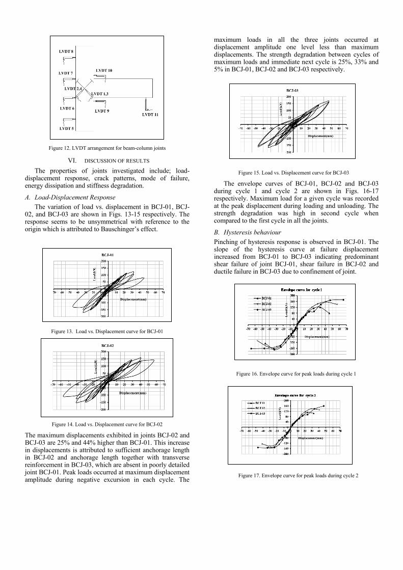
Figure 12. LVDT arrangement for beam-column joints
VI. DISCUSSION OF RESULTS
The properties of joints investigated include; load-displacement response, crack patterns, mode of failure, energy dissipation and stiffness degradation.
A. Load-Displacement Response
The variation of load vs. displacement in BCJ-01, BCJ-02, and BCJ-03 are shown in Figs. 13-15 respectively. The response seems to be unsymmetrical with reference to the origin which is attributed to Bauschinger’s effect.
Figure 13. Load vs. Displacement curve for BCJ-01
Figure 14. Load vs. Displacement curve for BCJ-02
The maximum displacements exhibited in joints BCJ-02 and BCJ-03 are 25% and 44% higher than BCJ-01. This increase in displacements is attributed to sufficient anchorage length in BCJ-02 and anchorage length together with transverse reinforcement in BCJ-03, which are absent in poorly detailed joint BCJ-01. Peak loads occurred at maximum displacement amplitude during negative excursion in each cycle. The
maximum loads in all the three joints occurred at displacement amplitude one level less than maximum displacements. The strength degradation between cycles of maximum loads and immediate next cycle is 25%, 33% and 5% in BCJ-01, BCJ-02 and BCJ-03 respectively.
Figure 15. Load vs. Displacement curve for BCJ-03
The envelope curves of BCJ-01, BCJ-02 and BCJ-03 during cycle 1 and cycle 2 are shown in Figs. 16-17 respectively. Maximum load for a given cycle was recorded at the peak displacement during loading and unloading. The strength degradation was high in second cycle when compared to the first cycle in all the joints.
B. Hysteresis behaviour
Pinching of hysteresis response is observed in BCJ-01. The slope of the hysteresis curve at failure displacement increased from BCJ-01 to BCJ-03 indicating predominant shear failure of joint BCJ-01, shear failure in BCJ-02 and ductile failure in BCJ-03 due to confinement of joint.
Figure 16. Envelope curve for peak loads during cycle 1
Figure 17. Envelope curve for peak loads during cycle 2
C. Crack pattern
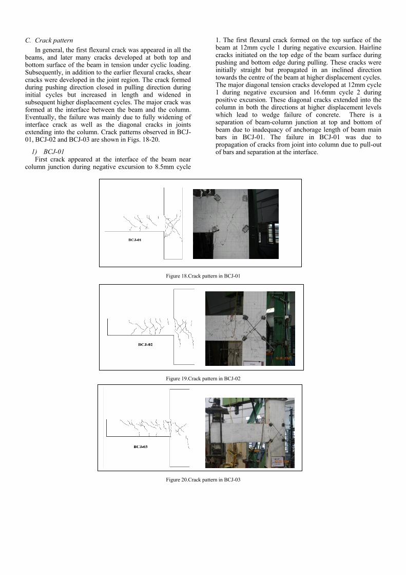
In general, the first flexural crack was appeared in all the beams, and later many cracks developed at both top and bottom surface of the beam in tension under cyclic loading. Subsequently, in addition to the earlier flexural cracks, shear cracks were developed in the joint region. The crack formed during pushing direction closed in pulling direction during initial cycles but increased in length and widened in subsequent higher displacement cycles. The major crack was formed at the interface between the beam and the column. Eventually, the failure was mainly due to fully widening of interface crack as well as the diagonal cracks in joints extending into the column. Crack patterns observed in BCJ-01, BCJ-02 and BCJ-03 are shown in Figs. 18-20.
1) BCJ-01 First crack appeared at the interface of the beam near
column junction during negative excursion to 8.5mm cycle
1. The first flexural crack formed on the top surface of the beam at 12mm cycle 1 during negative excursion. Hairline cracks initiated on the top edge of the beam surface during pushing and bottom edge during pulling. These cracks were initially straight but propagated in an inclined direction towards the centre of the beam at higher displacement cycles. The major diagonal tension cracks developed at 12mm cycle 1 during negative excursion and 16.6mm cycle 2 during positive excursion. These diagonal cracks extended into the column in both the directions at higher displacement levels which lead to wedge failure of concrete. There is a separation of beam-column junction at top and bottom of beam due to inadequacy of anchorage length of beam main bars in BCJ-01. The failure in BCJ-01 was due to propagation of cracks from joint into column due to pull-out of bars and separation at the interface.
Figure 18.Crack pattern in BCJ-01
Figure 19.Crack pattern in BCJ-02
Figure 20.Crack pattern in BCJ-03
1) BCJ-02 The first crack formed on the top surface of the beam at
12mm cycle 1 during negative excursion. Hairline cracks initiated on the top edge of the beam surface during pushing and bottom edge during pulling. These cracks were initially straight but propagated in an inclined direction towards the centre of the beam at higher displacement cycles but with less inclination than those of BCJ-01. The major diagonal tension cracks developed at 14.9mm cycle 1 during negative excursion and 20.8mm cycle 2 during positive excursion. These diagonal cracks extended to the lower portion of the column especially during positive excursion. In BCJ-02, due to adequate anchorage length of beam bars, separation of beam-column junction at top and bottom was not severe. However, the failure in BCJ-02 was due to interface separation.
2) BCJ-03 First crack appeared at the top surface of the beam
towards the column face during negative excursion to 8.7mm cycle 2. Hairline cracks initiated on the top edge of the beam surface during pushing and bottom edge during pulling. These cracks were initially straight but propagated in an inclined direction towards the centre of the beam at higher displacement cycles. The provision of joint reinforcement and adequate anchorage length of beam bars in joints BCJ-03, exhibited less cracking in the joint region and no propagation of cracks from core to the column region. More distributed cracking was observed in the beam region. Final failure in BCJ-03 is due to interface crack. The shear strength of joint was significantly high due to use of joint reinforcement.
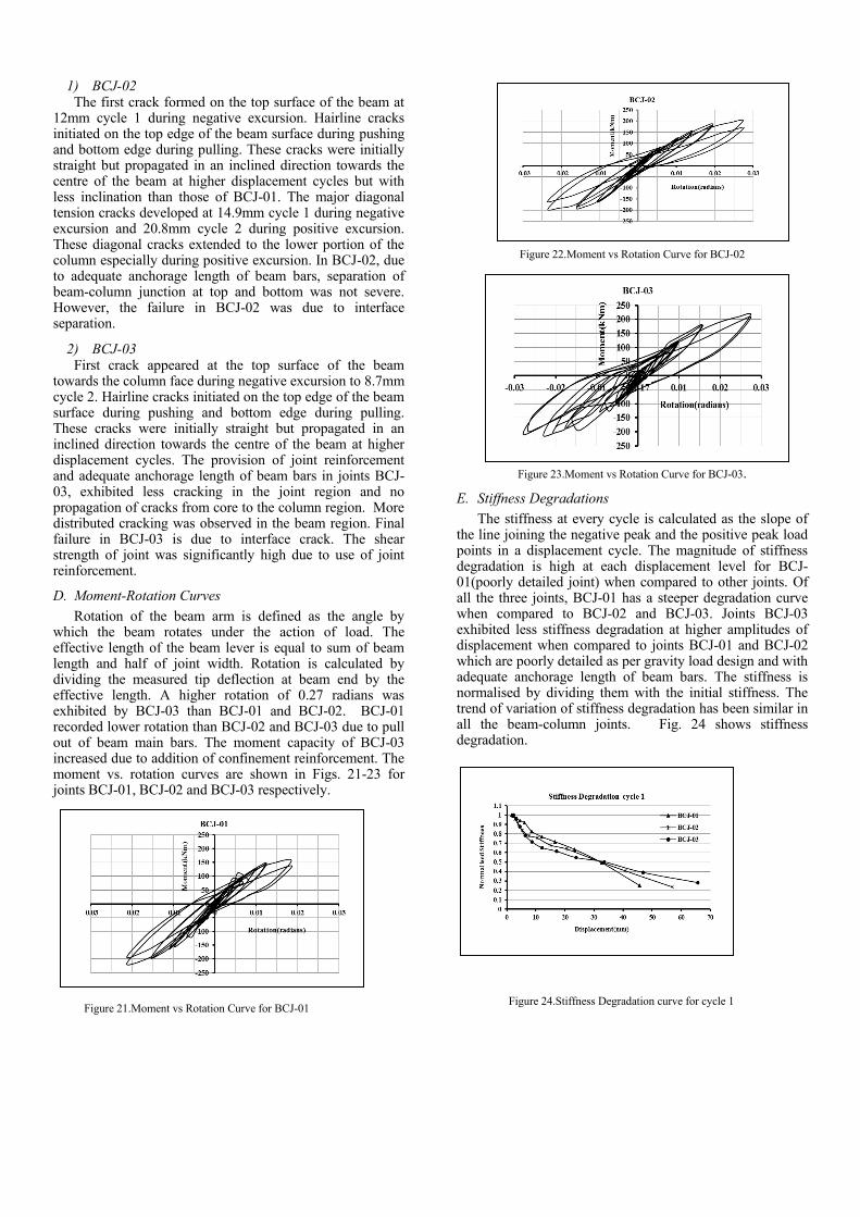
D. Moment-Rotation Curves
Rotation of the beam arm is defined as the angle by which the beam rotates under the action of load. The effective length of the beam lever is equal to sum of beam length and half of joint width. Rotation is calculated by dividing the measured tip deflection at beam end by the effective length. A higher rotation of 0.27 radians was exhibited by BCJ-03 than BCJ-01 and BCJ-02. BCJ-01 recorded lower rotation than BCJ-02 and BCJ-03 due to pull out of beam main bars. The moment capacity of BCJ-03 increased due to addition of confinement reinforcement. The moment vs. rotation curves are shown in Figs. 21-23 for joints BCJ-01, BCJ-02 and BCJ-03 respectively.
Figure 21.Moment vs Rotation Curve for BCJ-01
Figure 22.Moment vs Rotation Curve for BCJ-02
Figure 23.Moment vs Rotation Curve for BCJ-03.
E. Stiffness Degradations
The stiffness at every cycle is calculated as the slope of the line joining the negative peak and the positive peak load points in a displacement cycle. The magnitude of stiffness degradation is high at each displacement level for BCJ-01(poorly detailed joint) when compared to other joints. Of all the three joints, BCJ-01 has a steeper degradation curve when compared to BCJ-02 and BCJ-03. Joints BCJ-03 exhibited less stiffness degradation at higher amplitudes of displacement when compared to joints BCJ-01 and BCJ-02 which are poorly detailed as per gravity load design and with adequate anchorage length of beam bars. The stiffness is normalised by dividing them with the initial stiffness. The trend of variation of stiffness degradation has been similar in all the beam-column joints. Fig. 24 shows stiffness degradation.
Figure 24.Stiffness Degradation curve for cycle 1

F. Energy Dissipation
Energy dissipated in the joint can be calculated as the area under the load vs. displacement curve. The area for each cycle is calculated and then summed up for the cumulative energy dissipation for the entire load and unload cycles.For comparison, the cumulative energy dissipation is normalised by dividing it by the volume of the joint and the strength of concrete. The larger hysteresis loop gives way to greater energy dissipation and this is evident in BCJ-03 due to the presence of joint reinforcement and adequate anchorage length of beam bars. Cumulative energy dissipation is compared in Fig. 25.
Figure 25.Energy Dissipation Curve
VII. CONCLUSIONS
The pull-out of the beam longitudinal bars in BCJ-01 occurred due to insufficient anchorage length which caused severe cracking in the joint region, loss of stiffness and reduction of energy dissipation capacity. Wedge failure of concrete was observed due to inability of concrete to resist the bond forces developed by beam bars and slippage of column bars due to lack of confinement. The beam bar pull out was delayed in BCJ-02 due to an anchorage length of (Ld+10ϕ)for both top and bottom beam longitudinal bars. The addition of closely spaced stirrups in the joint region as transverse reinforcement and providing adequate anchorage length of beam bars in BCJ-03 reduced the cracking of joint regionand improving the ductility, and thereby exhibiting better energy dissipation and less stiffness degradation.
REFERENCES
[1] Thomas Paulay, “Equilibrium criteria for reinforced concrete beam-column joints,” ACI Strucural Journal, vol. 86, pp. 635-643, 1989.
[2] S.J.Hwang and H.J.Lee, “Analytical model for predicting shear strengths of exterior reinforced concrete beam-column joints for seismic resistance,” ACI Strucural Journal, vol. 96, pp. 846-855, 1999.
[3] S.J.Hwang, H.J.Lee, T.F.Liao, K.C.Wang and H.H.Tsai, “Role of hoops on shear strength of reinforced concrete beam-column joints,” ACI Strucural Journal, vol. 102, pp. 445-453, 2005.
[4] J.Hegger, A.Sheriff and W.Roeser, “Nonseismic design of beam-column joints,” ACI Strucural Journal, vol. 100, pp. 654-664, 2003.
[5] M.R.Ehsani and J.K.Wight, “Exterior reinforced concrete beam-to-column connections subjected to earthquake-type loading,” ACI Structural Journal, vol. 82, pp.492-499, 1985.
[6] C.V.R.Murty, D.C.Rai, K.K. Bajpai and S.K.Jain, “Effectiveness of reinforcement details in exterior reinforced concrete beam-column joints for earthquake resistance,” ACI Strucural Journal, vol. 100, pp. 149-155, 2003.
[7] K.R.C.Siva and G.S.Thirugnanam, “Comparative study on behaviour of beam-column joints with reference to anchorage detailing,” Journal of Civil Engineering Research, vol. 2, pp. 12-17, 2012.
[8] S.R.Uma and S.K.Jain,“Seiamic design of beam-column joints in rc-moment resisting frames-review of codes,” Structural Engineering and Mechanics, vol.23,579-597, 2006.
[9] IS 456:2000, “Plain and reinforced concrete,” Code of Practice, Bureau of Indian Standards, New Delhi.
[10] IS 13920:1993, “Ductile detailing of reinforced concrete structures subjected to seismic forces,” Code of Practice, Bureau of Indian Standards, New Delhi.
[11] IS 10262:2008, “Recommended guidelines for concrete mix design,” Bureau of Indian Standards, New Delhi.


