PERFORMANCE EVALUATION OF VARIOUS CORROSION … No. CDOT-DTD-R-2004-1 . Final Report . PERFORMANCE...
141
Report No. CDOT-DTD-R-2004-1 Final Report PERFORMANCE EVALUATION OF VARIOUS CORROSION PROTECTION SYSTEMS OF BRIDGES IN COLORADO Yunping Xi Naser Abu-Hejleh Andi Asiz A. Suwito January 2004 COLORADO DEPARTMENT OF TRANSPORTATION RESEARCH BRANCH
Transcript of PERFORMANCE EVALUATION OF VARIOUS CORROSION … No. CDOT-DTD-R-2004-1 . Final Report . PERFORMANCE...
Report No. CDOT-DTD-R-2004-1 Final Report PERFORMANCE EVALUATION OF VARIOUS CORROSION PROTECTION SYSTEMS OF BRIDGES IN COLORADO Yunping Xi Naser Abu-Hejleh Andi Asiz A. Suwito
January 2004 COLORADO DEPARTMENT OF TRANSPORTATION RESEARCH BRANCH
The contents of this report reflect the views of the
author(s), who is(are) responsible for the facts and
accuracy of the data presented herein. The contents do
not necessarily reflect the official views of the Colorado
Department of Transportation or the Federal Highway
Administration. This report does not constitute a
standard, specification, or regulation.
i
ii
Technical Report Documentation Page 1. Report No. CDOT-DTD-R-2004-1
2. Government Accession No.
3. Recipient's Catalog No. 5. Report Date January 2004
4. Title and Subtitle PERFORMANCE EVALUATION OF VARIOUS CORROSION PROTECTION SYSTEMS OF BRIDGES IN COLORADO 6. Performing Organization Code
7. Author(s) Yunping Xi, Naser Abu-Hejleh, Andi Asiz, A. Suwito
8. Performing Organization Report No. CDOT-DTD-R-2004-1
10. Work Unit No. (TRAIS)
9. Performing Organization Name and Address Colorado Department of Transportation 4201 E. Arkansas Ave Denver, Colorado 80222
11. Contract or Grant No. Performed internally by CDOT-Research Office
13. Type of Report and Period Covered
12. Sponsoring Agency Name and Address Colorado Department of Transportation - Research 4201 E. Arkansas Ave. Denver, CO 80222 14. Sponsoring Agency Code
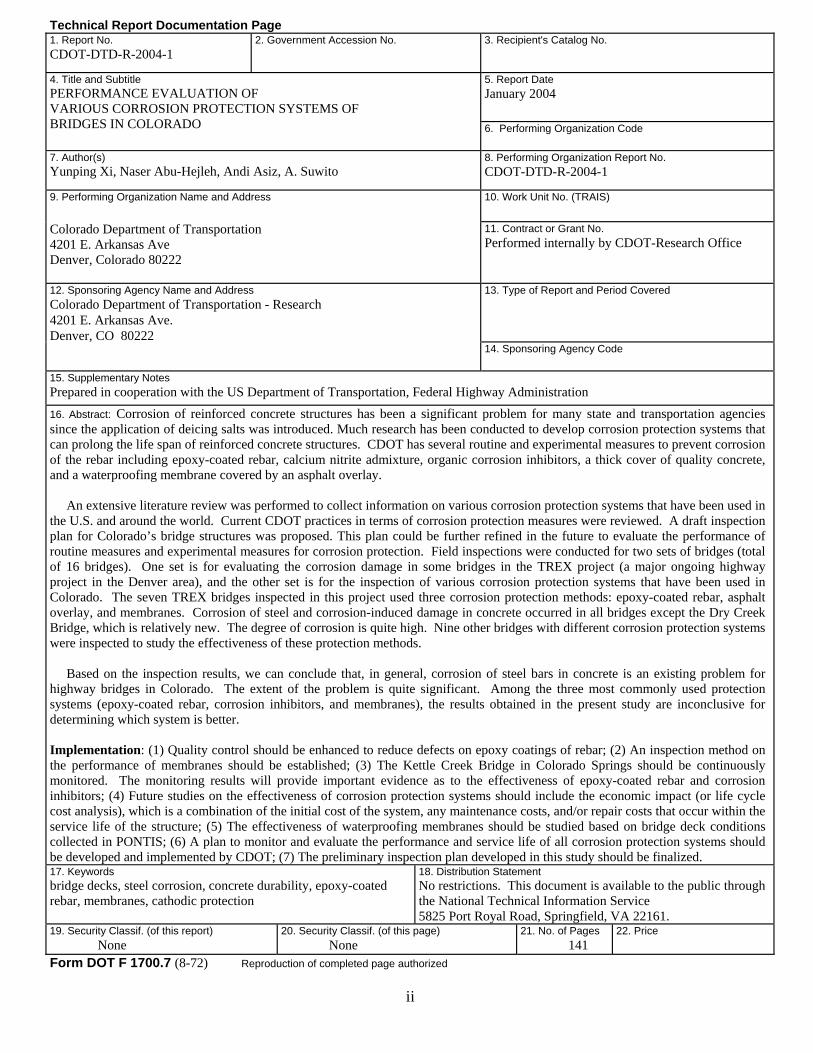
15. Supplementary Notes Prepared in cooperation with the US Department of Transportation, Federal Highway Administration 16. Abstract: Corrosion of reinforced concrete structures has been a significant problem for many state and transportation agencies since the application of deicing salts was introduced. Much research has been conducted to develop corrosion protection systems that can prolong the life span of reinforced concrete structures. CDOT has several routine and experimental measures to prevent corrosion of the rebar including epoxy-coated rebar, calcium nitrite admixture, organic corrosion inhibitors, a thick cover of quality concrete, and a waterproofing membrane covered by an asphalt overlay. An extensive literature review was performed to collect information on various corrosion protection systems that have been used in the U.S. and around the world. Current CDOT practices in terms of corrosion protection measures were reviewed. A draft inspection plan for Colorado’s bridge structures was proposed. This plan could be further refined in the future to evaluate the performance of routine measures and experimental measures for corrosion protection. Field inspections were conducted for two sets of bridges (total of 16 bridges). One set is for evaluating the corrosion damage in some bridges in the TREX project (a major ongoing highway project in the Denver area), and the other set is for the inspection of various corrosion protection systems that have been used in Colorado. The seven TREX bridges inspected in this project used three corrosion protection methods: epoxy-coated rebar, asphalt overlay, and membranes. Corrosion of steel and corrosion-induced damage in concrete occurred in all bridges except the Dry Creek Bridge, which is relatively new. The degree of corrosion is quite high. Nine other bridges with different corrosion protection systems were inspected to study the effectiveness of these protection methods.
Based on the inspection results, we can conclude that, in general, corrosion of steel bars in concrete is an existing problem for highway bridges in Colorado. The extent of the problem is quite significant. Among the three most commonly used protection systems (epoxy-coated rebar, corrosion inhibitors, and membranes), the results obtained in the present study are inconclusive for determining which system is better.
Implementation: (1) Quality control should be enhanced to reduce defects on epoxy coatings of rebar; (2) An inspection method on the performance of membranes should be established; (3) The Kettle Creek Bridge in Colorado Springs should be continuously monitored. The monitoring results will provide important evidence as to the effectiveness of epoxy-coated rebar and corrosion inhibitors; (4) Future studies on the effectiveness of corrosion protection systems should include the economic impact (or life cycle cost analysis), which is a combination of the initial cost of the system, any maintenance costs, and/or repair costs that occur within the service life of the structure; (5) The effectiveness of waterproofing membranes should be studied based on bridge deck conditions collected in PONTIS; (6) A plan to monitor and evaluate the performance and service life of all corrosion protection systems should be developed and implemented by CDOT; (7) The preliminary inspection plan developed in this study should be finalized. 17. Keywords bridge decks, steel corrosion, concrete durability, epoxy-coated rebar, membranes, cathodic protection
18. Distribution Statement No restrictions. This document is available to the public through the National Technical Information Service 5825 Port Royal Road, Springfield, VA 22161.
19. Security Classif. (of this report) None
20. Security Classif. (of this page) None
21. No. of Pages 141
22. Price
Form DOT F 1700.7 (8-72) Reproduction of completed page authorized
iii
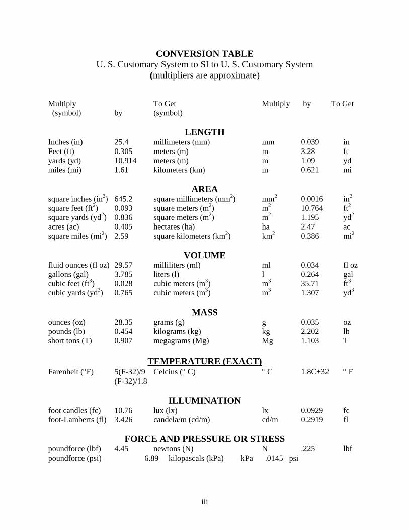
CONVERSION TABLE U. S. Customary System to SI to U. S. Customary System
(multipliers are approximate)
Multiply To Get Multiply by To Get (symbol) by (symbol)
LENGTH Inches (in) 25.4 millimeters (mm) mm 0.039 in Feet (ft) 0.305 meters (m) m 3.28 ft yards (yd) 10.914 meters (m) m 1.09 yd miles (mi) 1.61 kilometers (km) m 0.621 mi
AREA square inches (in2) 645.2 square millimeters (mm2) mm2 0.0016 in2
square feet (ft2) 0.093 square meters (m2) m2 10.764 ft2
square yards (yd2) 0.836 square meters (m2) m2 1.195 yd2
acres (ac) 0.405 hectares (ha) ha 2.47 ac square miles (mi2) 2.59 square kilometers (km2) km2 0.386 mi2
VOLUME
fluid ounces (fl oz) 29.57 milliliters (ml) ml 0.034 fl oz gallons (gal) 3.785 liters (l) l 0.264 gal cubic feet (ft3) 0.028 cubic meters (m3) m3 35.71 ft3
cubic yards (yd3) 0.765 cubic meters (m3) m3 1.307 yd3
MASS
ounces (oz) 28.35 grams (g) g 0.035 oz pounds (lb) 0.454 kilograms (kg) kg 2.202 lb short tons (T) 0.907 megagrams (Mg) Mg 1.103 T
TEMPERATURE (EXACT) Farenheit (°F) 5(F-32)/9 Celcius (° C) ° C 1.8C+32 ° F (F-32)/1.8
ILLUMINATION foot candles (fc) 10.76 lux (lx) lx 0.0929 fc foot-Lamberts (fl) 3.426 candela/m (cd/m) cd/m 0.2919 fl
FORCE AND PRESSURE OR STRESS poundforce (lbf) 4.45 newtons (N) N .225 lbf poundforce (psi) 6.89 kilopascals (kPa) kPa .0145 psi

Performance Evaluation of Various Corrosion Protection Systems of Bridges in Colorado
by
Yunping Xi, University of Colorado at Boulder Naser Abu-Hejleh, Colorado DOT (Research Branch)
Andi Asiz, University of Colorado at Boulder A. Suwito, University of Colorado at Boulder
Report No. CDOT-DTD-R-2004-1
Sponsored by the Colorado Department of Transportation
January 2004
Colorado Department of Transportation Research Branch
4201 E. Arkansas Ave. Denver, CO 80222
(303) 757-9506
iv

Acknowledgements The financial support provided by the Colorado Department of Transportation for this study under PG HAA 01HQ0000286 00HAA00069 (Task Order #7) is gratefully acknowledged. Partial financial support under NSF grant CMS-9872379 to the University of Colorado at Boulder is greatly acknowledged. Partial financial support under NSF grant ACI-0112930 to the University of Colorado at Boulder is gratefully acknowledged. Partial financial support provided by the FHWA and Colorado Department of Transportation under FCU-CX 083-1(049) 00HAA00069 (Task Order #2) is gratefully acknowledged. The writers would like to express their thanks to the Colorado DOT for continuous support and encouragement throughout this study, and specifically to Skip Outcalt, Ahmad Ardani and Richard Griffin of the CDOT Research Branch; Michael McMullen Trever Wang, and Ali Haraj of the CDOT Staff Bridge; Greg Lowery of CDOT Staff Materials; and Matt Greer of FHWA for their valuable suggestions and input. The writers would also like to express their thanks to Ms. Lindsay Marshall for careful editing of the report.
v

Executive Summary
The corrosion of reinforcement in concrete is a very important, long-term durability problem for concrete bridge decks. The rust formation from corroding steel results in bond deterioration between the steel and concrete and in the acceleration of cracking and spalling of the concrete. In turn, the damaged concrete with a high permeability leads to a rapid penetration of aggressive chemicals into the concrete. Much research has been conducted to develop corrosion protection systems that can prolong the life span of reinforced concrete structures. CDOT uses several routine and experimental measures to prevent corrosion of the rebar including epoxy-coated rebar, calcium nitrite admixture, organic corrosion inhibitors, a thick cover of quality concrete, and a waterproofing membrane covered by an asphalt overlay. Where a bare concrete deck is desired, Region 6 has been topping the deck with two inches of silica fume concrete. Silica fume concrete has very low permeability, which slows the penetration of chloride to the rebar.
CDOT does not have sufficient information about the effectiveness of the protective systems used in the bridge structures. CDOT has limited data on the influential parameters for steel corrosion, especially chloride penetration in bridge decks. This information is needed to optimize CDOT’s strategies against the corrosion problem in bridge structures. The present study is the first attempt in Colorado to address some of the important issues related to corrosion protection systems used for highway bridges. The study has the following objectives:
• To determine the extent of the steel corrosion problem in Colorado’s existing reinforced concrete structures (i.e., bridge deck, pier caps, abutment seats, and locations around the joints) and how critical the problem is.
• Provide recommendations to enhance CDOT’s current guidelines for corrosion projection of reinforcing steel in Colorado bridge structures.
An extensive literature review was performed to collect information on various corrosion
protection systems that have been used in the U.S. and around the world, including thickness and quality of concrete cover; membranes and sealers; alternative reinforcements such as epoxy-coated rebar; steel bars with metallic coating and cladding (galvanized rebars, stainless steel, copper-clad); alternative solid bars (CFRP, GFRP, etc); electrochemical methods (cathodic protection, electrochemical realkalization, electrochemical chloride extraction); and corrosion inhibiting admixtures. Basic principles such as the strengths and weaknesses of the corrosion protection methods are reviewed.
Current CDOT practices in terms of corrosion protection measures were reviewed. The
application of some of the systems in Colorado are discussed and summarized. The CDOT and FHWA specifications and technical documentations related to corrosion protection are reviewed.
A draft inspection plan for Colorado’s bridge structures was proposed that could be
further refined in the future to evaluate the performance of routine measures and experimental measures for corrosion protection.
vi

Field inspections were conducted for two sets of bridges (total of 16 bridges). One set was for evaluating the corrosion damage in some bridges in the TREX project (a major ongoing highway project in the Denver area), and the other set was for the inspection of various corrosion protection systems that have been used in Colorado. The seven TREX bridges inspected in this project used three corrosion protection methods: epoxy-coated rebar, asphalt overlay, and membranes. Corrosion of steel and corrosion-induced damage in concrete occurred in all bridges except the Dry Creek Bridge, which is relatively new. The degree of corrosion is quite high. Nine other bridges with different corrosion protection systems were inspected to study the effectiveness of these protection methods which include:
• Asphalt overlay with membrane (I-70 over Moss St and Yosemite over I-25). • Epoxy-coated rebar and corrosion inhibitor (Kettle Creek Bridge and Wolfensburger
Bridges in Colorado Springs). • Impressed-current cathodic protection method (two bridges on I-70 EB at mileposts 293
and 294). • Sacrificial anode cathodic protection method (i.e., Galvashield) with asphalt overlays
(two bridges on SH 85 and SH 34 in Greeley).
The inspection covered fieldwork such as visual inspection for corrosion induced damages, crack mapping, chain dragging, taking photos for efflorescence and spalling, and laboratory work to determine chloride profiling (chloride ion concentration as a function of concrete depth). The inspected structural components included top deck and bottom deck, pier caps, piers, and girder systems.
Based on the inspection results, we can conclude in general that the corrosion of steel
bars in concrete is an existing problem for highway bridges in Colorado. The extent of the problem is quite significant. Among the three most commonly used protection systems (epoxy-coated rebar, corrosion inhibitors, and membranes), the results obtained in the present study are inconclusive for determining which system is better. Some specific conclusions are as follows:
• Bridge geometry plays an important role in the corrosion resistance of structural components. Curved and skewed bridges can lead to the flow of deicing salt solution from decks onto other structural components such as pier caps and piers if the drainage system is not in good condition. Therefore, proper drainage should be provided so that the water can drain quickly from the deck. Seepage drains should be provided at low points to prevent water from sitting on top of the membrane.
• The application of the cathodic protection method is quite effective in prolonging the
life of the bridge decks that would otherwise need to be replaced.
• Although some references have stated the superior performance of corrosion inhibiting admixtures, the results of the inspection of Kettle Creek Bridge in Colorado Springs showed some areas of weakness which cause some concerns. The rebar protected by the
vii
concrete cover with corrosion inhibiting admixtures is more vulnerable to corrosion than that of epoxy-coated rebar when significant cracks are present in the deck.
Implementation Statement
Quality control should be enhanced to reduce defects on epoxy coatings of rebar. If it is economically viable and is needed, use epoxy coating as well as corrosion inhibitors as a double-corrosion protection measure.
The effectiveness of a membrane depends heavily on service time, traffic load, and
weather conditions. An inspection method on the performance of membranes should be established.
The Kettle Creek Bridge in Colorado Springs should be continuously monitored. The
monitoring results will provide important evidence as to the effectiveness of epoxy-coated rebar and corrosion inhibitors.
It is recommended that future studies on the effectiveness of corrosion protection systems
include economic impact (or life cycle cost analysis), which is a combination of the initial cost of the system, any maintenance costs, and/or repair costs that occur within the service life of the structure.
It is recommended that the effectiveness of waterproofing membranes be studied based on bridge deck conditions collected in PONTIS in a future research study.
A follow-up study is very important and necessary. The follow-up study should develop
a plan to monitor and evaluate the performance and service life of all corrosion protection systems employed by CDOT. More information affecting the performance of the corrosion protection systems should be collected. Coring and the half-cell potential measurements should be considered as new inspection methods for the extent of corrosion in bridge decks. The study should finalize the preliminary inspection plan developed in this study, and develop a revision to Section 202 of CDOT Standard Specifications to allow testing of all demolished, repaired, and widened bridge decks.
viii

TABLE OF CONTENTS
1. Introduction................................................................................................................................. 1
1.1. Background.......................................................................................................................... 1 1.2. Scope and Objective of the Study........................................................................................ 3
2. Literature Review Relevant to CDOT Practice .......................................................................... 4
2.1 Steel Corrosion in Reinforced Concrete ............................................................................... 4 2.1.1 Steel Corrosion in Concrete ......................................................................................... 4 2.1.2 Critical Chloride Concentration ................................................................................... 5
2.2 Corrosion Control in New Concrete Bridges........................................................................ 6 2.2.1 Concrete Cover............................................................................................................. 6 2.2.2 Alternative Reinforcements.......................................................................................... 7 2.2.3 Corrosion Inhibiting Admixtures ............................................................................... 12
2.3 Corrosion Control for Existing Concrete Bridges .............................................................. 14 2.3.1 Conventional Rehabilitation Methods........................................................................ 14 2.3.2 Unconventional Rehabilitation Methods.................................................................... 17
3. Current CDOT Practice Regarding Corrosion Protection ........................................................ 20
3.1 Quality and Durable Concrete ............................................................................................ 20 3.2 Concrete Cover over Reinforcing Steel .............................................................................. 21 3.3 Waterproofing Membrane with Asphalt Overlays.............................................................. 21 3.4 Epoxy-Coated Rebar (ECR) ............................................................................................... 22 3.5 Corrosion Inhibitors............................................................................................................ 23 3.6 Cathodic Protection Systems .............................................................................................. 23 3.7 Use of FRP to Replace Steel Bars ...................................................................................... 24 3.8 100% FRP Decks ................................................................................................................ 25 3.9 Use of Sealers ..................................................................................................................... 26 3.10 Repair of Bridge Decks..................................................................................................... 26
4. Inspection Plan for Evaluating the Performance of Various Corrosion Protection Systems.... 28
5. Results of Field Inspections ...................................................................................................... 31
5.1 List of Bridges for Inspection ............................................................................................. 31 5.2 Inspection Results of T-REX Bridges ................................................................................ 33
5.2.1 I-25 over Arapahoe (based on an interview with TREX personnel).......................... 34 5.2.2 I-25 over Orchard (north bound) ................................................................................ 34 5.2.3 I-25 over Dry Creek – South Bound .......................................................................... 34 5.2.4 I-25 over Belleview – North Bound........................................................................... 35 5.2.5 Hampden over I-25..................................................................................................... 35 5.2.6 Emerson over I-25...................................................................................................... 35 5.2.7 I-25 over University Boulevard.................................................................................. 36
5.3 Inspection Results of Bridges with Various Corrosion Protection Systems....................... 36 5.3.1 The Bridge on SH 85 in Greeley................................................................................ 36 5.3.2 The Bridge on SH34-Business Route in Greeley....................................................... 38 5.3.3 Wolfensburger Rd. WB over I-25 .............................................................................. 39
ix

5.3.4 Wolfensburger Rd. WB over Plum Creek.................................................................. 40 5.3.5 Kettle Creek Bridge on SH 83 – Colorado Springs ................................................... 41 5.3.6 Bridge on I-70EB on MP 293.6 ................................................................................. 47 5.3.7 Bridge on I-70 on MP 294.7....................................................................................... 49 5.3.8 I-70 EB over Moss St ................................................................................................. 50 5.3.9 Yosemite over I-25..................................................................................................... 52
6. Conclusions and Recommendations ........................................................................................ 53
6.1 Literature Review ............................................................................................................... 53 6.2 Inspection Results of TREX Bridges.................................................................................. 53 6.3 Inspection Results on Various Corrosion Protection Systems............................................ 53 6.4 Conclusion Remarks .......................................................................................................... 55
7. References................................................................................................................................ 57
Appendix A - SmartFlag 359 - Soffit of Concrete Decks and Slabs Appendix B1 - TREX Bridges - Inspection Results Appendix B2 - TREX Bridges - Chloride Concentration Profiles Appendix C - Inspection Results (photos and crack mapping) Appendix D - Chloride Profiles of the Inspected Bridges
x
LIST OF FIGURES Fig. 1.1 Corroded steel bars on one of the bridges in I-70.............................................................. 1 Fig. 1.2 Corrosion damage on pier caps ......................................................................................... 1 Fig. 2.1 The appearance of epoxy-coated rebars from distance. .................................................... 8 Fig. 2.2 A close view of the epoxy-coated rebars. Surface damages can be seen. ...................... 8 Fig. 2.3 A close view of the epoxy-coated rebars. Corrosion started on the locations with
damaged coatings.................................................................................................................... 9 Fig. 2.4 A regular realkalization system ....................................................................................... 19 Fig. 3.1 Castlewood Canyon Bridge ............................................................................................. 21 Fig. 3.2 Repair corrosion damage on the arch .............................................................................. 21 Fig. 3.3 The Galvashield cathodic protection system installed in SH 85 SB in Greeley, Colorado.
............................................................................................................................................... 24Fig. 3.4 A close view of the Galvashield cathodic protection system. ......................................... 24 Fig. 3.5 I-225 & Parker Interchange project ................................................................................. 25 Fig. 3.6 Prestressing bridge decks using CFRP ............................................................................ 25 Fig. 3.7 Installation of GFRP decks in O’Fallon Park Bridge (Denver, Colorado)...................... 25 Fig. 3.8 Construction of GFRP panels (on the top surface are wires for embedded fiber optic
sensors). ................................................................................................................................ 25 Fig. 3.9 Concrete deck (with steel girder) repair details............................................................... 26 Fig. 3.10 Concrete deck (with concrete girder) repair details....................................................... 27 Fig. 5.1 The TREX project. .......................................................................................................... 31 Fig. 5.2 Configuration of corrosion measuring/monitoring probes ............................................. 42 Fig. 5.3 The locations of the embedded probes in the concrete deck ........................................... 43 Fig. 5.4 Potential map of steel reinforcement in concrete with calcium nitrite inhibitor .......... 45 Fig. 5.5 Potential map of epoxy-coated reinforcement in concrete ........................................... 46
xi

LIST OF TABLES Table 2.1 Critical chloride contents suggested in the literature..................................................... 5 Table 5.1 List of TREX bridges inspected.................................................................................... 32 Table 5.2 List of bridges inspected with various corrosion protection systems ........................... 33
xii
1. Introduction 1.1. Background
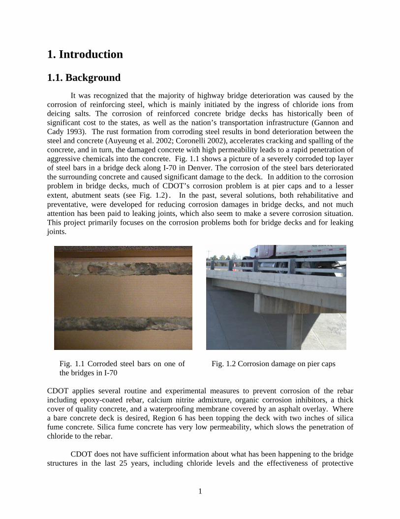
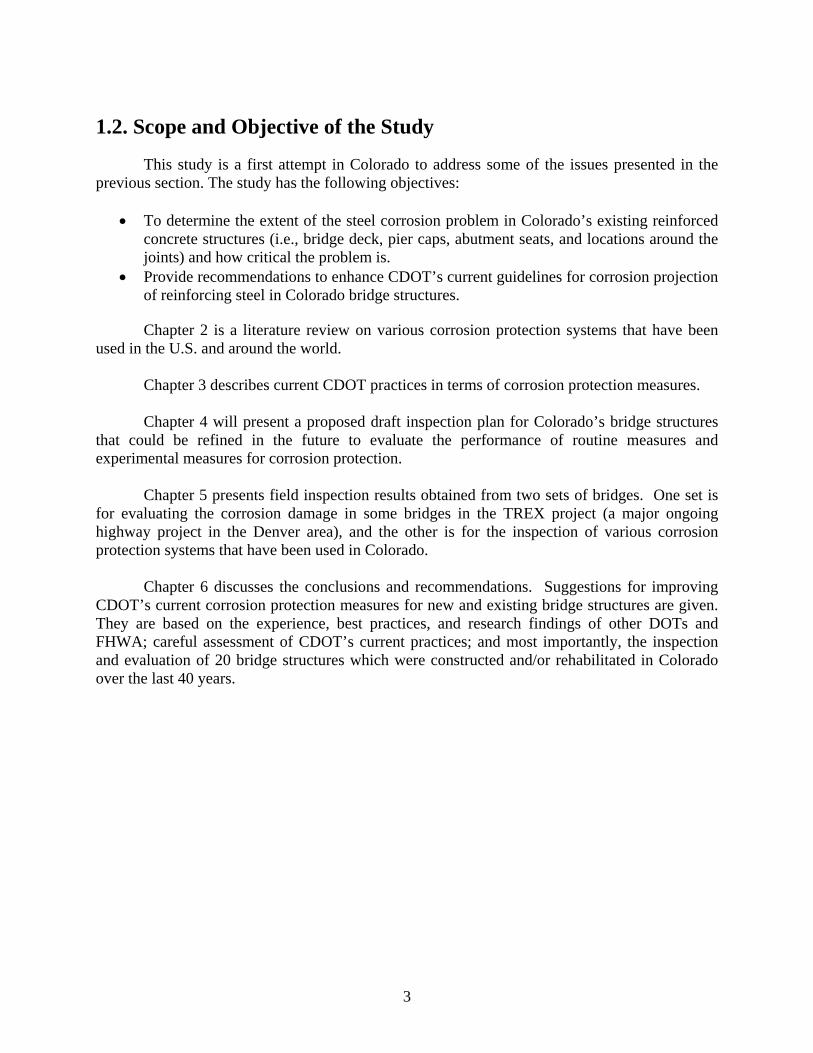
It was recognized that the majority of highway bridge deterioration was caused by the corrosion of reinforcing steel, which is mainly initiated by the ingress of chloride ions from deicing salts. The corrosion of reinforced concrete bridge decks has historically been of significant cost to the states, as well as the nation’s transportation infrastructure (Gannon and Cady 1993). The rust formation from corroding steel results in bond deterioration between the steel and concrete (Auyeung et al. 2002; Coronelli 2002), accelerates cracking and spalling of the concrete, and in turn, the damaged concrete with high permeability leads to a rapid penetration of aggressive chemicals into the concrete. Fig. 1.1 shows a picture of a severely corroded top layer of steel bars in a bridge deck along I-70 in Denver. The corrosion of the steel bars deteriorated the surrounding concrete and caused significant damage to the deck. In addition to the corrosion problem in bridge decks, much of CDOT’s corrosion problem is at pier caps and to a lesser extent, abutment seats (see Fig. 1.2). In the past, several solutions, both rehabilitative and preventative, were developed for reducing corrosion damages in bridge decks, and not much attention has been paid to leaking joints, which also seem to make a severe corrosion situation. This project primarily focuses on the corrosion problems both for bridge decks and for leaking joints.
Fig. 1.1 Corroded steel bars on one of the bridges in I-70
Fig. 1.2 Corrosion damage on pier caps
CDOT applies several routine and experimental measures to prevent corrosion of the rebar including epoxy-coated rebar, calcium nitrite admixture, organic corrosion inhibitors, a thick cover of quality concrete, and a waterproofing membrane covered by an asphalt overlay. Where a bare concrete deck is desired, Region 6 has been topping the deck with two inches of silica fume concrete. Silica fume concrete has very low permeability, which slows the penetration of chloride to the rebar.
CDOT does not have sufficient information about what has been happening to the bridge structures in the last 25 years, including chloride levels and the effectiveness of protective
1

systems used in the structures. CDOT engineers have been informed that membrane-protected structures can last at least 25 years and bare deck structures can last about 10 years. Data should be collected to determine how effectively membranes protect bridge decks and to quantify problems associated with the membranes, such as debonding and shoving of the asphalt wearing surface. Therefore, recommendations can be obtained for a policy on the use of waterproofing membranes in lieu of, or in addition to, other measures to protect bridge decks from corrosion.
There have been many approaches taken by various states to prevent and remedy the corrosion damages to concrete structures. Of particular interest are the studies of remedial measures for existing bridges, such as chloride extraction technique, sealers (e.g., silane, methyaculate), and protective systems (e.g., sprayed zinc cathodic protection) to existing bridges.
CDOT has limited data on the influential parameters for steel corrosion, especially chloride penetration in bridge decks. This information is needed to optimize CDOT’s strategies against the corrosion problem in bridge structures. To this purpose, the current CDOT database must be extended and in order to do so, further inspection information on the corrosion behavior of reinforced concrete bridge decks and joints is needed. The inspection information collected over the life of the corrosion protection system could be utilized to study the performance of these protective systems and to estimate their reaming life. There have been many approaches for prevention and remediation of corrosion-induced damage that have been taken by many states and that could be used to improve CDOT practice. Therefore, there is a pressing need to evaluate CDOT’s current corrosion protection measures, so that the methods of other DOTs which would most benefit CDOT can be applied.
This study and future similar research studies have been proposed to address many
important critical issues for CDOT: • Is CDOT’s current approach to preventing corrosion of bridge deck rebars effective? The
high cost of repairing damage caused by corroding rebar makes this question a very critical one. CDOT is one of the few states to choose protective membranes as a preventative measure. This makes it difficult for CDOT to apply the experiences of other states, because the use of an ample cover of quality concrete and epoxy-coated rebar is more common in other states.
• Is CDOT’s current approach to prevent corrosion of bridge deck rebar cost-effective? The
use of multiple protective measures may be overkill in some situations. Perhaps there may be other protective measures that would be as effective at a lower cost. However, the high cost of repair indicates a need for caution before modifying the current approach.
• CDOT has used other protective measures to prevent corrosion of rebar including a silica
fume concrete topping, calcium nitrite, and cathodic protection systems. How does the performance of these measures compare to CDOT’s standard approach?
• No precise information is available on the effectiveness of methyaculate for sealing joints
and cracks in bridge decks, and for the application of silane on new bridge decks. Is silane coating effective for old structures? How does it compare to asphalt and membrane?
2
1.2. Scope and Objective of the Study
This study is a first attempt in Colorado to address some of the issues presented in the previous section. The study has the following objectives:
• To determine the extent of the steel corrosion problem in Colorado’s existing reinforced concrete structures (i.e., bridge deck, pier caps, abutment seats, and locations around the joints) and how critical the problem is.
• Provide recommendations to enhance CDOT’s current guidelines for corrosion projection of reinforcing steel in Colorado bridge structures.
Chapter 2 is a literature review on various corrosion protection systems that have been
used in the U.S. and around the world.
Chapter 3 describes current CDOT practices in terms of corrosion protection measures.
Chapter 4 will present a proposed draft inspection plan for Colorado’s bridge structures that could be refined in the future to evaluate the performance of routine measures and experimental measures for corrosion protection.
Chapter 5 presents field inspection results obtained from two sets of bridges. One set is for evaluating the corrosion damage in some bridges in the TREX project (a major ongoing highway project in the Denver area), and the other is for the inspection of various corrosion protection systems that have been used in Colorado.
Chapter 6 discusses the conclusions and recommendations. Suggestions for improving CDOT’s current corrosion protection measures for new and existing bridge structures are given. They are based on the experience, best practices, and research findings of other DOTs and FHWA; careful assessment of CDOT’s current practices; and most importantly, the inspection and evaluation of 20 bridge structures which were constructed and/or rehabilitated in Colorado over the last 40 years.
3
2. Literature Review Relevant to CDOT Practice
The main purpose of this review is to gather the most updated research findings and recommendations from FHWA, other state DOTs, and other resources on corrosion protection measures for bridge structures. In this chapter, we only include those corrosion protection methods that have been used for reinforced and prestressed concrete structures with successful performance records or with strong potential for success. This chapter also discusses some of the corrosion protection and/or rehabilitation methods offered by major commercial suppliers. The protection measures used in both new and existing concrete structures are included. For the convenience of readers, we will first review the electrochemical principles involved in the corrosion of steel in concrete and then introduce the corrosion protection measures. 2.1 Steel Corrosion in Reinforced Concrete 2.1.1 Steel Corrosion in Concrete
There are two main causes of the corrosion in the reinforcement bar: (1) localized
breakdown of the passive film in the surface of rebar due to chloride ion attack, (2) general breakdown of the passivity by neutralization of concrete, predominantly by the reaction with atmospheric carbon dioxide. The use of high performance concrete would definitely reduce the risk of corrosion, but the increasing use of deicing salt and the increasing concentration of carbon dioxide in our modern environment has made the rebar corrosion one of the primary causes of premature failures in reinforced concrete structures.
In order to understand the corrosion protection systems, one has to understand the mechanism behind the corrosion process in reinforced concrete structures. A simplified process of corrosion in reinforced concrete is as follows. A rebar is embedded in moist concrete. The concrete pores contain various dissolved ions which serve as electrolytes. Once the passive film or coating on the surface of the rebar is destroyed either by carbonation or the presence of chloride ions above the critical concentration, the rebar corrosion will most likely take place, provided that the oxygen is also present. Other conditions, such as the heterogeneity of surface of rebar, the differences of grain structures and composition, and the local differences in the electrolytes because of the heterogeneous nature of concrete, also contribute to the corrosion process. Under these conditions, one region of rebar will act as an anode and another region will act as a cathode. Since both anode and cathode may exist on the same rebar, there is an electrical connection between the two.
At the anode site, the iron atoms lose the electrons that move into the surrounding concrete as positively charged ferrous ions (Fe2+). The excess of free electrons (e-) flow through the rebar to the cathodic site where they react with dissolved oxygen and water to produce hydroxyl ions (OH-). To maintain the electrical neutrality, the hydroxyl ions diffuse through concrete pores toward the anode site where they react with the ferrous ions to form iron oxide or rust. The volume of the rust is larger than the original volume of the steel. The volumetric ratio of the rust to steel depends on the form of corrosion product. Generally, the ratio ranges from 2.2 for Fe3O4 to 6.4 for Fe(OH)33H2O.
4
Considering the high cost associated with the corrosion problems, it is important that all
possible methods for controlling corrosion be considered so that we can choose one or a combination of more than one method that is cost-effective and suitable to the corrosion problem. From the viewpoint of corrosion control, two different situations must be distinguished, i.e., new and existing concrete bridges. In later sections, both situations will be discussed in detail. 2.1.2 Critical Chloride Concentration The primary transport process of chloride ions from the surface of concrete to the surface of reinforcing bars can be described by the diffusion equation (which is a partial differential equation and will not be listed here). At the depth of the concrete cover, the chloride concentration at the rebar surface can be determined for a given time and a given surface concentration of chloride. Once the concentration reaches the threshold value, the corrosion of the rebar starts. Much research has been done on the chloride penetration in concrete (Xi and Bazant 1999; Xi et al. 2001; Ababneh and Xi 2002; Suryavanshi et al. 2002; Ababneh et al. 2003), but the details will not be reviewed here.
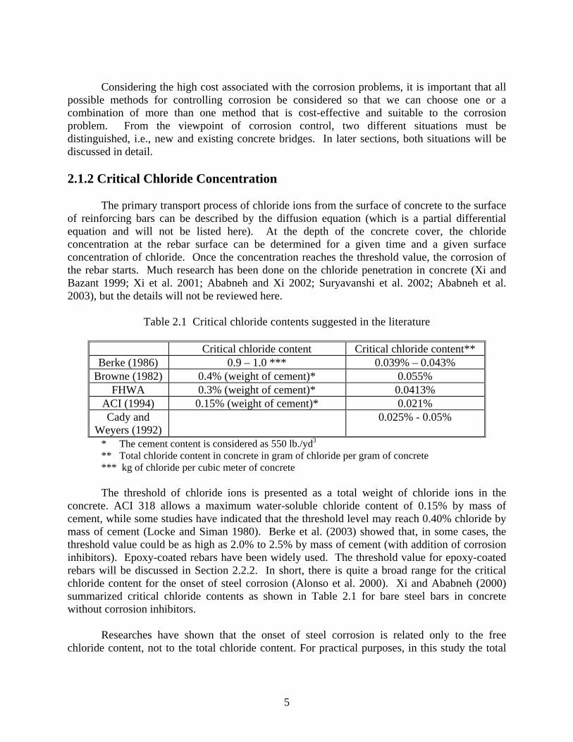
Table 2.1 Critical chloride contents suggested in the literature
Critical chloride content Critical chloride content** Berke (1986) 0.9 – 1.0 *** 0.039% – 0.043%
Browne (1982) 0.4% (weight of cement)* 0.055% FHWA 0.3% (weight of cement)* 0.0413%
ACI (1994) 0.15% (weight of cement)* 0.021% Cady and
Weyers (1992) 0.025% - 0.05%
* The cement content is considered as 550 lb./yd3
** Total chloride content in concrete in gram of chloride per gram of concrete *** kg of chloride per cubic meter of concrete
The threshold of chloride ions is presented as a total weight of chloride ions in the
concrete. ACI 318 allows a maximum water-soluble chloride content of 0.15% by mass of cement, while some studies have indicated that the threshold level may reach 0.40% chloride by mass of cement (Locke and Siman 1980). Berke et al. (2003) showed that, in some cases, the threshold value could be as high as 2.0% to 2.5% by mass of cement (with addition of corrosion inhibitors). Epoxy-coated rebars have been widely used. The threshold value for epoxy-coated rebars will be discussed in Section 2.2.2. In short, there is quite a broad range for the critical chloride content for the onset of steel corrosion (Alonso et al. 2000). Xi and Ababneh (2000) summarized critical chloride contents as shown in Table 2.1 for bare steel bars in concrete without corrosion inhibitors.
Researches have shown that the onset of steel corrosion is related only to the free
chloride content, not to the total chloride content. For practical purposes, in this study the total
5

chloride content will be used as critical chloride concentration based on the information provided in Table 2.1. 2.2 Corrosion Control in New Concrete Bridges
Many new bridges will experience severe environmental conditions during their service life. In order to build the concrete bridges that have high resistance against rebar corrosion, we need to make concrete that can survive severe weather conditions. We have to systematically use a combination of different measures, such as adequate concrete cover, good concrete quality, adequate corrosion inhibitors, and corrosion-resistant reinforcements.
2.2.1 Concrete Cover
(1) High Performance Concrete Concrete cover is the first line of defense for the corrosion protection. There are three important aspects that must be considered simultaneously: thickness, chloride permeability, and crack resistance. Concrete cover with high quality and adequate thickness helps to reduce the rate of penetration of chloride ions from the environment onto rebars, and thus prevent the corrosion of the rebar. Adequate depth of concrete cover can be determined by applying diffusion theories for chloride penetration into concrete. The cover depth should be designed such that the chloride ions accumulated on the surface of rebar do not exceed the critical concentration within a required time period. The requirement on the chloride penetration resistance must be combined with the construction tolerances to achieve a rational depth of cover specification. In the practice, the thickness of concrete cover is usually about two inches.
However, adequate concrete cover will not completely prevent reinforced concrete from experiencing corrosion damage, because most of concrete covers crack due to internal or external loads (including environmental and traffic loadings). One of the most comprehensive researches done on the performance of protection systems (Pfeifer et al., 1987) examined 11 different systems under saltwater attack and drying-rewetting cycles. Their results showed that the occurrence of a single crack significantly influences the behavior of rebar corrosion. When the cracks occur, the chloride ions can easily penetrate the concrete through the cracks. In addition, the local variations of concrete covers (in terms of thickness and density of the concrete across a structure) will result in non-uniform distribution of chloride at the depth of rebar, and thus create micro-cells (consisting of cathodes and anodes in a small local area). Therefore, other protective measures must be considered in addition to adequate concrete cover. High quality concrete is one of the most important aspects of corrosion control. Extensive reviews were given by Thompson and Lankard (1999), Hansen et al. (2001), and Xi et al. (2002) on the effects of concrete design parameters on crack resistance and chloride permeability, which will not be repeated here. Many state and local agencies, including CDOT, have developed various high performance concrete mix designs for application on bridge decks (Lane and Ozyildirim 1999; Xi et al. 2001).
6

(2) Testing Methods for High Performance Concrete
Although it is well accepted that chloride permeability and crack resistance of concrete are important durability properties related to steel corrosion, there has been a lack of reliable testing methods to evaluate the long-term properties of concrete (Whiting and Cady 1992; Hooton et al. 2000).
Two types of tests are currently used in the U.S. to measure the permeability of concrete, i.e., Chloride Ponding Test (AASHTO T259 and ASTM C1443-02) and Rapid Chloride Permeability Test (ASTM C 1202-97 and AASHTO T277 “Electrical Indication of Concrete’s Ability to Resist Chloride Ion Penetration”), the so-called RCPT. The former is believed to be more reliable, but needs more time (90 days) than the latter (about one day). In order to achieve the desired service life of 75 to 100 years, FHWA and TxDOT provide guidelines for maximum value of 1500 coulomb passed at 56 days for all high performance concrete mixes based on RCPT. It should be noted that if RCPT is used there is a major exception, as mentioned in ASTM 1202, when calcium nitrite is used as a corrosion inhibitor. Calcium nitrite raises the conductivity of pore fluid so much that it can raise significantly the values of RCPT test results even though chloride penetration resistance of the concrete is quite good.
In Europe, Canada, and the U.S. there are several standard testing methods for chloride
permeability of concrete (Hooton 2003): the classic diffusion cell test (Page et al. 1981); the immersion test based on Fick’s second law (NT BUILD 443 and ASTM C1556-03); the migration test method (NT BUILD 355); and the non-steady state test (NT BUILD 492).
Due to the fact that RCPT may lead to unreliable result, especially when certain mineral admixtures such as silica fume were included in the concrete mixture and when calcium nitrite (one type of inhibitors) or reinforcing steel was presented in the concrete specimen, a new method for predicting chloride ion penetration has recently been developed, called the new rapid migration test. The new rapid migration test is based on a test developed by Tang and Nilsson at Chalmers Technical University in Sweden (NT BUILD 355, see Tang and Nilsson 1993). Field trials of the rapid migration test have been conducted at TFHRC, Texas DOT, Ontario Ministry of Transportation, Virginia Transportation Research Council, and University of Toronto. All of these tests used concrete from batches that were mixed at TFHRC. The crack resistance test (the ring test, AASHTO PP34-98 “Standard Practice for Estimating the Crack Tendency of Concrete”) has been used for estimating the crack resistance of concrete. However, cracks that occur on the surface of a concrete ring due to drying shrinkage are often microcracks, which are very difficult to detect. The test results depend heavily on the experience of the observer and the equipment used in the test. Therefore, accurate determination of when the first cracking occurs remains an issue. 2.2.2 Alternative Reinforcements Concrete has very low tensile strength, and thus, it is impossible to keep concrete from cracking during the service life of concrete bridges. The concrete cracks could result from non-mechanical loads (thermal stress, shrinkage stress, creep, and attacks of aggressive chemicals) or external mechanical loads (traffic load, etc.). Once the crack occurs, chloride ions can easily
7

penetrate through the cracks to the rebar. Therefore, no matter how good the concrete quality is, the final line of defense against corrosion of rebar is the rebar itself. Currently, there are two alternatives to solve this problem (Wheat and Deshpande 2001): (1) The conventional mild steel can be coated with an effective barrier to prevent direct contact of steel with chloride, moisture, and oxygen; and (2) The reinforcement is made of corrosion-resistant materials. Currently, the first option may be the most economical one. (1) Rebars with Organic Coating
Epoxy-coated rebars (ECR) have been used since early the 1970’s with a successful performance record. There are some problems associated with ECR, such as damage to coating during transport and handling (known as holidays), and cracking on coating rising from the rebars at construction site that may reduce the effectiveness of ECR. Some measures have been suggested to alleviate these problems, such as bending the rebars before coating, using more support during the shipping process, and using padded bundling bands and nylon slings during loading and unloading.
One of the 5-year research projects from the Federal Highway Administration (FHWA) involved the testing of more than 40 types of newly developed coatings. The results showed that major corrosion damage is due to defects in coatings, which may be caused by insufficient thickness of the coating, tie wire marks, out-of-door storage etc. (McDonald et al., 1994; McDonald et al., 1995).
Figs. 2.1, 2.2, and 2.3 show ECRs at a construction site in Colorado in 2003. The ECRs
look like they are in good condition from a distance (Fig. 2.1). Figs. 2.2 and 2.3 are close views of the ECRs. One can clearly see that corrosion has already started in locations where the epoxy coating is damaged. It is very difficult to completely avoid damaging the epoxy coating.
Fig. 2.1 The appearance of epoxy-coated rebars from distance.
Fig. 2.2 A close view of the epoxy-coated rebars. Surface damages can be seen.
8

Fig. 2.3 A close view of the epoxy-coated rebars. Corrosion started on the locations with damaged coatings.
From research conducted by the FHWA, the following conclusions can be made (Virmani and Clemena 1998): • ECR has provided effective corrosion control for concrete bridge decks for up to 20 years.
No maintenance has been performed on thousands of bridge decks constructed with ECR. • A bridge deck in West Virginia had only 0.25-percent concrete delamination after 19 years of
service life. The largest delamination was centered at a construction joint and was not attributed to rebar corrosion.
• No evidence of corrosion has been found on 81 percent of the ECR segments extracted from deck cores.
• Some of the corrosion was observed on ECR segments in concrete where the chloride concentrations were below the corrosion threshold level. This corrosion was attributed to superficial corrosion that was already present on the rebars at the time of construction.
• Most of the corrosion was observed on ECR extracted from cracked concrete where chloride concentrations were high.
• In uncracked concrete where moisture levels were typically nominal, ECR tolerated higher concentrations of chloride. In fact, little or no corrosion was observed in uncracked concrete with chloride concentrations as high as 7.6 kg/m3 (12.8 lb/yd3) or 0.32% of mass of concrete assuming 2400 kg/m3 as the density of concrete.
• The data from field investigations indicated that a better resistance to corrosion was obtained when ECR was used in both mats of reinforcement instead of just the top mat.
On the other hand, a recent study by Michael Brown et al. (2003) presented some evidences that epoxy-coated rebars (ECR) and bare bars have about the same threshold value of chloride. After the corrosion process starts, the rust formed around steel is confined under epoxy coating for ECR, while for bare bars the rust spreads into cement paste matrix. They concluded that the corrosion service life extension attributable to ECR in bridge decks was approximately five years beyond that of bare bars. In Florida, application of epoxy-coated rebar for substructures has been stopped (Manning, 1996). This may be due to the fact that organic coating will never be able to protect
9

reinforcing steel in a hot, humid, salt contaminated environment such as in the Florida Keys where concrete stays wet continuously. This may not apply in the areas (such as in Colorado, Central US) where reinforced concrete structures are not exposed to continuous dampness.
In 2003, FHWA sponsored a study of epoxy-coated rebars. To date, the most preferred corrosion protection system in many states has been fusion-bonded epoxy-coated rebars. It has been used extensively in bridge decks for about 25 years (about 50,000 bridge decks with about 600 million square feet of deck surface) and its performance has been very satisfactory when exposed to deicer application for snow and ice removal. But the same ECR has had less success when both deicer (salt) and water had easy access to cracked concrete and/or exposed to the splash zone in a marine environment. A number of State DOT’s are constructing bridges in the marine environment using ECR in combination with calcium nitrite as a corrosion inhibitor (mixed into the fresh concrete) for the protection of damaged/bare areas of ECR, as a common sense approach. No independent laboratory study has been performed to verify that this multiple corrosion protection strategy has provided any added protection when concrete is cracked, or whether in fact it has increased the chloride threshold for corrosion initiation and ultimately decrease the ECR corrosion rate.
With ongoing research efforts to produce better ECRs, it is expected that highly corrosion resistant ECRs will be achieved in the future. At present, limited research is being performed to evaluate a multiple coating system where zinc is sprayed on the black bar prior to the application of fusion bonded epoxy coating. Similarly, another powder manufacturer is encapsulating corrosion inhibitors in to the beads and mixing in epoxy powders to coat rebars for better corrosion performance. (2) Steel Bars with Metallic Coating and Cladding
Metallic coating has been successfully used to prevent the corrosion in applications other than reinforced concrete structures. It has raised the hope that metallic coatings will have similar success on reinforced concrete structures. Metallic coatings can be classified into two categories: sacrificial and non-sacrificial (noble). The sacrificial protection is used by coating rebars with metal zinc that has more negative potentials than iron. When the coating is broken, a galvanic cell is formed whereby the coating is slowly sacrificed (corroded). Noble metals such as copper and nickel can also be coated on rebar, however, the protection exists only when the coating remains intact. Once the coating is damaged, the exposed steel is anodic to the coating. • Galvanized Rebars Zinc-coated, or galvanized, bars are produced by a hot-dip process. The field experience of the performance of galvanized bars in concrete structures exposed to deicing salts or seawater is conflicting. In general, for new concrete decks with concrete cover at least 51 mm and water cement ratio of 0.45, the use of galvanized bars may add five more years to the service life of bridge structures.
• Stainless Steel-clad Rebars
10
The corrosion rate of this type of rebar is about 800 times lower than black steel bars. The rebar has been used in Europe, especially in the UK, but has a limited use in the U.S. due to the high cost. The initial cost to build bridges using stainless steel-clad rebars is quite high, however, the maintenance and repair cost would be much less. Several state DOTs are currently working on research projects using clad stainless steel bars: Kentucky: clad stainless steel & MMFX Steel for deck slab Missouri: clad stainless steel rebars Oklahoma: clad stainless steel rebars
• Copper-clad Rebars
This is the most recently developed metallic coating for rebars. The results of laboratory tests showed exceptional resistant against corrosion. It is expected that this type of rebar will become a cost-effective option for corrosion protection systems, because the cost of copper-clad rebars could be under $1.20/kg ($0.54/lb). However, further study is still needed before the copper-clad rebar can be used in real concrete bridge structures. (3) Alternative Solid Bars • Advanced Carbon- and Glass-Fiber Reinforced Polymer Bars (CFRP and GFRP bars)
Using CFRP and GFRP as rebars would completely solve the problem of corrosion. The FRP rebars have strength up to 6-10 times of black steel and weight up to one fifth of the steel. Again, the use of these rebars is still limited due to high cost. Many state and local agencies are using the composite bars to build bridges (The complete list will not be listed here). CDOT has had three research projects on this topic sponsored by FHWA/IBRC program. The first project focused on the applications of CFRP and GFRP bars as reinforcement in bridge decks. The composite bars were used to build bridge decks in the I-225 & Parker Rd. interchange. The second project used FRP shapes (panels) to build a bridge in O'Fallon Park, Denver, Colorado. The third project is using FRP sheets to wrap up (to strengthening) a historical arch bridge in Castlewood canyon. • Stainless steel bars Instead of using stainless steel as a coating or cladding on black steel, solid stainless steel as reinforcements have been used in bridge decks (Concrete Society 1998). There are four major types of stainless steel that are distinguished by their microstructure and possess different characteristics: austenitic, ferritic, martensitic, and duplex stainless steels. Only austenitic and duplex stainless steels are recommended for use as reinforcement to concrete because of their high corrosion resistance. Austenitic stainless steels have chromium and nickel as the main elements alloyed with the iron, whereas duplex steels have high chromium and low nickel contents. Stainless steel reinforcement is specified in ASTM A955M-96 (Standard specification for deformed and plain stainless steel bars for concrete reinforcement), which covers reinforcement
11
in a wide range of alloys (ferritic, martensitic, austenitic, and duplex). Reinforcing bars are specified also in ASTM A276-95 (Specification for stainless steel bars and shapes). Austenitic stainless steels are identified as 300 series types. In particular, AISI 316LN and AISI 316L are often used, and typical duplex stainless steels are types 2205 and 329. Several projects were conducted in the UK and in Canada. The first application of solid stainless steel reinforcement in the U.S. was type 304 stainless steel bars used in a bridge deck carrying the Interstate Highway I-696 near Detroit, Michigan in 1985. Several DOTs are currently working on research projects using this type of rebars (e.g., Montana: solid stainless steel rebars). • MMFX microcomposite steel
MMFX steel has a high corrosion resistance as a result of the patented and proprietary steel microstructure that is formed during its production (Thomas 1996). This unique physical feature minimizes the formation of micro galvanic cells in the steel structure, thereby minimizing corrosion initiation. Therefore, MMFX's steels are highly corrosion resistant and are equal or better than existing steels in their mechanical properties (yield strength, energy absorption, toughness, brittleness, ductility, weldability, hardness and formability). The manufacturer of the steel currently has two proprietary types of steel, Dual Phase Steel and Microcomposite Steel. Dual Phase Steel is a microcomposite ferritic / martensitic low carbon steel that has been rolled and quenched in a controlled manner. This steel has been proven to exhibit superior corrosion resistance in reinforced concrete applications, as well as superior mechanical properties compared to existing rebar (i.e., A615) Microcomposite Steel is a steel that exhibits similar microstructure characteristics, but without ferrite. It differs from Dual Phase Steel in material composition and does not require quenching to produce the prerequisite microstructure for its corrosion resistance and mechanical properties. Several state DOTs have ongoing projects using the new steel Florida: FRP composites & MMFX steel for deck slab Iowa: MMFX steel for deck slab Kentucky: clad stainless steel & MMFX steel for deck slab South Dakota: MMFX steel for decks and pavements 2.2.3 Corrosion Inhibiting Admixtures Corrosion inhibitors are chemical substances that are added to concrete in small concentrations to reduce or completely stop corrosion. There are many different corrosion inhibitors available on the market, and they can be classified into three categories:
12

(1) Anodic Inhibitors Anodic inhibitors function as passivators on the rebar by forming protective films on
anodic surfaces or by absorption on the metal. Chromates, nitrites, molybdates, alkali phosphates, silicates, and carbonate are examples of anodic inhibitors. Certain anodic inhibitors, i.e., nitrites must be applied in large doses because an insufficient quantity of inhibitors will fail to treat all of the anodic sites and pitting corrosion may occur due to the high cathode to anode ratio (Fadayomi, 1997). The most widely used anodic inhibitor in the U.S. is calcium nitrate. The dosage of calcium nitrites must be determined based on the expected chloride loading during the structure’s service life. Actual dosages range from two to six gallons per cubic yard. Nitrite is one of components in an acceleration admixture. Therefore, the use of nitrite will shorten the setting time of fresh concrete mix. Retarders are frequently used to balance the setting time, especially when large dosages of calcium nitrites are used.
(2) Cathodic Inhibitors
Cathodic inhibitors function by forming an insoluble protective film on alkaline cathodic
surfaces through the production of a compound that is insoluble at high pH levels. This protective film prevents the reaction between cathodic and oxygen. Zinc, salts of antimony, magnesium, manganese, and nickel are examples of cathodic inhibitors. These inhibitors are generally less effective than the anodic inhibitors.
(3) Organic Inhibitors
This type of inhibitor is used such that the corrosion at the anodes and cathodes are simultaneously inhibited. These types of inhibitors include amines, ester, and sulfonates. These inhibitors function by forming a protective barrier (monomolecular film) between the rebar and the chloride ions, which prevents the reaction between the iron and chloride ions. In using these inhibitors, we do not need to know the estimate of chloride loading for the structure because the way they are functioning (form protective barrier without competing reaction with chloride ions). The dosage is one gallon per cubic yard, which should be added during batching. It is interesting to note that these organic inhibitors function well in cracked concrete in laboratory tests. The protective barrier formed keeps functioning even when chloride ions penetrate directly to rebar through cracks. (4) Field study of corrosion inhibitors in other states The FHWA investigated the effectiveness of corrosion inhibiting admixtures in outdoor exposure of reinforced concrete slabs (Virmani et al 1983). The reinforcement was evaluated by measuring the macrocell corrosion current, half-cell potential, driving voltage, concrete electrical resistivity, and visual inspection. The study concluded that calcium nitrite is effective in reducing the corrosion rate in black steel bar at chloride-to-nitrite ratios of 1.79 or less. Note that the effectiveness of corrosion protection provided by calcium nitrite can be measured by the ratio of chloride ions over nitrite ions, which should be kept below 1.0 for the entire life of the structure. After seven years of observation, the maximum ratio of chloride to nitrite ions necessary to reduce the rate of corrosion in steel was reduced to 0.90.
13

Another study of corrosion inhibitor admixtures was published by the Virginia
Transportation Research Council in 1999 (Zemajatis et al.). This study indicates that calcium nitrite is effective in reducing the rate of corrosion, when the concentration of chloride ions does not exceed the concentration of nitrite ions at reinforcing steel level. At a chloride to nitrite ratio near 1.0, the calcium nitrite appears to reduce the rate of corrosion by an order of magnitude compared to control slabs without calcium nitrite. It simply means that if one expects 15 lbs of chloride per cubic yard accumulation at the top mat level for the designed corrosion free service life, one has to add about seven gallons of corrosion inhibitor (i.e., DCI) for each cubic yard of concrete. This amount is slightly higher than the manufacturer’s recommended dosage of five gallons for 15 lbs of chloride per cubic yard. The higher quantity is based on the seven year research study where the chlorides were added along with nitrite ions at the time of slab fabrication.
Most of the studies mentioned above were conducted in a laboratory (outdoor or indoor) environment. No major documented reports for field performance of corrosion inhibitor admixtures have been published. This is due to the fact that most corrosion inhibitor admixtures have been introduced in recent years, except DCI (Darex Corrosion Inhibitor, which is an aqueous solution containing approximately 30 percent calcium nitrite), therefore no adequate field performance has been recorded. 2.3 Corrosion Control for Existing Concrete Bridges There are several remedial methods that can be used in the rehabilitation of existing concrete bridge structures that are damaged by corrosion of steel bars due to chloride ingress or carbonation. Based on the nature of repair procedures, the rehabilitation methods can be classified into two types, i.e., conventional and unconventional rehabilitation methods. 2.3.1 Conventional Rehabilitation Methods
Conventional rehabilitation methods are carried out by providing barrier on the surface of damaged concrete to protect the concrete from further ingress of chloride ions, moisture, and oxygen. There are several rehabilitation methods available (Sprinkel et al. 1993; Whiting et al. 1999; Zollinger et al. 2001), which can be grouped as two categories: removal of distressed concrete and without concrete removal. In the first category, portions of concrete section need to be removed (Vorster et al. 1992) and replaced with some types of patching material such as low slump concrete, latex modified concrete, or silica fume concrete. Sealers may be applied on the surface of the new concrete. This type of repair method for corrosion damage should be used when significant amounts of concrete have cracked or spalled and repairs are necessary for safety considerations or continuity of operations. In the second category, no concrete removal is performed; overlay membranes and sealers are applied on the surface of the concrete. This type of repair method for corrosion damage should be used, for instance, on structures in harsh environments, either as an initial treatment or when the structure has been exposed for some time to the environment, but no significant distress has occurred.
14

(1) Membranes and sealers
Membranes and sealers help prevent further ingress of chloride ions. Some examples of membranes are urethanes, neoprenes, and epoxies. They are usually applied in multiple layers and have the ability to bridge cracks in concrete. Since there are many different products, the performance of these methods can vary significantly (Al-Qadi et al. 1992; Whiting et al. 1993; Whiting et al. 1999). Some products are solvent based, which may not be suitable for some areas. Most sealers are not suitable for sites where abrasion occurs. It also should be noted that the effectiveness of these methods decreases over time. Thus, they must be reapplied after a certain period. The length of the period varies, and it depends on the performance of the membranes. The following are some membranes and sealers used in research and repair projects: • Linseed oil • A two-component, marine-grade epoxy coating utilizing an epichlorohydrin/bisphenol A
base resin and polyaliphatic amine curing agent • 40% solution of an alkyltrialkoxy silane (ATS) in isopropanol • 20% solution of an oligomeric alkyl-alkoxy siloxane (AAS) in a blend of naphtha and
diacetone • Two-component clear penetrating sealer consisting of a primer containing a 20% solution of
an oligomeric alkoxy siloxane/silane in mineral spirits and a topcoat consisting of a solution of methyl methacrylate in xylene (AS/MM)
Some highway departments have had trouble with membrane debonding and stripping.
These problems normally require the removal and replacement of the membrane in ten years or less, depending on both the volume of traffic and the environment. Some membranes deteriorate after about 15 years of service due to traffic stresses and aging. One of the causes of debonding is due to water that is trapped on top of the membrane. Freezing and thawing, along with pressure from traffic load, weaken the bottom part of the asphalt overlay and the bond between the asphalt overlay and membrane (Khossrow and Hawkins, 1998). One of the examples of this problem was discovered during the inspection performed in this study on one of the bridges on I-70 EB over Moss St. near Golden, Colorado (see Section 5.3). To prevent the problem, proper drainage should be provided so that the water can drain quickly from the deck, and a seepage drain should be provided at low points to prevent water from sitting on top of the membrane (Manning, 1995). Careful installation of membrane will prevent such problems.
In the period between 1967 and 1974, Kansas (K-TRANS, 2000) installed waterproofing
membranes on nearly 10,000 m2 of salt-contaminated bridge decks. These membranes have performed well, with little maintenance. Asphalt riding surface have ranged from satisfactory, with some cracking, to excellent. This may be due to the fact that the rate of evaporation is higher than the rate of precipitation in Kansas, which may be a factor in the good performance of these membranes.
In recent years, penetration sealants have been used on bridge decks for corrosion
protection. Attanayaka et al. (2002) evaluated the potential durability gained by the use of penetrating sealants on concrete bridge decks. The primary conclusion of the study was that penetrating sealants are an effective means of protecting concrete bridge decks. Properties and
15

the use of silane, siloxane, and high molecular weight methacrylate sealers were discussed. The use of high molecular weight methacrylate is recommended based on its extensive applications in the field. Silane and siloxane penetrating sealers can be used on new decks. High molecular weight methacrylate (HMWM) in conjunction with silane sealers can be used on cracked decks. If the maximum crack width is less than 0.002-inches, silane sealers are adequate to seal the deck. When the crack width is between 0.002- and 0.08-inches, silane and HMWM sealers can be applied provided an adequate drying period is maintained between silane and HMWM applications.
(2) Low-slump concrete (dense concrete)
Low-slump concrete is achieved by using a high content of cement (typically 800 pounds per cubic yard) and low water cement ratio (below 0.35). To make it more workable, HRWR is usually added. This kind of concrete could provide low permeability of concrete provided that the concrete is well consolidated. However, its performance is not as good as latex modified concrete or silica fume concrete. This is probably due to the limited workability, which may make it difficult to place and consolidate. The advantage of this method over the others is its low cost.
(3) Latex-modified concrete
A latex-modified concrete is formed by adding liquid styrene-butadiene latex into a
conventional concrete mix. Typically, the latex-modified concrete mix contains 658 pounds of cement per cubic yard, 15% of latex solid by weight of cement, and a water cement ratio of 0.35. The latex modifies the pore structures of concrete, which result in a low permeability concrete.
The disadvantage of this method is that there are some cracking problems associated with
this method. Some state agencies suggested casting the concrete in the evening or night to reduce the risk of cracking. Another method is to add micro-fibers to change the crack pattern from several large cracks to many microcracks. (4) Silica fume concrete
In concrete mix, silica fume reacts with calcium hydroxide (CH) in hydrated Portland cement paste to form calcium-silicate-hydrates (C-S-H), which reduces the concrete permeability significantly. The typical silica fume concrete mix contains 658 pounds of cement per cubic yard, 8% to 10% of silica fume by weight of cement, and a water to cementitious ratio of less than 0.40. HRWR is usually added to reach 6 to 8 inches of slump. CDOT used this type of concrete for deck overlay. The mix is called Class SF.
The problem with this type of concrete is the cracking due to plastic shrinkage. Good
casting and curing procedures could reduce this problem. In recent years, CDOT improved its practice on deck concrete and overlay concrete. See
Chapter 3 for details.
16
2.3.2 Unconventional Rehabilitation Methods These methods involve the application of an electrochemical process to control the electron flow in the rebars to halt the metal loss (cathodic protection) or to modify concrete conditions to make it less corrosive (Electrochemical Chloride Extraction (ECE) and Electrochemical Realkanization (ER)).
(1) Cathodic Protection
Cathodic protection can be achieved, in principle, by applying direct current through the concrete from an external anode usually laid on the concrete surface. The anode is connected to a positive terminal of a low voltage direct current source (10 mA/m2), to the rebars, which act as cathodes, and to a negative terminal.
Cathodic protection systems provide highway agencies the option of rehabilitating, rather
than replacing the concrete structural components damaged by corrosion, which could possibly lead to significant cost savings. In recent years, the cost of rehabilitating distressed concrete due to corrosion has been dropped as low as one-half, making an already cost-effective technology even more affordable. The main reason for the price drop is that cathodic protection systems have become simpler and more mature. The systems no longer need extensive monitoring equipment to ensure that the protection system works properly. In addition, contractors have become more familiar with the technology and also more efficient in designing and installing the systems.
There are many different cathodic protection systems on the market (ElTech 1993a; Bennett et al. 1993). For concrete decks, the application of impressed-current cathodic protection using titanium mesh anodes provides the best performance among all types of cathodic protection systems.
Because of vertical or angle surfaces, the most appropriate cathodic protection systems for bridge substructures are arc- or flame-sprayed zinc coating and also the water-based conductive paints. Another suitable system for substructures is aluminum alloy anode, which can provide higher current than zinc anode. To meet a variety of environmental or climate conditions, recent studies suggest combining aluminum, zinc, and indium to obtain the optimal composition.
For rehabilitation of prestressed concrete members, some cautions must be made, because of the bond losses and hydrogen embrittlement associated with cathodic protection in prestressed concrete. The use of cathodic protection as a rehabilitation method has been limited. However, recent studies showed that these problems can be reduced or eliminated by effective monitoring and controlling using remotely operated hardware and software. There are many applications of cathodic protection anode systems in other states. In October 1988, five different impressed cathodic protection systems (three on the deck and two on the sidewalk and supporting bent) were installed in Big Spring, Texas (Nash et al., 1994). The study also shows the cost effectiveness of each cathodic protection system compared to deck
17

maintenance or replacement without using cathodic protection. It was concluded in this study that the cathodic protection system would not generally be a cost effective method for maintaining or protecting bridge decks. A study was also performed to determine the effectiveness of an intermittent protection system using solar power (Kessler et. al., 1998). The idea was that it would be cost effective if the power supply of the system was not continuous. This system provided protection when it was exposed to the sunlight. The study concluded that depolarization occurred during the periods of no cathodic protection. However, leveling polarization can be maintained when sufficient current is supplied to the system. In addition to this, calibration of the system when exposed to maximum sunlight needs to be taken to avoid overprotection from increasing current, and measurements should also be taken to impede the depolarization of the system during times of no sunlight.
There were two new FHWA reports on the cathodic protection of Bridge Concrete Members (FHWA-RD-98-075, & FHWA-RD-98-058). In these reports, it was considered that only the cathodic protection method either alone or in combination with other repair methods, is capable of stopping the corrosion of steel reinforcement in chloride contaminated concrete. In the second report, the sacrificial cathodic protection method was evaluated. It was found that the aluminum-zinc alloy provided a higher current than Zinc anode and that Zinc anode was not effective when the concrete was not moist. (2) Electrochemical Realkalization (ER)
Realkalization treatment has been used for repairing concrete with severe carbonation in concrete cover. The principle of the method is based on the mass transfer of ions in an electrolyte solution due to the influence of an external electrical field. The technique involves the application of a high intensity DC current for a short period, typically a few days, between steel reinforcements acting as a cathode and an extended anode placed in an external electrolyte which is in contact to the surface of the concrete. The aim of the treatment is to re-establish high alkalinity around the steel reinforcement by promoting the production of hydroxyl ions at the steel cathode and inward migration of alkali ions from the external electrolyte. In order to achieve this aim, alkali solutions such as sodium carbonate have been commonly used as the external electrolyte.
In the practice, the preparation of ER is similar to cathodic protection systems, but cathodic protection is a permanent system, and ER is a temporary measure (3 to 5 days). The ER is achieved by applying a voltage between an anode and cathode (Rebar). Under the passage of an electrical current (up to 1 Am-2), the electrolyte, an alkaline solution is transported into the concrete toward the rebars. At the same time, the electrochemical production of hydroxyl ions increases the alkalinity on the surface of rebars, repassivates rebars, and prevents the corrosion to occur. This method can raise the alkalinity of concrete to a pH greater than 10.5. Fig. 2.4 shows a regular realkalization system.
In recent years, more attention has been paid to the damage of concrete due to alkali-
silica reaction (ASR), realkalization increases the alkalinity of the cement paste, and thus may
18
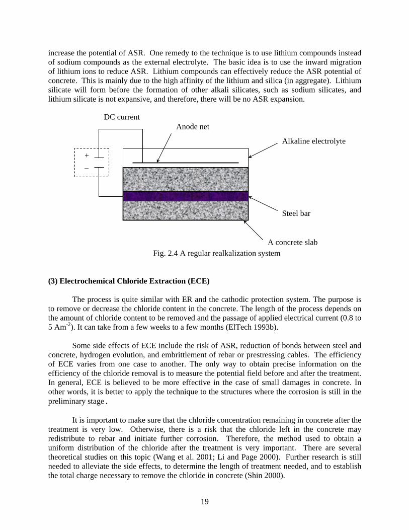
increase the potential of ASR. One remedy to the technique is to use lithium compounds instead of sodium compounds as the external electrolyte. The basic idea is to use the inward migration of lithium ions to reduce ASR. Lithium compounds can effectively reduce the ASR potential of concrete. This is mainly due to the high affinity of the lithium and silica (in aggregate). Lithium silicate will form before the formation of other alkali silicates, such as sodium silicates, and lithium silicate is not expansive, and therefore, there will be no ASR expansion.
Fig. 2.4 A regular realkalization system
A concrete slab
Steel bar
+ _
DC current Anode net
Alkaline electrolyte
(3) Electrochemical Chloride Extraction (ECE)
The process is quite similar with ER and the cathodic protection system. The purpose is
to remove or decrease the chloride content in the concrete. The length of the process depends on the amount of chloride content to be removed and the passage of applied electrical current (0.8 to 5 Am-2). It can take from a few weeks to a few months (ElTech 1993b).
Some side effects of ECE include the risk of ASR, reduction of bonds between steel and concrete, hydrogen evolution, and embrittlement of rebar or prestressing cables. The efficiency of ECE varies from one case to another. The only way to obtain precise information on the efficiency of the chloride removal is to measure the potential field before and after the treatment. In general, ECE is believed to be more effective in the case of small damages in concrete. In other words, it is better to apply the technique to the structures where the corrosion is still in the preliminary stage.
It is important to make sure that the chloride concentration remaining in concrete after the treatment is very low. Otherwise, there is a risk that the chloride left in the concrete may redistribute to rebar and initiate further corrosion. Therefore, the method used to obtain a uniform distribution of the chloride after the treatment is very important. There are several theoretical studies on this topic (Wang et al. 2001; Li and Page 2000). Further research is still needed to alleviate the side effects, to determine the length of treatment needed, and to establish the total charge necessary to remove the chloride in concrete (Shin 2000).
19

3. Current CDOT Practice Regarding Corrosion Protection
Over the years, CDOT applied several routine measures to prevent corrosion of the rebar in concrete including quality and durable concrete, a thick cover of concrete cover over steel, epoxy-coated rebars, waterproofing membrane covered by an asphalt overlay, sealers, and effective drainage systems. Region 6 has been topping the deck with two inches of silica fume concrete where a bare concrete deck is desired. Silica fume concrete has a very low permeability, which slows the penetration of chloride to the rebar. In addition to the routine procedures, some experimental measures were also taken such as corrosion inhibitors (calcium nitrite corrosion inhibitor) and cathodic protection systems.
The following is a brief list of CDOT and FHWA guidelines, specifications, and memorandum for controlling the steel corrosion problem in Colorado bridge structures.
• CDOT Spec. 515 standard specifications for construction of waterproofing membranes. • CDOT Spec. 709 for epoxy coating • CDOT Spec. 602 for steel. • CDOT Memo-27 on replaceable bridge decks. • FHWA Technical note on corrosion inhibitors. • FHWA Technical note on epoxy-coated rebars. • Revision of CDOT 519 on epoxy resin injection. • Revision of CDOT 515 on concrete sealer. • Revision of CDOT 202 on sandblasting reinforcing steel. • Revision of CDOT 202 on concrete removal. • CDOT Memo-10 on corrosion inhibitors in concrete. • CDOT Memo-2000 on bridge deck cover and overlay thickness.
The following is a brief summary on CDOT’s routine and experimental measures used for corrosion protection of new and existing reinforced concrete bridges. 3.1 Quality and Durable Concrete CDOT has been using compressive strength as the main control parameter for concrete for many years. Recently, two studies were completed on concrete mix designs used in Colorado for bridge decks (Xi et al. 2001; Xi et al. 2003). Based on the results of the two studies, rapid chloride permeability and cracking resistance have been included in the latest CDOT specifications for quality control on durability of concrete (more details are given in CDOT Section 601, Classes H and HT). In the specification, the rapid chloride permeability should be below 2000 Coulomb and cracking should not occur in less than 14 days.
According to the CDOT Memo on replaceable bridge decks, when a replaceable deck is impractical, supplemental corrosion protection measures should be considered to extend the life of the bridge deck either through waterproofing membrane or concrete overlay.
20

3.2 Concrete Cover over Reinforcing Steel Research has generally concluded that covers of 1¾ in. or more decrease the risk of corrosion. To assure a minimum cover of 1¾ in., an extra amount of ½ in. should be added to allow construction tolerances, resulting in a cover of 2¼ in. Colorado requires a minimum of 2½ in. clear cover to the top mat of reinforcing steel in bridge decks. For bare concrete deck slabs with a mechanical saw cut finish, the minimum cover to the top layer of reinforcing steel should be 3 in. For concrete decks with asphalt overlay, the thickness can be reduced to 2.5 in. (see CDOT Memo-2000 on bridge deck cover and overlay thickness).
Fig. 3.1 Castlewood Canyon Bridge Fig. 3.2 Repair corrosion damage on the arch
Fig. 3.1 shows an ongoing project at Castlewood Canyon Bridge. Severe corrosion
damage in the reinforced concrete arch was caused by poor concrete quality. A major portion of concrete cover was removed and replaced by shotcrete with corrosion inhibitors (see Fig. 3.2). The arch was then wrapped by carbon fiber reinforced polymer sheets. 3.3 Waterproofing Membrane with Asphalt Overlays The waterproof membrane and asphalt overlay are principle protective systems for bridge decks. The lifespan of bridge decks can exceed 50 years if asphalt overlay with membrane are used properly. However, both membranes and asphalt overlay deteriorate over time faster than the deterioration of concrete decks. Frequent maintenance work is needed. It is reasonable to assume that a preventive maintenance approach may need to be initiated to avoid breakdown in the system’s waterproofing effectiveness. The breakdown of the membrane could go undetected because it is usually covered by the asphalt overlay. CDOT Spec. 515.01 to 515.04 describes the application of waterproofing membrane.
Jeff Anderson from CDOT’s Staff Bridge indicated that many of Colorado’s bridges with waterproofing membranes look as new today as they did thirty years ago when they were first constructed, while bridges without membranes are showing serious contamination and deterioration within ten years after being constructed. Similarly, a multi-year study in Canada
21

concluded that the most effective approach to prolong the life of a bridge is to use a waterproofing membrane with an asphalt overlay.
Another CDOT Engineer made the following comments: It has been my experience that all concrete decks crack to some degree. The elements that destroy bridges, whether it is the bridge decks, pier caps, pier columns, abutments etc., is water and salts. Canada did a multi-year study where they concluded that the most effective measure we can take to prolong the life of a bridge, is to add a waterproofing membrane with an asphalt overlay. Their findings are confirmed by our experience with our own bridges. Many of the bridges with waterproofing membranes look as new today as they did thirty years ago when they were first constructed. Bridges without membranes are showing serious contamination and deterioration within ten years of being constructed. Water dripping on pier caps and abutments is the primary cause of deterioration in our abutments, pier caps and pier columns. Bridges that are designed without joints, or at least with the joints at the back of the approach slabs, will last a great deal longer than the bridges with expansion joints located over the substructure elements. This fact is confirmed every day by the bridge inspection program.
3.4 Epoxy-Coated Rebar (ECR) Black steel and ECR are the only types of reinforcements that have been widely used in bridge construction in Colorado. No other alternatives of reinforcements have been reported in Colorado. CDOT Spec. 602 and Spec. 709 are for black steel and for epoxy coating
Epoxy coatings (often referred to as powders or fusion bonded coatings) are 100 percent solid dry powders. These epoxy dry powders are electrostatically sprayed over cleaned, preheated rebar substrate to provide tough impermeable coatings. These coatings achieve their toughness and adhesion to the substrate as a result of a chemical reaction initiated by heat. For rebar epoxy coatings applications, epoxy powders are thermosetting materials and hence their physical properties, performances, and appearances do not change readily with changes in temperature. This epoxy coating over a steel rebar is the physical barrier between aggressive chloride ions (permeating through the concrete cover) and the bare rebar steel interface. Based on some systematic studies by FHWA, a FHWA Technical Note on ECRs was published. It states that the overall condition of the bridge decks (with ECR) is considered to be good. Deck cracking did not appear to be related to corrosion. Very few of the decks had any delaminations or spalls associated with the ECR. Any delaminations or spalls that were associated with corrosion of ECR were small and generally isolated. The chloride concentration at the rebar level was generally at or above the threshold for initiating corrosion in black steel. The ECR did not appear to perform as well in cracked concrete as uncracked concrete. Corrosion was observed on ECR segments extracted from locations of heavy cracking, shallow concrete cover, high concrete permeability, and high chloride concentrations. Reduced adhesion and softening of the coating also occurred as a result of prolonged exposure to a moist environment. The number of defects in the epoxy coating had a strong influence on the adhesion
22

and performance of ECR. There was no evidence of significant premature concrete deterioration that could be attributed to corrosion of the ECR. The use of adequate, good quality concrete cover; adequate inspection; finishing; and curing of the concrete; and the use of ECR have provided effective corrosion protection for R/C bridge decks since 1975. 3.5 Corrosion Inhibitors
There are two technical notes that are related to corrosion inhibitors: FHWA’s Technical note on corrosion inhibitors, and CDOT’s Memo-10 on corrosion inhibitors in concrete. In the FHWA technical note, three major commercially available corrosion inhibitors are described in detail, namely Darex Corrosion Inhibitor (DCI, manufactured by W.R. Grace and Co.), Rheocrete 222+ (produced by Master Builders), and Ferrogard 901 (developed by Sikka Corporation). CDOT engineers do not use these recommendations because of a lack of a method to predict the chloride level at the surface of steel rebars. Also, CDOT has no specific policy for the use of corrosion inhibitors.
W.R. Grace performed a field study for CDOT in order to evaluate the effectiveness of
the calcium nitrite corrosion inhibitors. In the project, the corrosion rate and corrosion potential of steel reinforcement in the Kettle Creek Bridge, Rt 83, Colorado Springs, CO, were measured using probes placed at eight different locations in the deck. The corrosion rate was measured using a technique called linear polarization. The concrete used to construct the north bound deck contained 3 gal/yd3 (15 L/m3) of DCI (a type of inhibitor containing mainly calcium nitrites). Four-year testing on the bridge showed that the corrosion rate for steel reinforcement in concrete with DCI is decreasing with time. The inspection was conducted again in 2002 to compare the effectiveness of ECR and corrosion inhibitor. The complete analysis can be seen in Chapter 5 of this report. The FHWA and CDOT technical notes show that penetrating corrosion inhibitors can be used on finished surfaces of existing concrete or on cut surfaces of existing concrete prior to placement of new concrete (like a sealer). This type of inhibitor is very useful for the corrosion problems of bridge columns. 3.6 Cathodic Protection Systems
CDOT used the impressed current cathodic protection system on many construction
projects on an experimental basis. In 1997, CDOT had a design build project on I-70 that included cathodic Protection on 8 Bridges. The Project was IR(CX) 070-4(143) subaccount 90023. The Bridges were as follows: F-18-AQ Eastbound MP 293.618 F-18-AP Westbound MP 293.619 F-18-E Eastbound MP 294.702 F-18-C Westbound MP 294.703
23

F-18-AS Eastbound MP 297.322 F-18-AR Westbound MP 297.323 F-18-AV Eastbound MP 299.328 F-18-AT Westbound MP 299-329
In the project, an AASHTO Provisional Standard MP5-95 or alternatively AASHTO-AGC-ARTBA was used (i.e., Joint Cooperative Committee Task Force Report 29 "Guide Specification for Cathodic Protection of Concrete Bridge Decks").
The 46th Avenue Viaduct (E-17-FX) between Brighton Blvd. and Colorado Blvd. was constructed in 1966, and its first rehab was in 1980. In 1997, the structure was rehabilitated again using sprayed zinc sacrificial anode protection at the hinge joints in addition to patching and the use of surface treatment with calcium nitrite prior to the zinc spray. The impressed current will fall when the concrete is not moist, but the corrosion rates will also fall due to increased resistance of the concrete. The lower part of the columns was also treated with corrosion inhibitor, possibly calcium nitrite.
Fig. 3.3 The Galvashield cathodic protection system installed in SH 85 SB in Greeley, Colorado.
Fig. 3.4 A close view of the Galvashield cathodic protection system.
In 2001, another type of sacrificial cathodic protection system was installed in a bridge
on HWY 85 SB in Greeley. Fig. 3.3 shows the installation of the cathodic protection system, and Fig. 3.4 shows a close look of the system installed in the concrete bridge decks. Since it is a new technology, the effectiveness of this type of cathodic protection is not yet known. 3.7 Use of FRP to Replace Steel Bars
Carbon FRP and Glass FRP bars were used in 2001 for bridge decks in the I-225 & Parker Interchange project (Denver, Colorado). CFRP was used for prestressing in the bridge decks and GFRP was used for reinforcement. Fig. 3.5 shows the bridge under construction and
24

Fig. 3.6 shows the prestressing process using CFRP. In this project, CFRP was found to be difficult to handle, required special chucks for stressing, and was very expensive.
Fig. 3.5 I-225 & Parker Interchange project Fig. 3.6 Prestressing bridge decks using CFRP
3.8 100% FRP Decks GFRP was used to build bridge decks for the O’Fallon park project (Denver, Colorado) in 2003. The performance of the decks were monitored by fiber optic sensors. Fig. 3.7 shows the bridge under construction. The GFRP bridge decks were installed. Fig. 3.8 shows the construction process of the GFRP panels. GFRP panels showed promise as the panels were easily installed. The question of this product is its durability with long-term truck traffic.
Fig. 3.7 Installation of GFRP decks in O’Fallon Park Bridge (Denver, Colorado).
Fig. 3.8 Construction of GFRP panels (on the top surface are wires for embedded fiber optic sensors).
25

3.9 Use of Sealers
Cracks often develop following the grooving of bridge decks. It is required in CDOT’s construction specifications (Revision of CDOT 515.05 on concrete sealer) to seal cracks wider than 0.035”. Very often, methyaculate is used for sealing cracks in concrete decks. It is reported that some new bridge decks are soaked with 0.25” of silane sealers. 3.10 Repair of Bridge Decks
The CDOT bridge inspectors inspect the bare deck (top surface under element 13 and bottom under 359, see Appendix A). Depending on the level of deterioration, different actions are recommended by the CDOT bridge inspectors to fix the problem. The CDOT Spec. Section 202 and its revisions describe the procedures for removing portions of the deteriorated bridge deck and for sandblasting of rebars prior to the repair of the deck. CDOT’s Spec. Section 519 describes the procedure for epoxy resin injection. Fig. 3.9 and Fig. 3.10 are the details for the repair procedures for concrete decks with steel girders and with concrete girders, respectively.
Fig. 3.9 Concrete deck (with steel girder) repair details
26

Fig. 3.10 Concrete deck (with concrete girder) repair details
27

4. Inspection Plan for Evaluating the Performance of Various Corrosion Protection Systems
It is very important for CDOT to inspect various routine and experimental corrosion protection measures to assess their performance with time and to estimate their remaining lives (needed for management of the bridges). There are general and specific guidelines for the inspection of the performance over time of different systems of corrosion protection measures (note that corrosion protection system could include use of several corrosion protection measures listed before). With reference and progressing time, performance data in terms of conditions of the bridge decks should be collected. These data could include profiles of chloride concentration obtained from cores, visual inspection of the bridge as often collected by CDOT inspectors, and surveys of delamination, potentials, and repaired areas. In many cases, the deterioration of the bridge could be related to the type of bridge structure, type of bridge deck drainage systems, type and location of joints, amount of deicing chemical applied per year, and geographical locations, all such information should be collected. Finally, the materials of different corrosion protection measures evolved over time so it is important to document the correct material information of any measure (e.g., materials of bridge deck concrete mix; of epoxy coating and waterproofing membranes).
Inspection report on a bridge structure should include: A. General Information of the bridge structure 1. Name, ID, year built, highway classification, location of the structure, and the climate at the
location of the structure. Description of the deck, substructure, and superstructure (i.e., type of girders, deck, pier and abutment structures, and type of joints, etc.). Initial widths of the bridge deck. Information on the type and amount of deicing slat applied over the years. Annual daily traffic.
2. Information on the corrosion protection measures used in the structure at time of construction, including the materials utilized in that measure (e.g., type of bridge concrete mix, thickness of cover, type and thickness of steel; information on epoxy coating used and type of proof water membrane).
3. Information on past rehabilitation construction projects including years of construction projects, methods and materials involved in the rehabilitation, %, location or distribution of repaired areas, any increases of the bridge deck width for widening purpose.
4. Information on regular and significant maintenance work (above normal) for the structure. 5. Information on the cost of the corrosion protections and its expected life in a format that
could be compared with other measures for the same situation. 6. CDOT Bridge inspection results for current and previous rating (in term of condition states)
of various elements of the bridge that could be used to study the performance of the corrosion protection measures with time (for bridge decks, joints, pier caps, and abutment seats). Obtain the inspection report (including inspection comments) of the structure at various times, especially at the time of any rehabilitation construction project. Focus on the results of Smart Flag 359 (See Appendix A) for the rating on corrosion damages.
28
All this information could be obtained from CDOT’s Bridge Management Database for bridges and from as constructed plans. B. Field Survey of the entire structure and testing of representative zone of the corrosion
zone 1. Photos and visual examination of all components of the bridge, indicating characteristics of
corrosion damages such as rust stain and efflorescence on concrete surface, concrete discoloration, cracks, and scaling and spalling of concrete cover within the selected zones on the bridge deck and pier caps. If a concrete deck has a high density of cracking, there may be a correlation between cracking density and chloride content. Document any sign of distress or corrosion of exposed steel, level of corrosion or damage (take samples of corroded steel if possible and analyze it in the lab).
2. Chain-dragging or similar techniques (like hammering) to detect delamination of concrete decks. Most of this test was applied to bare concrete decks. However, to some extent the chain dragging test was also applied to asphalt membrane overlay to detect the extent of the debonded/delamination of membrane with concrete deck and asphalt overlay.
3. Measured information on the bridge deck area that needs repair (delamination and spalling): % of repaired areas, their locations or distribution, class of damage (full depth or up to the cover), condition of the steel in the repaired areas (original and current effective diameters of the steel rebars).
4. In the case that any wiring system on steel bars is available (for measuring corrosion potential or Cathodic protection), examine the status of the system and read the corrosion current. Survey of potential should be considered for overall assessment of the corrosion health of the bridge.
5. Collect three to four concrete cores from the bridge deck, two from each bound (driving lane) and two from each shoulder lane. The diameter of concrete cores is four inches, and the length of the cores should be a minimum of four inches or deeper than the location of steel bars. The profiles of the total chloride content along different depths of the concrete cores from the exposed surface to the steel bar should be measured by drilling small holes in the concrete sample and analyzing the dust collected (similar to the 90-day ponding test, AASHTO T259 and AASHTO T260). Extract the steel bars from the concrete cores and clean the surface of the steel bars so that the extent of the corrosion (current and original diameter) can be examined (Section 7.7.3 of ASTM G1-88).
Specific inspection efforts may be needed for each corrosion protection system or measure and in many cases it is important to construct different system at the same structure for comparison purposes. For example, it is important to develop inspection plans to evaluate the effectiveness of using methyaculate for crack and joint sealing, and for application of silane on new bridge decks (soaked with 0.25”). Is the last technique effective for old structure instead of asphalt and membrane? Is it effective for a long time? In this case, we need to collect cores and see if there is silane on the top of the concrete cores. For cathodic protection systems, it is important to inspect on a regular basis if the system is still operational. Several items to consider during the inspection are the depolarization criteria and whether it is meeting this criteria. This is in addition to inspecting for other measures such as survey of delamination and others listed above.
29
It is also important to collect condition states of various elements (percentage of damaged areas) of bridges or results of tests, such as delamination or chloride concentration at various times. The analysis of performance data could be used to assess the performance of different corrosion protection measures with time and to estimate their remaining life, which is needed for management of the bridges. It could be used to evaluate the performance of ECR and determine if we have or will have a corrosion problem with embedded steel in Colorado Bridges. It is very important for CDOT to extract profiles of chloride concentration with depth at different times (5 yrs, 10 yrs, 15 yrs, and 20 yrs) on Colorado bridges built with different concrete mixes at different climate locations. This information can be used to estimate the chloride rate of accumulation at the top steel at various times. This information and other information can be used to determine the remaining life of the bridge deck. What are the chloride levels below a membrane and overlay at various times? Such information can be used to assess the performance of membranes as barriers.
30
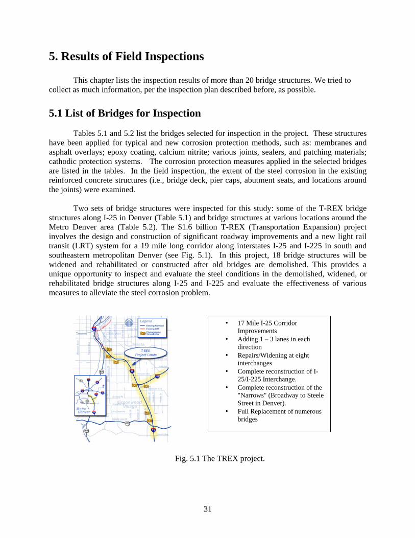
5. Results of Field Inspections
This chapter lists the inspection results of more than 20 bridge structures. We tried to collect as much information, per the inspection plan described before, as possible. 5.1 List of Bridges for Inspection
Tables 5.1 and 5.2 list the bridges selected for inspection in the project. These structures
have been applied for typical and new corrosion protection methods, such as: membranes and asphalt overlays; epoxy coating, calcium nitrite; various joints, sealers, and patching materials; cathodic protection systems. The corrosion protection measures applied in the selected bridges are listed in the tables. In the field inspection, the extent of the steel corrosion in the existing reinforced concrete structures (i.e., bridge deck, pier caps, abutment seats, and locations around the joints) were examined.
Two sets of bridge structures were inspected for this study: some of the T-REX bridge
structures along I-25 in Denver (Table 5.1) and bridge structures at various locations around the Metro Denver area (Table 5.2). The $1.6 billion T-REX (Transportation Expansion) project involves the design and construction of significant roadway improvements and a new light rail transit (LRT) system for a 19 mile long corridor along interstates I-25 and I-225 in south and southeastern metropolitan Denver (see Fig. 5.1). In this project, 18 bridge structures will be widened and rehabilitated or constructed after old bridges are demolished. This provides a unique opportunity to inspect and evaluate the steel conditions in the demolished, widened, or rehabilitated bridge structures along I-25 and I-225 and evaluate the effectiveness of various measures to alleviate the steel corrosion problem.
• 17 Mile I-25 Corridor Improvements
• Adding 1 – 3 lanes in each direction
• Repairs/Widening at eight interchanges
• Complete reconstruction of I-25/I-225 Interchange.
• Complete reconstruction of the "Narrows" (Broadway to Steele Street in Denver).
• Full Replacement of numerous bridges
Fig. 5.1 The TREX project.
31

Table 5.1 List of TREX bridges inspected
No. Name of bridge
Completion date
Structure number
Corrosion protections applied
1 Arapahoe/I25 Widening - Undergoing Epoxy-coated rebar
2 Orchard/I25 Widening - Undergoing Asphalt membrane overlay
3 Dry Creek Rd/I25
Widening (prestressed
concrete bridge)- Appr. 2004
Asphalt membrane overlay and
epoxy-coated rebar
4 NB Belleview/I25
Widening - Undergoing Asphalt membrane overlay
5 Hampden/I25
Has not been decided at the time
of inspection Asphalt membrane overlay
6 Emerson/I25
New construction/ complete demolition
- Asphalt overlay
7 I25 over Univ/I25
New construction/ complete demolition
- Asphalt overlay
32

Table 5.2 List of bridges inspected with various corrosion protection systems
No. Name of bridge Completion date
Structure number
Corrosion protections applied
1 A bridge on SH 85 in Greeley
1960, repaired 2002 C-18-BK Cathodic protection installed in
2001
2 A bridge on SH 34 in Greeley
1960, repaired 2002 C-18-J Cathodic protection installed in
2001
3 Wolfensburger Rd.
WB over I-25.
End of 1995 G-17-DF: bare
decks prestressed I girder
Epoxy-coated rebars and Class D plus low dose Silica fume and
calcium nitrite
4 Wolfensburger Rd.
WB over Plum Creek
End of 1995 G-17-DE: A bare deck Prestressed
Box girder structure Epoxy-coated rebars and Class D
5 Kettle Creek bridge in Colorado Springs 1996 I-17-KZ Epoxy-coated rebars and
Inhibitors
6 A bridge on I-70 EB Mp 293.6
1958, repaired 1997 F-18-AQ Cathodic protection AND
CONCRETE OVERLAY
7 A bridge on I-70 EB Mp 294.7
1958, repaired 1997 F-18-E Cathodic protection AND
CONCRETE OVERLAY
8 I-70 EB over Moss St 1969 F-16-HO
Asphalt membrane overlay
9 Yosemite over I-25 1983 F-17-IJ Asphalt membrane overlay with epoxy-coated rebars
5.2 Inspection Results of T-REX Bridges
A series of meetings with TREX personnel were held to discuss a possible field inspection to detect the severity of corrosion damage to bridges. Since TREX project is a long-term project (eight years), it was not possible to follow their schedule for this study. A few bridges were selected to inspect with a possibility of concrete coring work. In this study, seven bridges (5 in the south segment and 2 in the north segment) were inspected and analyzed. The photos taken during the inspections are included in Appendix B1, and the chloride profiles obtained from concrete cores are included in Appendix B2.
33

5.2.1 I-25 over Arapahoe (based on an interview with TREX personnel) Inspection Date: Performed by TREX Personnel Structure Number: F-17-GJ When this project started, some sections of the bridge were already removed, and repair jobs were already completed. An interview was conducted with CDOT engineers to obtain the information on the condition of rebars. • Epoxy-coated steel placed in mid 80’s • 10% of exposed rebar showed the epoxy flaking with rust spots • Digital photos and information were provided by Mr. Siegfried of CDOT
From Figs. B1.1.1 to B1.1.5, one can see that many rebar were corroded, although the epoxy coating is less than 20 year old. From Fig. B1.1.6, one can also see that the concrete was not in good condition.
5.2.2 I-25 over Orchard (north bound) Inspection Date: June, 2002 Structure Number: F-17-DE
A small portion (about 10 feet) near the outside edges of old I-25 was inspected. This area was most likely widened with black steel in the mid ‘70s. The structure was built in the ‘60s with black steel. A membrane with asphalt overlay was placed on top of the deck (see Fig. B1.2.2).
Delaminations were found on the deck (see Fig. B1.2.3). The exposed steel bars in the
repaired areas were heavily corroded (rusting and loss of steel, see Fig. B1.2.4, Fig. B1.2.6, and Fig. B1.2.7), especially in the areas close to the concrete barrier. This could be attributed to two reasons: 1) surface water drains to and accumulates in the area near the barrier walls (see Fig. B1.2.8), and 2) salt and other deicing chemicals were splashed on the barrier wall by traffic. This ‘puddle’ of chloride solution can take, in some cases, several days to drain or evaporate and will penetrate the deck relatively quickly. Despite the severe corrosion of rebar, some black bars were, surprisingly, in good condition after more than 30 years of service (see Fig. B1.2.5). This shows that good concrete cover and good drainage condition are very important.
The percentage of the repaired area in this section was around 10%. The repair is Class 2
damage repair, where corroded steel was kept and the new cover made of type DT CDOT concrete mix. 5.2.3 I-25 over Dry Creek – South Bound Inspection Date: August 22, 2002 Structure Number: F-17-IV
34

The Dry Creek Rd can be categorized as one of the new bridges in the TREX project. It was built in 1985. The main corrosion protection method used was asphalt membrane overlay (see Figs. B1.3.1, B1.3.2, and B1.3.3). The bridge was widened in 1987.
The inspection was conducted on Aug. 22, 2002, while the traffic was still on the main, center lane. Two concrete cores were taken around the damaged areas of asphalt pavement. From the chloride profile analysis, one can see that the chloride concentrations are very low. The shoulder lane contains more chloride than the driving lane (see Appendix B2.1). 5.2.4 I-25 over Belleview – North Bound Inspection Date: July 31, 2002 Structure Number: F-17-CO
Visual inspection was conducted on NB Belleview on July 31, 2002. The bridge was built in 1960, and was widened in 1975. The major damage was found in the joint areas (between 1960 and 1975 sections). No signs of significant damage were encountered in the 1975’s section.
Delamination and corrosion of rebars were found (see Figs. B1.4.2 – B1.4.5). Most of
the photos were taken of the delaminated and corroded areas. The overhang built in 1960 was planned to be completely removed because of the severity of the damages, such as delamination and discoloration of concrete (see Fig. B1.4.6). Fig. B1.4.7 and Fig. B1.4.8 show the leakage and cracking on the bottom of the deck. 5.2.5 Hampden over I-25 Structure Number: F-17-W
The bridge was built in 1958 and widened in 1980. This bridge has not been planned to have any rehabilitation, widening, or reconstruction done at the time of inspection. The major damages found in the bridge were efflorescence, cracking and spalling, all due to steel corrosion. Some parts of the bridge in the bottom deck and bottom girder were heavily spalled due mainly to steel corrosion (see Figs. B1.5.1 to B1.5.7). One may notice that all the cracking and spalling of the concrete occurred in the bottom of the slab or beams, which imply that there have been continues leakage and salt solution accumulation in the areas. 5.2.6 Emerson over I-25 Inspection Date: June 9, 2003 Structure Number: F-17-CX
The bridge was built in 1958. Since the bridge was almost completely demolished before the site visit (see Fig. B1.6.1 and Fig. B1.6.2), the analysis was focused on the concrete core taken from the bridge, which was used for the analysis of chloride profile. Appendix B2.2 shows
35

the chloride concentration profile, which is very high, higher than the threshold value for corrosion initiation. 5.2.7 I-25 over University Boulevard Inspection Date: July 2, 2003 Structure Number: F-17-CQ
The bridge was built in 1968. Since the bridge deck was almost completely demolished before the site visit, the study was focused on the concrete coring analysis. Appendix B2.3 shows the chloride concentration profile, which is much higher than the threshold value for corrosion initiation.
Some visual inspection was performed on the remaining parts of the bottom deck.
Efflorescence, cracking, and spalling were encountered particularly in the overhang (cantilever) area (see Fig. B1.7.2 to Fig. B1.7.5). Fig. B1.7.7 shows a corroded rebar. 5.3 Inspection Results of Bridges with Various Corrosion Protection Systems
The photos and crack mappings taken during the inspections are included in Appendix C, and the chloride profiles obtained from concrete cores are included in Appendix D. 5.3.1 The Bridge on SH 85 in Greeley Inspection date: Oct 2, 2001 and Nov 11, 2002 Structure ID: C-18-BK Built: 1961 Concrete Mix Design: an old CDOT concrete mix developed in the 1960’s Deicing Salt: High Annual Daily Traffic: 11,120 Condition Rating: 5 (Fair) General description The structure is a three span bridge of steel (I-beam) composite girder with approximately 31° skew-angle (angle between centerline of a pier and a line normal to the roadway centerline) to accommodate the curved (turn) structure. The corrosion protection method used is asphalt overlay with Galvashield (cathodic protection) installed in 2001. Visual/corrosion inspection This bridge was inspected three times recently. The first time was before the installation of Galvashield. The second was after the installation of Galvashield and before the installation of the asphalt overlay. The third was after the placement of the overlay.
36

The third inspection focused on a half lane including the shoulder lane. Because the deck
is fully covered by new asphalt overlay, no crack mapping was performed. The visual inspection concentrated on the bottom deck, pier cap, and piers. As shown in the figures, heavy efflorescence was encountered in the bottom deck and pier caps. Some piers have already shown heavy spalling and cracking due to large amounts of rust formation. Some of the photos taken during the first inspection are shown in Appendix C. One can see that severe corrosion damage took place in the bridge deck (see Fig. C.1.14). Fig. C.1.7a is a photo taken during the second inspection, which shows cracking and spalling in a pier. Fig. C.1.7b is a photo taken in the third inspection for the same pier. One can see that severe spalling occurred in the pier, which indicates that the corrosion damage developed rapidly. Coring analysis
Three cores with 3 inches in diameter and 3.5 to 6 inches in length were taken, one from the shoulder lane and two from the driving lane. The cores consist of asphalt overlay (1.5 inches) and concrete layer (2-4 inches). No membrane overlay was found. During the coring process, the asphalt overlay was easily broken or delaminated from the concrete layer. This may be because the core diameter was quite small. However, it can be seen from another bridge in the Greeley area (on SH34 – see the next section) that the asphalt overlays in the extracted cores are still strongly attached to the concrete deck layers. It can be seen from the steel bars that the concrete cover in the shoulder and driving lanes is 2 ½ inches which is a more than adequate cover compared with the specification (2 ¼ inches). Litter corrosion rust was found on the surface of the bars in the core extracted from the shoulder lane. Significant cracking was found in the core extracted from the shoulder lane.
It can be seen from Appendix D that the chloride concentrations are about 0.022 % near
the steel surface. Note that in this study the concentration analysis of chloride ions was performed at half inch interval from 0.5 up to 2 inches. At the surface (0-0.5 inch depth), the amount of chloride ions is 0.053% (shoulder lane) and 0.123% (driving lane). At the 2 inch depth, the chloride concentration is 0.022% (shoulder lane) and 0.029% (driving lane). Note that this is the total chloride concentration in 1.5 gram of concrete powder extracted from the cores. The chloride concentration in the shoulder lane seems to be smaller than in the driving lane. This is due to the fact that the core at the shoulder lane was taken at a higher elevation (i.e., there is a slope on the bridge deck).
Studying the chloride concentration threshold provided in Table 2.1 (with the broad range
from 0.02% to 0.055% of total chloride concentration), it can be concluded that the corrosion may just have started in some localized areas. It can be seen from the condition of the steel bars extracted from the cores that some corrosion rust was found in the small areas of steel surfaces. Conclusions/observations The Galvashield corrosion protection system with asphalt overlay was installed to prevent further corrosion deterioration, particularly in the bridge deck area. Since the
37

galvashield was just installed in 2001, it will take several years to assess the effectiveness of this corrosion protection system.
Based on the chloride concentration at the rebar level, which is much higher than the
critical concentration, one can estimate that the corrosion process may continue in the area of the deck where Galvashield was not installed. As shown in Fig. C.1.15, the corrosion protection system was not installed in the entire bridge deck.
A certain type of corrosion protection system needs to be implemented on the lower part
of the bridge structures such as piers, pier caps, and steel girders. Otherwise, the corrosion damage that already started in the structure will continue at a very fast rate. Also, since the bridge deck has a skewed and sloped geometry to maintain a good drainage, it is important to prevent the free flow of deicing solution to the lower part of the structural components. 5.3.2 The Bridge on SH34-Business Route in Greeley Inspection date: Oct 2, 2001 and Nov 11, 2002 Structure ID: C-18-J Built: 1961 Deicing Salt: Low Annual Daily Traffic: 1701 Condition Rating: 4 (Poor) General description The structure is located on the SH34 Business Route over South Platte River. The total length of this structure is 819 ft divided into 14 spans of concrete, prestressed girders (CPG). The corrosion protection system used in this bridge is Galvashield cathodic protection, installed in 2001 in addition to asphalt with membrane overlay. Visual/corrosion inspection Because the deck is fully covered by a new asphalt overlay, no crack mapping was performed. The visual inspection focused on the bottom deck and pier caps. As shown in the figures (Appendix C2), spalling and cracks with significant width were discovered in the majority of pier caps. This may indicate that corrosion activity has occurred in the pier cap areas. It can also be seen that the efflorescence has occupied some areas of the bottom deck of the bridge. The membrane, asphalt overlay, and Galvashield corrosion protection system have been installed only on the bridge deck area. Coring analysis
Three cores with 3 inches in diameter and 4” to 7” in length were taken from the South Bound, one from the shoulder lane and two from the driving lane. Since there are no signs of cracking in the deck, the cores were taken randomly at the last two spans of the bridge. The
38

cores consist of 1.5 inches (in the shoulder lane) to 2 inches (in the driving lane) of asphalt overlay and 2 to 5 inches in length of concrete. From the cores extracted, it can be seen that the membrane and asphalt overlay are in good condition. No major delamination was encountered in these cores. Some steel bars were also extracted from the deck. The concrete cover both at the shoulder and driving lanes are about 2 inches, which seems lower than the new specification of concrete cover from CDOT. From the steel bars extracted in the cores, it can be seen that the corrosion activity has already started in one of these rebars (see figures in Appendix C2).
The amount of chloride concentration at the 0-0.5 inches of concrete depth is 0.23%
(shoulder lane) and 0.08% (driving lane). At the 2 inch depth, the total concentration is 0.09% (shoulder lane) and 0.05% (driving lane). All concentrations are higher than the critical concentration. In this case, the chloride concentration at the shoulder lane is larger than that at the driving lane. The chloride concentration profiles are shown in Appendix D2. Conclusions/observations No significant damage was seen in the bridge deck area. This is due mainly to the fact that the overlay has just been installed. It will take some years to investigate the effectiveness of this corrosion protection system.
It is recommended that repair and rehabilitation of bridge piers be implemented as soon as possible considering that the significant corrosion activity is deteriorating the structure at a very fast rate. 5.3.3 Wolfensburger Rd. WB over I-25 Inspection date: Nov 06, 2002 started at 12:00 pm Structure ID: G-17-DF Built: 1995 (end of completion) Concrete mix design: Class D with Fly ash, plus low dose Silica fume and calcium nitrite Deicing Salt: Moderate Annual Daily Traffic: 4650 Condition Rating: 8 (Very Good) General Description
The structure is a two-span-bridge of prestressed concrete box girder with the total length of 204 ft. The completion of construction was in the end of 1995. Epoxy-coated rebars, Class D with Fly ash, low dose Silica fume, and calcium nitrite were used as corrosion protection measures. This structure was an experiment in silica fume and corrosion inhibitor use in new structures. Visual Inspection Longitudinal cracks are the major crack patterns in the deck. The crack width varies from 0.009 – 0.013 in.
39

Corrosion Inspection No serious corrosion damage. such as major cracking or spalling was found in this bridge. However, efflorescence is found almost everywhere on the bottom side of the deck, especially on the new part of bridge (see figures in Appendix C3). The older deck is found to be relatively free from efflorescence. Coring Analysis
It was very difficult for the coring machine to penetrate the concrete deck. As a result, only one 4-inch-diameter core was taken in the cracked region on the driving lane. The rebar was not extracted. It can be measured from the rebar in the coring hole that the concrete cover is about 2 ¼ inches.
The amount of chloride concentration at the surface (up to 0.5 inch depth) is 0.35% and at
the 2 inch depth is 0.09%, which is higher than the suggested critical values (0.020% - 0.055%). The distributions of chloride concentration can be seen in Appendix D3. Conclusions/Observations
Since no ECR was extracted from the core, no conclusive evidence can be made regarding the effectiveness of the corrosion protection systems. 5.3.4 Wolfensburger Rd. WB over Plum Creek Inspection date: Nov 06, 2002 starting at 11:00 am Structure ID: G-17-DE Built: 1995 (end of completion) Concrete mix design: Class D with Fly Ash Deicing Salt: Moderate Annual Daily Traffic: 2907 Condition Rating: 8 (Very Good) General Description
The structure is a two-span prestressed concrete girder (CPG) with a total length and width of 197 ft and 28 ft, respectively. This structure was built in 1995. ECR is used as the main corrosion protection in addition to the concrete mix design Class D Fly Ash. Visual Inspection
The inspection was conducted on the north lane of the bridge. As shown in the crack mapping and photos (see Figures in Appendix C4), longitudinal cracks are the major crack patterns found in the deck. The crack width varies from 0.003-0.005 in.
40

Corrosion Inspection
No major sign of corrosion distress or efflorescence was found in this structure. Coring Analysis Only one core of a 4-inch-diameter was taken in the cracked region on the driving lane. The measured concrete cover is about 3 inches, which is in accordance with CDOT specifications.
The chloride concentration at the deck surface (up to 0.5 inch depth) is 0.19% and at the 2 inch depth is 0.07%, which is larger than the critical value (0.020% - 0.055%). The distributions of chloride concentration can be seen in Appendix D4. Conclusions/Observations Considering the high chloride concentration found near the steel bar and that there is no sign of corrosion damage, the corrosion protection system used in the bridge (i.e., epoxy coating) seems to be working very well. 5.3.5 Kettle Creek Bridge on SH 83 – Colorado Springs Inspection date: Oct 28, 2002 Structure ID: I-17-KZ, SH 83 mp 18.2 over Kettle Creek Built: 1994 – The SB with epoxy-coated rebar was poured on Dec 19, 1995; The NB with
calcium nitrite and black steel was poured on Jan 12, 1996 Concrete Mix Design: Class D Deicing Salt: High Annual Daily Traffic: 19,528 Condition Rating: 7 (Good) General description
The bridge is located approximately two miles north of the Academy Boulevard and SH 83 in Colorado Springs (See Fig. C.5.1). The bridge has a two span prestressed concrete girder with a 182 ft long, 90 ft wide, and 16 ft raised median. The deck is 8.5 inches thick, and it is bare concrete with 2.5 inches nominal cover plus a 0.5 inch sacrificial wearing surface for sawed grooves.
There are two corrosion protection systems applied in this bridge, i.e., conventional ECR
in the South Bound and calcium nitrite corrosion inhibitor in the North Bound. The purpose of having two corrosion protection systems installed side by side in one bridge was to compare which system is more effective. Some corrosion monitoring sensors were installed in the bridge decks by W.R. Grace, which will be described in detail later.
41

Transverse cracks with the width of 0.03 – 0.05 in. are the dominant crack patterns found both in the south and north bound lanes (see photos and crack mappings in Appendix C5). The crack mapping is very useful for investigating the effectiveness of the two corrosion protection systems, especially the one without the ECR. Chloride solutions penetrate easily into the cracked concrete and reach the rebar. This makes the corrosion inhibitor less effective than the epoxy coating. Corrosion inspection Corrosion inspection was focused on the deck area where the corrosion monitoring sensors were installed. The corrosion monitoring devices were installed by Grace Construction Products and sponsored by CDOT. The corrosion probes were placed in the concrete deck of the bridge. The devices can measure the corrosion current or corrosion potential generated on the surface of steel (see Fig. 5.2). In addition, the devices can measure the corrosion rate based on the linear polarization technique. Visual/cracking inspection
Three electrodes are used to make the measurement: the working electrode (steel reinforcement), the counter electrode (316L stainless steel rod, ½” x ½” x 6”) and a reference electrode (316L stainless steel probe, ¼” diameter, insulated except at the tip). The system is shown in Fig. 5.2.
Steel Reinforcement
316L Stainless Steel, 1/2” x 1/2” x 6” length
1/4” dia 316L Stainless Steel, Insulated except at tip
1/2”
1/4”
Fig. 5.2 Configuration of corrosion measuring/monitoring probes
42

n
Epoxy Coated Steel without Sodium Nitrate Inhibitor 26’ 8” 7’ 11” 3 2 58’ 0” 57’ 9” 26’ 8” 17’ 8” 8 1 15’ 6” 15’ 5”
Black Steel Side with Sodium Nitrate Inhibitor 36’ 1” 18’ 9” 5 6 42’ 2” 38’ 7” 37’ 7” 17’ 4”
7 4
16’ 11” 17’ 0”
Fig. 5.3 The locations of the embedded probes in the concrete deck
43

The devices were placed at eight specific locations as shown in Fig. 5.3. During the inspection, measurements were made using the open circuit potential or corrosion potential, Ecorr. This was a voltage measurement between the working and reference electrodes, without any externally applied current or potential. This procedure is similar to the half-cell potential method.
One should keep in mind that the measured potentials are a comprehensive indicator for
the condition of the concrete near the rebar surface, as well as, the condition of the rebar. In Fig. 5.2, the electric conductivity of the concrete filling the ¼” gap between the reinforcement and the perpendicular stainless steel bar plays a very important role in the measurement. The measured potential will be very low if the conductivity of the concrete is low, even if severe corrosion is taking place. Therefore, the absolute values obtained at a specific time do not reflect the real corrosion rate of the steel bar. The variation of the potential with time at a specific location has the most important value for evaluating the effectiveness of the protection systems.
Table 5.3 shows the temporal variations of the potentials from April 1994 to December
1998 and to October 2002. The basic trend for the potential measurements is that when the corrosion potential increases with time (i.e., becomes more positive), the susceptibility to corrosion decreases. From Table 5.3, one can see that all corrosion potentials increased over time, except No. 5., indicating that no corrosion is taking place in the steel at most of the locations.
Now, we can compare the effectiveness of epoxy coating and corrosion inhibitors. No. 1, 2, 3, and 8 (epoxy coating) are all positive, which mean that there is no corrosion occurring on the steel. No. 4, 5, 6, and 7 (corrosion inhibitor) are in positive and in negative. However, the negative values are still higher than -200 mV, which indicates that there is no corrosion occurring on the steel surface at that area.
Strictly speaking, the measurements in December 1998 and the measurements in October
2002 may not be compared directly, because of the different environmental conditions at the times of measurement. A more accurate comparison can be done only if the measurements are made at the same temperature and humidity levels, which is apparently very difficult in the field. Figs. 5.4 and 5.5 show spatial distributions of the potentials along the sides of the bridge decks for the data obtained in 1998 and 2002.
Table 5.3 Corrosion potentials measured in three different years Probe No. Protection Ecorr (mV) Ecorr (mV) Ecorr (mV)
1994 1998 2002 1 Epoxy -62.58 -32.05 6 2 Epoxy -6.85 -133.7 4.6
3 Epoxy -107 -7.291 0
4 DCI -149 -65.11 -1 5 DCI -183 109.4 -2.5 6 DCI -135 -27.55 24.5 7 DCI -95.42 -75.26 73.7 8 Epoxy -119 -85.74 2
44
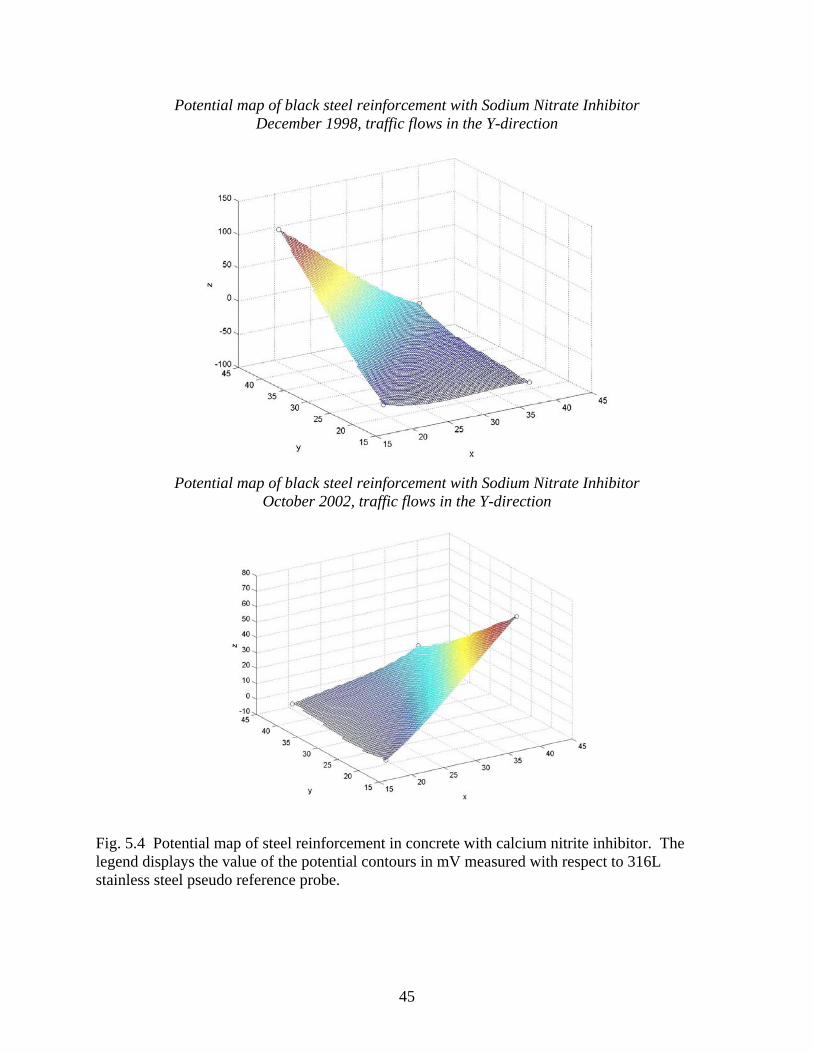
Potential map of black steel reinforcement with Sodium Nitrate Inhibitor December 1998, traffic flows in the Y-direction
Potential map of black steel reinforcement with Sodium Nitrate Inhibitor
October 2002, traffic flows in the Y-direction
Fig. 5.4 Potential map of steel reinforcement in concrete with calcium nitrite inhibitor. The legend displays the value of the potential contours in mV measured with respect to 316L stainless steel pseudo reference probe.
45

Potential map of epoxy-coated reinforcement December 1998, traffic flows in the Y-direction
Potential map of epoxy-coated reinforcement October 2002, traffic flows in the Y-direction
Fig. 5.5 Potential map of epoxy-coated reinforcement in concrete. The legend displays the value of the potential contours in mV measured with respect to 316L stainless steel pseudo
reference probe.
46

Coring analysis
The concrete cover can be measured from the cores, which are about 3 inches. This is more than CDOT specification (2 ¼ inches). In the south bound lane, the amount of chloride concentration at 2 in. depth is 0.015% (shoulder lane) and 0.079% (driving lane). While in the north bound lane, the concentration is 0.021% (shoulder lane) and 0.065% (driving lane). The values at the driving lane are higher than the range of the suggested critical values (0.020% - 0.055%). The chloride concentration distributions versus concrete depth can be seen in Appendix D5. Conclusions/Observations The results of corrosion potential measurements show that the potentials at all locations are higher than –200 mV. Therefore, there is no corrosion activity taking place in the locations. Comparing our measurements with the records of 1998 (Grace Construction Products, 1998), one can see that the bridge decks have been protected effectively by the corrosion protection systems. It is important to point out that these results only show the states of the applied corrosion protection systems at the eight selected locations, and they do not represent the situation of the entire bridge decks.
Because calcium nitrite as a corrosion inhibitor reacts chemically with the reinforcing steel, the effectiveness of calcium nitrite depends on the ratio of chloride ions-to-nitrite ions, which should be kept below 1.0 over the entire life of the structure (Virmani and Clemena, 1998). The deck structure is problematic when significant cracks are present. Therefore, the application of corrosion inhibitor must be accompanied by a good quality of concrete (crack free). From the overall observation of the crack mapping on the bridge decks, one may speculate that ECR is a better protection system in the situation where cracks are present. Nevertheless, it will take several more years to compare the severity of corrosion damage in the epoxy-coated rebar to the areas protected by the corrosion inhibitor.
Thus far, no research has been found regarding the comparison on the effectiveness of ECR versus corrosion inhibitor. There was one study on this topic (Virmani and Clemena, 1998) which focused on the effectiveness of various types of corrosion inhibitors in indoor environments. 5.3.6 Bridge on I-70EB on MP 293.6 Inspection date: Nov 18, 2002 Structure ID: F-18-AQ Built: 1960 Concrete Mix Design: Deicing Salt: Moderate Annual Daily Traffic: 7149 Condition Rating: 7 (Good)
47

General Description The bridge has a structural system of three-span continuous reinforced concrete slab girders. The total length is 94 ft. and the total width is 38 ft. The CDOT fieldlog data states that the bridge was built in 1960, widened in 1987, and repaired in 1997.
A cathodic protection system was installed in this bridge to prevent further damage caused by corrosion. There is a control box with a power supply for maintaining an electric current in the protection system (see Fig. C.6.5). This box has been used for controlling both east and west bounds. The inspection was focused on the east bound lane. Cracking inspection No significant cracking or damage was discovered on the bottom deck. However, the crack density on the top deck is very intense. The dominant crack pattern is transversal with the crack width varying from 0.016-0.030 in (see Fig. C.6.7). Corrosion Inspection There were no signs of heavy efflorescence found on the bottom deck. Concrete spalling on the sub-beam part was found (see Fig. C.6.9).
A log form was found in the control box (see Fig. C.6.6). It is shown on the form that the latest inspection for the cathodic protection system was performed on 12/04/2001 by applying current of 6.3 Ampere with 3.0 Volt. Coring Analysis
Three cores, 4 in. diameter and 5 to 6 in. depth were taken as samples from the deck. Two were from the driving lane and one from the shoulder lane. One of the cores on the driving lane was taken in the cracked area. Steel rebar was not obtained from the core extraction. A sections of titanium wire mesh for the cathodic protection system was obtained in one of the cores.
During coring on the deck, the concrete overlay was debonded very easily. In the
overlay, there were cathodic protection anodic meshes which were in good condition. These meshes are anodic in the protection system and supposed to corrode. But with the debonding interface between the old concrete and concrete overlay, the corrosion current may not get through. If this is the case, the protection system will not operate on its full capacity.
The chloride concentration at the 2 inch depth is 0.040% (shoulder lane) and 0.070%
(driving lane). These values are higher than the suggested critical values (0.020% - 0.055%). The distributions of chloride concentration are presented in Appendix D6.
48

Conclusions/Observations Based on the cores extracted, it can be determined that the cathodic protection system in this bridge may not function effectively. It must be noted that in order to have a successful cathodic protection system, the cathodic protection system must have similar resistivity to the concrete in the structure, the current must be uniformly distributed throughout the structure, and the system must be regularly monitored and inspected to ensure that the polarization is in the desired range. It is also important to consider that applying excessive current must be avoided to prevent weakening of the bonding between reinforcement and concrete and also to avoid hydrogen embrittlement.
It is suggested that voltage, current, and half-cell potential measurements in each zone of the cathodically protected bridge be taken every two months (such as the practice by the Missouri Department of Transportation, see Wenzlick 1999). 5.3.7 Bridge on I-70 on MP 294.7 Inspection date: June 06, 2002 Structure ID: F-18-E Built: 1958 Concrete mix design: Deicing Salt: Moderate Annual Daily Traffic: 7149 Condition Rating: 7 (Good) General description
The bridge has three spans with concrete and slab girder systems. The total length of the bridge is 94 ft with 31 ft at each span. The structure was built in 1958, widened in 1985, and repaired in 1997. There is a cathodic protection system installed in the bridge deck to prevent further corrosion damage. Visual/Corrosion inspection The degree of deck cracking is very intense. This may be due to rebar corrosion. Coring analysis
Concrete cores were taken at 4 different locations in the deck. Two cores were taken from the driving lane with many cracks, and the other two cores were taken from the shoulder lanes. The cores are 4 in. diameter with the depth varying between 5 to 6 in.
During the coring process, the cores extracted from the cracking area were easily broken from the interfaces, which means that the top concrete layer used for placing cathodic protection mesh was delaminated from the bottom layer. This is a similar situation with the bridge on MP 293.6 (see Section 5.3.6). From the extracted cores, it can be determined that the delamination
49

occurred at about 1 inch below the concrete deck surface. Chain dragging did not show significant delamination.
The chloride concentration at the 2 inch depth is 0.028% at the shoulder lane and 0.037%
at the driving lane, which are higher than the suggested critical values (0.020% - 0.055%). The distributions of chloride concentration are presented in Appendix D7. Conclusions/observations
Based on the crack patterns observed in the bridge deck (Figs. C.7.6 and C.7.7), the cause of cracking is most likely due to an alkali-silica reaction. Under a cathodic protection system, hydroxyl ions generated at cathodic site can cause alkali-silika reaction resulting in the concrete cracking (Ali, 1993). This may happen especially when the applied current is excessive, causing hydrogen embrittlement.
Considering that this bridge has undergone rehabilitation more than one time, more
frequent maintenance of the cathodic protection needs to be carefully implemented. 5.3.8 I-70 EB over Moss St Inspection date: August 19, 2002 Structure ID: F-16-HO Built: 1969 Concrete Mix Design: Deicing Salt: Annual Daily Traffic: Condition Rating: General description
The bridge is located on I-70 East Bound at MP 261.305. The bridge was built in 1969 and was repaired in 1978. The total length of the structure is 104 ft with 51.5 ft road width. The girder system is CSGC (Concrete Slab and Girder Continuous – Poured in Place). The corrosion protection applied on the deck is asphalt membrane overlay. Visual inspection
Crack mappings were performed on the top (asphalt pavement) and bottom of the decks. The chain dragging test was also conducted along the asphalt surface. From experience, it is not appropriate to use the chain dragging test on a deck covered with asphalt membrane overlay. However, due to some significant cracks seen on the surface of the deck, the chain drag was performed to investigate the severity of debonded/delamination asphalt from the membrane or concrete beneath it. The result showed that there are some heavily delaminated areas on the deck. This may indicate that the asphalt and membrane overlay have been damaged.
50

Corrosion inspection
The major corrosion distress is efflorescence with the typical efflorescence (crack) pattern shown in the photos (see Fig. C.8.5). Heavy efflorescence was found in the shoulder and cantilever/overhang areas of the bridge. Coring analysis
Three cores of 4 in. diameter were taken as samples. Two were from the cracked areas and one from the undamaged area. The cores consisted of 3 inches of asphalt and 3 to 4 inches of concrete. It can be seen in the figures (Appendix C8) from the core in the cracked area that the asphalt membrane overlay has heavily delaminated from the concrete layer. The steel rebar was only encountered in the core extracted from the shoulder lane. The sample shows that the steel bar is severely corroded (Fig. C.8.13). The measured concrete cover is about 3 inches which is more than CDOT specifications (2 ¼ inches).
The chloride concentration at the 2 inch depth is 0.017% at the shoulder lane and 0.031%
at the driving lane (see Appendix D8 for the distributions). One can imagine that the steel bars in driving lane would also be corroded severely because of the high chloride concentration.
Appendix D8 shows that the chloride concentration in the driving lane at the depth of 2
in. is higher than the concentration at the surface of the concrete. This may happen when an overlay is placed on top of a concrete deck. The reason is that the new overlay has a very low chloride concentration compared with the old concrete deck, therefore, the chloride ions diffuse from the deck (high concentration) up to the overlay (low concentration) resulting in a lower concentration at the surface of the deck.
Conclusions/observations Many states in the U.S. use membrane only for secondary route bridges (Manning 1995). This is mainly because the service life of membrane depends on the condition of the asphalt overlay and asphalt overlay does not last very long under heavy traffic loads. This bridge is on I-70 with heavy traffic load. One can clearly see that the asphalt overlay has suffered from significant cracking after 25 years of service.
It can be determined from literature that the service life of the asphalt membrane overlay of a new deck is about 15-20 years, and it is about 10 years for a rehabilitated deck (Manning 1995). In many cases, the service life of a membrane is determined by the asphalt overlay. In order to have a high quality asphalt membrane overlay, quality of workmanship is extremely important. It requires a high-density overlay with quality aggregate, proper seams, compaction, bonding techniques, and adequate drainage to ensure a durable asphalt membrane overlay on a bridge deck.
Other corrosion protection measures such as cathodic protection systems need to be
implemented on this bridge to prevent further corrosion damage. Alternatively, a new asphalt
51

membrane overlay can be used to replace the old system. In any case, the bridge on I-70 over Moss St. needs to be rehabilitated or completely replaced.
5.3.9 Yosemite over I-25 Inspection date: Dec 18, 2002 Structure ID: F-17-IJ Built: 1983 Concrete mix design: Deicing Salt: Annual Daily Traffic: Condition Rating: General description The structure has four spans with a total length of 302 ft. and road width of 63 ft. The girder was constructed using CBGCP. The main corrosion protection measures are a membrane asphalt overlay and ECR. Visual/corrosion inspection No sign of serious cracking or corrosion damage were found in this structure. However, since the bridge has a skew/curve with some slope, the flow of deicing solution can cause significant damage to the structure in the future, particularly in the overhang areas. Regular inspection to control this condition needs to be implemented. Note that the flow of deicing solution can reach other parts of the structure such as pier caps and piers. This can lead to potential corrosion damage like that encountered on the SH 85 structure in Greeley (see section 5.3.1). Coring analysis No significant chloride concentration was found in the cores taken from both shoulder and driving lanes (see Appendix D9). The ECRs extracted from the cores are in excellent conditions. The chloride concentration is very low (around 0.002% both at the shoulder and driving lanes). Conclusion/Observation The bridge is in excellent condition.
52

6. Conclusions and Recommendations 6.1 Literature Review Corrosion of reinforced concrete structures have been a significant problem for many state and transportation agencies since the application of deicing salts was introduced. Many researches have been conducted to develop corrosion protection systems that can prolong the life span of reinforced concrete structures. There are many corrosion protection systems discussed in this study, including thickness and quality of concrete cover; membranes and sealers; alternative reinforcements such as ECR; steel bars with metallic coating and cladding (galvanized rebars, stainless steel, copper-clad); alternative solid bars (CFRP, GFRP, etc); electrochemical methods (cathodic protection, electrochemical realkalization, electrochemical chloride extraction); and corrosion inhibiting admixtures. Basic principles, strengths and weaknesses of the corrosion protection methods are reviewed.
The application of some of the systems in Colorado are discussed and summarized. The CDOT and FHWA specifications and technical documentations related to corrosion protection are reviewed.
It is recommended that future study on the effectiveness of corrosion protection system include economic impact (or life cycle cost analysis), which is a combination of the initial cost of the system, any maintenance cost, and/or repair costs that occur within the service life of the structure. 6.2 Inspection Results of TREX Bridges The TREX bridges inspected in this project used three corrosion protection methods: ECR, asphalt overlay, and membranes. Corrosion of steel and corrosion-induced damage in concrete occurred in all bridges except Dry Creek Bridge, which is relatively new. The degree of corrosion is quite high. 6.3 Inspection Results on Various Corrosion Protection Systems Nine bridges with different corrosion protection systems were inspected to study the effectiveness of these protection methods which include:
• Asphalt overlay with membrane (I-70 over Moss St and Yosemite over I-25). • ECR and corrosion inhibitor (Kettle Creek Bridge and Wolfensburger bridges in
Colorado Springs). • Impressed-current cathodic protection method (two bridges on I-70 EB at mile posts 293
and 294). • Sacrificial anode cathodic protection method (i.e., Galvashield) with asphalt overlays
(two bridges on SH85 and SH 34 in Greeley).
53

The inspection covered field work such as visual inspection for corrosion induced damages, crack mapping, chain dragging, taking photos for efflorescence and spalling, and laboratory work to determine chloride profiling (chloride ion concentration as a function of concrete depth). The inspected structural components included top deck and bottom deck, pier caps, piers, and girder systems. The following are the conclusions and recommendations based on the literature review and the inspections performed on the selected bridges in Colorado.
• The inspection results of the bridge on SH85 show that bridge geometry plays an important role in corrosion resistance of structural components. Curved and skewed bridges can lead to the flow of deicing salt solution from decks onto other structural components such as pier caps and piers if the drainage system is not in good condition. Therefore, proper drainage should be provided so that the water can drain quickly from the deck. Seepage drains should be provided at low points to prevent water from sitting on top of the membrane.
• From the inspection results of the bridges along I-70 EB, it can be determined that the
application of the cathodic protection method is quite effective in prolonging the life of the bridge decks that would otherwise need to be replaced. However, literature review shows that the electrochemical treatment can lead to negative side effects. The side effects include hydrogen embrittlement, alkali-silica reaction, and bond strength loss. The main factors are the current densities and polarization involved in the treatment. The performance of the cathodic protection system should be monitored continuously in the future.
• Three cathodic protection systems were used in Colorado: sprayed zinc, impressed
current, and sacrificial anode. The available results are not sufficient to conclude which system is more effective. The apparent advantage of sprayed zinc and sacrificial anode systems is that they do not require voltage supply and malignance.
• Although some references have stated the superior performance of corrosion inhibiting
admixtures, the results of the inspection of Kettle Creek Bridge in Colorado Spring showed some areas of weakness which cause some concerns. The rebar protected by the concrete cover with corrosion inhibiting admixtures is more vulnerable to corrosion than that of ECR when significant cracks are present in the deck. The effectiveness of corrosion inhibiting admixture such as calcium nitrite depends on the low ratio of chloride-to-nitrite ion, which can not be maintained when the concentration of chloride ion continuously increases due to the presence of cracks. Therefore, the application of corrosion inhibiting admixtures must be accompanied by a good quality of concrete deck (i.e., no significant cracking on the concrete) or by other protection methods. On the other hand, there are no signs of steel corrosion or deterioration at both types of bridge decks after nine years of service. Continuous monitoring is absolutely needed.
54

• Another suggestion is to enhance the quality control on epoxy coatings, and reduce the possible defects in the coating. If it is economically viable and is needed, use epoxy coating as well as corrosion inhibitors as a double-corrosion protection measure.
• The inspection results of I-70 over Moss St and Yosemite over I-25 demonstrate that the
effectiveness of a membrane heavily depends on service time, traffic load, and weather conditions. After 25 years, the membrane on Moss St. bridge has severe delamination and cracking. The rebars show significant corrosion damage. While the Yosemite bridge is relatively newer, it is in excellent condition. Kansas (K-TRANS, 2000) reported on the performance of waterproof membranes used on bridge decks. In the period between 1967 and 1974, nearly 10,000 m2 of membranes were installed on salt-contaminated bridge decks. These membranes have performed well, with little maintenance. Asphalt riding surfaces have ranged from satisfactory, with some cracking, to excellent. It is recommended that the effectiveness of waterproofing membranes be studied based on bridge deck conditions collected in PONTIS in a future research study.
6.4 Conclusion Remarks In Section 1.2, we listed two objectives of the present project: 1. To determine the extent of the steel corrosion problem in Colorado’s existing reinforced
concrete structures. 2. Provide recommendations to enhance CDOT’s current guidelines for corrosion projection of
reinforcing steel in Colorado bridge structures.
Based on the inspection results in Chapter 5 (TREX bridges and other bridges), we can now answer the first question: corrosion of steel bars in concrete is an existing problem for highway bridges in Colorado. The extent of the problem is quite significant.
Among the three most commonly used protection systems (ECR, corrosion inhibitors, and membranes), the results obtained in the present study are inconclusive for determining which system is better. In general, some of the corrosion protection systems have performed better than the others, but there is no perfect protection system for every type of application. Therefore, in addition to the specific recommendations listed in Section 6.3 and throughout the report, a general recommendation is to use multiple corrosion protection methods, if they are economically viable for the project. Does a multiple corrosion protection system guarantee a better long-term performance of the structure? This is exactly the research topic for an ongoing FHWA Request for Proposal (DTFH61-03-R-00116: Multiple Corrosion Protection Systems for Reinforced Concrete Bridge Components). It will be a five-year project with the funding of $500,000. We should be able to obtain a definite answer after the project is completed.
A follow-up study is very important and necessary. The follow-up study should develop a plan to monitor and evaluate the performance and service life of all corrosion protection systems employed by CDOT. More information affecting the performance of the corrosion protection systems should be collected. Coring and the half-cell potential measurements should
55

be considered as new inspection methods for the extent of corrosion in bridge decks. The study should finalize the preliminary inspection plan developed in this study, and develop a revision to Section 202 of CDOT Standard Specifications to allow testing of all demolished, repaired, and widened bridge decks.
56

7. References Ababneh, A., Farid Benboudjema, and Xi, Y. (2003) “Chloride Penetration in Non-Saturated Concrete”, J. of Materials in Civil Engineering, ASCE, 183-191. Ababneh, A., and Xi, Y. (2002) “An Experimental Study on the Effect of Chloride Penetration on Moisture Diffusion in concrete”, Materials and Structures, RILEM, 35(254), 659-664. ACI Committee 201 (1994) “Guide to Durable Concrete, Chapter 4 – Corrosion of Steel and Other Materials Embedded in Concrete”, Manual of Concrete Practice, Part I. Alonso, C., Andrade, C., Castellote, M., and Castro, P. (2000) “Chloride Threshold Values to Depassivate Reinforcing Bars Embedded in a Standardized OPC Mortar”, Cement and Concrete Research, 30, 1047-1055. Al-Qadi, I.L., Weyers, R.E., Galagedera, N.L., Cady, P.D. (1992) “Condition Evaluation of Concrete Bridge Relative to Reinforcement Corrosion, Vol. 4: Deck Membrane Effectiveness and a Method for Evaluating Membrane Integrity”, Strategic Highway Research Program Report, SHRP-S-326. Attanayaka, U., Ng, S., and Aktan, H., (2002) “Criteria and Benefits of Penetrating Sealants for Concrete Bridge Decks”, MDOT Research Report RC-1424, CSD 2002-03, 98p. Auyeung, Y., Balaguru, P., and Chung, L. (2002) “Bond Behavior of Corroded Reinforcement Bars”, ACI Materials Journal, 97(2), Mar.-April, 214-220. Bennett, J.E., Bartholomew, J.J., Bushman, J.B., Clear, K.C., Kamp, R.N., Swiat, W.J. (1993) “Cathodic Protection of Concrete Bridges: A Manual of Practice”, Strategic Highway Research Program Report, SHRP-S-372. Berke, N.S. (1986) "Corrosion Rates of Steel in Concrete", ASTM Standardization News, 14,3, 57-61. Berke, N. (1991). “Corrosion inhibitors in concrete.” Concrete International, 13.7, 24-27. Berke, N.S, Dallaire, M.P., Weyers, R.E., Henry, M., Peterson, J.E., and Prowell, B. (1992). “Impregnation of Concrete with Corrosion Inhibitors.” Corrosion Forms and Control for Infrastructure, ASTM STP 1137, Victor Chaker Ed., 300-327. Berke, N. et al. (2003) “Accelerated Mortar Test Method to Determine Chloride Threshold values for Corrosion Initiation”, presented in the ASTM Symposium On Electrochemical Techniques for Evaluating Corrosion Performance and Estimating Service-Life of Reinforced Concrete, June 18, Denver, Colorado. Brown, M., Weyers, R.E., and Sprinkel, M.M. (2003) “Service Life Extension of Virginia Bridge Decks Afforded by Epoxy-Coated Reinforcement”, presented in the ASTM Symposium On
57

Electrochemical Techniques for Evaluating Corrosion Performance and Estimating Service-Life of Reinforced Concrete, June 18, Denver, Colorado. Browne, R. (1982) "Design Prediction of the Life for Reinforced Concrete in a Marine and Other Chloride Environment", Durability of Building Materials, 1, 2, 113-125. Cady, P.D., and Weyers, R.E. (1992) "Predicting Service Life of Concrete Bridge Decks Subject to Reinforcement Corrosion", in Corrosion Forms & Control for Infrastructure, San Diego, CA, Nov. Carter, P. (1991) “Sealing to Improve Durability of Bridge Infrastructure Concrete”, Concrete International, 13.7, 33-36. Concrete Society (1998) “Guidance on the Use of Stainless Steel Reinforcement”, Concrete Society Technical Report 51. Coronelli, D. (2002) “Corrosion Cracking and Bond Strength Modeling for Corroded Bars in Reinforced Concrete”, ACI Materials Journal, 99(3), May-June, 267-276. Darling, D. and Rakshpal, R. (1998) “Green Chemistry Applied to Corrosion and Scale Inhibitors.” Materials Performance, 37.12, 42-45. ElTech Research Corp. (1993a) “Cathotic Protection of Reinforced Concrete Bridge Elements: A State-of-the-Art Report”, Strategic Highway Research Program Report, SHRP-S-337. ElTech Research Corp. (1993b) “Chloride Removal Implementation Guide”, Strategic Highway Research Program Report, SHRP-S-347. Fadayomi, J. (1997). “Corrosion Inhibitors.” Concrete, 31, 21-22. Gadis, J. and Rosenberg, A. (1987) “The Inhibition of Chloride-Induced Corrosion in Reinforced Concrete by Calcium Nitrite”, Cement, Concrete, and Aggregates, 9, 30-33. Gannon, E.J., and Cady, P.D. (1993) “Condition Evaluation of Concrete Bridge Relative to Reinforcement Corrosion, Vol. 1: State-of-the-Art of Existing Method”, Strategic Highway Research Program Report, SHRP-S-323. Grace Construction Product (1998), Corrosion Measurement of Steel Reinforcement in the Kettle Creek Bridge (Rt. 83) Colorado Springs, Colorado, A Memo, December 2-3, 1998. Hansen, W., Jensen, E.A., and Mohr, P. (2001) “The Effect of Higher Strength and Associated Concrete Properties on Pavement Performance”, FHWA Technical Report, FHWA-RD-00-161, The U.S. Department of Transportation, Federal Highway Administration. Herald, S.E., Henry, M., Al-Qadi, I.L., Weyers, R.E., Feeney, M.A., Howlum, S.F., Cady, P.D. (1992) “Condition Evaluation of Concrete Bridge Relative to Reinforcement Corrosion, Vol. 6:
58

Method for Field Determination of Total Chloride Content”, Strategic Highway Research Program Report, SHRP-S-328. Holland, T.C. (1992) “Corrosion Protection for Reinforced Concrete: A Summary of Corrosion Prevention Strategies”, Concrete Construction, 37.3. Hooton, R.D., Thomas, M.D.A., and Stanish, K. (2000) “Prediction of Chloride Penetration in Concrete”, FHWA Technical Report, FHWA-RD-00-142, The U.S. Department of Transportation, Federal Highway Administration. Hooton, R.D. (2003) “Studies on Development of Near-Surface, Fluid Penetration Resistance of Concrete for Use in Selecting Appropriate Curing Regimes”, presented in Advances in Cement and Concrete IX: Volume Changes, Cracking, and Durability, Conference chairmen: Lange, D.A., Scrivener, K.L., and Marchand, J., August 10, Copper Mountain, Colorado. Jennifer, L.K., Darwin, D., and Locke C. E, Jr (2000), Evaluation of Corrosion Protection Methods for Reinforced Concrete Highway Structures, Final Report, The Kansas Department of Transportation, K-TRAN: KU-99-6. . Kessler, R.J., Powers, R.G., and Lasa, I.R. (1998). “ Intermittent Cathodic Protection Using Solar Power”, Material Performance, Vol. 37, No. 12, Dec., pp. 14-19. Klongpanichpak, C. (2002) “Evaluation and Repair of Reinforced Concrete Bridges”, Master Report, University of Colorado at Boulder, 103p. Lane, D.S., and Ozyildirim, C. (1999) “Combinations of Pozzolans and Ground, Granulated Blast Furnace Slag for Durable Hydraulic Cement Concrete”, Virginia Transportation Research Council Technical Report, VTRC 00-R1. Li, L.Y., and Page C.L. (2000) “Finite Element Modeling of Chloride Removal from Concrete by an Electrochemical Method”, Corrosion Science, 42, 2145-2165. Locke, C.E. and Siman, A. (1980). “Electrochemistry of Reinforcing Steel in Salt-Contaminated Concrete,” Corrosion in Reinforcing Steel in Concrete, STP 713, American Society of Testing and Materials, Philadelphia, pp. 3-36. Manning, D.G. (1996). “Corrosion Performance of Epoxy-Coating Reinforcing Steel: North America Experience”, Construction and Building Materials, Vol. 10, No.5, Jul., pp. 349-365. McDonald, D.B., Pfeifer, D.W., Krauss, P., and Sherman, M.R. (1994) "Test Methods for New Breeds of Reinforcing Bars", Corrosion and Corrosion Protection of Steel in Concrete, Proc. of Int. Conf., University of Sheffield, July, Vol. II, Ed. by R.N. Swamy, pp. 1155-1171. McDonald, D.B., Sherman, M.R., Pfeifer, D.W. (1995) "The Performance of Bendable and Nonbendable Organic Coatings for Reinforcing Bars in Solution and Cathodic Debonding Tests", Report No. FHWA/RD-94/103, Interim Report for Feb. 1993 - May 1994, 148 pp.
59
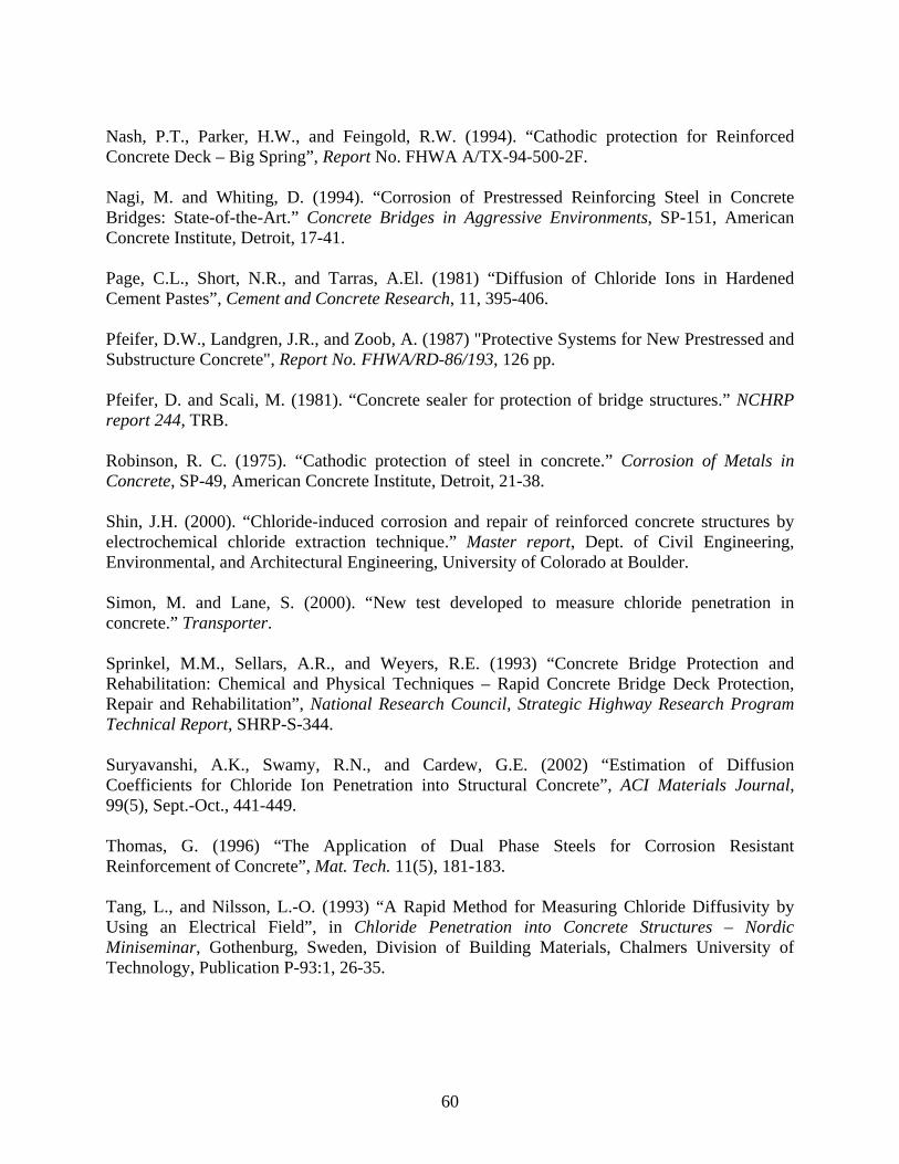
Nash, P.T., Parker, H.W., and Feingold, R.W. (1994). “Cathodic protection for Reinforced Concrete Deck – Big Spring”, Report No. FHWA A/TX-94-500-2F. Nagi, M. and Whiting, D. (1994). “Corrosion of Prestressed Reinforcing Steel in Concrete Bridges: State-of-the-Art.” Concrete Bridges in Aggressive Environments, SP-151, American Concrete Institute, Detroit, 17-41. Page, C.L., Short, N.R., and Tarras, A.El. (1981) “Diffusion of Chloride Ions in Hardened Cement Pastes”, Cement and Concrete Research, 11, 395-406. Pfeifer, D.W., Landgren, J.R., and Zoob, A. (1987) "Protective Systems for New Prestressed and Substructure Concrete", Report No. FHWA/RD-86/193, 126 pp. Pfeifer, D. and Scali, M. (1981). “Concrete sealer for protection of bridge structures.” NCHRP report 244, TRB. Robinson, R. C. (1975). “Cathodic protection of steel in concrete.” Corrosion of Metals in Concrete, SP-49, American Concrete Institute, Detroit, 21-38. Shin, J.H. (2000). “Chloride-induced corrosion and repair of reinforced concrete structures by electrochemical chloride extraction technique.” Master report, Dept. of Civil Engineering, Environmental, and Architectural Engineering, University of Colorado at Boulder. Simon, M. and Lane, S. (2000). “New test developed to measure chloride penetration in concrete.” Transporter. Sprinkel, M.M., Sellars, A.R., and Weyers, R.E. (1993) “Concrete Bridge Protection and Rehabilitation: Chemical and Physical Techniques – Rapid Concrete Bridge Deck Protection, Repair and Rehabilitation”, National Research Council, Strategic Highway Research Program Technical Report, SHRP-S-344. Suryavanshi, A.K., Swamy, R.N., and Cardew, G.E. (2002) “Estimation of Diffusion Coefficients for Chloride Ion Penetration into Structural Concrete”, ACI Materials Journal, 99(5), Sept.-Oct., 441-449. Thomas, G. (1996) “The Application of Dual Phase Steels for Corrosion Resistant Reinforcement of Concrete”, Mat. Tech. 11(5), 181-183. Tang, L., and Nilsson, L.-O. (1993) “A Rapid Method for Measuring Chloride Diffusivity by Using an Electrical Field”, in Chloride Penetration into Concrete Structures – Nordic Miniseminar, Gothenburg, Sweden, Division of Building Materials, Chalmers University of Technology, Publication P-93:1, 26-35.
60

Thompson, N.G., and Lankard, D.R. (1999) “Optimization of Concrete and Repair Materials for Corrosion Resistance”, FHWA Technical Report, FHWA-RD-99-096, The U.S. Department of Transportation, Federal Highway Administration. Virmani, Y.P., Clear, K.C., and Pasko Jr., T.J. (1983). “Time to Corrosion of Reinforcing Steel in Concrete Slabs Vol. 5 – Calcium Nitrite Admixture or Epoxy-Coated Reinforcing Bars as Corrosion Protection Systems,” Report No. FHWA-RD-83-012, Federal Highway Administration, Washington, D.C. Virmani, Y.P., and Clemena, G.G. (1998). “Corrosion protection – Concrete bridges.” FHWA Technical Report, FHWA-RD-98-088. Vorster, M.C., Merrigan, J.P., Lewis, R.W., and Weyers, R.E. (1992) “Techniques for Concrete Removal and Bar Cleaning on Bridge Rehabilitation Projects”, National Research Council, Strategic Highway Research Program Technical Report, SHRP-S-336. VTI (2002) www.vatechnologies.com. Wang, Y., Li., L.Y., and Page C.L. (2001) “A Two-Dimensional Model of Electrochemial Chloride Removal from Concrete”, Computational Materials Science, 20, 196-212. Wheat, H.G., and Deshpande, P.G. (2001) “Alternative Reinforcement Materials for Concrete – A State of the Art Review”, Proc. of Corrosion 2001. Weyer, R.E., et. al (1993), Concrete Bridge Protection, Repair, and Rehabilitation relative to reinforcement Corrosion, Report No. SHRP-S-360, Strategic Highway Research Program, National Research Council. Whiting, D., Tabatabai, H., Stejskal, B., Nagi, M. (1999) “Rehabilitation of Prestressed Concrete Bridge Components by Non-Electrical (Conventional) Methods”, FHWA Technical Report, FHWA-RD-98-189, The U.S. Department of Transportation, Federal Highway Administration. Whiting, D., and Stejskal, B.G. (1994). “Corrosion of Prestressed Reinforcing Steel in Concrete Bridges: State-of-the-Art.” Concrete Bridges in Aggressive Environments, SP-151, American Concrete Institute, Detroit, 73-93. Whiting, D., Ost, B., Nagi, M., and Cady, P.D. (1993) “Condition Evaluation of Concrete Bridge Relative to Reinforcement Corrosion, Vol. 5: Methods for Evaluating the Effectiveness of Penetrating Sealers”, Strategic Highway Research Program Report, SHRP-S-327. Whiting, D., and Cady, P.D. (1992) “Condition Evaluation of Concrete Bridge Relative to Reinforcement Corrosion, Vol. 7: Method for Field Measurement of Concrete Permeability”, Strategic Highway Research Program Report, SHRP-S-329. Xi, Y., and Bazant, Z.P. (1999) “Modeling Chloride Penetration in Saturated Concrete”, Journal of Materials in Civil Engineering, ASCE, 11(1), 58-65.
61

Xi, Y., and Ababneh, A. (2000) “Prediction of the Onset of Steel Corrosion in Concrete by Multiscale Chloride Diffusion”, High Performance Concrete – Workability, Strength and Durability, Proc. of the Int. Sym., Editors, Leugn, C., Li, Z., and Ding, J.T., Dec., Hong Kong, 181-186. Xi, Y., Willam, K., and Frangopol, D. (2000) “Multiscale Modeling of Interactive Diffusion Processes of Concrete”, Journal of Engineering Mechanics, ASCE, 126(3), 258-265. Xi, Y., Shing, B., and Xie, Z. (2001) “Development of Optimal Concrete Mix Designs for Bridge Decks”, CDOT Report No. CDOT-DTD-R-2001-11, also see Final report CU/SR-XI-2001/003 to CDOT, 60p. Xi, Y., Asiz, A., Xie, Z.H., Ababneh, A., and Suwito, A. (2002) “Bridge Deck Cracking Study of Colorado Avenue Viaduct and Monument Creek Bridge in Colorado Springs”, Final report CU/SR-XI-2002/002 to the City of Colorado Springs, 76p. Xi, Y., Shing, B., Abu-Hejleh, N., Asiz, A., Suwito, A., Xie, Z.H., Ababneh, A. (2003) “Assessment of the Cracking Problem in Newly Constructed Bridge Decks in Colorado”, Report No. CDOT-DTD-R-2003-3. Zollinger, D.G., Tayabji, S., Smith, K., Yu, H.T., and Liu, J. (2001) “Repair and Rehabilitation of Concrete pavement: Preliminary Guidelines, Vol. II”, FHWA Technical Report, FHWA-01-C-00080, The U.S. Department of Transportation, Federal Highway Administration. Zemajatis, Jerzy, Weyers, Richard E., and Sprinkler, Michael (1999). Contract Report: Performance of Corrosion Inhibitors and Galvanized Steel in Concrete Exposure Specimens,” Reprot No. VTRC 99-CR4, Virginia Transportation Research Council, Charlottesville, Va.
62

Appendix A SmartFlag 359 - Soffit of Concrete Decks and Slabs
Units: Each This condition state language addresses deck distresses through visual inspection of the deck soffit (under-surface). It is extremely valuable when the top surface of the deck is covered with an overlay.
CDOT SUGGESTED CONDITION STATES FOR SmartFlag 359 – BOTTOM OF DECK Cracking/Efflorescence Rust Stain/Spalling % of Total Deck Area Condition State
Light to Severe None < 10% 2 Light to Severe None 10% < TDA ≤ 25% 3 Light to Severe Light to Moderate > 25% 4 Light to Severe Heavy to Severe > 25% 5
CDOT Note: Do not use with timber deck or slab, steel decks or Element 60 Deck – Railroad. This SmartFlag is generally not used when there are stay-in-place deck forms or when the soffit of the deck or slab is not visible. Condition State 1 The under-surface of the deck or slab shows no symptoms or distress. Any cracking that is present is only superficial. Condition State 2 The under-surface of the deck or slab shows no evidence that active corrosion is occurring in the deck (There is no rust staining or spalling which could be attributed to active corrosion). However, the cracking and/or efflorescence on the under-surface is light to moderate. CDOT Add: However, the cracking and/or efflorescence on the under-surface is light to severe, but affects less than 10% of deck area. Condition State 3 The under-surface of the deck or slab shows no evidence that active corrosion is occurring in the deck (There is no rust staining or spalling which could be attributed to active corrosion). However, the cracking and/or efflorescence on the under-surface is heavy to severe. CDOT Add: However, the cracking and/or efflorescence on the under-surface is light to severe, but affects 10% to 25% of deck area. Condition State 4 Light to moderate rust staining and/or spalling on the under-surface of the deck indicates that active corrosion is occurring in the deck. CDOT Add: However, the cracking and/or efflorescence on the under-surface is light to severe, but affects more than 25% of deck area. Condition State 5 Heavy to severe rust staining and/or spalling on the under-surface of the deck indicates that active corrosion is occurring in the deck. CDOT Add: However, the cracking and/or efflorescence on the under-surface is light to severe, but affects more than 25% of deck area.
A-1

Appendix B1 - TREX Inspection Results
Photos and crack mapping
B1.1 I-25 over Arapahoe Rd.
Fig. B1.1.1 The condition of epoxy-coated rebars
Fig. B1.1.2 Corrosion of epoxy-coated rebars
B1-1

Fig. B1.1.3 Close view of corrosion of epoxy-coated rebars
Fig. B1.1.4 Epoxy-coated rebars – in good condition
B1-2
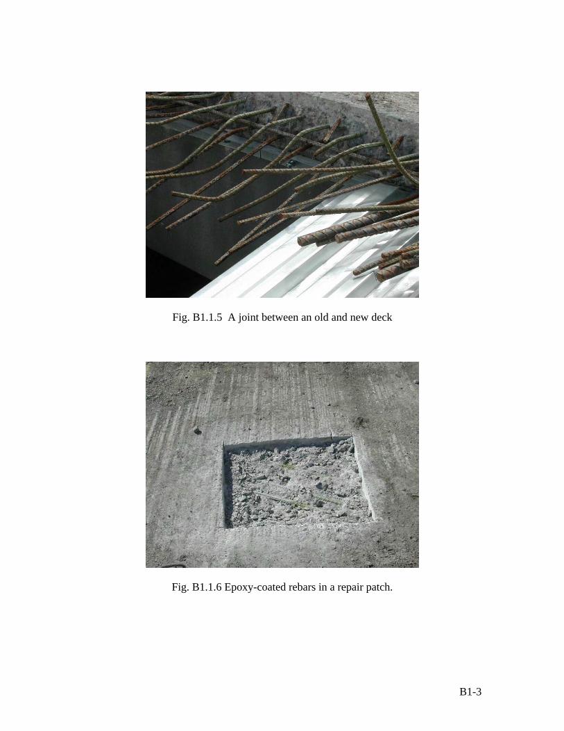
Fig. B1.1.5 A joint between an old and new deck
Fig. B1.1.6 Epoxy-coated rebars in a repair patch.
B1-3

B1.2 I-25 over Orchard Rd.
Fig. B1.2.1 Bridge on I-25 over Orchad
Fig. B1.2.2 Asphalt with membrane overlay
B1-4

Fig. B1.2.3 Delamination test – heavy delamination was encountered
Fig. B1.2.4 Corroded steel on the concrete deck
B1-5

Fig. B1.2.5 Some black bars (1970’s part) are in good condition.
Fig. B1.2.6 Severe corrosion of steel bars
B1-6

Fig. B1.2.7 Large area of corroded steel bars in the deck
Fig. B1.2.8 Leakage on the bottom deck - on the construction joint
B1-7
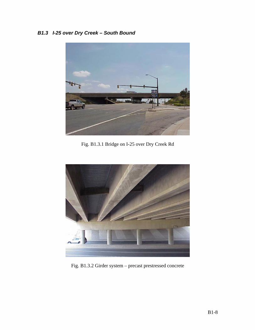
B1.3 I-25 over Dry Creek – South Bound
Fig. B1.3.1 Bridge on I-25 over Dry Creek Rd
Fig. B1.3.2 Girder system – precast prestressed concrete
B1-8

Photo A.3.3 Bridge deck – asphalt overlay
B1-9

B1.4 Belleview – North Bound
Fig. B1.4.1 Bridge on I-25 over North Bound Belleview
Fig. B1.4.2 A marked area of delamination on the deck – tested using hammer sound
B1-10

Fig. B1.4.3 Slab floor is heavily damaged (a big hole in the deck)
Fig. B1.4.4 Severe corrosion of main reinforcement steels
B1-11
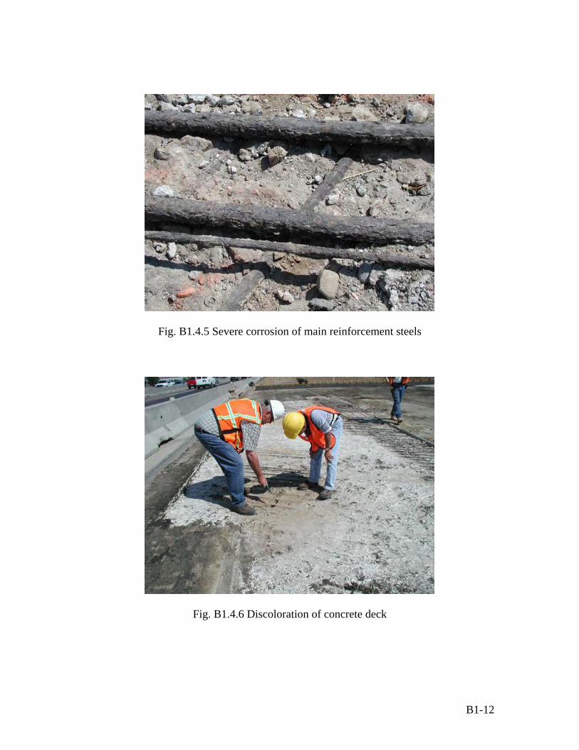
Fig. B1.4.5 Severe corrosion of main reinforcement steels
Fig. B1.4.6 Discoloration of concrete deck
B1-12

Fig. B1.4.7 Bottom deck view - seepage of water around the construction joint
Fig. B1.4.8 A major cracks on the bottom deck
B1-13
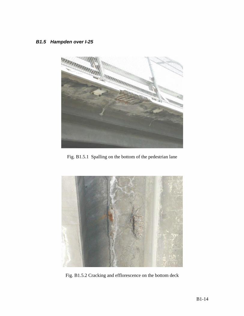
B1.5 Hampden over I-25
Fig. B1.5.1 Spalling on the bottom of the pedestrian lane
Fig. B1.5.2 Cracking and efflorescence on the bottom deck
B1-14

Fig. B1.5.3 Efflorescence on the main beam (girder)
Fig. B1.5.4 Severe cracking
B1-15

Fig. B1.5.5 efflorescence on the main beam (girder)
Fig. B1.5.6 Severe spalling and corrosion on the main beam (girder)
B1-16

Fig. B1.5.7 Severe spalling on the bottom deck
B1-17

B1.6 Emerson over I-25
Fig. B1.6.1 Emerson over I-25 – under demolition process
Fig. B1.6.2 Emerson over I-25 – under demolition process
B1-18
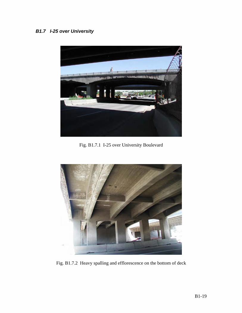
B1.7 I-25 over University
Fig. B1.7.1 I-25 over University Boulevard
Fig. B1.7.2 Heavy spalling and efflorescence on the bottom of deck
B1-19

Fig. B1.7.3 Heavy spalling and corrosion on one of the girders
Fig. B1.7.4 Corrosion of steel and spalling of concrete in another girder
B1-20

Fig. B1.7.5 Severe cracking in one of the girders near efflorescence areas
Fig. B1.7.6 Bridge decks under demolition process
B1-21
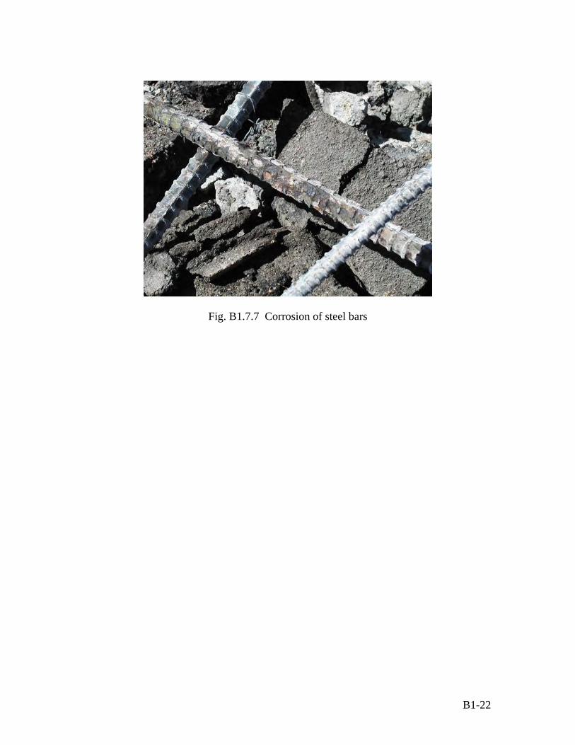
Fig. B1.7.7 Corrosion of steel bars
B1-22

Appendix B2 – TREX Bridges - Chloride Concentration Profiles
B2.1. Dry Creek over I-25
Dry Creek - Shoulder Lane
0.000
0.002
0.004
0.006
0.008
0.010
0.012
0.014
0.5 1 1.5 2
Depth (inch)
Chlo
ride
conc
entra
tion
(%)
Dry Creek - Driving Lane
0.0000.0010.0010.0020.0020.0030.0030.0040.0040.0050.005
0.5 1 1.5 2
Depth (inch)
Chlo
ride
conc
entra
tion
(%)
B2-1

B2.2. Emerson Street over I-25
Emerson - Right side of Column
0.000.020.040.060.080.100.120.140.16
0 0.5 1 1.5Depth (inch)
Chl
orid
e co
ncen
trat
ion
(%)
2
B2.3. I-25 over University
University
0.03
0.04
0.05
0.06
0.07
0.0 0.5 1.0 1.5 2.0Depth [in]
Chl
orid
e co
ncen
trat
ion
(%)
B2-2

Appendix C. Inspection Results (photos and crack mapping)
C.1 The Bridge on SH85 in Greeley
Bridge on SH 85
Fig C.1.1 The location of the bridge
C-1

Fig C.1.2 The bridge on SH 85 Fig C.1.3 The bridge on the SH 85 in New asphalt overlay with galvashield Greeley corrosion protection
Fig C.1.4 Efflorescence on the bottom Fig C.1.5 Efflorescence and corrosion damage of the bridge deck on the lower elevation (slope) of the bridge
Fig C.1.6 Cracks on the pier and Fig C.1.7a Spalling on a pier before the salt deposited on the pier cap placement of asphalt overlay on the deck
C-2

Fig C.1.7b Severe spalling on the same pier after the placement of asphalt overlay on the deck
Fig C.1.8 Efflorescence on the bottom Fig C.1.9 Salt deposited on the pier cap of bridge deck and connection between girder and deck
Fig. C.1.10 Concrete cores of 3 inch diameter Fig. C.1.11 Steel bars in concrete cores of three inch diameter
C-3
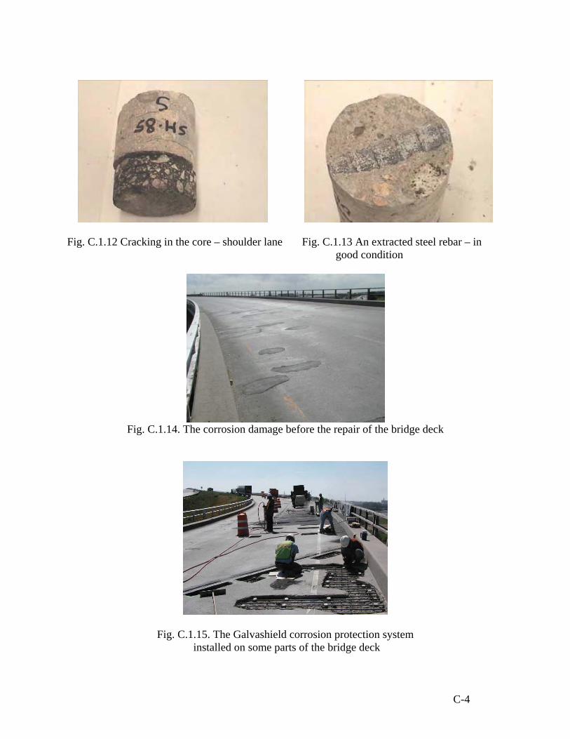
Fig. C.1.12 Cracking in the core – shoulder lane Fig. C.1.13 An extracted steel rebar – in good condition
Fig. C.1.14. The corrosion damage before the repair of the bridge deck
Fig. C.1.15. The Galvashield corrosion protection system installed on some parts of the bridge deck
C-4

C.2 The bridge on SH34-Business Route in Greeley
Bridge location on SH 34-Bussiness Route
Fig. C.2.1 The bridge location on SH-34 Business Route over South Platte River
Fig. C.2.2 The bridge on SH 34 Business Route Fig. C.2.3 The bridge surface on SH 34 (New asphalt overlay with galvashield
corrosion protection)
C-5

Fig. C.2.3 Cracking and spalling on the pier cap Fig. C.2.4 Cracking on the pier cap
Fig. C.2.5 Spalling on the pier cap Fig C.2.6 Efflorescence on the bottom and pier cap
Fig. C.2.7 Concrete cores of 3 inch diameter Fig. C.2.8 The severe corrosion damage before the repair of the bridge deck
C-6

C.3 Wolfensburger Rd. WB over I-25
n
Fig. C.3.1 The location of
Bridge locatio
the bridge
C-7
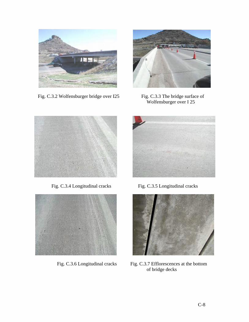
Fig. C.3.2 Wolfensburger bridge over I25 Fig. C.3.3 The bridge surface of
Wolfensburger over I 25
Fig. C.3.4 Longitudinal cracks Fig. C.3.5 Longitudinal cracks
Fig. C.3.6 Longitudinal cracks Fig. C.3.7 Efflorescences at the bottom of bridge decks
C-8

Fig. C.3.8 Efflorescence on the bottom deck Fig. C.3.9 An epoxy-coated rebar in good condition
Fig. C.3.10 Cracks around the bridge abutment Fig. C.3.11 A piece of ECR
Fig. C.3.12 A close look on the epoxy- Fig. C.3.13 Cracking in the core coated steel rebar – in good condition
C-9

Fig. C.3.14 Location of the concrete core and longitudinal cracks on Wolfensburger over I25
EAST
t
Notes:
C
120 f
t 90 ft
60 f t 30 fWEST
rack width varies from 0.009 – 0.013 in
= Coring location
C-10

C.4 Wolfensburger Rd. WB over PLUM Creek
Bridge location
Fig. C.4.1 The location of the bridge
C-11

Fig. C.4.2 Wolfensburger over Plum Creek Fig. C.4.3 The bridge surface of Wolfensburger Road WB over Plum Creek
Fig. C.4.4 A bottom view of a pier Fig. C.4.5 A bottom view of a pier cap and girder systems cap and girder systems
Fig. C.4.6 Longitudinal cracks Fig. C.4.7 Longitudinal cracks
C-12

Fig. C.4.8 Transverse cracks
Fig. C.4.9 A core hole in the concrete deck
C-13

Fig. C.4.10 Location of the concrete core and cracks around the core on Wolfenburger over Plum Creek
EAST
t
Notes:
-
-
120 f
t 90 ft
60 f t 30 fWEST
Crack width varies from 0.003 – 0.005 in
= Coring location
C-14

C.5 Kettle Creek Bridge on SH-83 in Colorado Springs
Fig. C.5.1 The loca
Bridge location
tion of the bridge
C-15
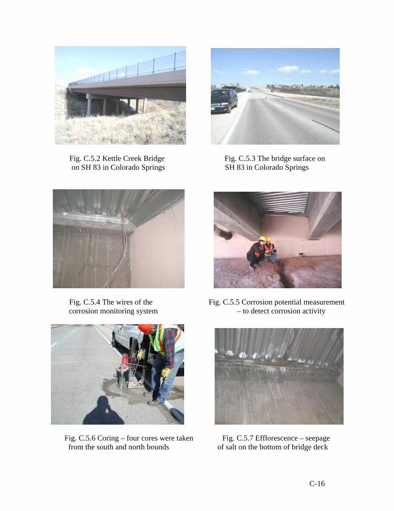
Fig. C.5.2 Kettle Creek Bridge Fig. C.5.3 The bridge surface on on SH 83 in Colorado Springs SH 83 in Colorado Springs
Fig. C.5.4 The wires of the Fig. C.5.5 Corrosion potential measurement
corrosion monitoring system – to detect corrosion activity
Fig. C.5.6 Coring – four cores were taken Fig. C.5.7 Efflorescence – seepage from the south and north bounds of salt on the bottom of bridge deck
C-16

Fig. C.5.8 Transverse cracks Fig. C.5.9 Transverse cracks on shoulder lane – South Bound
Fig. C.5.10 Core samples – from the Fig. C.5.11 Crack depth reached the
south and north Bounds (ECR and black bar) level of rebar - North Bound
Fig. C.5.12 A close look on the black bar – Rust deposited on the concrete (Concrete with the corrosion inhibitor)
C-17

r s
t
t
t
t
Fig
120 f
.
90 f
60 f
30 f
C.5.13 Locati
Shoulde
ons of concrete cores an(up to 120 ft
Driving Lane
d cracks around the cores on the south bound from the north)
C-18

s r
t
F
Notes:
• B •
120 f
t
ig
o
90 f
t 60 f t 30 f. C.5.14 Crack mapping and locations of concrete(up to 120 ft from the sou
ttom-deck crack mapping was not performed
= Coring location
Shoulde
Traffic Lanecores on the north bound lane th)
C-19

C.6 The Bridge on I-70EB on MP 293.6
Bridge Location
Fig. C.6.1 The location of the bridge
C-20

Fig. C.6.2 F-18-AQ structure Fig. C.6.3 The surface of F-18-AQ structure
Fig. C.6.4 The cathodic protection system Fig. C.6.5 The control box for the
cathodic protection system
Fig. C.6.6 The field records (log form) Fig. C.6.7 The transverse cracking of the cathodic protection system
C-21

Fig. C.6.8 Transverse crack with Fig. C.6.9 Severe spalling on the sub-beam width varying from 0.016-0.030 in
Fig. C.6.10 Cracks on a pier cap Fig. C.6.11 Cores extracted from the
shoulder and driving lanes
C-22

C.7 The Bridge on I-70 on MP 294.7
Bridge location
Fig. C.7.1 The location of the bridge
C-23

Fig. C.7.2 The three span Fig. C.7.3 The bridge surface
bridge on I70 mp 294.7
Fig. C.7.4 The girder system Fig. C.7.5 Cracks on one of the pier caps – deck slab on grid beams
Fig. C.7.6 Cracks on the deck slab Fig. C.7.7 Cracks on the deck slab
C-24

Fig. C.7.8 The concrete spalling with Fig. C.7.9 Concrete cores of 4 inch diameter efflorescence on one of the pier caps
Fig. C.7.10 The delamination in the concrete overlay
C-25

C.8 I-70 EB over Moss St.
Fig. C.8.1 The location o
Bridge Location
f I-70 EB over Moss St
C-26

Fig. C.8.2 The side view of Fig. C.8.3 The bottom view the bridge on I70-over Moss St of the girder system
Fig. C.8.4 Cracks on the Fig. C.8.5 A longitudinal asphalt overlay (0.013. inch crack) crack on the asphalt overlay
Fig. C.8.6 Efflorescence with crack Fig. C.8.7 Efflorescence with crack pattern on the bottom of the slab (I) pattern on the bottom of the slab (II)
C-27

Fig. C.8.8 Cracks on the transverse girder Fig. C.8.9 Efflorescence on the shoulder
Fig. C.8.10 Concrete corings
Fig. C.8.11 Concrete cores with a steel bar Fig. C.8.12 Concrete cores taken from the driving lane
C-28

Fig. C.8.13 A corroded steel Fig. C.8.14 Damaged asphalt membrane bar (in the shoulder lane) overlay (cracked area - driving lane)
C-29

C.9 Yosemite over I-25
Bridge location
Fig. C.9.1 The location of the bridge: Yosemite over I-25
Fig. C.9.2 A side view Fig. C.9.3 The flow of deicing salt of Yosemite over I-25 on the overhang structure
C-30

Fig. C.9.4 Efflorescence on Fig. C.9.5 The flow of deicing the overhang structure salt near construction joint
Fig. C.9.6 Concrete cores Fig. C.9.7 A concrete core extracted from the driving lane extracted from the shoulder lane
’
Fig. C.9.8 No signs of corrosion rust/deposit found on the concrete cover on an epoxy-coated rebar
C-31

Appendix D - Chloride Profiles of the Inspected Bridges D.1 SH85 in Greeley Shoulder Lane
SH85 - Shoulder Lane
0.000
0.010
0.020
0.030
0.040
0.050
0.060
0.5 1 1.5 2
Depth (inches)
Chlo
ride
conc
entra
tion
(%)
Driving Lane
SH85- Driving Lane
0.000
0.0200.040
0.060
0.080
0.1000.120
0.140
0.5 1 1.5 2
Depth (inches)
Chlo
ride
conc
entra
tion
(%)
D-1

D.2 SH34 Business Route in Greeley Shoulder Lane
SH34 - Shoulder Lane
0.000
0.050
0.100
0.150
0.200
0.250
0.5 1 1.5 2
Depth (inches)
Chlo
ride
conc
entra
tion
(%)
Driving Lane
SH34 - Driving Lane
0.0000.0100.0200.0300.0400.0500.0600.0700.0800.090
0.5 1 1.5 2
Depth (inches)
Chlo
ride
conc
entra
tion
(%)
D-2

D.3 Wolfensburger over I-25
Wolfensburger over I-25
0.0000.0500.1000.1500.2000.2500.3000.3500.400
0.5 1 1.5 2
Depth (inches)
Chlo
ride
conc
entra
tion
(%)
D-3

D.4 Wolfensburger over I-25
Wolfensburger over Plum Ck.
0.000
0.050
0.100
0.150
0.200
0.250
0.5 1 1.5 2
Depth (inches)
Chlo
ride
conc
entra
tion
(%)
D-4

D.5 Kettle Creek in Colorado Springs South Bound – Shoulder Lane
Kettle Creek SB -Shoulder Lane
0.0000.0200.0400.0600.0800.1000.1200.1400.1600.180
0.5 1 1.5 2
Depth (inches)
Chlo
ride
conc
entra
tion
(%)
South Bound – Driving Lane
Kettle Creek SB - Driving Lane
0.0000.0200.0400.0600.0800.1000.1200.1400.160
0.5 1 1.5 2
Depth (inches)
Chlo
ride
conc
entra
tion
(%)
D-5

Kettle Creek (cont’d……) North Bound – Shoulder Lane
Kettle Creek NB - Shoulder Lane
0.000
0.050
0.100
0.150
0.200
0.250
0.5 1 1.5 2
Depth (inches)
Chlo
ride
conc
entra
tion
(%)
North Bound – Driving Lane
Kettle Creek NB - Driving Lane
0.000
0.050
0.100
0.150
0.200
0.250
0.300
0.5 1 1.5 2
Depth (inches)
Chlo
ride
conc
entra
tion
(%)
D-6

D.6 I70 MP 293.6 Shoulder Lane
I70-Mp 293.6 - Shoulder Lane
0.000
0.050
0.100
0.150
0.200
0.5 1 1.5 2
Depth (inches)
Chlo
ride
conc
entra
tion
(%)
Driving Lane
I70-Mp 293.6 - Driving lane
0.0000.0200.0400.0600.0800.1000.1200.1400.160
0.5 1 1.5 2
Depth (inches)
Chlo
ride
conc
entra
tion
(%)
D-7
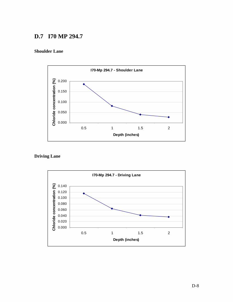
D.7 I70 MP 294.7 Shoulder Lane
I70-Mp 294.7 - Shoulder Lane
0.000
0.050
0.100
0.150
0.200
0.5 1 1.5 2
Depth (inches)
Chlo
ride
conc
entra
tion
(%)
Driving Lane
I70-Mp 294.7 - Driving Lane
0.000
0.0200.040
0.060
0.080
0.1000.120
0.140
0.5 1 1.5 2
Depth (inches)
Chlo
ride
conc
entra
tion
(%)
D-8

D.8 I70 over Moss St Shoulder Lane
I-70 EB over Moss St. - Shoulder Lane
0.000
0.005
0.010
0.015
0.020
0.025
0.030
0.5 1 1.5 2
Depth (inches)
Chlo
ride
conc
entra
tion
(%)
Driving Lane
I-70 EB over Moss St. - Driving Lane
0.000
0.0050.010
0.015
0.020
0.0250.030
0.035
0.5 1 1.5 2
Detph (inches)
Chlo
ride
conc
entra
tion
(%)
D-9

D.9 Yosemite over I-25 Shoulder Lane
Yosemite over I-25 - Shoulder Lane
0.000
0.0020.004
0.006
0.008
0.0100.012
0.014
0.5 1 1.5 2
Depth (inches)
Chlo
ride
conc
entra
tion
(%)
Driving Lane
Yoseimite over I-25 - Driving Lane
0.0000.0010.0020.0030.0040.0050.0060.007
0.5 1 1.5 2
Depth (inches)
Chlo
ride
conc
entra
tion
(%)
D-10