Performance Evaluation of LTE-M NBIoT in IoT to Blockchain ...
42
Performance Evaluation of LTE-M NBIoT in IoT to Blockchain Transmissions Cepilov Ile Cugnasco-Gerra, Ticino, Switzerland Student ID: 13-929-740 Supervisor: Sina Rafati, Eryk Schiller Date of Submission: August 20, 2019 University of Zurich Department of Informatics (IFI) Binzmühlestrasse 14, CH-8050 Zurich, Switzerland ifi I NDEPENDENT S TUDY – Communication Systems Group, Prof. Dr. Burkhard Stiller
Transcript of Performance Evaluation of LTE-M NBIoT in IoT to Blockchain ...

Performance Evaluation of LTE-MNBIoT in IoT to Blockchain
Transmissions
Cepilov IleCugnasco-Gerra, Ticino, Switzerland
Student ID: 13-929-740
Supervisor: Sina Rafati, Eryk SchillerDate of Submission: August 20, 2019
University of ZurichDepartment of Informatics (IFI)Binzmühlestrasse 14, CH-8050 Zurich, Switzerland ifi
IND
EP
EN
DE
NT
ST
UD
Y–
Com
mun
icat
ion
Sys
tem
sG
roup
,Pro
f.D
r.B
urkh
ard
Stil
ler
Independent StudyCommunication Systems Group (CSG)Department of Informatics (IFI)University of ZurichBinzmühlestrasse 14, CH-8050 Zurich, SwitzerlandURL: http://www.csg.uzh.ch/

Abstract
Eine wachsende Anzahl von ”Internet of Things” (IoT) - Geraten wird kompakter undenergieeffizienter. In meiner Bachelor Arbeit habe ich aufgezeigt, was mit energieeffizientenGeraten moglich ist, die mit der Low Power Wide Area Network (LPWAN) und mit derBazo Blockchain arbeiten. In dieser Arbeit fokussiere ich Gerate, die auf der popularen”Long Term Evolution” (LTE) Technologie basieren, aber fur IoT Anwendungen adaptiertsind, wie zum Beispiel LTE-m. In einem ersten Schritt gebe ich einen Uberblick uber dieIoT-Blockchain Architektur. In einem zweiten Schritt zeige ich auf, wie IoT-Gerate in diebereits existierende Bazo Blockchain integriert werden konnen. Schliesslich vergleiche ichdie LoRa mit der LTE-m Architektur, mit einem Fokus auf Energieeffizienz und DatenOverhead.
An increasing number of devices belonging to the domain of the ”Internet of Things” (IoT)is becoming more compact and energy efficient. In my bachelor thesis, I have shown whatis possible to do with energy efficient devices working with the Low Power Wide AreaNetwork (LPWAN) and the Bazo blockchain. In this study, I am targeting devices thatare based on the more popular technology ”Long Term Evolution” (LTE) but adapted toIoT applications, i.e. LTE-m. In a first step I am giving an overview of the IoT-Blockchainarchitecture, in a second step I am showing the process of integrating those IoT devices inthe already existing Bazo Blockchain. At the end, I compare the LoRa with the LTE-marchitecture focussing on power efficiency and data overhead.
i

ii

Contents
Abstract i
1 Introduction 1
1.1 Motivation . . . . . . . . . . . . . . . . . . . . . . . . . . . . . . . . . . . . 1
1.2 Description of Work . . . . . . . . . . . . . . . . . . . . . . . . . . . . . . 1
1.3 Work Outline . . . . . . . . . . . . . . . . . . . . . . . . . . . . . . . . . . 2
2 Related Work and Background 3
2.1 Internet of Things and the Bazo Blockchain . . . . . . . . . . . . . . . . . 3
2.1.1 Bazo Client . . . . . . . . . . . . . . . . . . . . . . . . . . . . . . . 4
2.1.2 Arduino Cellular IoT Application Shield . . . . . . . . . . . . . . . 4
3 Design and Implementation 5
3.1 Design . . . . . . . . . . . . . . . . . . . . . . . . . . . . . . . . . . . . . . 5
3.1.1 IoT Architecture . . . . . . . . . . . . . . . . . . . . . . . . . . . . 5
3.1.2 IoT Transaction overview . . . . . . . . . . . . . . . . . . . . . . . 7
3.2 Implementation . . . . . . . . . . . . . . . . . . . . . . . . . . . . . . . . . 7
3.2.1 Mandatory adaptations in the Sixfab CellularIoT Shield library . . 7
3.2.2 Arduino Sketch for LTE-m Nodes . . . . . . . . . . . . . . . . . . . 11
3.2.3 UDP packet listener on Bazo Client . . . . . . . . . . . . . . . . . . 12
iii
iv CONTENTS
4 Evaluation 17
4.1 Security Aspects . . . . . . . . . . . . . . . . . . . . . . . . . . . . . . . . 17
4.2 Arduino LTE-m CellularIoT Shield . . . . . . . . . . . . . . . . . . . . . . 17
4.3 Energy efficiency of LTE-m . . . . . . . . . . . . . . . . . . . . . . . . . . 18
5 Summary and Conclusions 21
Bibliography 23
Abbreviations 25
List of Figures 25
List of Tables 27
Listings 29
A Installation Guidelines 33
A.1 Prerequisites . . . . . . . . . . . . . . . . . . . . . . . . . . . . . . . . . . . 33
A.2 LTE-m Arduino sketch . . . . . . . . . . . . . . . . . . . . . . . . . . . . . 33
A.3 Bazo Miner . . . . . . . . . . . . . . . . . . . . . . . . . . . . . . . . . . . 34
A.4 Bazo Client . . . . . . . . . . . . . . . . . . . . . . . . . . . . . . . . . . . 35

Chapter 1
Introduction
1.1 Motivation
Nowadays, many transmission standard are addressing the IoT market with different ap-proaches. We have the Long Term Evolution (LTE) cat. M/M1, the enhanced NarrowBand IoT (NB-IoT) and the Extended Coverage GSM IoT (EC-GSM-IoT). Every stan-dard has its advantages and disadvantages.NB-IoT is an alternative that, thanks to reduced complexity, has a lower cost at the ex-pense of decreasing data rate. Indeed, the bandwidth is up to 200 kbps in both directions.The involvement of the mobile operator in the process of developing private IoT networksis required when dealing with Cellular IoT. The bands on which those devices operate areactually licensed bands.
1.2 Description of Work
In this independent study, the first goal is to allow IoT devices, which use LTE-M, to senddata to our Bazo blockchain. The version of the Bazo blockchain we are using for thisstudy already supports IoT transactions and therefore it does not have to be adapted.A network of simple topology is going to be implemented with only one LTE-M nodeprovided with a SIM (Subscriber Identity Module) card.
This node is going to directly send data to the Bazo Client using either the TransmissionControll Protocoll (TCP) or the User Datagram Protocol (UDP).On the Bazo client side, a listener will be implemented in order to allow the communicationbetween the two points.
The second task of the study is going to be the energy efficiency evaluation of LTE-Mwith respect to the version implemented using LoRa nodes.The analysis is going to be based on the signed packets sent to the Bazo blockchain. More-over, an efficiency measure in terms of data overhead, energy consumption and transmis-sion mechanism implementation is going to be provided.
1

2 CHAPTER 1. INTRODUCTION
Overall, the IoT adaptation architecture has to be appropriately modified to acknowledgea different protocol stack of the LTE-M network, i.e. IoT devices using the IP stack totransport information instead of the LoRaWAN-based TTN network.
1.3 Work Outline
In Chapter two an introduction to the previously implemented IoT architecture is given.Required hardware component utilized are also going to be part of that chapter.Chapter three contains two main parts, the first one shows the designs of all the mainsystem components analyzed and developed during this study and compared to the LoRaarchitecture. The second one contains the implementations that had to be done. Notonly to create the whole system but also to improve the existing libraries provided by theproducer of the Arduino CeullularIoT Shield.Chapter four contains the evaluation part of this study. The most important part of thischapter are going to be the energy efficiency compared to the LoRa architecture and thedata overhead. Chapter five summarizes and concludes the report.

Chapter 2
Related Work and Background
This section is going to provide an overview of an existing IoT approach with a blockchainand this study is going to be based specifically on it. A classification of used and existinghardware, as well as communication systems useful for this study, is going to be provided
2.1 Internet of Things and the Bazo Blockchain
As a starting point, we are going to take the bachelor thesis based on LoRa nodes whichcan issue IoT transaction to the Bazo Blockchain [9].Bazo is a blockchain being currently under develop at the University of Zurich and incollaboration with the ”HSR Hochschule fur Technik Rapperswil”. It is written in theprogramming language ”GO” and based on Proof-of-Stake [10]. It has been adapted toaccomodate IoT transactions and in order to accomplish that, the cryptographic functionused was changed in a more light-weight and IoT suitable Elliptic Curve Digital Signa-ture Algorithm (ECDSA), namely Ed25519 [3]. This new cryptographic function is alsocompatible with the arduino cryptography library [2].
Because of the limiting factor of the LoRa technology explained here [9], the alreadyimplemented version needed a management HUB, called TTN-Plugin. The TTN-pluginis in charge of coordinating the incomplete transactions coming from each node and re-construct them. Once reconstructed and validated, it forwards them to the Bazo Clientwhich is then going to broadcast each transaction to the Miners of the network. In orderto reduced the overhead of the signature and the actual data collected, the TTN-plugincan also aggregate multiple packets and thus optimize the whole architecture.That approach works well for nodes based on the LoRa protocol, since it allows such arestricting technology to issue IoT transaction. In this study, we are going to issue a fullIoT transaction without any intermediary, i.e. there will not be any management HUB tohelp us in achieving this and to do that, we are going to use a more powerful technology,namely LTE-m.
3

4 CHAPTER 2. RELATED WORK AND BACKGROUND
2.1.1 Bazo Client
A fundamental part of this study is going to be the Bazo Client. Since the Bazo Minersupports IoT transactions and communicates just between miners and Bazo clients, nochange or implementation is going to be required. As for the Bazo Client, we will haveto introduce the possibility to gather data from a LTE-m enabled node. We are notgoing to use the already implemented Representational State Transfer (REST) Applicationprogramming interface (API). Since we are going to implement everything over the UDPprotocol, we will need to implement a UDP packet listener and integrate it on the client’sside, so that it can simultaneously serve LoRa nodes as well as LTE-m nodes.
2.1.2 Arduino Cellular IoT Application Shield
Together with an Arduino Mega 2560 [5], we couple an LTE IoT Shield. Thanks to theexpanded memory of the Aruino Mega 2560, we can manage and process all IoT Transac-tions without many hassles and thanks to the IoT Shield we are able to send data throughthe IP stack.
The Cellular IoT Shield [6] has combined LTE technology Cat.M1, Cat.NB1 (Nb-IoT)and eGPRS. This shield is based on the Quectel’s BG96 Module [7], which offers a max-imum data rate of 375Kbps downlink and 375Kbps uplink. Moreover, it features globalfrequency bands and ultra-low power consumption.Some of the many key applications of this shield are in smart farming/cities sensor, In-ternet of Things sensors, agricultural and environmental monitoring and many others.

Chapter 3
Design and Implementation
3.1 Design
This section explains the design decision taken to enable the communication betweenLTE-m nodes and the Bazo client. We will explain how IoT devices communicate to theblockchain and we will also show a specific overview of how a full IoT transaction can beissued from a LTE Node.
3.1.1 IoT Architecture
Figure 3.1 is taken from our previous study [9] and adapted for LTE-m nodes. It actuallyshows the agnostic overview of the IoT Architecture mainly developed for LoRa nodes.The system is designed to be compatible across most common system without requiringany special adaptations. Indeed, if we compare both version of it, we will see that thereis only one small difference.As before, we have an IoT Device, in this case based on LTE-m, which has a BlockchainWallet that enables IoT transactions to be issued to the Bazo blockchain. An edge node(Bazo client), placed on the other side as a receiver, gets the transactions before they canreach the Bazo blockchain and thus the miners.Unlike in our previous version, we do not have a management hub which is responsiblefor coordinating all IoT devices across the network before being able to forward theirtransactions.Indeed, our LTE-m nodes are able to issue full IoT transactions directly to a Bazo clientand thus removing the necessity of any intermediary.
5

6 CHAPTER 3. DESIGN AND IMPLEMENTATION
LTE
BlockchainClient
IoT Device
BlockchainWallet
Input/Output
IPStack
Edge Node
Internet
NetworkAdapter
NetworkAdapter
LTEAdapters
MonitoredSupply Chain
Blockchain
Figure 3.1: Agnostic IoT architecture adapted from [9]

3.2. IMPLEMENTATION 7
3.1.2 IoT Transaction overview
In this brief section, we are going to have a look at what part are being transmitted whensending an IoT transaction.
Figure 3.2 shows which data is actually sent. If we compare this version with the architec-ture used with LoRa we can notice that the transmission pattern is completely different.With LoRa, we had to send only as few data as possible. This implied sending only apublic key, split the signature of the data into two packets and split the data as well intomultiple packets. Thanks to the much more powerful technology LTE-m, we are ableto issue a single IoT transaction with all the required parameters. As opposed to theLoRa version where the transaction fee and counter had to be static, here we can actuallychange them and have them dynamic as well.We are able to send all the required fields and thus even improve security aspects linkedto the double spending attack [8], solved thanks to a transaction counter (TxCnt).
BazoBazo Client
UD
P pa
cket
list
ener
32B Pk's Issuer (Node)
1B Header
int32 TxCnt
int64 TxFee
32B Address recipient
64B Signature
Data
Figure 3.2: LTE-m HW Wallet for a full IoT Transaction
3.2 Implementation
This section shows the main implementation’s steps taken to enable the communicationbetween LTE-m nodes and the Bazo client. We will explain how IoT devices communicateto the blockchain through the protocol UDP and we will also show required changes inthe official Sixfab Arduino CellularIoT library to allow a correct transmission of the data.
3.2.1 Mandatory adaptations in the Sixfab CellularIoT Shieldlibrary
Similar to the LMIC library [1] used for LoRa nodes, we have had encountered manyproblems when trying to send more data. We experienced two different behaviors; eitherthe node will crash or freeze and a hard reboot was required or when sending data, notthe whole data was actually sent. In this section, we are going to explain those issues andshow how to fix them.

8 CHAPTER 3. DESIGN AND IMPLEMENTATION
The first problem with the device freezing or rebooting was solved by modifying the officialSixfab library which can be found on github here [11].First of all, we have to open the file named Sixfab_CellularIoT.cpp. At line 59 wecan see that some constants are defined. This constants are actually too small whensending more than around 115 Bytes and the devices will crash or freeze. Therefore, wecan modify them as follows:
1 // Constants
2 #define TIMEOUT 3000
3 #define IP_ADDRESS_LEN 30
4 #define DOMAIN_NAME_LEN 50
5 #define PORT_NUMBER_LEN 8
6 #define AT_COMM_LEN 2000
7 #define AT_RESPONSE_LEN 200
8 #define DATA_COMPOSE_LEN 200
9 #define DATA_LEN_LEN 200
Listing 3.1: Constant for Sixfab Cellular IoT library
Moreover, not only those have to be changed, but if we scroll down to line 640, we cansee that the variables compose and url are also constrained.Compose is used when wanting to send AT commands and url is used when wanting tosend either a POST or GET request.In our case, since we are using the protocol UDP , we need to change the variable composeso that we are able to send more data.While working on solving this issues, we tried to execute HTTP requests, that’s why weeven modified the variable url.
1 private:
2 char compose [999];
3 char url [200];
Listing 3.2: Private value for Sixfab Cellular IoT library
After modifying the library and being able to send as much data as by us required, thenode kept freezing. After some debugging, we discovered that the node was not actuallyfreezing, it was just stuck in an infinite while loop.
Now, let’s have a look at the functions we are using to try to explain the while loop.First of all, we have to open the file named Sixfab_CellularIoT.h. There, we can findthe function named sendDataUDP(const char *data).
1 // fuction for sending data via udp.
2 void SixfabCellularIoT :: sendDataUDP(const char *data)
3 {
4 clear_compose ();
5 char data_len [10];
6 sprintf(data_len , "%d", strlen(data));
7
8 strcpy(compose , "AT+QISEND=1,");

3.2. IMPLEMENTATION 9
9 strcat(compose , data_len);
10 strcat(compose , " ,\"");
11 strcat(compose , ip_address);
12 strcat(compose , "\",");
13 strcat(compose , port_number);
14
15 sendATComm(compose ,">");
16 sendDataComm(data ,"OK\r\n");
17
18 clear_compose ();
19 }
Listing 3.3: Send data UDP function in the Sixfab CellularIoT library
In this function, we have done a small modification:Instead of calling twice sendAtComm, we call sendDataComm when we do not want to senda command but we want to actually send data.
Now, let’s move to the sendDataComm function and see where the real problem is.
1 // function for sending data to BG96_AT.
2 const char* SixfabCellularIoT :: sendDataComm(const char *command , const char *
desired_reponse)
3 {
4 uint32_t timer;
5 char response[AT_RESPONSE_LEN ]; // module response for AT commands.
6 memset(response , 0 , AT_RESPONSE_LEN);
7 BG96_AT.flush();
8
9 BG96_AT.print(command);
10
11 timer = millis ();
12 while(true){
13 if(millis ()-timer > 20000){
14 BG96_AT.print(command);
15 timer = millis ();
16 }
17 char c;
18 int i = 0;
19
20 while(BG96_AT.available ()){
21 c = BG96_AT.read();
22 DEBUG.write(c);
23 response[i++]=c;
24 delay (5);
25 }
26 if(strstr(response , desired_reponse)){
27 return response;
28 memset(response , 0 , strlen(response));
29 break;
30 }
31 }
32 }
Listing 3.4: Send data command in Sixfab CellularIoT library
As we can see, in this code snippet above at line 12 there is a while(true) loop thatshould actually never be used. The only way to break this loop is to get into the if

10 CHAPTER 3. DESIGN AND IMPLEMENTATION
condition at line 16. The problem arises when sending too much data:The response is actually bugged and we will never be able to enter into it and thus breakthe loop.
The solution is quite simple: we just change the condition in the while loop and put atimeout as follows:
1 while(millis ()-timer < 20000){
2 ...
3 ...
4 }
Listing 3.5: Avoid an infinite while loop in the Sixfab CellularIoT library
Only at this point, we are able to send much more data through the CellularIoT Shieldfrom Sixfab.The problem regarding the loss of data while sending it, is still related to the library butwe were not able to change it. Instead, we found a workaround which works perfectly fine(without any loss of data) and has very little overhead.The strange behavior appears when sending raw bytes and more precisely, when the datawe send contains a byte equals to 0. Instead of sending the whole buffer of bytes, the datais split right where the 0 is and the rest does not get sent.The 0 gets interpreted as an escape sequence, i.e. as the terminating character. Moreover,some weird behavior start happening with the Shield, i.e. some random data is sent rightafter it.
A solution is to save how many 0’s our data contains, save their position in the datasomewhere else and replace them with their index in the array. When sending the data,append the number of 0’s, their positions and the modified data. Then, on the receiverside, just replace everything with the following algorithm implemented in javascript:
1 l e t nrOfZeros = rawData [ 0 ] ;2 l e t z e r o sPo s i t i o n = rawData . s l i c e (1 , nrOfZeros ) ;3
4 l e t over f l ow = 0 ;5 l e t previousByte = z e r o sPo s i t i o n [ 0 ] ;6 f o r ( l e t i = 0 ; i < z e r o sPo s i t i o n . l ength ; i++){7 l e t tmpByte = ze r o sPo s i t i o n [ i ] ;8 i f ( previousByte>tmpByte ) {9 over f l ow++;
10 }11 previousByte = tmpByte ;12 const zeroIndex = tmpByte+(255∗ over f l ow )13 rawData [ zeroIndex ] = 0 ;14 }
Listing 3.6: Reconstruct the received data with 0’s
We take the number of zeros we know we will have, we extract the array based on that num-ber and then we simply loop into it and we overwrite the value with rawData[zeroIndex]
= 0.The overflow variable is required when we send from the node data which is longer than256 Bytes. This is necessary when there is a 0 value after the 255th position, since thenode will not send any number bigger than 255 but it will just start again from 0. There-fore, we simply check the array and if we notice that we went back from 255, we increase

3.2. IMPLEMENTATION 11
our overflow and so we are able to extract the correct index greater than 255.
This method works, but it’s actually really cumbersome to manage when sending dif-ferent variables and the intention is to extract each of them.Therefore, we came up with another method easier to implement and less error prone.We are going to explain it in the next section.
3.2.2 Arduino Sketch for LTE-m Nodes
In this section we will take a look at the code running on our Arduino Mega equippedwith an LTE-m IoT Shield. The code allows not only to send an IoT transaction but alsoto transmit data using the Shield and thus through the IP Stack.
The behaviour of the node, i.e. how the device will collect data and send it, is almostidentical to the LoRa version. The only thing that changes is that we do not have anyaggregation and thus all that part is no longer required. With LoRa and the TTN net-work, we were able to send acknowledgements to the node. In doing so, the node wasaware whether the data it was actually being sending, reached the TTN-plugin.
With the Cellular IoT Shield from Sixfab, we are not able to have the same behaviour.Sending acknowledgement or data to the node is officially not supported, i.e. not imple-mented by the producer. We tried to implement it but it did not work as expected andthus we had to leave it for the moment.
The first idea was to send only bytes in order to avoid any overhead and thus optimize atmost our architecture. When sending raw bytes like we used to for the LoRa architecture,some data was lost as explained in the previous section. The first workaround we foundwas not really stable and the Bazo miner couldn’t properly reconstruct the IoT transac-tion and verify it.
Therefore, the only solution that actually worked is to predefine some values as replace-ment for 0’s. This method consists in substituting 0’s with a predefined flag right beforesending the transaction.
1 to_send = send_convert(sigTx , sizeof(sigTx));
2 node.sendDataUDP(to_send);
Listing 3.7: Transaction conversion
In order to achieve this, we keep characters starting from 0x03 to 0xFF as usual, i.e. wedo not modify them, and we use 2 byte as gray code for the remaining characters: 0x00,0x01, 0x02.We do the following conversion when encountering those characters:
• 0x00 is converted to 0x01 0x1
• 0x01 is converted to 0x01 0x2

12 CHAPTER 3. DESIGN AND IMPLEMENTATION
• 0x02 is converted to 0x02 0x1
We then do the opposite when receiving the data in order to get back to the originalsequence.The following code snippet shows the implementation of the method for converting atransaction before leaving the LTE-m device.
1 uint8_t* send_convert(uint8_t* str , int len) {
2 // max size of the returned string is 2 * len + 1
3 int final_len = 2 * len + 1;
4 int i = 0, j = 0;
5
6 uint8_t* vec = (uint8_t *) malloc(final_len);
7 memset(vec , 0, final_len);
8
9 for(i = 0; i < len; i++) {
10 if(str[i] == 0) {
11 vec[j] = 0x1;
12 vec[j+1] = 0x1;
13 j += 2;
14 }
15 else if(str[i] == 1) {
16 vec[j] = 0x1;
17 vec[j+1] = 0x2;
18 j += 2;
19 }
20 else if(str[i] == 2) {
21 vec[j] = 0x2;
22 vec[j+1] = 0x2;
23 j += 2;
24 }
25 else {
26 vec[j] = str[i];
27 j++;
28 }
29 }
30
31 vec[j] = ’\0’;
32
33 return vec;
34 }
Listing 3.8: Gray coding forbidden characters
3.2.3 UDP packet listener on Bazo Client
In order to be able to get IoT Transactions from LTE-m nodes, the Bazo Client has tolisten to incoming UDP packets. To simplify the process and enable a single Bazo Clientto listen not only to LTE-m nodes but even to LoRa nodes, we implemented everythingtogether. We created a new package called UDP into the root folder of the Bazo Client.This package includes a file UDP.go which manages the incoming UDP packets.
It has a single function called Init() which starts the whole process. At line 4 we start

3.2. IMPLEMENTATION 13
our UDP listener by invoking the method net.ListenUDP(...). It is configured to listento incoming packets on the port 5000. This can be arbitrarily changed but has to matchthe same port configured on the Arduino Sketch.
1 func I n i t ( ) {2 l o gg e r = u t i l . In i tLogge r ( )3 l o gg e r . P r i n t f ( ”%v\n\n” , ”L i s t en ing to incoming UDP packets . . . ”)4 ServerConn , := net . ListenUDP( ”udp” , &net .UDPAddr{IP : [ ] byte{0 , 0 , 0 , 0} , Port : 5000 ,
Zone : ””})5
6 defer ServerConn . Close ( )7 buf := make ( [ ] byte , 1024∗2)8 for {9 n , addr , := ServerConn .ReadFromUDP( buf )
10
11 l o gg e r . Pr in t ln ( ”Received t r an sa c t i on : from ” , n)12 l ength , tx := conve r t tx ( buf , n )13
14 var s i gna tu r e [ 6 4 ] byte ;15 copy ( s i gna tu r e [ : ] , tx [ : 6 4 ] ) ;16 tx = tx [ 6 4 : ]17
18 var To [ 3 2 ] byte ;19 copy (To [ : ] , tx [ : 3 2 ] ) ;20 tx = tx [ 3 2 : ]21
22 var From [ 3 2 ] byte ;23 copy (From [ : ] , tx [ : 3 2 ] ) ;24 tx = tx [ 3 2 : ]25
26 TxCnt := [ 4 ] byte{}27 for index := range tx [ : 4 ] {28 TxCnt[4− index −1] = byte ( tx [ index ] )29 }30 TxCnt32 , := binary . Uvarint (TxCnt [ : ] ) ;31 tx = tx [ 4 : ] ;32
33 TxFee := [ 8 ] byte{}34 for index := range tx [ : 8 ] {35 TxFee[8− index −1] = byte ( tx [ index ] )36 }37 TxFee64 , := binary . Uvarint (TxFee [ : ] ) ;38 tx = tx [ 8 : ] ;39
40 Header := tx [ : 1 ] ;41 tx = tx [ 1 : ] ;42
43 data := tx [ : ] ;44
45 IotTx := pro to co l . IotTx{46 Header : Header [ 0 ] ,47 TxCnt : uint32 (TxCnt32 ) ,48 From : p ro to co l . Ser ia l i z eHashContent (From) ,49 To : p ro to co l . Se r ia l i z eHashContent (To) ,50 Sig : s i gnature ,51 Data : data ,52 Fee : TxFee64 ,53 }54 network . SendIotTx ( u t i l . Conf ig . BootstrapIpport , &IotTx , p2p .IOTTX BRDCST)55 }56 }
Listing 3.9: Implementation of the UDP listener client/UDP/UDP.go
The logic behind the transformation of the data stays the same as in the previous section.Here, we will only show the code to reconstruct the original data after the conversion hasbeen applied to successfully send a transaction through the LTE-m shield.

14 CHAPTER 3. DESIGN AND IMPLEMENTATION
The transaction is composed as follows:
Signature To From TxCnt TxFee Header Data
where:
• Signature is of length 64 Bytes.
• To represents the address of the recipient, it is 32 Bytes.
• From is the address of the sender (the node), it is 32 bytes as well.
• TxCnt is the transaction counter which in Bazo is a uint32, which means a bytearray of 4 Bytes.
• TxFee is the transaction fee which in Bazo is a uint64, which means a byte arrayof 8 Bytes.
• Header is the transaction header of exactly 1 Byte
• Data is the transaction data of variable size
In code snippet 3.9, the variables are extracted in the same order and by following thesame rules for the data sizes.Before being able to do this, we have to convert it to the original data with the followingmethod, called in snippet 3.9 at line 12:
1 func conve r t tx ( s t r [ ] byte , l ength int ) ( int , [ ] byte ) {2 tx raw := [ 2 0 00 ]byte {} ;3 i :=0;4 j :=0;5
6 for i < l ength {7 i f ( s t r [ i ] > 2) {8 tx raw [ j ] = s t r [ i ] ;9 i++;
10 j++;11 }12 i f ( s t r [ i ] == 0x1 ) {13 i f ( i+1 < l ength ) {14 i f ( s t r [ i +1] == 0x1 ) {15 tx raw [ j ] = 0x0 ;16 i += 2 ;17 j++;18 } else i f ( s t r [ i +1] == 0x2 ) {19 tx raw [ j ] = 0x1 ;20 i += 2 ;21 j++;22 } else {23 // e r r o r24 i++;25 j++;26
27 }28 }29 }30 i f ( s t r [ i ] == 0x2 ) {31 i f ( i+1 < l ength ) {

3.2. IMPLEMENTATION 15
32 i f ( s t r [ i +1] == 0x2 ) {33 tx raw [ j ] = 0x2 ;34 i += 2 ;35 j++;36 } else {37 // e r r o r38 i++;39 j++;40 }41 }42 }43 }44 return j , tx raw [ : j ]45 }
Listing 3.10: Conversion method for reconstructing the original IoT transaction
Important to mention is that at line 17 we create a buffer of bytes of length 1024*2. Ifthe incoming message is going to be bigger than that buffer, we will not receive the wholeincoming data. Therefore, it has to be manually changed if required.At the end, we simply construct our IoT transaction (IoTTx) as required for Bazo andwe broadcast it to the network.
We did not implement the TCP protocol, since the node would get stuck if the Bazoclient is for some reason unreachable. The only way we found to unfreeze it, it is a man-ual reboot of the devices which does not seem like a reasonable solution for us, since everydevice should be able to run autonomously.

16 CHAPTER 3. DESIGN AND IMPLEMENTATION
Chapter 4
Evaluation
In this chapter, we will analyze the work done in this study and compare some part of itwith the version running with LoRa nodes. Firstly, we will see which security aspects wecould improve and which ones we are still missing. Then, we will discuss their limitationsand we will have a look at their differences, including advantages and disadvantages. Atthe end, we will have some comparisons and tests.We relied on the Sixfab CellularIoT library and therefore we had to neglect some importantaspects that could have been improved a lot.
4.1 Security Aspects
In this section, we will quickly discuss some security aspects about the implemented sys-tem.
An important aspect for security reasons regards receiving acknowledgements from theBazo Client to the LTE-m node. By being able to send them, we would not only be surethat the data is received, but with an hash as an acknowledgement, we would be able toensure that the data is even correctly transmitted.With LoRa and its duty cycle limits, we weren’t able to send more than a flag as downlinkpackets. This time, because of the missing implementation in the official library, we werenot able again to correctly apply this aspect as well. Therefore, the node cannot be surethat its transactions are being sent. Hopefully, the official library will get soon updatedwith the fixes we explained in the previous chapter and maybe receiving downlink messagewill also be supported out of the box, moving the effort and focus from the device and itsshield to the actual use case implementation.
4.2 Arduino LTE-m CellularIoT Shield
One of the biggest challenge of this work was to actually be able to properly send datathrough the LTE Shield and not the connection to the Bazo Blockchain itself. Since Bazo
17

18 CHAPTER 4. EVALUATION
was already adapted to accomodate IoT Transaction, we had to put almost zero effort in it.
In this study, we explained the workaround we had to do in order to be able to sendour data through the Shield. As almost every workaround that manages to achieve aspecific goal, our also has some downsides and some compromises had to be taken.
In this section we will have a look at the optimized version with small overhead and showhow well it performs.
Transaction Length Converted Transaction Length Data Collected Overhead in %151 165 10 9.27181 195 40 7.73241 256 100 6.22291 306 150 5.15341 356 200 4.40381 399 240 4.72641 660 500 2.961141 1165 1000 2.10
Table 4.1: Comparisong of converted data with the Arduino LTE-m CellularIoT Shield
In table 4.1, the overhead refers to the additional bytes that have to be sent when convert-ing the transaction. In percentage the overhead starts from less than 10% and gets lowerand lower as the size of the transaction increases. This is due to the transaction counter(TxCnt) and the transaction fee (TxFee), which converted from a uint64, respectivelyfrom a uint32 to a byte array, contain many zeros that are going to cause some overheaddue to the gray coding explained in the previous chapter. Increasing the size makes theirimpact much less significant and therefore the overall overhead gets reduced.
The second last column shows the size of the raw data collected we are sending. Thiscan actually be compared to the one aggregated for the LoRa nodes. If we subtract thesize of the collected data from the size of the transaction before it leaves the nodes andthus, before converting it, we can see that we have an overhead of always 141 Bytes.Those bytes come from all the attributes of the IoT transaction and they are the trade-off between an aggregation (with LoRa) or having a full IoT transaction without anyintermediary between the node and the Bazo Client.Even if the Sixfab library would properly work, this bytes are always going to be presentas long as something like a management HUB is not implemented.
4.3 Energy efficiency of LTE-m
In this section we are going to analyze the energy efficiency of the architecture runningon LTE-m and where possible, we are going to compare it to the one for LoRa nodes.
Since both architecture use the same device (Arduino Mega 2560) and also share a lot of
4.3. ENERGY EFFICIENCY OF LTE-M 19
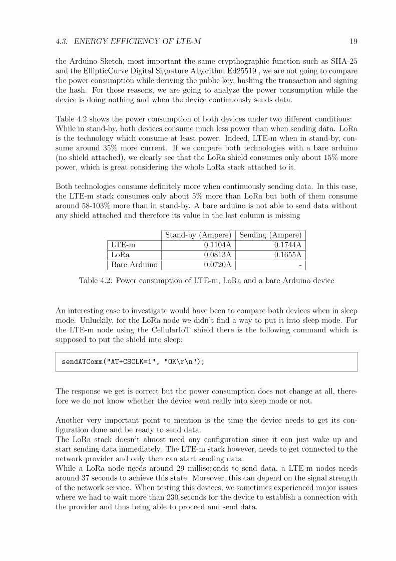
the Arduino Sketch, most important the same crypthographic function such as SHA-25and the EllipticCurve Digital Signature Algorithm Ed25519 , we are not going to comparethe power consumption while deriving the public key, hashing the transaction and signingthe hash. For those reasons, we are going to analyze the power consumption while thedevice is doing nothing and when the device continuously sends data.
Table 4.2 shows the power consumption of both devices under two different conditions:While in stand-by, both devices consume much less power than when sending data. LoRais the technology which consume at least power. Indeed, LTE-m when in stand-by, con-sume around 35% more current. If we compare both technologies with a bare arduino(no shield attached), we clearly see that the LoRa shield consumes only about 15% morepower, which is great considering the whole LoRa stack attached to it.
Both technologies consume definitely more when continuously sending data. In this case,the LTE-m stack consumes only about 5% more than LoRa but both of them consumearound 58-103% more than in stand-by. A bare arduino is not able to send data withoutany shield attached and therefore its value in the last column is missing
Stand-by (Ampere) Sending (Ampere)LTE-m 0.1104A 0.1744ALoRa 0.0813A 0.1655ABare Arduino 0.0720A -
Table 4.2: Power consumption of LTE-m, LoRa and a bare Arduino device
An interesting case to investigate would have been to compare both devices when in sleepmode. Unluckily, for the LoRa node we didn’t find a way to put it into sleep mode. Forthe LTE-m node using the CellularIoT shield there is the following command which issupposed to put the shield into sleep:
sendATComm("AT+CSCLK=1", "OK\r\n");
The response we get is correct but the power consumption does not change at all, there-fore we do not know whether the device went really into sleep mode or not.
Another very important point to mention is the time the device needs to get its con-figuration done and be ready to send data.The LoRa stack doesn’t almost need any configuration since it can just wake up andstart sending data immediately. The LTE-m stack however, needs to get connected to thenetwork provider and only then can start sending data.While a LoRa node needs around 29 milliseconds to send data, a LTE-m nodes needsaround 37 seconds to achieve this state. Moreover, this can depend on the signal strengthof the network service. When testing this devices, we sometimes experienced major issueswhere we had to wait more than 230 seconds for the device to establish a connection withthe provider and thus being able to proceed and send data.

20 CHAPTER 4. EVALUATION
Average elapsed timeLTE-m 37584msLoRa 29ms
Table 4.3: Elapsed time before being able to send data

Chapter 5
Summary and Conclusions
The main objective of this study was to compare the overhead and energy consumption ofLTE-m IoT nodes with respect to LoRa nodes. We were not able to compare the deviceswhen in sleep mode but we were able to get some results when in stand-by and whentransmitting data over to the blockchain.We can actually conclude that the LoRa protocol works best in terms of energy consump-tion. Since the nodes are not supposed to constantly transmit data and thus their mainstate will be the stand-by mode, the LoRa node considerably consumes less power. Asalready stated, both devices consume the same amount while signing transactions andsince the field/data to be signed can be the same, no difference is present there.
The transmission pattern looks quite different and so does the data overhead. WithLTE-m nodes we always send the whole IoT transaction and thus the overhead is alreadypresent there. Moreover, since the official library for the CellularIoT shield is not workingas expected, we have to introduced even more overhead as explained in a previous chapter.
Connecting the devices to the Bazo Blockchain was quite simple once we managed tocorrectly send data out of the LTE-m node. The changes we had to do for the BazoClient are minor changes compared to the rest of the study and compared to the workdone in [9].
To conclude, we can state that the overall architecture for both families of IoT devices(LoRa and LTE-m) works quite good together. LTE-m nodes can be used in scenarioswhere more data is needed in the same time window since we do not have any duty cycleor air time limits. LoRa nodes can be employed where data frequency is quite low andenergy efficiency plays a significant role.
21

22 CHAPTER 5. SUMMARY AND CONCLUSIONS

Bibliography
[1] Arduino-Lmic library, https://github.com/matthijskooijman/arduino-lmic,accessed January 2019
[2] Ed25519 Library for Arduino, https://rweather.github.io/arduinolibs/
classEd25519.htm, accessed February 2019
[3] Samwel, Batina, Bertoni, Breaking Ed25519 in WolfSSL, https://eprint.iacr.
org/2017/985.pdf, accessed March 2019
[4] Definition of a structure in Arduino, http://playground.arduino.cc/code/
struct, accessed March 2019
[5] Arduino Mega 2560, https://store.arduino.cc/mega-2560-r3, accessed August2019
[6] Sixfab Arduino CellularIoT Shield, https://sixfab.com/product/
arduino-cellular-iot-application-shield/, accessed August 2019
[7] Quectel BG96, https://www.quectel.com/product/bg96.htm, accessed August2019
[8] Explanation of double-spending attack, https://en.wikipedia.org/wiki/
Double-spending, accessed August 2019
[9] Cepilov Ile, ”Design and Implementation of an IoT-based Hierarchical Payment Sys-tem with BAZO Blockchain”, April 11th, 2019.
[10] Bazo Blockchain github repository, https://github.com/bazo-blockchain,
accessedAugust2019
[11] Sixfab Arduino Cellular IoT library, https://github.com/sixfab/Sixfab_
Arduino_CellularIoT_App_Shield,accessedAugust2019
23

24 BIBLIOGRAPHY

Abbreviations
Ack AcknowledgementAPI Application Programming InterfaceBC BlockchainECDSA Elliptic Curve Digital Signature AlgorithmEd25519 Edwards-Curve Digital Signature AlgorithmIoT Internet of ThingsHTTP Hypertext Transfer ProtocolIP Internet ProtocolJSON JavaScript Object NotationLoRa Long RangeLoRaWAN Long Range Wide Area NetworkNPM Node Package ManagerPoS Proof-of-stakeREST Representational State TransferTTN TheThingsNetworktx TransactiontxCnt Transaction CountertxFee Transaction Fee
25

26 ABBREVIATONS

List of Figures
3.1 Agnostic IoT architecture adapted from [9] . . . . . . . . . . . . . . . . . . 6
3.2 LTE-m HW Wallet for a full IoT Transaction . . . . . . . . . . . . . . . . 7
27
28 LIST OF FIGURES

List of Tables
4.1 Comparisong of converted data with the Arduino LTE-m CellularIoT Shield 18
4.2 Power consumption of LTE-m, LoRa and a bare Arduino device . . . . . . 19
4.3 Elapsed time before being able to send data . . . . . . . . . . . . . . . . . 20
29

30 LIST OF TABLES

Listings
3.1 Constant for Sixfab Cellular IoT library . . . . . . . . . . . . . . . . . . . 83.2 Private value for Sixfab Cellular IoT library . . . . . . . . . . . . . . . . . 83.3 Send data UDP function in the Sixfab CellularIoT library . . . . . . . . . 83.4 Send data command in Sixfab CellularIoT library . . . . . . . . . . . . . . 93.5 Avoid an infinite while loop in the Sixfab CellularIoT library . . . . . . . . 103.6 Reconstruct the received data with 0’s . . . . . . . . . . . . . . . . . . . . 103.7 Transaction conversion . . . . . . . . . . . . . . . . . . . . . . . . . . . . . 113.8 Gray coding forbidden characters . . . . . . . . . . . . . . . . . . . . . . . 123.9 Implementation of the UDP listener client/UDP/UDP.go . . . . . . . . . . 133.10 Conversion method for reconstructing the original IoT transaction . . . . . 14
31

32 LISTINGS

Appendix A
Installation Guidelines
A.1 Prerequisites
In order to follow this guidelines, some prerequisites are necessary. First of all, an accountwith enough funds has to be already created in the Bazo blockchain. The private andpublic key of this account have to be saved so that they can be manually inserted into theArduino sketch. Moreover, since we are going to send data through the UDP protocol,the corresponding port, in our case the port 5000, has to be opened on the router in casethat the Bazo client does not have a public IP address. For more information on how toopen the port on your router please visit: https://portforward.com/Lastly, a subscription to a mobile internet provider and an active Subscriber IdentificationModule (SIM) card is required in order to be able to send data from the LTE-m node.
A.2 LTE-m Arduino sketch
In order to run the sketch on an arduino, an Arduino CellularIoT Shield has to be con-nected to the board. The Arduino application on the computer is required as well toupload the sketch to the board. The sketch is contained in the same git repository as forthe TTN-plugin used for the LoRa project [9], in order to get it either download the repoas a zip file or open a terminal and write:
git clone https://github.com/ilecipi/TTN-plugin.git
Next, navigate into the root folder of the project, Switch to the current and most updatedbranch by typing:
git checkout ”udp”
33

34 APPENDIX A. INSTALLATION GUIDELINES
Then navigate in the folder arduino and there you will find the file lte-shield.ino.Open the file using the official Arduino Ide and insert your previously saved public andprivate key. In order to convert it to the appropriate format, you can navigate to thefollowing link and convert them:
https://cryptii.com/pipes/base64-to-hex
Make sure to install all the required libraries, including the Sixfab Arduino CellularIoTShield library, which can be found here [6]. At this point you are ready to upload thesketch using an USB cable connected to the arduino. Once uploaded, there is no requiredstep for the LTE-m Node. Just make sure that the node has internet connectivity.
A.3 Bazo Miner
The installation of the Bazo Miner stays the same like in the work done in [9]:
Getting the correct version of the miner is a little bit tricky since it hasn’t been mergedinto the official repository.First, make sure to install the latest version of GO in the RPi. Then you can downloadthe Bazo Miner by typing in the terminal:
go get github.com/ilecipi/bazo-miner
The Miner is still connected to the official repository, you have to change the remote linkof the git repository. Type in the terminal:
git remote set-url origin https://github.com/ilecipi/bazo-miner
Now you can download the required version by typing:
git pull

A.4. BAZO CLIENT 35
Switch to the current and most updated branch by typing:
git checkout ”ed25519”
Now, build the project and let the miner run with:
./bazo-miner start –database StoreA.db –address localhost:8000 –bootstrap local-host:8000 –wallet WalletA.txt –commitment CommitmentA.txt –multisig WalletA.txt–rootwallet WalletA.txt –rootcommitment CommitmentA.txt
At this point, remember to copy the file "WalletA.txt" and insert it into the root folderof the TTN-plugin.
A.4 Bazo Client
In order to run the client, the same steps of the miner have to be followed. Start bydownloading the project:
go get github.com/ilecipi/bazo-client
Move inside the project’s folder and change the url of the git repo by typing in theterminal:
git remote set-url origin https://github.com/ilecipi/bazo-client
Download the right version:
git pull
Change the branch:
git checkout ”lte final”

36 APPENDIX A. INSTALLATION GUIDELINES
Build the project and start the REST interface, which will also start the UDP listener.First make sure to have a local bazo-miner running and most important make sure to havecorrectly done the port-forwarding so that your Bazo client is reachable from outside, i.e.from your LTE-m node:
./bazo-client rest
The result should be the following: