performance evaluation of hyperthermia equipment - The American
47
PERFORMANCE EVALUATION OF HYPERTHERMIA EQUIPMENT Published for the American Association of Physicists in Medicine by the American institute of Physics
Transcript of performance evaluation of hyperthermia equipment - The American

PERFORMANCE EVALUATIONOF
HYPERTHERMIA EQUIPMENT
Published for theAmerican Association of Physicists in Medicine
by the American institute of Physics

AAPM REPORT NO. 26
PERFORMANCE EVALUATION OFHYPERTHERMIA EQUIPMENT †
REPORT OFTASK GROUP NO. 1
HYPERTHERMIA COMMITTEE*
AAPM
Members
Geoffrey S. lbbott (Chairman)Ivan Brezovich
Peter FessendenYakov PipmanTaljit Sandhu
V. SathiaseelanPaul Stauffer
Adrianne Galdi (FDA liaison)Tillman Saylor (Consultant)
“Thaddeus V. Samulski was Chairman of the AAPM HyperthermiaCommittee at the completion of this Report. Bhudatt R. Paliwal wasChairman at the formation of the Task Group and during the prepara-tion of the Report.
June 1989
Published for theAmerican Association of Physicists in Medicine
by the American Institute of Physics
‘AAPM Report No. 27 covers hyperthermia treatment planning.

DISCLAIMER: This publication is based on sources andinformation believed to be reliable, but the AAPM and theeditors disclaim any warranty or liability based on or relat-ing to the contents of this publication.
The AAPM does not endorse any products, manufac-turers, or suppliers. Nothing in this publication should beinterpreted as implying such endorsement.
Further copies of this report may be obtained from
Executive OfficerAmerican Association of Physicists in Medicine
335 E. 45 StreetNewYork,NY 10017
Library of Congress Catalog Card Number: 89-045906International Standard Book Number: 0-88318-636-5International Standard Serial Number: 0271-7344
Copyright © 1989 by the American Associationof Physicists in Medicine
All rights reserved. No part of this publication may be re-produced, stored in a retrieval system, or transmitted inany form or by any means (electronic, mechanical, photo-copying, recording, or otherwise) without the prior writ-ten permission of the publisher.
Published by the American Institute of Physics, Inc.335 East 45 Street, New York, NY 10017
Printed in the United States of America

CONTENTS
I RATIONALEII INTRODUCTIONIII PERFORMANCE EVALUATION PROCEDURES
A Visual InspectionB. Thermometry Equipment
1. Calibration Procedure2. Sources and Magnitude of Measurement
ErrorC. Generators and Power Measurement Devices
1. RF Generator2. RF Power Meter
D. Data Acquisition and Monitoring Systems1. Evaluation Procedure2. Recommended Accuracy
E. Applicators1. External Radiative Electromagnetic
Devicesa. Single Applicators
i. Phantom for SAR Measurementsii. Recommended Measurements
b. Multiple Applicator Arrays forSuperficial Heatingi. Phantomii. Recommended Measurements
C. Multiple Applicator Arrays for DeepHeatingi. Equipment
(1) Phantom(2) Electric Field Probes(3) Temperature Probes
ii. Performance EvaluationProcedures(1) E Field Probe Calibration(2) SAR Measurements(3) Leakage Measurements
2. External RF Applicatorsa. Magnetic Induction Systems
i. RF Generator and RF Power Meterii. Inductive Applicatorsiii. System Performance Evaluation
b. Capacitive Heating Systemsc. Temperature Control System (TCS)
3. Interstitial and IntracavitaryElectromagnetic Applicatorsa. Interstitial Microwave Antennas
i. System Considerationsii. Antenna Considerations
3

b. Interstitial RF (Localized CurrentField)i. System Considerationsii. Hardware Considerations
c. Interstitial Ferromagnetic Seeds4. External Ultrasound Heating Systems
a. Generatori. Frequencyii. Electrical Power
b. Single-Transducer Systemsi. Acoustical Powerii. SAR Measurementsiii. Water Coupling Systemiv. Reproducibility
c. Multiple Transducer Systems, andScanning Systems
F. Control SystemsG. Electrical and Radiation Safety
1. Electrical Leakage Currents2. Electromagnetic Radiation
IV. Frequency of Equipment Evaluation

I.RATIONALE
For hyperthermia to reach the status of an acceptedmodality,41
unequivocal proof that it is effective must be ob-tained. A clear, causal relationship must be demonstratedbetween the application of the modality and the response ofthe disease. A thorough understanding of the equipment isrequired to demonstrate such a relationship. Further, tomaximize the possibility that patients treated with theequipment receive the desired effect, the equipment shouldconform to certain minimum standards. Equipment for hyper-thermia should heat human tissue in a controlled, safe, andreproducible fashion. All ancillary equipment should oper-ate as intended, without serious risk of failure or injuryto the patient or operator. Several parameters which indi-cate the effect of the treatment should be monitored withsuitable accuracy.
This document has been prepared as a guide to assess-ing the performance of hyperthermia equipment. The proce-dures described are felt to constitute the minimum necessaryfor adequate evaluation of each piece of equipment. Theserecommendations may be utilized for developing purchasespecifications; should be considered for acceptance testingof new equipment; and should be incorporated into a qualityassurance program. Performance criteria expressed here areconsidered the minimum acceptable for a clinical system.
As is true of many newly-introduced modalities, hyper-thermia equipment and procedures undergo frequent modifica-tion. Revisions of this document will be prepared when nec-essary.
II.INTRODUCTION
Most clinical hyperthermia systems operate by causinga target volume of tissue to be exposed to electromagnetic(EM) fields or ultrasound (US) radiation. The EM or USpower is supplied by a generator and delivered to the pa-tient through an applicator. A diagram of the fundamentalcomponents of a hyperthermia system is shown in Figure 1.Applicators in use today consist of implantable or externalelectrodes, antennas, waveguides, and transducers. Thesedevices may deposit energy to only a small volume of tissuedirectly adjacent to the heating device, or they may be in-tended to deliver regional or whole-body hyperthermia.
5

6

The clinical outcome of hyperthermia depends criti-cally on the tissue temperatures obtained during the proce-dure.42,43,45,46,50,53 It is therefore important to have accu-rate information concerning the temperature throughout thetreated region of the patient. Although non-invasive ther-mometry which could yield complete 3-dimensional temperatureinformation would be most desirable, such equipment is notpresently available. In the absence of such an ideal ther-mometer, clinicians use small implanted probes, and in somecases move the probes within implanted catheters to obtainone-dimensional temperature profiles. 2 2 To minimize theneed for mechanical mapping, probes having multiple tempera-ture sensors distributed along their length often are used.
Clinical experience has shown that only a relativelysmall number of temperature probes can be inserted into apatient. Consequently, the information concerning tempera-ture distributions within the treated region will be incom-plete. The problem is especially pronounced in situationswhere large temperature gradients are encountered: tissuetemperature variations exceeding l°C per mm have been ob-served. 42 Thus, the clinician has no assurance that thetemperature throughout the tumor will be represented ade-quately by that measured at a few points.
The temperature distribution obtained during hyper-thermia treatment is influenced by the power deposition pat-tern and by the thermal and physiological properties of thetissue under treatment. The tissue properties vary from oneanatomical site to another and from patient to patient. Theidealized power deposition pattern can be characterized inthe laboratory using a phantom model which is tissue-equiva-lent at the frequency of EM or US radiation being used.Power deposition is quantified in Watts/ kg, and is de-scribed as the Specific Absorption Rate (SAR). 23 To assureproper performance of an applicator, the SAR pattern shouldbe evaluated under controlled laboratory conditions not onlyprior to its first clinical use but also at regular inter-vals as part of a clinical quality assurance program. Dur-ing routine use, a deterioration of applicator performancecould be indicated by a sudden change in the power requiredto achieve the desired temperature. The operator should becontinually on the alert for such changes.
The temperature to which the tissue is raised dependsupon, among other things, the amount of EM or US power ab-sorbed by the tissue. This quantity is determined by thepower supplied by the generator, and adjustment of the gen-
7

erator is most often the method by which tissue temperaturesare controlled.
A variety of physiological changes, including bloodflow and pH, have been reported following hyperthermia.54
In addition, many investigators have observed that their pa-tients appear to change in some physiological manner duringthe course of treatment, so that the amount of power re-quired at one heating session may be different from thelevel required at previous or succeeding sessions. Thevariation from one day to the next may be an indication of aresponse to the therapy, and may therefore be an importantquantity to document. Documentation might be achievedthrough the relationship between desired temperature and thepower required to reach that temperature. Consequently, areasonably accurate indication of the power delivered duringthe treatment is required.
Some of the procedures described here are necessarilycomplex, and require the use and understanding of sophisti-cated equipment. It is therefore recommended that the pro-cedures be performed or supervised by an individual withtraining and experience in clinical hyperthermia physics andengineering. A minimal background might consist of academicand practical training in medical physics or clinical engi-neering, followed by attendance at a formal course in hyper-thermia physics. As with other forms of medical treatment,a dedication to the task is mandatory.
An exhaustive analysis of a hyperthermia system mayexceed the capabilities of most clinical departments. Manu-facturers of hyperthermia equipment should provide rep-resentative data describing the performance of their equip-ment, and recommended operating parameters. Suitable phan-toms should be included with each system. The user of theequipment is encouraged to follow the procedures outlinedbelow to verify compliance of the equipment with the manu-facturer's specifications.
III.PERFORMANCE EVALUATION PROCEDURES
A. Visual Inspection
Some important characteristics of operation may be de-termined from a visual inspection of the system. Devicessuch as indicator lamps, digital displays, and meters shouldbe energized to ensure that they are functional. Electricalcables should be inspected for wear or breakage, and for ex-posed terminals. Loose connections should be tightened. Im-plantable antennas which exhibit bends, fraying or other
8

damage that could affect performance should be discarded.Other devices which come in contact with the patient shouldbe inspected to verify the integrity of insulation and pro-tective coatings, and the absence of abrasive surfaces.Temperature probes should be examined for bends, breaks, ordamage to connectors or insulation, and for the exact loca-tion of the temperature sensor(s). With opaque probes, mov-ing the probe across a steep thermal gradient may be re-quired to locate the position of the sensor.
B. Thermometry Equipment
The choice of a particular thermometry system shouldbe made following careful consideration of its intended ap-plication. Any measuring instrument can be considered ac-ceptable for a given purpose if the error contributed by theinstrument is small compared to other errors or uncer-tainties in the measurement. Hence, in local hyperthermiawhere large temperature fluctuations are encountered, an ex-tremely accurate thermometer may not be required. An over-all error not exceeding 0.3°C is probably acceptable, butachieving this accuracy in a clinical environment may re-quire that the thermometer agree with an institution's stan-dard to within 0.1 or 0.2%. In whole body hyperthermia, onthe other hand, where temperatures are only a few tenths ofone degree below the lethal limit and homogeneity is excel-lent, instrument errors of more than +/-0.05% may be unac-ceptable.
1. Calibration Procedure
The accuracy of the thermometry system should beverified by comparing its readings to a thermometerhaving its calibration traceable to the National Bu-reau of Standards (NBS). A high-quality mercury-in-glass thermometer with a precision of 0.05°C makes apractical, reliable and affordable standard. Thisstandard should be calibrated to the NBS standard attwo or more points within the treatment range, e.g. at41°C and at 45°C. To carry out the comparison, thetemperature probe should be affixed to the standard,so that the sensing element is close to the mercurybulb. The thermometers should be inserted into a wa-ter bath to the proper immersion depth of the mercurystandard and the readings of the two thermometers com-pared, To minimize inaccuracies caused by temperaturegradients, the water should be stirred vigorously orcirculated in a thermally insulated container. Atleast three comparisons should be done, spanning the
9

temperature range for which the thermometry system isto be used.
Thermometry systems having their own calibrationwells should also be checked for accuracy. A recom-mended procedure involves calibrating the thermometrysystem by use of its own well. Thereafter, the accu-racy of the system should be checked with an NBStraceable standard as outlined above.
In each case, the accuracy of the thermometrysystem should lie within the limits specified by themanufacturer. Deviations from the specified accuracymay indicate that the equipment is unreliable andshould be returned to the manufacturer for repair.
2. Sources and Magnitude of Measurement Error
Temperature measurements in hyperthermia are es-pecially susceptible to errors since such measurementsare often taken in the presence of strong electromag-netic or ultrasound fields.27,36 In the following, themajor sources of error will be explained and methodsfor dealing with the ensuing problems will be sug-gested.
First, electromagnetic (EM) fields within thetreatment room may interfere directly with the sensi-tive electronics of the readout unit which convertsthe signals from the temperature sensors to tempera-ture readings. 7,8,10,11,25 One must keep in mind thatsuch signals are very weak; a typical thermocoupleprobe generates only 40 uV/°C. Temperature probeswith metallic leads as well as AC power cords can actas effective antennas for picking up FM energy andtransmitting it to the readout unit. Such direct in-terference can be reduced substantially by propershielding of the readout unit and by careful filteringof all incoming signal and power lines.7,29 A goodthermometer for hyperthermia should incorporate suchfeatures.
The presence of direct electromagnetic interfer-ence can be detected readily by a sudden change in thetemperature reading when the hyperthermia apparatus isturned on.8,16 When the apparatus is turned off, thereading should change in the opposite direction anequal amount.(see Figure 2a) The error due to directelectromagnetic interference can be positive or nega-tive, i.e., the thermometer may read higher or lower
10

IndicatedTemperature
Time
Figure 2a: An example of the effect of direct electromagnetic interferenceon the indicated temperature
IndicatedTemperature
Time
Figure 2b: Typical response of a temperature probe exhibitingelectromagnetic interference or probe heating.
11

than it did before the hyperthermia apparatus wasturned on. A direct interference error can also beidentified by its strong dependence on the spatial re-lation between the thermometer and the hyperthermiaequipment. If the electromagnetic interference islarge, especially if it drives the thermometer readingout of range, frequent calibrations will be requiredto establish that the instrument can tolerate suchstrong interference without damage.
A second error can arise during hyperthermia ifthe temperature probe (or the catheter) absorbs energymore rapidly than the surrounding tissues. In thiscase the sensor will become hotter than the body tis-sues and the measurement, although showing the correctsensor temperature, will be higher than the unper-turbed tissue temperature. 8,16 Plastic encased temper-ature probes, for example, are particularly suscepti-ble to this t e of error when used in USfields 7,20,3O,33,35 Because of the high rate of US en-ergy absorption by most plastics, the casing willoverheat and transmit the high temperature to thesensing element.
A third type of error can arise if the tempera-ture probe perturbs the US or electromagnetic fieldand thereby alters the tissue temperature. 9,10,14 Atypical example for this problem is the tissue heatingaround a thermocouple in microwave or RF hyperthermia.At high frequencies capacitive RF currents can be in-duced in the thermocouple wire. The ensuing concen-tration of RF current flow in the immediate vicinityof the thermocouple will lead to a corresponding in-crease in tissue temperature. While the indicatedreadings will represent correct tissue temperatures,the highly localized hot spots will be poor indicatorsof the prevailing temperature within the tumor.
The presence of the latter two error sources canbe detected by an initially rapid rise of the indi-cated temperature occurring immediately after the hy-perthermia apparatus has been turned on (Figure 2b).After the equipment has been turned off, a similarrapid drop in the temperature indication will occur,often with a decay time of a few seconds. If such er-rors are found to be present, all temperature readingsduring clinical hyperthermia should be taken while theheating power has been interrupted briefly.20,29 How-ever, a small error will always remain since it will
12

be difficult to distinguish precisely between the"tail" of the initial rapid temperature drop and themore gradual normal cooling of the tissues. Extrapo-lation to the correct tissue temperature at the timeof power off is therefore inaccurate. If this suddenchange exceeds one or two degrees C, temperature mea-surements will become unreliable and a better suitedthermometer should be used.
thermal conductivity of temperature probes, especially Another source of error is introduced by the
metallic probes. The result is poor spatial accuracyand is especially noticeable in regions of high ther-mal gradient.8,15,35
Finally, mechanical distortion of temperatureprobes can affect the measurement. Specifically,bending some fiber-optic probes can introduce error.
Note: Because the accuracy of temperature mea-surements depends not only on the thermometer but alsoon the hyperthermia equipment and its configuration,the performance of a thermometry system should alwaysbe evaluated in conjunction with the hyperthermia ap-paratus to be used later for patient treatments. Oneshould carry out the evaluation under simulated clini-cal conditions which might be expected to produce max-imum measurement error.
c. Generators and Power Measurement Devices
1. RF Generator
The RF generator must be capable of producingthe full output power specified by the manufacturer atall intended operating frequencies. Output powershould be controllable from virtually zero to maximumin a smooth or stepwise fashion. The generator shouldbe connected through an appropriate power meter to amatched load (typically 50 ohms) for all tests (seeFigure 3). The operating frequency should be checkedwith a digital frequency counter or an oscilloscope.
For a generator to be suitable for clinical hy-perthermia it must be capable of tolerating someimpedance mismatch. If the manufacturer specifies thegenerator to be immune to any impedance mismatch, oneshould test this capability by connecting the outputto an in-line power meter. When the output side ofthe power meter is left unconnected, an infinite load
13
14
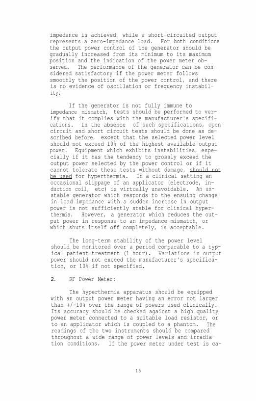
impedance is achieved, while a short-circuited outputrepresents a zero-impedance load. For both conditionsthe output power control of the generator should begradually increased from its minimum to its maximumposition and the indication of the power meter ob-served. The performance of the generator can be con-sidered satisfactory if the power meter followssmoothly the position of the power control, and thereis no evidence of oscillation or frequency instabil-ity.
If the generator is not fully immune toimpedance mismatch, tests should be performed to ver-ify that it complies with the manufacturer's specifi-cations. In the absence of such specifications, opencircuit and short circuit tests should be done as de-scribed before, except that the selected power levelshould not exceed 10% of the highest available outputpower. Equipment which exhibits instabilities, espe-cially if it has the tendency to grossly exceed theoutput power selected by the power control or if itcannot tolerate these tests without damage, should notbe used for hyperthermia. In a clinical setting anoccasional slippage of an applicator (electrode, in-duction coil, etc) is virtually unavoidable. An un-stable generator which responds to the ensuing changein load impedance with a sudden increase in outputpower is not sufficiently stable for clinical hyper-thermia. However, a generator which reduces the out-put power in response to an impedance mismatch, orwhich shuts itself off completely, is acceptable.
The long-term stability of the power levelshould be monitored over a period comparable to a typ-ical patient treatment (1 hour). Variations in outputpower should not exceed the manufacturer's specifica-tion, or 10% if not specified.
2. RF Power Meter:
The hyperthermia apparatus should be equippedwith an output power meter having an error not largerthan +/-10% over the range of powers used clinically.Its accuracy should be checked against a high qualitypower meter connected to a suitable load resistor, orto an applicator which is coupled to a phantom. Thereadings of the two instruments should be comparedthroughout a wide range of power levels and irradia-tion conditions. If the power meter under test is ca-
15

pable of measuring forward power, reflected power, andload power, each one of these scales should be com-pared to the standard meter.
D. Data Acquisition and Monitoring Systems
1. Evaluation Procedure
If possible, determine the accuracy of the de-vice to be monitored. (See previous sections) Thismay not be practical if the device (for example, athermometer) is an integral part of a system which in-corporates monitoring capabilities. However, individ-ual analysis of each component of a system assures themost dependable operation. Follow the recommendationsin the appropriate section of this protocol.
Repeat several of the measurements suggested forthe component to be monitored using the data acquisi-tion system to measure and record the data. Select arange over which to test the device, which approxi-mates clinical conditions.
Compare the various sets of data to determinethe precision of the monitoring and recording devices.
2. Recommended Accuracy
Equipment used for monitoring and recording inhyperthermia systems is generally standard and conven-tional. The techniques used for transferring the dataare likewise straightforward and uncomplicated. Con-sequently, no concession to accuracy need be toler-ated, as might be the case for the measuring equipmentitself. Monitoring and recording equipment should beaccurate to within +/-1 percent of full scale for ana-log devices, and to within +/- one digit for digitalequipment.
The frequency of data acquisition should be de-termined before the instrument is placed into clinicalservice. Sampling rates of less than one reading (ofeach parameter) every 10 seconds may be inadequate forclinical use.
The accuracy of calculation algorithms for ther-mal "dose"21,49 is not easily specified. It is recom-mended that the user of such an algorithm compare itsperformance against the manufacturer's description ofits operation. Discrepancies should be reported to
16

the manufacturer, and use of the capability should besuspended or moderated until the discrepancy is re-solved. At this time, calculation procedures do nothave widespread acceptance and must be used with cau-tion.
E. Applicators
1. External Radiative Electromagnetic Devices
a. Single Applicators
The most practical method for the evaluation ofSAR patterns of external applicators is based on themeasurement of temperature rise during a short inter-val of time. The SAR is defined as the power absorbedper unit mass23, and is computed as
where
c = specific heat of the tissue or phantom mate-rial in J/kg°C (a typical value for muscle phantom is3500 J/kg°C), and
dT = temperature rise (degrees C) during timeinterval dt (seconds). Ideally, the temperature riseand time interval would be true differentials. Inpractice, dT/dt is approximated by ∆ Τ/∆ t where thetime interval is sufficiently short that conductioneffects are negligible and the temperature rise ∆ T isproportional to the time interval At.
dT can be measured either using a temperatureprobe or a thermographic camera. 13(Figure 4) Thethermographic camera technique has the advantage thatthe SAR pattern is obtained in a plane rather than ata point as in a single measurement trial. This, how-ever, is accomplished at the expense of accuracy inthe measurement of temperature rise in comparison withthe use of a temperature probe such as a thermister.32
Regardless of the method used, one should be awarethat SAR measurements often involve large uncertain-ties. The measurements should be repeated severaltimes, and an average value determined.
Special precautions should be taken in the mea-surement of temperature rise when temperature probes
17

18

such as thermisters or thermocouples are used. Non-perturbing and interference-free probes such as highresistance thermisters or fiber-optic sensors are pre-ferred. If ordinary thermisters or thermocouples areused the accuracy of the temperature measurement inthe microwave field should be established before SARmeasurements are made. (Section III.B.2.)
The temperature rise data to be used for SARcalculations should be taken from the linear portionof the temperature vs time plot (Figure 5). It isrecommended that high power for short intervals (lessthan 30 seconds) be employed for this purpose. Thisis necessary to minimize effects due to thermalconduction. If the temperature at the measurementpoint is changing prior to power-on, one can correctfor this as described by Roemer et al.48
i. Phantom for SAR Measurements
For performance evaluation of most mi-crowave external applicators, a phantom consist-ing of layers of fat- and muscle-equivalent ma-terial can be used. For example, a 30 cm x 30cm x 15 cm (depth) plexiglass container filledwith muscle-equivalent material, with a 1 cmthick overlying layer of fat-equivalent materialis sufficient. Procedures for preparing musclephantoms have been described by Chou 12 andHartsgrove 26 for a wide range of microwave fre-quencies. The fat layer is optional and may bedeleted. However, it should be understood thatthe fat layer may affect the coupling effi-ciency.
ii. Recommended Measurements:
(1). Although a complete three-dimensional mapof SAR is preferred, this may not be practicalfor many users. For routine measurements, atleast three profiles should be obtained: Thecentral depth profile, and two orthogonal pro-files at 1 cm depth in muscle in a plane perpen-dicular to the depth profile. These lateralprofiles should extend several cm beyond the ap-plicator boundaries, to indicate whether hotspots exist outside the aperture.
19

20

(2). Some applicators are designed to be oper-ated at several different frequencies or over afrequency range. The above measurements shouldbe repeated at the intended frequencies (or rep-resentative frequencies) to cover the range ofuse. This is important since the SAR pattern ofa particular applicator is likely to change withthe frequency of the applied power.
(3). The user should be aware that the attach-ment of a coupling bolus can have a large influ-ence on the power deposition pattern. Theprocedures described here should be conductedfor arrangements which mimic the anticipatedclinical use of the equipment.
(4). The absolute value of the SAR per unit netinput power should be measured at a fixed depth(1 cm) in muscle phantom on the central axis ofthe applicator. Note that, particularly in thecase of ultrasound hyperthermia, the appropriatereference depth may vary with the applicator andoperating conditions, and should be selectedcarefully. This value should be monitored atperiodic intervals (Section IV) to assure sta-ble, reproducible performance.
(5). Prior to using the applicator for thefirst time, and whenever new treatment configu-rations are contemplated, leakage radiationshould be measured using an isotropic probe,calibrated near the frequency of use.4,38 Thiscan be done initially with the same set-up andpower levels used for SAR measurements as de-scribed above. Measurements of leakage radia-tion should be made during treatments, to assureoperator and patient safety. Measurements ofpower density (mW/cm2) should be made in theaperture plane at a lateral distance of 5 cmfrom the applicator walls. Recommended limitsof leakage radiation are described in SectionG 3,38
b. Multiple Applicator Arrays for SuperficialHeating
Radiating-element applicators are sometimes ar-ranged in planar arrays for superficial tissue heat-
21

ing. The total SAR pattern, however, is generally nota superposition of the SAR patterns of individual ele-ments. Instead, the array must be evaluated as an in-tact unit.
i. PhantomThe phantom to be used is again a planar
model as described above (III.E.l.a.).
ii. Recommended Measurements:
(refer to Section III.E.l.a.)
(1) For a multiple-element planar array appli-cator, the lateral SAR profiles should be chosenso that the space between radiating elements iscovered. For example, when evaluating a rectan-gular arrangement of radiating elements (Figure6a), the recommended lateral profiles are AA'BB', CC' and DD' at 1 cm depth in muscle-equiva-lent material.
Similarly, a minimum of two depth profilesshould be obtained (Figure 6b).
(2) The dependence of the SAR distribution onoperating frequency can be evaluated as de-scribed in section III.E.l.a. above for singleapplicators.
(3) A measurement of the SAR per unit net in-put power can be made as described in sectionIII.E.l.a. above for single applicators.
(4) Measurements of leakage radiation shouldbe made as suggested in section III.E.l.a.above.
C. Multiple Applicator Arrays for Deep Heating
The most basic array for external deep heatingwill likely consist of an annular ring of radiatingapertures. The parameters of interest are the exter-nal electric fields within the array at the surface ofthe patient's body, the SAR pattern within the targetvolume, and the radiation leakage levels of the scat-tered fields around the device. A performance evalua-tion kit consisting of a phantom, electric field
22

23

probes and temperature probes is recommended to studythese parameters.
i. Equipment
(1) Phantom
A standard torso phantom similar to theone developed by the Center for Devices and Radiological Health (CDRH) for quality assuranceof regional heating devices5 should be used. Byreplacing a highly variable hyperthermic systemload (the patient) with a stable load (a phan-tom) the relative heating capabilities can bedetermined under stable, repeatable conditions,with a reduced number of variables. The use ofa standard phantom will also enable intercompar-ison of "similar" devices at different sites.
(2) Electric field probes
E-field probes are useful for measuringrelative electric field strengths external tothe patient's body and internal fields within aphantom. This is necessary to assess the symme-try of the fields. A microwave diode with itsleads acting as a dipole antenna and connectedto the detecting circuitry using high resistanceleads can be used as an E-field probe. Theprobe outputs a maximum dc voltage when alignedwith the electric field. The detected voltageis directly proportional to the square of theelectric field strength at the measurementpoint.able55
These probes are commercially avail-and may be provided by the manufacturer
of the array.
(3) Temperature probes
Nonperturbing temperature probes should beused for the SAR measurements. The probesshould be small in diameter and long enough topermit measurements throughout the length of thephantom.
24

ii. Performance Evaluation Procedures
(1) E-field probe calibration
The absolute magnitude of E-field probereadings is generally less important than therelationship between the readings of severalprobes. Consequently, comparison with a stan-dard E-field instrument is not recommended here.Instead, the probes should be compared with eachother under reproducible conditions, keeping inmind that the orientation of the probe to thefield may affect the reading. The phantom de-scribed above may be used, with catheters tapedto its surface (top, bottom, and both sides) tofix the probe position. The generator should beadjusted to a relatively low power setting (e.g.200 watts), and readings made at each locationwith each probe. It may be useful to leave oneprobe fixed while the others are moved, to moni-tor the stability of the power level.
(2) SAR measurements
Before attempting SAR measurements, theoutput power level of the applicators should beadjusted for symmetric (or if desired, asymmet-ric) power deposition. The E-field probesshould be used for this adjustment. SAR mea-surements should be made in at least threeplanes; the central plane, and representativeparallel planes on either side. The SAR can bemeasured by determining the rate of temperaturerise in the tissue simulating gel during a shortexposure of RF power. The temperature probesare inserted into the catheter tracks so thatthe tips lie in the plane of interest. The rel-ative temperature rise obtained when a power ofabout 600 watts is applied for about 1 minutewill give the required SAR. This procedure canbe repeated for other planes. As discussed insection III.E.1.a., conduction effects, particu-larly in regions of steep thermal gradient, maybe significant. If the temperature vs. timeplots indicate a non linear relationship, ashorter time interval may be required.
25

(3) Leakage measurements
Antenna arrays for deep heating presentunusual leakage problems. Because it is moredifficult to couple the energy effectively intothe patient from multiple applicators, the rela-tive leakage level may be higher than for a sin-gle applicator. In addition, the overall powerapplied to the array is often quite high. Theseleakage levels may cause substantial patientheating outside the intended treatment volume,especially in regions of small diameter such asthe head and neck and extremities. 24,55 A surveyof the leakage radiation should consider theselocations, as well as locations likely to be oc-cupied by the staff. Reflections from shieldedenclosures and other equipment may cause highleakage readings at unexpected locations.
A calibrated RF radiation hazard monitor,suitable for the unit's operating frequency,should be used. An isotropic probe is prefer-able. The levels will be influenced by the typeof load in the array and the environment withinthe room and these measurements can only providea guideline. The survey should be performedwith the phantom positioned in the array. Inaddition, it will be necessary to monitor thelevels routinely during treatments.
2. External RF Applicators
a. Magnetic Induction Systems
Induction hyperthermia equipment generally con-sists of an RF power generator, an RF power meter, animpedance matching network, one or more induction coilapplicators, a set of connecting cables, and(sometimes) a patient support assembly. The impedancematching network can be a separate unit, or it can beincorporated into the applicators or the RF genera-tors. To evaluate the performance of the equipment itis recommended that the proper functioning of each ofthe major components be evaluated separately. There-after, the performance of the entire system should bechecked on a phantom, using a setup typical for theintended patient treatments. If the individual com-ponents of the apparatus are not easily accessible, athorough check of the entire system can be substituted
26

for the performance evaluation of the individual com-ponents. In that case, the system performance shouldbe tested over a broad range of anticipated treatmentsituations. These tests should include operation atall intended RF frequencies with phantoms simulatinglarge and small patients.
The need to evaluate the performance of the com-plete system is due to the fact that the interactionbetween the individual components (matching network,applicators, generator) can lead to unexpected prob-lems. For example, an RF generator may work perfectlywhen its output is connected to a shielded load. Inan actual hyperthermia treatment, however, the largeRF applicators together with the patient act as power-ful transmitting antennas. Unless the oscillator andother low power components within the RF generator areproperly shielded, a positive feedback loop can de-velop, causing the system to go into uncontrolledself-oscillations. This can cause the RF generator tobehave erratically, possibly producing its full outputpower, regardless of the setting of the output powercontrol. The frequency of such self-oscillation maybe different from the normal operating frequency ofthe hyperthermia system.
i. RF Generator and RF Power Meter
The performance of these units should beevaluated as described in section III.C.
ii. Inductive Applicators
Induction coils should be inspected visu-ally to assure that their construction complieswith the manufacturer's specifications. Consid-ering the high voltage and power levels presentin many induction coils, particular attentionshould be paid to the adequacy of the insula-tion. Although high frequency currents at thepower levels used in hyperthermia are generallynot life-threatening, they can cause painfulburns to the patient or the operator. Becauseof the strong interaction between the variouscomponents and the patients, applicators shouldbe tested as part of the system evaluation.
27

iii. System Performance Evaluation
After the hyperthermia system has beenfully assembled it should be tested on a suit-able phantom. Because inductive hyperthermiasystems generally operate in the frequency rangeof 1 MHz to 27.12 MHz, a phantom can be madeeasily from tap water by dissolving in it 4.4 gtable salt per liter. The so-formed saline so-lution can be contained in any electrically non-conducting container having suitable dimensions.The geometrical shape of the phantom should re-semble the shape of the patient region to betreated, but does not need to include areaswhere the magnetic field strength is less than10% of its maximum within the patient. For ex-ample, a 10 cm diameter surface applicator to beused for treatments at 3 cm depth or less, canbe checked by placing it against the surface ofa 15 cm cubic container of saline solution. Themagnetic field-intensity beyond the containerwill be negligible, and one can therefore expectvery little variation in the outcome of the testif the dimensions of the container are in-creased.
b. Capacitive Heating Systems
Capacitive hyperthermia equipment generally con-sists of an RF power generator, an RF power meter, animpedance matching network, a set of electrode appli-cators, a temperature control system for the applica-tors, a set of connecting cables and water coolinghoses, and a patient support assembly. To evaluatethe performance of the equipment, it is recommendedthat the proper function of each of the major compo-nents be evaluated as a system, for reasons discussedearlier. (Section III.E.2.a.).
C. Temperature Control System (TCS):
Most capacitive hyperthermia systems will beequipped with provisions for controlling the tempera-ture of the electrode applicators via circulating wa-ter. The performance of the TCS should be evaluatedwith the hyperthermia system fully assembled and theRF power adjusted to levels ranging from zero to typi-cal clinical values. It should be verified that theTCS is capable of controlling the electrode tempera-
28

ture within the full range specified by the manufac-turer. The time required to respond to changes in theselected electrode temperature should also be recordedand compared to the specifications (if available). Asurface temperature probe of reasonably high qualitycan be used to measure electrode temperatures. Goodcontact between the probe and the electrode is re-quired.
3. Interstitial and IntercavitaryElectromagnetic Applicators
a. Interstitial Microwave Antennas
1. System Considerations
Optimum tissue heating is dependent uponthe division of RF power among the antennas.The operation of the power distribution systemshould be evaluated with all outputs terminatedwith either a dummy load or an applicator and aphantom, and with the power distributed equallyamong the channels. (Refer to Section III.C forrecommended power measurement procedures.) Athrough-line power meter can be inserted betweenthe generator and antenna of the channel to betested. The measurements should be made withthe generator adjusted to 25, 50, and 100% ofits maximum power, to demonstrate linearity ofpower distribution. All outputs should betested in this way, and each should fall within10% of the mean value. Systems which exceedthis tolerance should be serviced or replaced.
All coaxial cables should be inspectedregularly for power loss, cable or connectorheating, or loose connectors. Visual inspec-tions play a major role, but measurements shouldalso be made of reflected power when the cablesare terminated with a 50 ohm load. Under theseconditions, reflected power levels exceeding 10or 20% are indicative of physical damage to thecables or connectors.
The temperature monitoring and controlsystems should be tested according to sectionIII.D.
29

ii. Antenna Considerations
As with external applicators, interstitialantennas should be matched properly to the tis-sue or phantom and the generator. Reflectedpower less than 10% of the forward power indi-cates acceptable matching.
Antennas should show comparable and con-sistent heating in a tissue-equivalent phantom.A measurement of SAR should be made at a point 5mm from the antenna axis, at the point of maxi-mum SAR. The value determined should be com-pared with the measurement made when the probewas new. A value of approximately 30 W/kg perwatt of applied power is typical of some de-signs.
The relative SAR pattern also should bemeasured, for comparison with data provided bythe manufacturer. Heating times should be keptas short as possible (30 seconds is reasonable).At a minimum, the SAR should be measured along aline parallel to the antenna, at a distance of 5mm away from the axis. The antenna should beinserted into the phantom to a depth comparableto that used for clinical treatments. The sen-sitivity of the heating pattern to the depth ofthe antenna should be investigated, as extremesurface heating may occur with incorrect depths.
b. Interstitial RF (Localized Current Field)
i. System Considerations
Begin by ensuring that the RF power is di-vided properly among all channels activated, andthat the reflected power is reasonable. A powermeter and a 50 ohm load should be used as de-scribed in part III.E.3.a.i (above). Next, in-vestigate the time sequencing or duty cycle con-trol of the channels. A visual inspection ofall indicators and switches should be performed.The accuracy and linearity of the cycle timingcan be determined by displaying the output wave-form with an oscilloscope. (A bandwidth of atleast 10 MHz is recommended.) Ensure that thereare no switching transients or current over-shoots which exceed 10% of the output amplitude.
30

The output should also be measured with bothopen and short circuit conditions. The designof the equipment should minimize the risk of de-velopment of electric current paths not intendedfor treatment. Likewise, the user should beaware of the possible electrical hazard to thepatient in the event that an electrode shouldbecome disconnected.'
Refer to Section III.G for electricalsafety measurements, and to Section III.D fortemperature monitoring and control functions.
ii. Hardware Considerations
Several visual inspection procedures canhelp assure proper operation of the hardware.All cables should be checked for physical dam-age, and connectors should be clean and tight.Reusable electrodes must be straight and sharp,and without damage to the insulation. In mostsituations, electrodes must be parallel for op-timum heating, so bent or kinked electrodesshould be discarded.
c. Interstitial Ferromagnetic Seeds
Proper heating of interstitial seeds dependsupon correct operation of the inductive heating appa-ratus. Refer to section III.E.2.a. for procedures forevaluating the heating equipment. Refer also to Sec-tion III.B for procedures for evaluating the ther-mometry system.
The thermoregulating temperature of curie-pointferromagnetic seeds may be investigated in a phantom.A suitable thermometer probe may be positioned at 5 mmradius from the midpoint of the seed. Sufficient RFpower should be applied to reach the thermoregulationmode, and maintained for a predetermined interval (atleast 10 min). The temperature reached should be con-stant to within 2%. Compare the temperature at thereference point to the original seed performance; ad-just the thermal dosimetry (ferro-seed spacing) ac-cordingly, or discard the seed. Bent seeds should bediscarded, as they may not heat properly.
31

4. External Ultrasound Heating Systems
a. Generator
RF generators for ultrasound (US) hyperthermiaoperate in the frequency range from 300 kHz to 5 MHz.Because transducer operating characteristics usuallyare extremely sensitive to generator frequency, theperformance requirements are stringent.
i. Frequency
As the character of the near field is verysensitive to frequency, the frequency of thegenerator should be known to within 1.0 kHz, andshould be stable for no less than the durationof a typical heating session (a minimum of twohours is recommended). A calibrated frequencymeter should be used. The generator frequencyshould be adjustable throughout a range whichincludes the nominal resonance frequency +/-l0%for each transducer associated with the system.The range will accommodate variations in operat-ing parameters sometimes required to reducenear-field effects.
ii. Electrical Power
Requirements for and evaluation of US gen-erators are similar to those for generators forRF heating systems, and include investigation ofelectromagnetic interference (EMI). Refer toSection III.C for recommended specifications andmeasurement procedures.
b. Single-Transducer Systems
i. Acoustical Power
The relationship between electrical powerand acoustical output for a given transducer issometimes non-linear at high power levels. Con-sequently, it is necessary to characterize eachtransducer over a range of representative powerlevels, for each nominal operating frequency.31
An US wattmeter or radiation force balanceshould be used. Next, the dependence of acous-
32

tical power on frequency should be determined.The peak acoustical power should occur at a fre-quency falling within 10% of the nominal operat-ing frequency (selected to suppress near-fieldeffects, while at the same time having ac-ceptable output power and efficiency). Duringthis test, it is advisable to operate the gener-ator at a level corresponding to an acousticalpower output of approximately 50% of the maximumachievable. Heating of the transducer elementitself is normal, and may affect the relation-ship between acoustical output and electricalinput power. This relationship should be mea-sured as a function of time of operation at highpower. If transducer heating causes a change inthe relationship of more than 5%, adjustments tothe transducer cooling system should be made.
ii. SAR Measurements
As with RF applicators, a full three-di-mensional map of the power deposition pattern isdesirable, but impractical. In practice, a mea-surement of peak SAR at a reference location iscombined with longitudinal and transverse pro-files of relative power deposition.
The SAR should be measured in a tissue-equivalent phantom 17 using bare thermocouplesfixed at a multiplicity of spatial points. Al-ternatively, this may be done by mapping tight-,fitting probes in good thermal contact with verythin-walled stainless steel needles embedded inthe phantom. This latter technique will lead tosome thermal smearing which must be assessed(section III.B.2.) If a tissue-equivalent liq-uid18,44 (or water) phantom is used, the relativepower deposition profile can be made rapidly us-ing an RTV-encapsulated thermocouple19 or aminiature hydrophone. Refer to Section III.Efor the procedure for computing SAR, and SectionIII.B.2. for cautions concerning temperaturemeasurement errors in US fields.
The transducer should be indexed to assurereproducible positioning, and lateral beam pro-files should be measured at 2 cm intervalsthroughout the heated volume. Scans should bemade with the transducer rotated to different
33

angles, to demonstrate circular symmetry of theheating pattern. The power deposition patternof focussed transducers should be mapped at highspatial resolution, ideally 2 mm in all direc-tions in the vicinity of the nominal focus.
The measurements should be repeated at allfrequencies intended for clinical operation, andat representative power levels for each trans-ducer.
iii. Water Coupling System
A water system is required for good acous-tical coupling, and circulation is necessary tocool both the transducer and the patient sur-face. The volume of water circulated must beadequate to carry out both tasks. To provideadequate control over patient surface tempera-ture, the water temperature should be regulatedto within 0.5%. The cooling water must be de-gassed well, particularly for operation at highpower. Recommended procedures for degassingare:
- boiling for 15 minutes, or- maintaining at a pressure of less than30 mm of mercury for 3 hours,
less than 12 hours before use.19,31 Inadequatedegassing may result in cavitation and greatlyreduced heating efficiency. Evidence of cavita-tion may be observed by shining a bright flash-light through the coupling water adjacent to thetransducer, when operating the system in a dark-ened room. The user will observe the presenceof minute bubbles and enhanced scattering oflight.
iv. Reproducibility
Repositioning of the applicator and repro-ducible coupling to the phantom should be as-sured by repeating a phantom set-up at leastfive times. A measurement of SAR should be madeat a reference point at both low and high power,each time the setup is repeated. The standarddeviation of the measurements should not exceed5%.
34

C. Multiple Transducer Systems, and ScanningSystems
Each transducer of a multiple transducer systemshould be characterized as described above. Becausearrays and scanning systems can vary widely, it willbe necessary to devise tests which evaluate the repro-ducibility and safety of representative clinical con-figurations.
F. Control Systems
Improper operation of the control devices installed ina hyperthermia system can lead to extremely dangerous situa-tions. It is of paramount importance that the device (orsoftware) which controls the heat-delivering equipment re-spond properly to the temperature or other parameter beingmeasured. It is difficult to analyze such a control systemin a manner which is representative of the clinical use ofthe equipment without employing an animal patient or a dy-namic phantom model.
However, it is possible to perform the simpler analy-sis recommended here. The procedures described below shouldbe conducted prior to clinical use, and at any time that theoperation of the unit is questioned. Otherwise, routineclinical operation will demonstrate that the system is func-tioning properly.
All other recommended quality-assurance proceduresshould be performed to ensure the proper operation of eachcomponent. Two water baths (or similar environments withcontrollable temperature) are required. The power-deliveryequipment (antennas, transducers, etc) should be arranged toheat a phantom unrelated to the water baths. The tempera-ture and power absorbing qualities of the phantom are notimportant for this control system verification (Figure 7).
If the control system permits regulation of the heat-delivery equipment based on the temperature of one or morethermometers, these thermometers and the target temperature(say, 43%) should be designated. Similarly, if the controlsystem terminates heating whenever a predetermined tempera-ture is exceeded, the maximum allowable temperature (say,47°C) should be designated. All thermometer probes shouldbe placed in one of the water baths adjusted to a tempera-ture several degrees below the target temperature (say,41%). The heat-delivery system should then be energized.
35

Figure 7: Arrangement for evaluating the operation of controlsystems.
36

The following test of the control system should be con-ducted:
1. Move one of the control thermometers fromthe 41°C water bath to a 44°C environment. Verifythat the power to the heat-delivery system (or portioncontrolled by the thermometer which was moved) is re-duced.
2. Replace the thermometer into the 41°C en-vironment and verify that the power to the heat-deliv-ery system is adjusted toward its original level.
Repeat these steps for each of the control thermome-ters.
The limiting capability should be tested as follows:1. Place a thermometer into a 48°C environ-
ment and verify that the power to the heat-deliverysystem is interrupted.
2. Return the thermometer to the 41°C envi-ronment, and verify that the heat-delivery system canbe energized readily.
Repeat these steps for each thermometer. Notethat a more demanding test may be conducted by chosingwater-bath temperatures which are closer to the targetand limiting temperatures.
G. Electrical and Radiation Safety
1. Electrical Leakage Currents
As with any electrical equipment to be used in apatient environment, hyperthermia equipment must bechecked routinely for electrical safety. Test proce-dures for 60 Hz electrical leakage current have beendescribed by the American National Standards Insti-tute.1 This standard recommends semi-annual in-spection of output isolation from ground at 60 Hz andat the RF source frequency. Limits are 10 uA RMSelectrode-to-ground and 100 uA RMS chassis-to-groundworst case leakage current at 60 Hz with the equipmentground Intact and Disconnected, polarity Normal or Re-versed, and the unit Off or in Standby-On mode. Nopublished standards could be found which address elec-trical leakage at frequencies above 1 MHz, althoughANSI1 suggests that the limits recommended at 100 kHzbe applied to higher frequencies. However, the Na-
37

tional Fire Protection Association recognizes the needfor further study.40 The American National StandardsInstitute limits the high frequency leakage power fromelectrosurgical devices to 4.5 watts.2 This standardmay be a suitable guideline for components of a hyper-thermia system other than the applicator.
These tests should normally be performed by theClinical or Biomedical Engineering house staff at eachfacility who are qualified to interpret the detailedlisting of test procedures, current limits, and testconditions recommended in the guidelines. Compliancewith these standards is especially important for hy-perthermia equipment with direct electrical connec-tions to the patient, such as interstitial RF elec-trodes and implanted temperature sensing devices,where the electrical safety hazard is greatest.
2. Electromagnetic Radiation
Hyperthermia treatments involving the use ofhigh-power high-frequency generators are potentiallyhazardous to both the patient and equipment operatorsdue to leakage of electromagnetic energy from the gen-eratorsbles.34,47
treatment applicators and interconnecting ca-This undesired "leakage radiation" can pro-
duce significant interference with nearby sensitiveequipment such as thermometry systems and physiologi-cal monitors. In addition to the electrical interfer-ence problem there are potential biological hazards ofnon-ionizing electromagnetic radiation, even at lowpower levels.6,28,37,38,38,39,51 Stray radiation may produceexcessive heating at sites remote from the intendedtreatment site, however. Thus, the FDA's Center forDevices and Radiological Health (CDRH) has producedthe ANSI Radiofrequency Protection Guide to establishlimits on the allowable leakage radiation around high-frequency equipment. 3,38 While the limits are fre-quency dependent, the standard recommends a maximumsix-minute averaged leakage power density of 5 mW/cm2
(measured ≤ 5 cm from any chassis or applicator sur-face) for microwave frequencies above 1.5 GHz. Evenmore stringent requirements are specified for lowerfrequencies and for longer exposure times. Thus,leakage radiation should be monitored with a cali-brated isotropic radiation survey meter during eachnew procedure to comply with the regulations and toensure safe operating conditions. 4 Special attentionshould be given to monitoring sensitive regions suchas the eyes, face or groin area. Treatment conditions
38

which produce leakage in excess of the limits shouldbe reconfigured.
IV. FREQUENCY OF EQUIPMENT EVALUATION
The following table is intended as a guide to the fre-quency at which performance evaluation procedures should berepeated.where.52,53
Similar guidelines have been published else-
Evaluation frequencies are specified for two condi-tions: For equipment that is operating normally and hasdemonstrated its reliability, a "normal minimum" frequencyof evaluation is suggested. Equipment which has not yetdemonstrated such reliability or which exhibits unstable orerratic behavior should be evaluated more often, at no lessthan the "initial recommended" frequency. In addition, theevaluation procedures should be conducted whenever damage tothe equipment is suspected, and also when a piece of equip-ment is returned to service after a hiatus exceeding the"initial recommended" frequency, or following repair or mod-ification.
39


REFERENCES
1.
2.
3.
4.
5.
6.
7.
8.
9.
ANSI/AAMI ES1 "Safe Current Limits for Electromed-ical Apparatus." New York, 1985.
ANSI/AAMI HF18 "American National Standard forElectrosurgical Devices." New York, 1986.
ANSI-C95.1 "Safety Levels with Respect to HumanExposure to Radiofrequency ElectromagneticFields," New York, 1981.
ANSI-C95.3 "Techniques and Instrumentation for theMeasurement of Potentially Hazardous Electromag-netic Radiation at Microwave Frequencies," NewYork, 1979.
S. Allen, G. Kantor, H. Bassen, and P. Rugerra:CDRH RF phantom for hyperthermia systems evalua-tions. Int. J. of Hyperthermia 4(1):17-24 (1988).
F.S. Barnes: Radio-microwave interactions with bi-ological materials. Health Physics 56(5):759-766(1989).
P. Carnochan, R.J. Dickinson, and M.C. Joiner:The practical use of thermocouples for temperaturemeasurement in clinical hyperthermia. Int. J. Hy-perthermia 2:1-19 (1986).
T.C. Cetas: Invasive Thermometry in Physical As-pects of Hyperthermia, Edited by G.H. Nussbaum(American Institute of Physics Inc., New York,1982), pp 231-265.
D.P. Chakraborty and I.A. Brezovich: A source ofthermocouple error in radiofrequency electricfields. Electronics Letters 16(22):853-854 (1980).
10. D.P. Chakraborty and I.A. Brezovich: Errorsources affecting thermocouple thermometry in RFelectromagnetic fields. J. Microwave Power.17:17-28 (1982).
41
Stephen Backmeyer

11. D.A. Christensen: Thermometry and Thermography inHyperthermia in Cancer Therapy, edited by F.K.Storm (G.K. Hall Medical Publishers, Boston, MA.1983), pp 223-232.
12. C.K. Chou et. al.: Formulas for preparing phantommuscle tissue at various radiofrequencies. Bio-electromagnetics 5:435-441 (1984).
13. C.K. Chou, A.W. Guy, J.A. McDougall, A. Dong. andK.H. Luk: Thermographically determined specificabsorption rate patterns of 434-MHz applicators.Med. Phys. 13(3):385 (1986).
14. R.T. Constable, P. Dunscombe, A. Tsoukatos, and K.Malaker: Perturbation of the temperature distri-bution in microwave irradiated tissue due to thepresence of metallic thermometers. Med. Phys.14:385-388 (1987).
15. R.J. Dickinson: Thermal conduction errors of man-ganin-constantan thermocouple arrays. Phys. Med.Biol. 30:445-453 (1985).
16. P.B. Dunscombe, J. McLellan, and K. Malaker: Heatproduction in microwave irradiated thermocouples.Med. Phys. 13:457-461 (1986).
17. P.D. Edmunds, W.C. Ross, E.R. Lee, and P. Fes-senden: Spatial Distributions of heating by ul-trasound transducers in clinical use, indicated ina tissue-equivalent phantom. Proc. IEEE 1985 Ul-trasonics Symposium pp 908-912.
18. P.D. Edmunds. ed. Methods of Experimental Physics,Vol 19, Ultrasonics, (Academic Press, 1981) p 10-ll.
19. P. Fessenden, E.R. Lee, P.L. Anderson, J.W. Stro-hbehn, J.L. Meyer, T.V. Samulski, J.B. Marmor:Experience with a multi-transducer ultrasound sys-tem for localized hyperthermia of deep tissues.IEEE Transactions on Biomedical Engineering BME-31, pp 126-135 (1984).
20. P. Fessenden, E.R. Lee, and T.V. Samulski: Directtemperature measurement, Cancer Research (Suppl)44:4799s-4804s (1984).
42
Stephen Backmeyer

21.
22.
23.
24.
25.
26.
27.
28.
29.
30.
31.
S.B. Field: Studies relevant to a means of quan-tifying the effects of hyperthermia. Int. J. Hy-perthermia 3(4):291-296 (1987).
F.A. Gibbs: "Thermal Mapping" in experimentalcancer treatment with hyperthermia: descriptionand use of a semi-automatic system. Int J. Ra-diat. Biol. Phys. 9(7):1057-63 (1983).
A.W. Guy: Correspondence, J. Microwave Power10:(4),358 (1975).
M.J. Hagman and R.L. Levin: Aberrant heating:problem in regional hyperthermia. IEEE Trans.Sec. Bio. Med. Eng. 33:405-411 (1986).
J.W. Hand and J.R. James.: in Physical Techniquesin Clinical Hyperthermia, edited by J.W. Hand andJ. R. James (Research Studies Press, Letchworth,Hertfordshire, England).
G.W. Hartsgrove. et. al.: Simulated biological ma-terials for electromagnetic radiation absorptionstudies. Bioelectromagnetics 8:29-36 (1987).
HHS Publication FDA 81:8143 Procedures for Evalu-ating Nonperturbing Temperature Probes in Mi-crowave Fields (U. S. Department of Health and Hu-man Services, Rockville, MD, May 1981).
D.L. Hjeresen, A. Francendese, and J.M. O'Donnell:Microwave attenuation of ethanol-induced interac-tions with noradrenergic neurotransmitter systems.Health Physics 56(5):767-776 (1989).
P. Horseman, D. Law, P. Dunscombe, K. Gammampila,and B.M. Southcott: A computer based multithermo-couple system for use in microwave fields, J. Med.Engineering Tech. 7:96-100 (1983).
K. Hynynen, C.J. Martin, D.J. Watmough, and J.R.Mallard: Errors in temperature measurement bythermocouple probes during ultrasound induced hy-perthermia. Brit. J. Radiol. 56:969-970 (1983).
I.E.C.-150: Testing and calibration of ultrasonictherapeutic equipment, Publication 150, Interna-tional Electrotechnical Commission.
43
Stephen Backmeyer

32.
33.
34.
35.
36.
37.
38.
39.
40.
41.
G. Kantor and T.C. Cetas: A comparative heatingpattern study of direct contact applicators in mi-crowave diathermy. Radio Science 12:111-120(1977).
P.K. Kuhn and D.A. Christensen: Influence of tem-perature probe sheathing materials during ultra-sonic heating. IEEE Transactions on BiomedicalEngineering BME 33:536 (1986).
J.R. LaCourse, M.C. Voght, W.T. Miller, S.M. Se-likowitz: Spectral analysis interpretation ofelectrosurgical generator nerve and muscle stimu-lation. IEEE Trans. BME 35(7):505-509 (1988).
Lyons BE, Samulski TV and Britt RH: Temperaturemeasurements in high thermal gradients: 1. Theeffects of conduction. Int. J. Radiat. Oncol.Biol. Phys. 11:951-962 (1985).
NCRP Report 67, Radiofrequency ElectromagneticFields, National Council on Radiation Protectionand Measurements, March 1, 1981, Washington, DC20014.
NCRP Report No. 74, Biological Effects of Ultra-sound: Mechanisms and Clinical Implications, De-cember 30, 1983, National Council on RadiationProtection and Measurements, Bethesda, MD.
NCRP Report No. 86, Biological Effects and Expo-sure Criteria for Radiofrequency ElectromagneticFields, April 2, 1986, National Council on Radia-tion Protection and Measurements, Bethesda, MD.
R. Nilsson, Y. Hamnerius, K.H. Mild, H.A. Hansson,E. Hjelmqvist, S. Olanders, and L. I. Persson:Microwave effects on the central nervous system -A study of radar mechanics. Health Physics56(5):777-780 (1989).
NFPA-99-1987: Health Care Facilities Handbook.2nd edition, edited by Burton R. Klein (The Na-tional Fire Protection Association, 1987).
J.R. Oleson: If we can't define the quality, canwe assure it? Int. J. Radiat. Oncol. Biol. Phys.16:879 (1989).
44
Stephen Backmeyer

42.
43.
44.
45.
46.
47.
48.
49.
50.
J.R. Oleson, M.W. Dewhirst, I. Duncan, M. Engler,and D. Thrall. "Temperature gradients: Prognosticand dosimetric implications," in Frontiers of En-gineering & Computing in Health Care-1985, Proc.7th Annual Conf. of the IEEE Engin. in Med. &Biol. Soc., edited by J.C. Lin and B.N. Feinberg(IEEE, New York, 1985).
J.R. Oleson, M.W. Dewhirst, J.M. Harrelson, K.A.Leopold, T.V. Samulski. and C.Y. Tso: Tumor tem-perature distributions predict hyperthermia ef-fect. Int. J. Radiat. Oncol. Biol. Phys. 16:559-570 (1989).
J. Ophir and P. Jaeger: A ternary solution forindependent acoustic impedance and speed of soundmatching to biological tissues. Ultrasonic Imag-ing 4:163-170 (1982).
J. Overgaard: The current and potential role ofhyperthermia in radiotherapy. Int. J. Radiat. On-col. Biol. Phys. 16:535-549 (1989).
C.A. Perez, B. Gillespie, T. Pajak, N.B. Hornback,B. Emami, and P. Rubin: Quality Assurance problemsin clinical hyperthermia and their impact on ther-apeutic outcome: a report by the radiation therapyoncology group. Int. J. Radiat. Oncol. Biol. Phys.16:551-558 (1989).
The Handbook of Biological Effects of Electromag-netic Fields edited by C. Polk and E. Postow (CRCPress, Boca Raton, FL, 1986).
R.B. Roemer et al: Obtaining local SAR and bloodperfusion data from temperature measurements:steady state and transient techniques compared.Int. J. of Radiat. Oncol. Biol. Phys. 11(8):1539-1550 (1985).
S.A. Sapareto: Thermal isoeffect dose: address-ing the problem of thermotolerance. Int. J. Hyper-thermia 3(4):297-306 (1987).
S.A. Sapareto and P.M. Corry: A proposed standarddata file format for hyperthermia treatments. Int.J. Radiat. Oncol Biol. Phys. 16:613-627 (1989).
45
Stephen Backmeyer

51. B. Servantie: Damage criteria for determining mi-crowave exposure. Health Physics 56(5):781-786(1989).
52. P.N. Shrivastava, T.K. Saylor, A.Y. Matloubieh,and B.R. Paliwal: Hyperthermia thermometry evalu-ation: criteria and guidelines. Int. J. Radiat.Oncol. Biol. Phys. 14:327-335.
53. P. Shrivastava, K. Luk, J.K. Oleson, M.W. De-whirst, T. Pajak, B. Paliwal, C. Perez, et al: Hy-perthermia quality assurance guidelines. Int. J.Radiat. Oncol. Biol. Phys. 16:571-587, 1989.
54. C.W. Song: "Physiological Factors in Hyperthermiaof Tumors," in Physical Aspects of Hyperthermia,edited by G.H. Nussbaum, (American Institute ofPhysics Inc., New York, 1982), pp 231-265.
55. P.F. Turner: Hyperthermia and inhomogeneous tis-sue effects using an annular phased array. IEEETransactions on Microwave Theory and Techniques,MTT-32, 874-882 (1984).
56. F.M. Waterman and R.E. Nerlinger: The effect ofcoupling materials on specific absorption ratedistributions at 915 MHz. Med. Phys. 13(3):391-395.
46
Stephen Backmeyer