Performance Evaluation of Digital Signal Processing ... · Acoustic echo cancellation is about...
43
Performance Evaluation of Digital Signal Processing Architectures Running an Acoustic Echo Cancellation Software Joel Viklund Joel Viklund Spring 2016 Master’s Thesis in Computing Science, 30 ECTS Supervisor: Mikael R ¨ annar Examiner: Henrik Bj ¨ orklund Department of Computing Science, Ume ˚ a University
Transcript of Performance Evaluation of Digital Signal Processing ... · Acoustic echo cancellation is about...

Performance Evaluation of Digital SignalProcessing Architectures Running anAcoustic Echo Cancellation Software
Joel Viklund
Joel ViklundSpring 2016Master’s Thesis in Computing Science, 30 ECTSSupervisor: Mikael RannarExaminer: Henrik BjorklundDepartment of Computing Science, Umea University


Abstract
TrueVoice is a speech enhancement software by Limes Audio AB. It improvesthe quality of the speech signal by using methods such as acoustic echo cancel-lation and noise reduction. The real time signal processing of TrueVoice putssome specific requirements on the hardware, which makes some processors moresuitable than others to run the code.
This thesis looks for good digital signal processor candidates to port theTrueVoice code to. This is done by evaluating memory and number represen-tation aspects in theory and processing power in practice. The conclusion isthat Cirrus WM8281 is a good candidate to port TrueVoice to.


Acknowledgements
I would like to thank my supervisor from Limes Audio, Emil Lundmark, forthe guidance and valuable feedback throughout the whole process. I would alsolike to thank Christian Schuldt for sharing his knowledge about the TrueVoiceimplementation and Fredric Lindstrom for letting me do this project for LimesAudio. Thanks to Magnus Berggren, Markus Lindroth and everyone else atLimes Audio as well.
I would also like to thank my supervisor from Umea University, MikaelRannar, for his constructive criticism and good tips on the report writing.
Last but not least, thanks to Eric Sjogren, for always being on my (left)side.


Contents
1 Introduction 3
1.1 Background . . . . . . . . . . . . . . . . . . . . . . . . . . . . . 3
1.2 Purpose . . . . . . . . . . . . . . . . . . . . . . . . . . . . . . . 3
1.3 Related Work . . . . . . . . . . . . . . . . . . . . . . . . . . . . 3
1.4 Outline . . . . . . . . . . . . . . . . . . . . . . . . . . . . . . . 4
2 Basic Audio Signal Processing 5
2.1 Digital Audio . . . . . . . . . . . . . . . . . . . . . . . . . . . . 5
2.2 Fourier Transform . . . . . . . . . . . . . . . . . . . . . . . . . 6
2.3 FIR Filter . . . . . . . . . . . . . . . . . . . . . . . . . . . . . . 7
2.4 LMS Filter . . . . . . . . . . . . . . . . . . . . . . . . . . . . . 8
2.5 Acoustic Echo Cancellation . . . . . . . . . . . . . . . . . . . . 8
3 Digital Signal Processors 11
3.1 Architecture Layout . . . . . . . . . . . . . . . . . . . . . . . . 11
3.2 Circular Buffer . . . . . . . . . . . . . . . . . . . . . . . . . . . 12
3.3 Instruction Set . . . . . . . . . . . . . . . . . . . . . . . . . . . 12
3.4 Parallelism . . . . . . . . . . . . . . . . . . . . . . . . . . . . . 13
3.5 Floating- and Fixed point . . . . . . . . . . . . . . . . . . . . . 13
3.6 Cirrus . . . . . . . . . . . . . . . . . . . . . . . . . . . . . . . . 14
3.7 Tensilica HIFI3 DSP . . . . . . . . . . . . . . . . . . . . . . . . 16
3.8 ARM Cortex-A9 . . . . . . . . . . . . . . . . . . . . . . . . . . 16
4 Accomplishment 19
4.1 Preliminaries . . . . . . . . . . . . . . . . . . . . . . . . . . . . 19
4.2 How the Work was Done . . . . . . . . . . . . . . . . . . . . . . 20
iii

5 Results 23
5.1 Test Program . . . . . . . . . . . . . . . . . . . . . . . . . . . . 23
5.1.1 Cirrus . . . . . . . . . . . . . . . . . . . . . . . . . . . . 23
5.1.2 ARM . . . . . . . . . . . . . . . . . . . . . . . . . . . . 24
5.2 Test Results . . . . . . . . . . . . . . . . . . . . . . . . . . . . . 24
5.3 Memory Usage . . . . . . . . . . . . . . . . . . . . . . . . . . . 26
5.4 Number Representation . . . . . . . . . . . . . . . . . . . . . . 27
6 Conclusions 29
6.1 Discussion . . . . . . . . . . . . . . . . . . . . . . . . . . . . . . 29
6.2 Conclusions . . . . . . . . . . . . . . . . . . . . . . . . . . . . . 30
6.3 Future Work . . . . . . . . . . . . . . . . . . . . . . . . . . . . 31
References 33
A Test Results 35
A.1 Relative Execution Times NLMS . . . . . . . . . . . . . . . . . 35
A.2 Relative Execution Times FFT . . . . . . . . . . . . . . . . . . 36
1


Chapter 1
Introduction
This chapter gives an introduction to the subject and explains the purpose ofthe thesis. It also presents some related work and gives an outline of the report.
1.1 Background
TrueVoice is a speech enhancement software by Limes Audio AB. It improvesthe quality of the speech signal by using methods such as acoustic echo cancel-lation and noise reduction. To fulfill the needs of their customers, Limes Audiowants to port TrueVoice to new processor architectures. However, the real timesignal processing of TrueVoice puts some specific demands on the hardware onwhich it is implemented. This means that some architectures might be moresuitable for TrueVoice than others.
1.2 Purpose
The aim of this master thesis is to evaluate which architectures are the mostsuitable for TrueVoice by evaluating a couple of different candidates. Thecandidates might differ in terms of memory, processing power and numberrepresentation. The effect of such properties will be evaluated in theory, butalso by implementing and running a small test program.
1.3 Related Work
Performance evaluation of digital signal processors are discussed in a publi-cation by Lapsly and Blalock [20]. They conclude that the performance unitmillion instructions per second (MIPS) is a bad measurement of digital sig-nal processor (DSP) performance since the instruction set between differentprocessors can vary significantly. A better approach is to use algorithm and
3

application benchmarking which measures the performance of performing aspecific task.
1.4 Outline
Chapter 2 contains the theory behind acoustic echo cancellation and basicdigital signal processing. Chapter 3 is about the architecture of digital signalprocessors. Chapter 4 explains how the study was done, Chapter 5 describesthe result of the study, which is discussed in Chapter 6.
4

Chapter 2
Basic Audio SignalProcessing
This chapter describes digital signal processing with focus on acoustic echocancellation. Before going into the echo cancellation itself, it describes thebasics of digital audio, Fourier transforms and adaptive filters. These are allimportant components of the echo cancellation routine that is described at theend of the chapter.
2.1 Digital Audio
A sound wave is an analog signal and must therefore be converted to a digitalrepresentation before it can be processed by a computer. The analog-to-digitalconversion of a signal is called sampling [18] and is illustrated in Figure 2.1.
Figure 2.1: Digital sampling of a continuous signal [2].
The first step of sampling is to measure a number of sample points. Thenumber of sample points per second is called the sample rate and determineswhat frequencies that can be digitized [18]. The Nyquist-Shannon sampling
5

theorem states that the sample frequency must be twice the maximum signalfrequency in order to correctly sample a continuous signal [23]. If the samplerate is lower than twice the maximum frequency, different signal frequenciescan give the same sample values which can lead to the incorrect signal beingrepresented; a phenomena known as aliasing [18].
The next step of sampling is to convert each sample point to a digitalrepresentation, called quantisation [18]. The detail of the digital representationis determined by the sample bit depth. A low bit depth increases the risk ofhigh round-off errors, which can lead to audible distortion [24]. One way ofsilencing the distortion is to increase the bit depth, which means more detailedsample representations and therefore a smaller quantisation error. Another wayis to use a technique called dithering. Dithering is about randomly rounding upor down to the nearest quantization level with a possibility that is determinedby the actual value [24]. This type of introduced noise is not as easy to hear asthe error introduced by constantly rounding to the nearest quantization level[24].
Different applications use different sample rates and bit depths. A humancan hear frequencies up to 20 kHz [16], which according to the sampling theoremrequires a sample rate of 40 kHz to sample. The human voice however, onlyreaches frequencies to about 4 kHz [16] which can be sampled at a lower rate.Some common bit depths when sampling are 16 and 24 bits [26].
2.2 Fourier Transform
The Fourier transform is an important tool in the digital signal processingtoolbox because of its many applications [18]. It can take any signal and splitit up into a number of frequencies with different phases and amplitudes (asillustrated in Figure 2.2). The frequencies can be analysed or modified andthen put together to a combined signal again with a reversed transform.
Figure 2.2: Fourier transform from time to frequency spectrum [1].
The formula for a discrete Fourier transform from time spectrum to fre-
6

quency spectrum is
X(k) =
N−1∑n=0
x(n) · e−i2πkn/N (2.1)
where X(k) is a complex number with information about the amplitude andphase of frequency k and N is the number of sample points [21]. The reversedtransform, from frequency spectrum back to time spectrum has the equation
x(n) =1
N
N−1∑n=0
X(k) · ei2πkn/N (2.2)
where x(n) is the sample value of the n:th sample [21].
An implementation of the Fourier transform according to the definitionhas a complexity of O(n2) multiplications. A group of algorithms called FastFourier Transforms (FFTs) has been developed to improve the efficiency of theFourier transform. They can achieve a complexity of O(n log n) instead. Acommonly used algorithm is the Cooley-Tukey FFT [19]. It takes advantage ofthat equation 2.1 can be rewritten as
X(k) = E(k) + e−i2πk/NO(k)
X(k +N/2) = E(k)− e−i2πk/NO(k)(2.3)
for 0 ≤ k < N/2 where E(k) and O(k) is the FFT for the even, respectivelythe odd, sample values. This property of the equation can be used to recursivelybreak down the FFT into smaller transforms. The combination of the resultsas shown in equation 2.3 is called a butterfly.
2.3 FIR Filter
Digital signals can be modified by applying digital filters on them. There aretwo types of digital filters: finite impulse response (FIR) filter and infiniteimpulse response (IIR) filter. The FIR filter is more relevant in this project,and will therefore be focused on.
A FIR filter of size M outputs a signal y(n) which is a linear combinationof the M latest samples. The function can be described as
y(n) =
M−1∑k=0
bkx(n− k) (2.4)
where y(n) is the signal output, M is the filter size, bk is the k:th filter coefficientand and x(n − k) is the sample value of the k:th latest sample [22]. Thebehaviour of the filter is configured by the filter coefficients.
7

2.4 LMS Filter
One way of configuring the filter coefficients in a FIR filter is to use a leastmean square (LMS) adaptive filter. The LMS filter adjusts the coefficients of afilter to achieve a low mean square error. The basic concept of the LMS filteris illustrated in Figure 2.3.
Figure 2.3: The basic concept of the LMS filter [6].
The LMS algorithm calculates an error which is the difference between adesired signal d(n) and the actual filter output y(n)
e(n) = d(n)− y(n). (2.5)
It then updates the filter coefficients with the formula
h(n) = h(n− 1) + µe(n)u∗(n) (2.6)
where h(n) is the new filter coefficients, h(n − 1) is the previous filter coef-ficients, µ is the step size, e(n) is the output error and u∗(n) is the sampleinput values. The step size determines the behavior of the filter: a large stepsize means that the filter converges faster but at the cost of becoming moreunstable.
It can be tricky to choose a good step size [25]. One way of solving this is touse the normalized mean square (NLMS) filter instead . The filter works in asimilar way as the LMS filter but normalizes the update of the filter coefficientsby using the formula
h(n) = h(n− 1) + µe(n)u∗(n)
ε+ uH(n)u(n)(2.7)
where ε is a small number that prevents the denominator to becoming to closeto zero.
2.5 Acoustic Echo Cancellation
This section describes acoustic echo cancellation as implemented in TrueVoice.The text is based on internal documentation provided by Limes Audio.
8

Acoustic echo cancellation is about removing unwanted echos from a signalsample. A typical application is a conference system as illustrated in Figure2.4.
Figure 2.4: A typical application to use acoustic echo cancellation [12].
The far-end speaker signal x(k) is received and played out loud in the room.At the same time, the microphone record a signal which is the combination ofthe near-end speaker signal and the echoes of the far-end speaker. Withoutany form of echo cancellation, the microphone signal will be transmitted backto the far-end system which will result in the far-end speaker hearing echoes ofhimself. The goal of acoustic echo cancellation is to remove the echoes of x(k)from y(k), so that only the near-end speaker signal is transmitted. The basicconcept of this process is illustrated in Figure 2.5. The echo of the receivedsignal x(k) can be described as a linear combination of its previous samplesand hence be modeled with a FIR filter. The filter coefficients are not known inadvance which is why an adaptive filter, such as the NLMS filter, is necessary.
9

Figure 2.5: Basic concept of acoustic echo cancellation [12].
Without any near end signal s(k), y(k) will only consist of the echo and the
adaptive filter will adapt its coefficients so that d(k) will be close to y(k). Whenthe near-end speaker starts talking, the adaptive filter needs to stop update itscoefficients, so it does not filter out the speaker signal as well. In TrueVoice,this is solved by using two filters: a background and a foreground filter. Thebackground filter is adaptive and continuously updates its coefficients. The ac-tual output is calculated by the foreground filter which updates its coefficientsby copying the background filter coefficients. This is only done when the back-ground filter performs a better filtering than the foreground, which is measuredby looking at factors such as error signal and echo return loss enhancement.
TrueVoice performs the acoustic echo cancellation on complex subband sig-nals instead of the fullband signal. This approach makes the filtering morestable and reduces the computational complexity but also means that everysubband has its own pair of complex foreground and background filters. Thecharacteristics of the filters differs between the high and low frequency sub-bands. The high frequency filters are shorter and use NLMS while the lowfrequency filters are longer and use fast affine projection (FAP) adaption. TheFAP algorithm is an alternative to NLMS with faster convergence rate buthigher computational complexity [17].
10

Chapter 3
Digital Signal Processors
Digital signal processing puts some specific requirements on the hardware. Ageneral purpose processor has to be good at many things while a digital signalprocessor (DSP) is optimized for digital signal processing. DSPs must oftenwork in real time and therefore benchmarks, such as throughput and latency,becomes important. This chapter introduces the reader to digital signal pro-cessors and then describes the specific DSP candidates.
3.1 Architecture Layout
Most modern DSPs are based on the Harvard architecture [10]. The Harvardarchitecture has separate instruction and data memory, in contrast to the vonNeumann architecture which has a shared memory (see Figure 3.1). The Har-vard architecture can therefore utilize two data buses and retrieve instructionsand data simultaneously.
Figure 3.1: The von Neumann and Harvard architecture [8].
Modifications of the Harvard architecture has been made to improve the
11
performance of the DSPs. The Super-Harvard Architecture stores the latestinstructions in a cache. This can give a performance boost when rereadinginstructions in a loop [10].
3.2 Circular Buffer
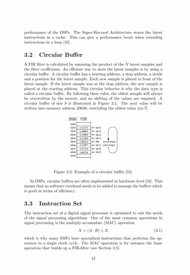
A FIR filter is calculated by summing the product of the N latest samples andthe filter coefficients. An efficient way to store the latest samples is by using acircular buffer. A circular buffer has a starting address, a stop address, a strideand a position for the latest sample. Each new sample is placed in front of thelatest sample. If the latest sample was at the stop address, the new sample isplaced at the starting address. This circular behavior is why the data type iscalled a circular buffer. By following these rules, the oldest sample will alwaysbe overwritten by the newest, and no shifting of the values are required. Acircular buffer of size 8 is illustrated in Figure 3.2. The next value will bewritten into memory address 20046, overriding the oldest value x[n-7].
Figure 3.2: Example of a circular buffer [24].
In DSPs, circular buffers are often implemented at hardware level [24]. Thismeans that no software overhead needs to be added to manage the buffers whichis good in terms of efficiency.
3.3 Instruction Set
The instruction set of a digital signal processor is optimized to suit the needsof the signal processing algorithms. One of the most common operations insignal processing is the multiply-accumulate (MAC) operation
X = (A ·B) +X (3.1)
which is why many DSPs have specialized instructions that performs the op-eration in a single clock cycle. The MAC operation is for instance the basicoperation that builds up a FIR-filter (see Section 2.3).
12

It is also common for DSPs to support special addressing instructions suchas bit reversed addressing and modulo addressing. The bit reversed addressingreverses the bits in the address which is useful in the calculations of the Coley-Tukey FFT. The modulo addressing is used to wrap around when indexing inthe circular buffers (as described in Section 3.2).
3.4 Parallelism
One way for digital signal processors to achieve better performance is by uti-lizing instruction-level parallelism. This can be done with techniques such assuperscalar architecture and Very Long Instruction Words (VLIW).
In a superscalar architecture, the hardware looks for data instructions torun in parallel. The choice of which instructions to run in parallel depends onthe data dependencies between the instructions.
VLIW is another way of achieving instruction level parallelism. In super-scalar achitecture, it is the hardware that looks for operations to run in parallel.In VLIW it is the compiler that does that type of work. Operations that canbe run in parallel is grouped together in one single large instruction. The hard-ware can then execute the VLIW instruction operations in parallel withoutworrying about data dependencies, etc. This means that a similar behavior asin a superscalar architecture is achieved, but the hardware can be simpler andbe made more power efficient. Some drawbacks with this approach is that thecompiler needs to be more complicated and the backward compability is notas good as in an ordinary superscalar architecture.
Another form of parallelism is data level parallelism, which can be achievedby singe instruction multiple data (SIMD) instructions. The SIMD instructionoperates on multiple data instead of single data. The data needs to be non-correlated for SIMD to work. An example use case could be to add all numbersin a list by some constant. The sequential way of doing this would be to iterateover the list in a for loop and increase each element by the constant. Thecorresponding SIMD instruction would utilize multiple arithmetic units andexecute all additions in parallel, which requires fewer clock cycles.
3.5 Floating- and Fixed point
Digital signal processors (DSPs) can either represent numbers by using fixedor floating point representation [24]. In fixed point representation, the decimalpoint has a fixed position, meaning that there are always the same number ofdigits after the decimal point. This results in the representable numbers beinguniformly distributed between the minimum and maximum number.
In floating point representation, the decimal point does not have a fixedposition. A common floating point representation is the IEEE 754 standard[9], which says that a floating point should be represented with a sign, exponent
13

and a significand:(−1)sign · bexponent · significand (3.2)
where b is the base (2 or 10). A 32-bit binary floating point number (b=2)is represented with one sign bit, 8 exponent bits and 23 significand bits. Thesignficand is stored on a fraction format, with an explicit leading one.
Both fixed point and floating point DSPs have their pros and cons. Thefloating point representations offers a more precise representation and is betterfor accurate mathematical operations [24]. The fixed point representation oftenhas cheaper hardware cost at the cost of lost accuracy and more complicateddevelopment (because of underflow, overflow, etc.) [24].
3.6 Cirrus
The Cirrus WM8281 is an audio system with features such as 6 analog or 8digital microphone inputs and 3 stereo outputs [14]. The processor is a quad-core where each core can run at a maximum of 150 MHz [14]. It supportsinteger and fixed-point floating numbers that are 24 and 48 bits long. The24-bit floating point is signed and have 4 integer bits and 20 fraction bitswhile 48-bit representation has twice as many integer and fraction bits [28].An overview image of the ADSP2 core is given in Figure 3.3. The descriptionof the different parts are based on the architecture summary document [27]provided by the manufacturer.
14

Figure 3.3: An overview of the components of the Cirrus core [27].
The core consists of three main components: datapath, address generationunits (AGUs) and program control unit (PCU). The datapath block performscalculations and writes the result back to the registers. It supports basic mathand logic operations as well as more DSP specific operations such as multiply-accumulate and reversed bit addressing.
The address generation units controls the access to three different memories:X, Y and Z. The width of the memories are 24 bits, which means that a 48-bitdata type takes two clock cycles to retrieve. The X memory is the standardlocation for variables, while the Y memory is an extra read/write memoryin which global variables can be annotated to be located to. The Z memoryis a read only memory and are used to retrieve constants. The sizes of thememories varies between the different cores in the WM8281 as shown in Table3.1. Core 2 and 3 are designed to run more advanced programs and thereforehave bigger memories. The address generation units supports efficient circularbuffer traversing.
The program control unit retrieves the instructions from memory. Theprogram memory is 40 kB for cores 1 and 4 and 100 kB for cores 2 and 3.The PCU retrieves two 20-bit instructions or one 40-bit instruction at a time.One of its features is the zero overhead for-loop which means that the for-loopoverhead is handled at hardware level and does not consume any extra clock
15

Core 1 Core 2 Core 3 Core 4P (kByte) 40 100 100 40X (kByte) 48 72 108 48Y (kByte) 12 72 12 12Z (kByte) 12 12 12 12Total (kByte) 729
Table 3.1: The different sizes of X, M and Y memory in the four cores of CirrusWM8281 [14].
cycles. The PCU supports two levels of zero overhead-loops before it needs tohandle the for loops with code [27].
3.7 Tensilica HIFI3 DSP
The Tensilica HiFi DSP family contains multiple members [7], but this sectionwill focus on the DSP used by the audio processor DA14195A from Dialog,namely the HiFi 3 DSP. The HiFi 3 DSP can be run up to 290 MHz in theDA149195A configuration [15]. It is based on the Harvard architecture anduses 16- and 24-bit instructions [15]. The DSP also supports 64-bit VLIWinstructions that can execute three instructions in parallel [3]. The processoruses fixed-point number representation and supports 16-, 24-, 32- and 64-bitrepresentations [15]. The processor features multiple MAC-units and supportstwo 32x32 or four 24x24/16x16 multiply-accumulates per clock cycle [3].
The DA14195A has a total of 256 kB DSP RAM and two load/storage unitsthat handles the data memory access [15].
3.8 ARM Cortex-A9
The ARM Cortex-A9 is a general purpose processor that runs TrueVoice. Theprocessor is designed to suit applications that requires low power consumption,such as mobile phones [4]. The following information was retrieved from theCortex-A9 Technical Reference Manual [11].
The Cortex-A9 is a 32-bit processor that implements the ARMv7-A archi-tecture. It supports instructions that are 32 and 16 bits long but can also beextended with 128-bit SIMD instructions to achieve data level parallelism. Theprocessor architecture is dual-issue superscalar which means that two instruc-tions can be run in parallel. The architecture can be modified to support upto four cores. The processor cores features a floating point unit that supportsfloating point operations on 32- and 64-bit floating numbers. The floating pointnumbers are represented according to the IEEE 754 standard [9].
The architecture is based on the modified Harvard architecture, with sep-arate L1 caches and buses for data and instructions. The sizes of the two L1
16

caches can be configured to be between 16 and 64 kB.
17


Chapter 4
Accomplishment
This section describes the different steps in the project: how the planning wasmade, how it was executed and what was the outcome of the different parts.
4.1 Preliminaries
Some questions that needed to be answered before starting the practical workwas:
– What properties of the candidates should be evaluated?
– What should be tested in practice?
– Which processors should be prioritized?
The first question was answered quite early in the process, after discussingwith one of the TrueVoice engineers. The decision was made to focus on threedifferent requirements: processing power, memory and number representation.The processing power is about finding out if the processor is fast enough torun the TrueVoice algorithms in real time. The memory requirements is aboutfinding out if all the buffers that are used in TrueVoice fits in the memoryof the DSP. The number representation aspect is about fixed-point numberrepresentation. A fixed-point number representation using few bits can giveunwanted behavior (in the FFT for instance) if no precautions are taken.
The processing power can be tested in different ways. The best thing wouldbe to port the whole TrueVoice to the candidates, but unfortunately that wouldtake too much time. Instead the decision was made to take out some crucialparts of TrueVoice and test them separately. The decision was made to test twoof the main components in TrueVoice: the NLMS filtering used in the acousticecho cancellation and the FFT that splits the fullband signal into subbands.
The decision was made to only test the processing power in practice. Thememory requirements mostly depends on the size of different buffers, which can
19

be calculated in theory. Optionally, the memory usage of an existing solutioncould have been tested in practice. But focus was chosen to be put on theprocessing power since the theoretical value of the execution speeds are harderto predict.
Which processors to focus on was a decision that was made on a higherlevel of the company. The decision was mainly based on what architecturesthat were best from a strategic perspective. The two top candidates that werechosen were Cirrus and Tensilica. It was also decided to add ARM Cortex-A9,which already runs TrueVoice, to the list of candidates. By comparing theother candidates with Cortex-A9, it will be easier to make conclusions abouthow TrueVoice actually would work.
With these things in mind, the following requirements were put on the testprogram. The key words ”MUST”, ”MUST NOT”, ”REQUIRED”, ”SHALL”,”SHALL NOT”, ”SHOULD”, ”SHOULD NOT”, ”RECOMMENDED”, ”MAY”,and ”OPTIONAL” in this document are to be interpreted as described in RFC2119 [13]. The test program
R1 MUST implement a signal processing routine with similar characteristicsto TrueVoice.
R2 MUST measure wall-clock execution time of processing a fixed size signalsample.
R3 MUST be implemented on Cirrus architecture.
R4 MUST be implemented on ARM Cortex-A9 processor.
R5 SHOULD utilize hardware specific optimization techniques.
R6 SHOULD be implemented on Tensilica architecture.
R7 MAY be implemented on Qualcomm architecture.
R8 MAY be implemented on CSR architecture.
R9 MAY be implemented on Dilogic architecture.
4.2 How the Work was Done
Due to time limitations, the test program was only implemented on the CirrusWM8281 and ARM Cortex-A9 (integrated on an i.M6Q board) processor. TheCirrus was configured to run at maximum clock rate (147 MHz) while the ARMCortex-A9 was run at default speed (792 MHz).
The execution time of the ARM was measured by retrieving the wall-clocktime before and after the function call and then calculating the difference be-tween the two time points. The Cirrus WM8281 does not have any clock ortimer functionality. Instead, the solution was to count the number of function
20

calls that was made during some fixed time period and then divide the fixedtime with the number of function calls to get time per function call. Withother words, if N number of executions are made in X seconds, then eachexecution takes X/N seconds to execute. The Cirrus test program was alsoevaluated in theory by analyzing the generated assembly code and calculatingthe number of clock cycles to run the program. The theoretical evaluation ofthe different architectures was mostly done by reading data sheets about thespecific processor.
The focus of the project was with other words to fulfill requirements R1to R5 while requirements R6 to R9 were omitted. How well the requirementswere fulfilled is discussed in Section 6.1.
21

Chapter 5
Results
This section describes the implemented test program as well as the resultsof running the tests on different architectures. The three different evaluationcriteria are memory usage, number representation and processing power.
5.1 Test Program
The test program tests two of the main parts of the TrueVoice algorithm: aNormalized Least Mean Square (NLMS) filter and a Fast Fourier Transform(FFT). TrueVoice performs the NLMS filtering on the subbands extracted bythe FFT, but these parts were separated in the test program.
The test program was implemented on two different architectures: CirrusWM8281 and ARM Cortex-A9. Because of the fundamental differences be-tween the two architectures, two separate programs had to be implemented.
5.1.1 Cirrus
The Cirrus test program was implemented by using the provided signal pro-cessing library. The most complex part of the NLMS function is run N ·(M−1)times, where N is the number of input samples and M is the filter length. Theprovided signal library implemented this part using four cycles:
(1) r2 = *(i2 - m0 \% l0)
(2) a1 = rnd(r0 * r2), r2 = *y:i1
(3) r2 = fix(r2 + a1), r1 = *i2
(4) a0 += r1 * r2, *y:(i1 -= m0) = r2
Line 1 is traversing the delay line of the filter, retrieving delayed inputsand storing them in a register r2. Line 2 computes the coefficient change whileretrieving the old coefficient. The coefficient change is calculated by multiplying
23

the delayed input stored in r2 with the pre-calculated constant c = µe(n)ε+uH(n)u(n)
stored in register r0. Line 3 is calculating the new coefficient value (and storingit in register r2) while retrieving the delayed input again (storing it in registerr1). Line 4 is calculating the new output of the FIR filter by adding the productof the delayed input (r1) and the new coefficient (r2) to register a0. The secondpart of line 4 is writing the new coefficient value to memory.
The FFT function was implemented using the same signal library, but with-out doing the same research on the assembly code.
5.1.2 ARM
The ARM test program uses a custom NLMS implemention that is basedon the NLMS filter used in TrueVoice. The program was compiled usingarm-poky-linux-gnueabi (GCC) version 5.2.0.
The program has two separate loops for the calculation of the output of theFIR-filter and the update of the filter coefficients:
/* Output of fir filter */
for(i=0;i<FILTER_LENGTH;i++) {
temp += coefs[i]*dly[idx + i];
}
...
/* Update coefficients */
for(i=0;i<FILTER_LENGTH;i++) {
coefs[i] += BETA*dly[idx + i];
}
where coefs is an array with the filter coefficients, idx is the index of theoldest sample, dly is an array with the delayed input samples and BETA is thefilter step size. The instructions inside the loops are executed N ∗M times,where N is the number of inputs and M is the filter length.
The FFT test uses the same FFT library as the TrueVoice ARM imple-mentation, namely the FFT open source library Kiss FFT [5]. It was compiledusing similar flags to the NLMS.
5.2 Test Results
The execution times of performing an NLMS filter with different filter lengthson the two architectures are illustrated in Figure 5.1. The Cirrus performsthe filtering in about twice as long time as the ARM (2.4 times slower withfilter length 32 and 1.5 times slower with filter length 4,200). The relation
24

between the execution times are illustrated in greater detail in Figure A.1 inthe appendix.
Figure 5.1: Execution times for Cirrus and ARM when filtering 16,000 sampleswith NLMS filters of various lengths.
The execution times of the FFT tests are illustrated in Figure 5.2. With128 points, the execution takes about 3.3 times longer on the Cirrus. In termsof absolute numbers, the execution times differs with about 2 ms. The relationbetween the execution times are illustrated in greater detail in Figure A.2 inthe appendix.
25

Figure 5.2: Execution times for Cirrus and ARM when performing FFT trans-forms of various sizes on 16,000 samples.
5.3 Memory Usage
The biggest part of the memory usage of TrueVoice is the buffers of the acousticecho cancellation (AEC) algorithm. For each subband, the microphones have abackground and a foreground filter and a shared delay buffer. This gives (1 +2 ·M) number of buffers per subband, where M is the number of microphones.If there are B number of subbands and each buffer is L words long, then thetotal size of the buffers are:
2 · (1 + 2 ·M) ·B · L (5.1)
To calculate the theoretical memory usage of the Cirrus AEC buffers, thenumber of subbands and the filter length must be known for both the lowsubbands for the FAP algorithm and the high subbands for the NLMS. A goodcandidate to retrieve these numbers from are the Sharc DSP implementation.The Sharc implementation uses the values shown in Table 5.1.
With only one microphone, this means that the total size of the FAP buffersis 2 ∗ (1 + 2 ∗ 1) ∗ 22 ∗ 72 = 9504 words, and the size of the NLMS buffers is2 ∗ (1 + 2 ∗ 1) ∗ 43 ∗ 32 = 8256 words. This gives a total AEC buffer size of9504 + 8256 = 17760 words. The word size of Cirrus WM8281 is 24 bits, whichmeans that 17760 words corresponds to 53 820 bytes. The total memory usagefor 1 to 4 microphones are shown in Table 5.2.
26

Number of FAP subbands 22FAP filter length 72Number of NLMS subbands 43NLMS filter length 32
Table 5.1: Number of FAP and NLMS subbands and their respective lengthsfor the Sharc DSP implementation.
Number of mics Memory usage (B)1 53 8202 88 8803 124 3204 159 840
Table 5.2: Cirrus memory usage for AEC buffers with same number of subbandsand filter lengths as the Sharc DSP implementation.
5.4 Number Representation
Cirrus WM8281 works with 24-bit fixed-point number representation. Themain issue with using fixed-point numbers in the TrueVoice algorithm is therisk of overflow when performing the FFT. To avoid saturation in the FFTalgorithm, the numbers that are added in each step of the Butterfly diagramare divided by two, which results in that one bit of precision is lost. TrueVoiceuses 128 subbands in its FFT. This means that the Butterfly algorithm useslog2(128) = 7 number of steps and that 7 bits of precision are lost. However,the Cirrus WM8281 uses a 24-bit representation of its fix-point numbers andthe sound sampling is only 16 bits. This means that the 8 extra bits can beused to avoid saturation.
27


Chapter 6
Conclusions
This chapter contains a discussion about the result of the project.
6.1 Discussion
The Cirrus NLMS filtering took about twice as long as the ARM NLMS filter-ing. However, the ARM clock rate is about five times higher than the Cirrusclock rate which indicates that the Cirrus could utilize its clock cycles moreefficiently. The main reason for the Cirrus not being five times slower is prob-ably due to the fact that its instruction set is optimized for signal processing,while the ARM instruction set is not. The ARM’s general purpose memoryarchitecture could also have slowed down its processing speed, because of slowmemory access due to cache misses. It is also possible that the ARM processingwas slowed down by the operating system consuming clock cycles.
The test program implemented two of the main parts of the acoustic echocancellation algorithm in TrueVoice and hence fulfilled requirement R1. Re-quirement R2 said that the test program must measure the wall-clock execu-tion time of processing a fixed signal sample. This was achieved in two differentways: the ARM processor could measure the execution time with built-in li-brary functions while the execution time of the Cirrus processor was measuredas described in Section 4.2. By measuring the time in a longer period the resultsare probably accurate enough to make the statement that R2 was achieved aswell. Requirements R3, R4 and R6 stated that the test program should beimplemented on Cirrus, Tensilica and ARM processors. In reality, the testprogram was run only on the Cirrus and ARM because of time limitations.Another approach would have been to focus on the Cirrus and Tensilica, butthe decision to include the ARM instead of the Tensilica was mostly based ontwo things. First, the ARM is a multi-purpose processor that can run commonC-code which makes it faster to get things running. Second, TrueVoice alreadyruns on ARM so by comparing the Cirrus with ARM instead of with Tensilica
29

makes it easier to say something about how well TrueVoice can be run on theprocessor, instead of just make a conclusion on which one of the Cirrus andTensilica that has best performance. But the best thing would be to implementthe program on all three processors.
Requirement R5 stated that the test program should utilize hardware spe-cific optimization techniques. On the Cirrus platform this was achieved byusing the built-in library functions for the NLMS and FIR functions. Theprobability that the manufacturer of the processor can utilize the hardwarebetter than a rookie is quite high. The generated microcode showed differ-ent hardware optimizations such as zero-overhead for loops and circular bufferaddressing. The ARM processor test program uses similar functions that arealready used in TrueVoice. In this case, performance that was more similar tothe current implementation felt more relevant than to create the most efficientone.
Requirements R7, R8, R9 were about implementing the test program onthree more architectures. Because of limited time resources, the decision toskip those processors were made quite early. More processors in the evaluationhad probably resulted in a more interesting comparison however.
The execution time of the ARM was measured with built-in functions whilethe execution time of the Cirrus was made by counting the number of functioncalls made during a fixed time period. The Cirrus tests were performed in prac-tice by manually stopping the program after five minutes. A better approachwould have been to automatize this process. However, the test results them-selves proved to be very close to the theoretical values. Another improvementof the method would have been to complement the ARM wall-clock executiontime measurements by counting the number of clock ticks used by the program.That approach would have excluded the clock cycles used for operating systemlevel operations and would make a comparison between the implementationseasier. A greater understanding of the ARM implementation could also havebeen achieved by running the code in a simulator and compare it with theCirrus simulation results.
6.2 Conclusions
The aim of this project was to find the most suitable candidate to port TrueVoiceto. In reality, most of the focus was put on evaluating if it is possible to runTrueVoice on the Cirrus WM8281. The results from running the test programshowed that the NLMS filtering took about twice as long to run on the Cir-rus compared with the ARM. The ARM can process four microphones whichmeans that the processing power of the Cirrus should be able to handle abouttwo microphones. The calculated memory requirements of the AEC buffersshowed that one microphone would require 54 kB of memory while two micswould require 89 kB. However, other parts of TrueVoice consumes memory aswell, which means that core 1 and 4 probably do not have enough memory to
30

run the processing. Core 2 seems to have enough memory to handle one mi-crophone while core 3 should be able to handle one to two microphones. Withother words should the two cores be able to process two to three microphones intotal. The fixed-point issues in the FFT should not be of any problem since thearchitecture uses a 24-bit number representation. With these things in mind,the conclusion is that Cirrus WM8281 is a good candidate to port TrueVoiceto.
6.3 Future Work
The future work of this subject could either go wider or deeper. A wider ap-proach would be to include more of the candidates listed in the requirements.This would result in a better comparison. The deeper approach would be tostart porting different parts of the TrueVoice code while continuously perform-ing measurements of performance and memory usage. The final step in thiscase would be to port the whole program.
It would also be interesting to evaluate more aspects such as how easy thedevelopment tools of the different architectures are to use.
31


References
[1] The action of the fourier transform. [Illustration]http://www.revisemri.com/questions/creating an image/fourier transform.Accessed: 2016-05-16.
[2] Audio sampling. [Illustration] https://www.videomaker.com/article/c4/14524-digital-audio-sampling. Accessed: 2016-05-16.
[3] Cadence Tensilica HiFi DSP Configurable pro-cessors for audio, voice, and speech processing.http://ip.cadence.com/uploads/928/Cadence Tensilica HiFi DSP DS final-pdf. Accessed: 2016-05-01.
[4] Cadence Tensilica HiFi DSP Configurable processors for audio, voice, andspeech processing. http://www.arm.com/cortex-a9.php, note = Accessed:2016-05-19.
[5] Kiss FFT. https://sourceforge.net/projects/kissfft/. Accessed: 2016-05-02.
[6] Least mean square filter. [Illustration]https://en.wikipedia.org/wiki/Least mean squares filter. Accessed:2016-05-16.
[7] Tensilica HiFi Audio/Voice DSP IP. http://ip.cadence.com/ipportfolio/tensilica-ip/audio. Accessed: 2016-05-01.
[8] Von neumann vs harvard architecture. [Illustration]http://www.spiroprojects.com/blog/cat-view-more.php?id=130. Ac-cessed: 2016-05-16.
[9] IEEE Standard for Floating-Point Arithmetic. IEEE Std 754-2008, pages1–70, August 2008.
[10] Maria Elena Angoletta. Digital signal processor fundamentals and systemdesign. CERN Document Server, 2007.
[11] ARM Holdings. Cortex A9 - Technical Reference Manual, 6 2012. Rev.r4p1.
33

[12] Limes Audio. Internal documentation.
[13] S. Bradner. IETF RFC 2119: Key words for use in RFCs to IndicateRequirement Levels. Technical report, Internet Engineering Task Force(IETF), 1997.
[14] Cirrus Logic. WM8281 Datasheet, 2015. Rev. 3.1.
[15] Dialog Semiconductor. Audio processor with ARM, HiFi-3, USB & Powermanagement, 1 2016. Rev. 5.
[16] F. Alton Everest. Master Handbook of Acoustics. McGraw Hill Profes-sional, May 2001.
[17] S. L. Gay and S. Tavathia. The fast affine projection algorithm. In ,1995 International Conference on Acoustics, Speech, and Signal Process-ing, 1995. ICASSP-95, volume 5, pages 3023–3026 vol.5, May 1995.
[18] Richard A. Haddad and Thomas W. Parsons. Digital Signal Processing:Theory, Applications, and Hardware. Computer Science Press, January1991.
[19] John W. Tukey James W. Cooley. An algorithm for the machine calcula-tion of complex fourier series. Mathematics of Computation, 19(90):297–301, 1965.
[20] P. Lapsley and G. Blalock. How to estimate DSP processor performance.IEEE Spectrum, 33(7):74–78, July 1996.
[21] Philipos C. Loizou. Speech Enhancement: Theory and Practice. Taylor &Francis, June 2007.
[22] John G. Proakis and Dimitris G. Manolakis. Digital Signal Processing:Principles, Algorithms, and Applications. Prentice Hall, 1996.
[23] C.E. Shannon. Communication In The Presence Of Noise. Proceedings ofthe IEEE, 86(2):447–457, February 1998.
[24] Steven W. Smith. The Scientist and Engineer’s Guide to Digital SignalProcessing. California Technical Pub., 1997.
[25] Himanshu Soni. Proceedings of the 2009 International Conference on Sig-nals, Systems and Automation (ICSSA 2009). Universal-Publishers, April2010.
[26] Ethan Winer. The Audio Expert: Everything You Need to Know AboutAudio. CRC Press, November 2012.
[27] Wolfson Microelectronics. ADSP2 Architecture Summary, 2013.
[28] Wolfson Microelectronics. ADSP2 C Layer Guide, 2015.
34

Appendix A
Test Results
A.1 Relative Execution Times NLMS
Figure A.1: The execution time for Cirrus divided by the execution time forARM when filtering 16,000 samples with NLMS filters of various lengths. Thenormalized line illustrates the theoretical ratio if both processors had the sameclock rate.
35

A.2 Relative Execution Times FFT
Figure A.2: The execution time for Cirrus divided by the execution time forARM when performing FFT transforms of various sizes on 16,000 samples. Thenormalized line illustrates the theoretical ratio if both processors had the sameclock rate.
36