Performance evaluation and design of 5G communication ...
10
Performance evaluation and design of 5G communication‑based millimeter wave antenna Mustafa Shakir 1* , Sohaib Aslam 1 , M. Usman Sarwar 1 , Muhammad Adnan 2 and Muhammad Rafay Khan 1 1 Introduction With the extensive use of wired and wireless communication devices according to Statista reports, 1.5 billion smart phones have been sold during recent years [1]. Mobile communication markets have been growing tremendously according to GSMA, 5.19 bil- lion subscribers in the world have access to the limited bandwidth resources, which is also a motivating factor toward adoption of new technology trends. Since data rate is one of the essential performance parameters in antenna theory in which a better per- forming transmitter, channel and receiver work in coordination in a communication system. Hence, the improved elements leads to the development of next generation as shown in Fig. 1. e upcoming 5G technology not only provides greater reliability, higher data rates up to 20 Gbps and reduced power consumption to meet the massive increase in connected devices but also promises to increase the visions of emerging technologies such as virtual Abstract Multiple categories of electronic devices have been introduced recently in response to the demands and developments in the industry. Around 5.19 billion telecom services subscribers today have a significant effect on the allocation and utilization of band- width, and hence, there is extensive need to use higher-frequency bands, e.g., mm band to achieve the required quality of service since there is extensive need to shift the paradigm to the next generation. For 5G networks, antenna structuring and designing is an integral part of the communication system. In antenna theory, improving antenna gain is important to attain isotropic antenna, antenna gain can be improved by the controlled behavior of frequencies, beam forming and choosing the right antenna fabric. Through antenna design using different substrates thickness, the propagation losses are examined in order to determine the variation with radiation characteristics. In this way, the examination of the 5G mm-wave spectrum with comparative analysis of input impedance, gain and radiation efficiency is shown through mathematical modeling. Using this approach, the antenna efficiency is improved by up to 20% with increase in substrate thickness. Different antenna arrays have been designed for effec- tive improvement in reflection coefficients. The results are obtained using simulation of antenna in CST and high-frequency structure simulator. Keywords: Antenna array, Beam forming, Gain, Propagation loss, 5G Open Access © The Author(s), 2021. Open Access This article is licensed under a Creative Commons Attribution 4.0 International License, which permits use, sharing, adaptation, distribution and reproduction in any medium or format, as long as you give appropriate credit to the original author(s) and the source, provide a link to the Creative Commons licence, and indicate if changes were made. The images or other third party material in this article are included in the article’s Creative Commons licence, unless indicated otherwise in a credit line to the mate- rial. If material is not included in the article’s Creative Commons licence and your intended use is not permitted by statutory regulation or exceeds the permitted use, you will need to obtain permission directly from the copyright holder. To view a copy of this licence, visit http:// creativecommons.org/licenses/by/4.0/. RESEARCH Shakir et al. J Wireless Com Network (2021) 2021:179 https://doi.org/10.1186/s13638‑021‑02052‑9 *Correspondence: [email protected] 1 Department of Electrical Engineering, Superior University, Lahore 54000, Pakistan Full list of author information is available at the end of the article
Transcript of Performance evaluation and design of 5G communication ...

Performance evaluation and design of 5G communication‑based millimeter wave antennaMustafa Shakir1* , Sohaib Aslam1, M. Usman Sarwar1, Muhammad Adnan2 and Muhammad Rafay Khan1
1 IntroductionWith the extensive use of wired and wireless communication devices according to Statista reports, 1.5 billion smart phones have been sold during recent years [1]. Mobile communication markets have been growing tremendously according to GSMA, 5.19 bil-lion subscribers in the world have access to the limited bandwidth resources, which is also a motivating factor toward adoption of new technology trends. Since data rate is one of the essential performance parameters in antenna theory in which a better per-forming transmitter, channel and receiver work in coordination in a communication system. Hence, the improved elements leads to the development of next generation as shown in Fig. 1.
The upcoming 5G technology not only provides greater reliability, higher data rates up to 20 Gbps and reduced power consumption to meet the massive increase in connected devices but also promises to increase the visions of emerging technologies such as virtual
Abstract
Multiple categories of electronic devices have been introduced recently in response to the demands and developments in the industry. Around 5.19 billion telecom services subscribers today have a significant effect on the allocation and utilization of band-width, and hence, there is extensive need to use higher-frequency bands, e.g., mm band to achieve the required quality of service since there is extensive need to shift the paradigm to the next generation. For 5G networks, antenna structuring and designing is an integral part of the communication system. In antenna theory, improving antenna gain is important to attain isotropic antenna, antenna gain can be improved by the controlled behavior of frequencies, beam forming and choosing the right antenna fabric. Through antenna design using different substrates thickness, the propagation losses are examined in order to determine the variation with radiation characteristics. In this way, the examination of the 5G mm-wave spectrum with comparative analysis of input impedance, gain and radiation efficiency is shown through mathematical modeling. Using this approach, the antenna efficiency is improved by up to 20% with increase in substrate thickness. Different antenna arrays have been designed for effec-tive improvement in reflection coefficients. The results are obtained using simulation of antenna in CST and high-frequency structure simulator.
Keywords: Antenna array, Beam forming, Gain, Propagation loss, 5G
Open Access
© The Author(s), 2021. Open Access This article is licensed under a Creative Commons Attribution 4.0 International License, which permits use, sharing, adaptation, distribution and reproduction in any medium or format, as long as you give appropriate credit to the original author(s) and the source, provide a link to the Creative Commons licence, and indicate if changes were made. The images or other third party material in this article are included in the article’s Creative Commons licence, unless indicated otherwise in a credit line to the mate-rial. If material is not included in the article’s Creative Commons licence and your intended use is not permitted by statutory regulation or exceeds the permitted use, you will need to obtain permission directly from the copyright holder. To view a copy of this licence, visit http:// creat iveco mmons. org/ licen ses/ by/4. 0/.
RESEARCH
Shakir et al. J Wireless Com Network (2021) 2021:179 https://doi.org/10.1186/s13638‑021‑02052‑9
*Correspondence: [email protected] 1 Department of Electrical Engineering, Superior University, Lahore 54000, PakistanFull list of author information is available at the end of the article

Page 2 of 10Shakir et al. J Wireless Com Network (2021) 2021:179
reality and smart cities [3]. To continue deployment and operation in limited frequency bands is not a feasible solution, hence International Telecommunication Union (ITU) till mid of 2018 made certain standards to launch 5G thus millimeter frequency bands will be allocated for 5G backhaul links in order to fulfill the 5G expectations where large bandwidths are required. These are illustrated in Fig. 2.
In order to operate over a frequency band, the antenna should be compliant with cer-tain standards supported by regulatory bodies such as European Telecommunications Standards Institute (ETSI) [5] and the United States Federal Communications Commis-sion (FCC). These standards have limitations on different characteristics of the antenna, such as its minimum gain and maximum effective isotropic radiated power (EIRP). Also, the antenna radiation pattern should be accommodated with a radiation pattern enve-lope (RPE) of a certain class. The class of RPE to be supported depends on the local regulators. The goal of these requirements is to avoid interference within a network and control the effects on other networks operating in the neighboring bands [6].
Hence in the modern era, the prominent increase of wireless devices, insufficient bandwidth and limited channel capacity has substantially promoted efforts to develop advanced standards for communication networks. Consequently, the development of next generation means much better channel capacity and higher data rates by using a millimeter spectrum to characterize the performance of antennas to meet the above-mentioned objectives for which certain parameters should be kept in mind while designing antennas. Antenna parameters can be classified into two categories, firstly the antenna parameters according to the field point of view which include the radiation
1G 1870 - 1980
•Analog signal and voice call only
2G 1980 - 1990
•Digital Signal SMS and MMS
•Data speeds of up to 64 kbps
3G 1990 - Deployed
•Mobile Data
•Speed of up to 2 Mbps.
4G Deployed technology
•Mobile Data Broadband
•Quality of Service
5G 2020 - ?
•High Speed data
•IoT •Massive
network capacity
Fig. 1 Mobile network generations evolution in time [2]
0
50
100
150
200
250
300
350
Traditional Sub Bandsλ = 50mm
mm Wave Bandλ = 10 mm to 1mm
V Band E Band
Min Frequency Max Frequency
Fig. 2 Frequency spectrum [4]

Page 3 of 10Shakir et al. J Wireless Com Network (2021) 2021:179
pattern, beam width, directivity, gain, bandwidth and the polarization, and the remain-ing antenna performance parameters are according to the circuit point of view which include input impedance, radiation resistance and reflection coefficient, return loss, VSWR and bandwidth [7–9]. Authors in [10] have worked on various channel models for diverse applications thus with the proper beamforming approaches for enhanced coverage. Current techniques have been presented by authors in [11] for enhancing the performance parameters of patch antennas for 5G implementation at mmW frequencies with performance parameters including gain, bandwidth among antenna elements for MIMO systems. Since the design considerations are vital in terms of an extended semi-circular structure which is also beneficial in enhancing the directional radiation of the antenna [12], the need for evaluating multiplexing performance in 5G Ultra Dense net-works for interference suppression rate as a relation of signal of interest (SOI) to signal not of interest (SNOI) with preliminary angular separation has been considered in [13]. For guaranteeing effective coverage in mmW communication systems, the distributed antenna systems and cooperative multi-hop relaying with designing of antenna arrays have been presented in [14]. Hence to achieve an optimized antenna, antenna design-ing parameters are the key factor in improving antenna performance and that is why the antenna substrate is kept in observation. In [15] with the selection of Øn = un would result in deterministic width W for which the scaling properties can be thoroughly examined in detail according to the representation with the use of Poisson summation formula. In [16] the entropies of Shannon, Renyi and Kolmorov are examined in detail and with their comparative performance along with pre-fractal shape, the antennas are evaluated since the entropy is interdependent on the fractal geometrical shape and the physical performance of the antennas. The authors in [17] have worked on the model of joint time-frequency-shape management of discrete-time signals using discrete shape-let transform (DST) which makes it possible to realize the time support of frequencies along with investigating the shape simultaneously thus making it possible to synchronize applications in a diversity of fields in signal processing. In [18] the authors have pre-sented a wavelet expansion theory for positive definite distributions on the real line and derived a fractional derivative operator thus the computation of Gabor–Morlet wavelet with its main characteristics. Since the broadband applications are significant so authors in [19] have developed and verified a broadband planar Sierpinski fractal antenna for multiband applications which according to its defined dimensions results in optimal return losses, radiation patterns and gain of the proposed antenna. With the importance of investigating the general implementation of the Sierpinski gasket through the har-monic metric in line with the geometric configuration of small antennas thus its perfor-mance is evaluated with the associated entropy.
2 Methods and experimentationSubstrate thickness We have chosen a low-loss Teflon-based material from the CST STUIDIO SUITE library for the study of the impact of the substrate thickness on antenna performance. This substrate has a dielectric constant and εr = 2 and loss tan-gent tan = 0.0007. An edge-fed microstrip patch antenna was used in the study as shown in Figs. 3 and 4. The antenna dimensions were slightly adjusted for each substrate thick-ness so that the antenna resonates at 28 GHz. It can be seen from Fig. 3 that as the

Page 4 of 10Shakir et al. J Wireless Com Network (2021) 2021:179
substrate thickness increases from 0.127 to 0.787 mm, the real part of the input imped-ance increases from 207 to 322 at 28 GHz. This increase in the real part of the antenna impedance can be recognized to an increase in the antenna radiation efficiency. The real part of the antenna input impedance can be written as
where RA , the total real part of the antenna input impedance; Rr , Radiation resistance which represents the part of the input power of the antenna that is transferred into radi-ated electromagnetic waves; Rloss , the part of the antenna input resistance (conductor losses, dielectric losses, surface waves, etc.).
3 Designing rectangular microstrip antennaDesigning a rectangular microstrip antenna involves choosing the material of substrate with thickness “h,” target center resonant frequency “fr” in Hz and the dielectric permit-tivity constant “ εr ,” we determine the antenna dimensions: antenna width W. This can be calculated in the following steps [20].
Step 1: For efficient radiator, calculate the width W from Eq. (1).
where “C” is the free space light velocity. From the expression we find that that width of the antenna substrate has inverse relation with the resonant frequency, but an optimized substrate thickness can be determined by considering multiple values of thickness.
Step 2: The effective dielectric constant εeff or the effective relative permittivity can be approximated by using Eq. (2).
RA = Rr + Rloss
(1)W =C
2fr
√
2
εr + 1
Fig. 3 Simulated real parts of the antenna input
Fig. 4 Simulated imaginary parts performance of the antenna input impedance for five different substrate thicknesses

Page 5 of 10Shakir et al. J Wireless Com Network (2021) 2021:179
The above expression is an empirical expression of the material property h/W, where “W” is the width of the strip and “h” is the substrate thickness.
Step 3: Determine the incremental length �L generated by the fringing fields from Eq. (3), due to the fringing effect the patch of the antenna seems larger as compared to its physical dimensions. Hence, �L can be given as:
Step 4: Determine the effective length Leff of the patch using Eq. (4) showing its dependence on C, i.e., free space light velocity, effective dielectric constant εeff and reso-nant frequency fr, then determine the actual length L of the patch using Eq. (5)
Using these relations, the antenna can be simulated using simulation tools such as ADS Agilent, CST or high-frequency structure simulator (HFSS) and its performance parameters can be adjusted in order to obtain optimum operational characteristics.
4 Discussion on performance evaluation and resultsSubstrate thickness A low-loss Teflon-based material was chosen from the CST STU-IDIO SUITE library for the study of the impact of the substrate thickness on antenna performance. This substrate has a dielectric constant and εr = 2 (6) and loss tangent tan = 0.0007. An edge-fed microstrip patch antenna was used in the study as shown in Figs. 3 and 4. Figures 3 and 4 present the simulated real and imaginary parts of an antenna input impedance for five different substrate thicknesses, respectively. The sim-ulated input impedance is referenced at ref. plane 1 (see Fig. 3). The antenna dimen-sions were slightly adjusted for each substrate thickness so that the antenna resonates at 28 GHz. It can be seen from Fig. 3 that as the substrate thickness increases from 0.127 to 0.787 mm, the real part of the input impedance increases from 207 to 322 at 28 GHz. This increase in the real part of the antenna impedance can be recognized to an increase in the antenna radiation efficiency. The real part of the antenna input impedance can be written as
where RA , the total real part of the antenna input impedance; Rr , radiation resistance which represents the part of the input power of the antenna that is transferred into
(2)εeff =εr + 1
2+
εr − 1
2
√
1+ 12hW
(3)�L = 0.412h
(
εeff + 0.3
)(
hW + 0.264
)
(
εeff − 0.258
)(
hW + 0.8
)
(4)Leff =C
2fr√εeff
(5)L = Leff − 2�L
(7)RA = Rr + Rloss
Page 6 of 10Shakir et al. J Wireless Com Network (2021) 2021:179
radiated electromagnetic waves; Rloss , the part of the antenna input resistance (conduc-tor losses, dielectric losses, surface waves, etc.).
The simulated radiation efficiency is presented in Fig. 5. It can be seen from the figure that the radiation efficiency rises from 81 to 92.8% with the change of substrate thick-ness from 0.127 mm to substrate thickness of 0.381 mm respectively. This increase in radiation efficiency explains the increase in antenna resistance from 207 Ω at 0.127 mm substrate thickness to 241 Ω at 0.381 mm substrate thickness.
The efficiency then starts to decrease again and reaches an efficiency of 88.2% at a sub-strate thickness of 0.787 mm.
As the microstrip patch is very close to the ground plane which means low thickness that’s why the low efficiency at 0.127 mm substrate thickness is observed. Therefore, the electric field lines are strongly attached to the ground plane.
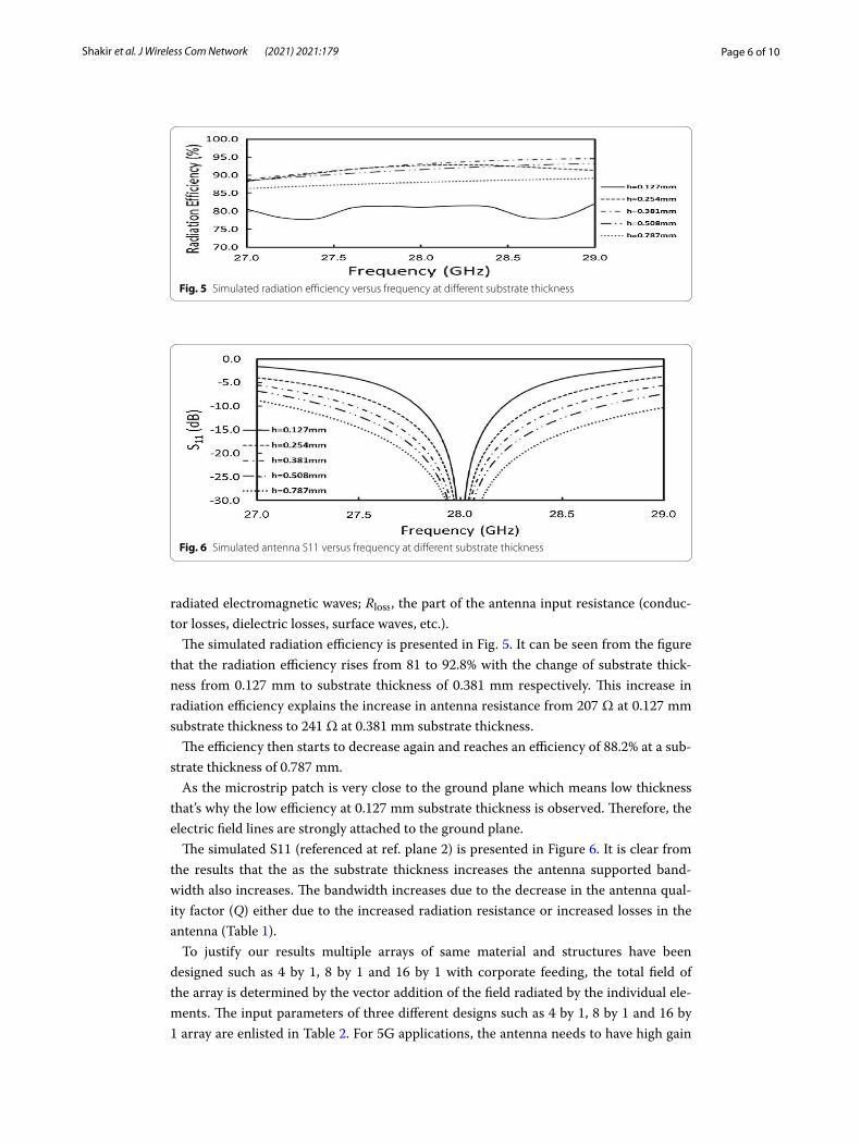
The simulated S11 (referenced at ref. plane 2) is presented in Figure 6. It is clear from the results that the as the substrate thickness increases the antenna supported band-width also increases. The bandwidth increases due to the decrease in the antenna qual-ity factor (Q) either due to the increased radiation resistance or increased losses in the antenna (Table 1).
To justify our results multiple arrays of same material and structures have been designed such as 4 by 1, 8 by 1 and 16 by 1 with corporate feeding, the total field of the array is determined by the vector addition of the field radiated by the individual ele-ments. The input parameters of three different designs such as 4 by 1, 8 by 1 and 16 by 1 array are enlisted in Table 2. For 5G applications, the antenna needs to have high gain
Fig. 5 Simulated radiation efficiency versus frequency at different substrate thickness
Fig. 6 Simulated antenna S11 versus frequency at different substrate thickness

Page 7 of 10Shakir et al. J Wireless Com Network (2021) 2021:179
Tabl
e 1
Sim
ulat
ed a
nten
na p
aram
eter
s at
diff
eren
t sub
stra
te th
ickn
esse
s
(mm
)(M
Hz)
Frac
tiona
l ban
dwid
th%
Effi
cien
cy a
t 28
GH
z
0.12
742
41.
5181
0.25
474
52.
792
0.38
196
12.
492
0.50
811
704.
291
0.78
718
936.
888
Page 8 of 10Shakir et al. J Wireless Com Network (2021) 2021:179
of > 12 dB and directive beam that can be steered in a certain direction [21]. It might be hard to achieve such high gain using single small antenna. However, several small anten-nas can be grouped together in an antenna array to achieve such high gain directive pat-tern that can be electronically scanned in a certain direction. Shaping the array radiation pattern can be achieved by appropriate element to element spacing and appropriate excitation adjustment of the magnitude and phase of the currents feeding individual ele-ments of the array in CST Studio Suite.
5 Conclusions5G gains the recommendations in terms of high data rates, i.e., 20 Gbps downlink and 10 Gbps uplink as well the support for IoT. That is possible only when we have efficiently designed antenna according to supported millimeter wave spectrum. Among many per-formance evaluation components, this paper precisely focuses on the selection of antenna material. We find an optimized substrate thickness for an antenna such as going above the values of 0.787 mm and going below 0.127 mm which is critical, the results are shown through graphs by using high-frequency structure simulator. Denser substrate will result in increase in radiation losses, and the surface waves would make the problem worse. A thinner height is more effective in suppressing the higher mode and reducing the radiation losses. Additionally, the thinner substrate with good flexibility is recommendable for the conforming antenna. That’s why this is a good candidate toward implementation of 5G.
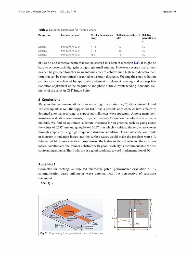
Appendix 1Geometry for rectangular edge-fed microstrip patch (performance evaluation of 5G communication-based millimeter wave antenna with the perspective of substrate thickness).
See Fig. 7.
Table 2 Designed parameters for multiple arrays
Design no Frequency band No of antenna in an array
Reflection coefficient (dB)
Relative permittivity εr
Design 1 Mm band 45 GHz 4 × 1 − 37 2.2
Design 2 Mm band 45 GHz 8 × 1 − 18 2.2
Design 3 Mm band 45 GHz 16 × 1 − 6 2.2
Fig. 7. 3D geometry for edge-fed microstrip patch antenna

Page 9 of 10Shakir et al. J Wireless Com Network (2021) 2021:179
AbbreviationsEIRP: Effective isotropic radiated power; FCC: Federal Communications Commission; HFSS: High-frequency structure simulator; ITU: International Telecommunication Union; MIMO: Multiple-input multiple-output; RPE: Radiation pattern envelope; SOI: Signal of interest.
AcknowledgementsThe authors would like to acknowledge support of Superior University Lahore for supporting throughout the research process.
Authors’ contributionsMS was responsible for overall implementation of the work. MA contributed in the findings and preparation of the manuscript, and SA has worked on research design, working of antennas. US formulated the problem, and Rafay has evaluated the parameters-based results. All authors read and approved the final manuscript.
FundingThe project is supported by our department.
Availability of data and materialsNot applicable.
Declarations
Competing interestsThe authors declare that they have no competing interest and hence policy of the journal followed for required processing.
Author details1 Department of Electrical Engineering, Superior University, Lahore 54000, Pakistan. 2 Department of Electrical Engineer-ing, University of Management and Technology, Lahore 54000, Pakistan.
Received: 8 March 2021 Accepted: 13 September 2021
References 1. Elain E. Analysis on the impact of product quality, price, brand image and brand loyalty towards samsung smart-
phone purchase intention in millennials. Dissertation. Universitas Pelita Harapan; 2021. 2. W. Ali, S. Das, H. Medkour, S. Lakrit, Planar dual-band 27/39 GHz millimeter-wave MIMO antenna for 5G applications.
Microsyst Technol 27(1), 283–292 (2021) 3. Yang Z, Jianjun L, Faqiri H, Shafik W, Talal Abdulrahman A, Yusuf M, Sharawy AM. Green internet of things and big
data application in smart cities development. Complexity 2021 (2021). 4. R. Przesmycki, M. Bugaj, L. Nowosielski, Broadband microstrip antenna for 5G wireless systems operating at 28 GHz.
Electronics 10(1), 1 (2021) 5. Teubner LK, Henkel J, Bekkers R. Industry consortia in mobile telecommunications standards setting: purpose,
organization and diversity. Telecommun Policy 45(3): 102059 (2021). 6. D. Cimini et al., Applicability of the Langley method for non-geostationary in-orbit satellite effective isotropic radi-
ated power estimation. IEEE Trans Antennas Propag 1, 9 (2021) 7. ETSI EN 302 217–4 V2.1 (2017–05) Fixed Radio Systems; Characteristics and requirements for point-to-point equip-
ment and antennas; Part 4: Antennas; 2017. 8. A.E. Keskin, Digitalization of memories–an analysis relationship between autobiographical memory and digital
photography. Media Lit Acad Res 3(1), 85–96 (2020) 9. S.K. Sharma et al., Toward tactile internet in beyond 5G era: recent advances. Current issues, and future directions.
IEEE Access 8, 56948–56991 (2020) 10. S. Sun, T.S. Rappaport, M. Shafi, P. Tang, J. Zhang, P.J. Smith, Propagation models and performance evaluation for 5G
millimeter-wave bands. IEEE Trans Veh Technol 67(9), 8422–8439 (2018) 11. Juneja S, Sharma R. Study of techniques to improve performance of patch antennas for 5G applications at millim-
eter wave (mmW) frequencies. IOP Conf Ser Mater Sci Eng 1022(1):012033; 2021. 12. T. Hong, S. Zheng, R. Liu, W. Zhao, Design of mm wave directional antenna for enhanced 5G broadcasting coverage.
Sensors 21(3), 746 (2021) 13. Lazarev V, Fokin G. Beamforming and spatial multiplexing performance evaluation in 5G ultra-dense networks. In:
International youth conference on electronics, telecommunications and information technologies. Cham: Springer; 2021.
14. Zhang J, Ge X, Li Q, Guizani M, Zhang Y. 5G millimeter-wave antenna array: design and challenges. IEEE Wirel Com-mun 24(2):106–112
15. M.V. Berry, Z.V. Lewis, J.F. Nye, On the Weierstrass-Mandelbrot fractal function. Proc R Soc Lond A Math Phys Sci 370(1743), 459–484 (1980)
16. E. Guariglia, Entropy and fractal antennas. Entropy 18(3), 84 (2016) 17. Guido RC, Barbon S, Vieira LS, Sanchez FL, Maciel CD, Pereira JC, Scalassara PR, Fonseca ES. Introduction to the
discrete shapelet transform and a new paradigm: joint time- frequency-shape analysis. In: IEEE international sympo-sium on circuits and systems (ISCAS). IEEE; 2008. p. 2893–2896

Page 10 of 10Shakir et al. J Wireless Com Network (2021) 2021:179
18. Guariglia E, Silvestrov S. Fractional-wavelet analysis of positive definite distributions and wavelets on $$ \varvec{\mathscr{D’}}(\mathbb{C}) $$. In: Engineering mathematics II. Cham: Springer; 2016. p. 337–53
19. K.C. Hwang, A modified Sierpinski fractal antenna for multiband application. IEEE Antennas Wirel Propag Lett 6, 357–360 (2007)
20. D. Mungur, S. Duraikannan, Microstrip patch antenna at 28 GHz for 5G applications. J Sci Technol Eng Manag Adv Res Innov 1, 5–7 (2018)
21. N.M. Nor, M.H. Jamaluddin, M.R. Kamarudin, M. Khalily, Rectangular dielectric resonator antenna array for 28 GHz applications. Prog Electromagn Res C 63, 53–61 (2016)
Publisher’s NoteSpringer Nature remains neutral with regard to jurisdictional claims in published maps and institutional affiliations.