
Performance Curve – EJECTOR 101...
22
Conditions of Service: GPM: ________ TDH: _______ Section EJECTOR Page 101 May © 2016 Pentair plc Performance Curve – S3S/S3SD/SB3S/SB3SD RPM: 1750 DISCHARGE: 3" SOLIDS: 2-1/2" The curves reflect maximum performance characteristics without exceeding full load (Nameplate) horsepower. All pumps have a service factor of 1.2. Operation is recommended in the bounded area with operational point within the curve limit. Performance curves are based on actual tests with clear water at 70° F. and 1280 feet site elevation. U.S. GPM M /HR 3 25 HEAD (FEET) HEAD (METERS) 0 0 -25 75 125 175 225 275 325 375 10 20 30 40 50 60 70 80 30% 40% 45% 50% 55% 55% 50% 45% 3 BHP 2 BHP 5 10 15 20 25 0 10 20 30 40 50 60 70 80 90 5.69" DIA. 6.13" DIA. 5.88" DIA. 5.25" DIA. 4.75" DIA. 6.50" DIA.
Transcript of Performance Curve – EJECTOR 101...

Conditions of Service:
GPM: ________ TDH: _______
Section EJECTOR Page 101
May © 2016 Pentair plc
Performance Curve – S3S/S3SD/SB3S/SB3SDRPM: 1750 DISCHARGE: 3" SOLIDS: 2-1/2"
The curves reflect maximum performance characteristics without exceeding full load (Nameplate) horsepower. All pumps have a service factor of 1.2. Operation is recommended in the bounded area with operational point within the curve limit. Performance curves are based on actual tests with clear water at 70° F. and 1280 feet site elevation.
1750 RPM
U.S. GPM
M /HR3
25
CS3S-1750
HEAD
(FEE
T)
HEAD
(MET
ERS)
0 0
60 Hz
-25 75 125 175 225 275 325 375
10
20
30
40
50
60
70
80
30%40%
45%50%
55%
55%
50%
45%
3BHP2
BHP
5
10
15
20
25
0 10 20 30 40 50 60 70 80 90
5.69" DIA.
6.13" DIA.5.88" DIA.
5.25" DIA.
4.75" DIA.
6.50" DIA.

Conditions of Service:
GPM: ________ TDH: ______ May © 2016 Pentair plc
Performance Curve – S3SD/SB3SDRPM: 1150 DISCHARGE: 3" SOLIDS: 2-1/2"
Section EJECTOR Page 102
The curves reflect maximum performance characteristics without exceeding full load (Nameplate) horsepower. All pumps have a service factor of 1.2. Operation is recommended in the bounded area with operational point within the curve limit. Performance curves are based on actual tests with clear water at 70° F. and 1280 feet site elevation.
2
4
6
8
10
12
14
16
18
20
22
24
0
1
2
3
4
5
6
7
20 40 60 80 100 120 140 160 180 200 220 240 260 280
0 5 10 15 20 25 30 35 40 45 50 55
50%
55%
30%
40%
50%
55%
3/4 BHP
5.25"
4.75"
5.88"
5.69"
6.13"
6.50"
1 BHP
U.S. GPM
M /HR
HE
AD
S (M
ETE
RS
)
HE
AD
S (F
EE
T)
S3S/SB3S/S3SD/SB3SD.1150RPM.epsDate: 7/12/00

Conditions of Service:
GPM: ________ TDH: _______May © 2016 Pentair plc
Section EJECTOR Page 103
1750 RPM
U.S. GPM
M /HR3
0
CS4S-1750
HEAD (FEET)
HEAD (METERS)
0
60
100 200 300 400 500 600 700
10
20
30
40
50
60
70
80
6.06" DIA.
6.25" DIA.
6.50" DIA.
6.75" DIA.
7.13" DIA.
7.5" DIA.
0 25 50 75 100 125 150 175
30%40%
50%
55%
60%
60%
55%
50%
7.5BHP
5BHP
3BHP
7.38" DIA.
0
25
20
15
10
5
The curves reflect maximum performance characteristics without exceeding full load (Nameplate) horsepower. All pumps have a service factor of 1.2. Operation is recommended in the bounded area with operational point within the curve limit. Performance curves are based on actual tests with clear water at 70° F. and 1280 feet site elevation.
Performance Curve – S4S/S4SD/SB4S/SB4SDRPM: 1750 DISCHARGE: 4" SOLIDS: 3"

Conditions of Service:
GPM: ________ TDH: ______ May © 2016 Pentair plc
Performance Curve – S4SD/SB4SDRPM: 1150 DISCHARGE: 4" SOLIDS: 3"
Section EJECTOR Page 104
The curves reflect maximum performance characteristics without exceeding full load (Nameplate) horsepower. All pumps have a service factor of 1.2. Operation is recommended in the bounded area with operational point within the curve limit. Performance curves are based on actual tests with clear water at 70° F. and 1280 feet site elevation.
2
4
6
8
10
12
14
16
18
20
22
24
26
28
30
32
34
0
1
2
3
4
5
6
7
8
9
10
50 100 150 200 250 300 350 400 450U.S. GPM
0 10 20 30 40 50 60 70 80 90 100
M /HR
HE
AD
(M
ET
ER
S)
HE
AD
(F
EE
T)
30%
40%
50%
55%
60%
7.50"
7.38"
7.13"
6.75"
6.50"
6.25"
6.06"
BHP 1
BHP 2
S4S/SB4S/S4SD/SB4SD.1150RPM.epsDate: 7/12/00

Section EJECTOR Page 201
October © 2014 Pentair Ltd.
Dimensional Data – S3S
A B C D E F G H I S3S 20-5/8 10-1/2 13-3/8 4-3/8 8-1/4 5-5/8 4-7/8 13-3/8 5-1/8
A
B
F
G
I EC
H
D
3" 125# Flange
ALL DIMENSIONS IN INCHESNOTE: CASTING DIMENSIONS MAY VARY ± 1/8”
October © 2014 Pentair Ltd.
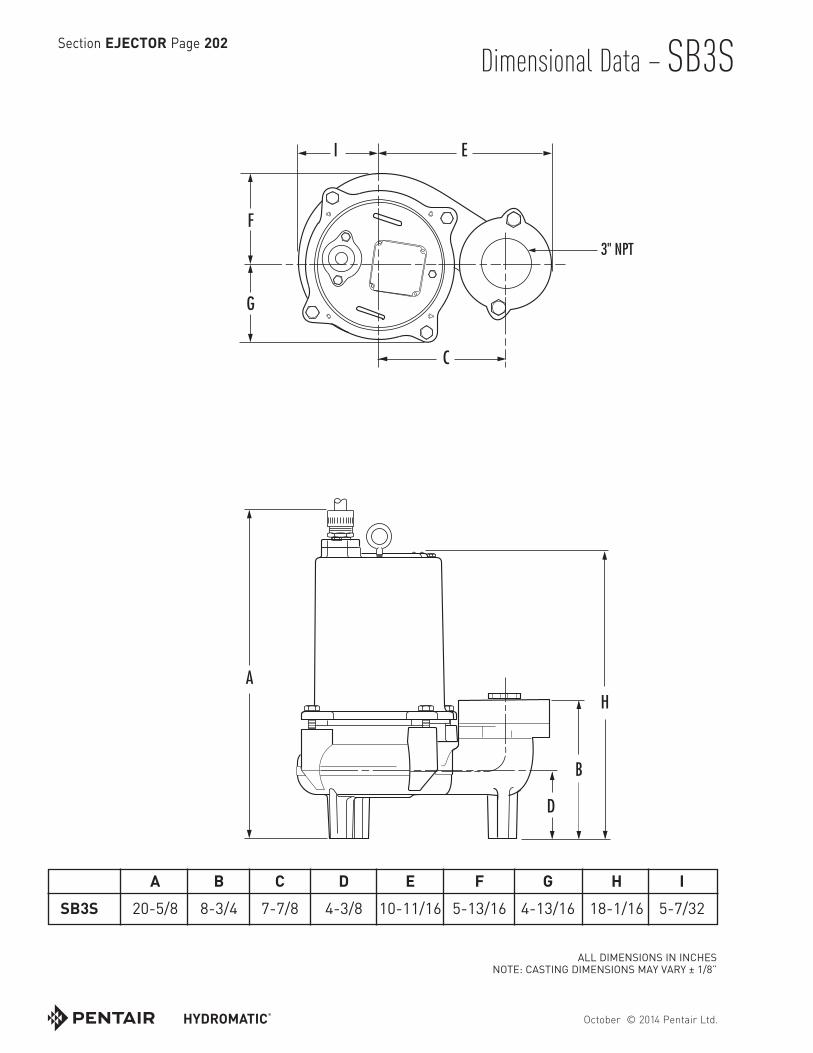
Dimensional Data – SB3SSection EJECTOR Page 202
A
F
G
C
H
D
B
EI
HE SSE DD SB3S ILU
3" NPT
A B C D E F G H I SB3S 20-5/8 8-3/4 7-7/8 4-3/8 10-11/16 5-13/16 4-13/16 18-1/16 5-7/32
ALL DIMENSIONS IN INCHESNOTE: CASTING DIMENSIONS MAY VARY ± 1/8”

October © 2014 Pentair Ltd.
Dimensional Data – S4S Section EJECTOR Page 203
I
D
A
G
F
B
E
C
H
4" 125# Flange
A B C D E F G H I S4S 23-1/8 12-3/4 16-3/8 6-1/2 10 7 5-3/4 13-5/8 6-3/8
ALL DIMENSIONS IN INCHESNOTE: CASTING DIMENSIONS MAY VARY ± 1/8”

October © 2014 Pentair Ltd.
Dimensional Data – SB4SSection EJECTOR Page 204
I
D
B
C
A
G
F
E
H
HE SSE DD SB4S ILU
4" NPT
A B C D E F G H I SB4S 23-1/8 11-3/8 8-5/16 6-1/2 11-1/8 7-1/16 5-13/16 20-3/16 6-1/2
ALL DIMENSIONS IN INCHESNOTE: CASTING DIMENSIONS MAY VARY ± 1/8”

October © 2014 Pentair Ltd.
Dimensional Data – S3SD Section EJECTOR Page 205
S3SD DIM.3/00
A H
D
B
F
G
I EC
3" 125# Flange
A B C D E F G H I S3SD 24-5/8 10-1/2 13-3/8 4-3/8 8-1/4 5-5/8 4-7/8 15-3/4 5-1/8
ALL DIMENSIONS IN INCHESNOTE: CASTING DIMENSIONS MAY VARY ± 1/8”

October © 2014 Pentair Ltd.
Dimensional Data – SB3SDSection EJECTOR Page 206
SB3SD DIM.3/00
F
G
C
EI
A
H
D
B
3" NPT
A B C D E F G H I SB3SD 26 8-1/2 7-3/4 4-3/8 10-5/8 5-13/16 4-13/16 20-1/2 5-7/32
ALL DIMENSIONS IN INCHESNOTE: CASTING DIMENSIONS MAY VARY ± 1/8”

October © 2014 Pentair Ltd.
Dimensional Data – S4SD Section EJECTOR Page 207
SB3SD DIM.3/00
AH
D
I
G
F
B
E
C
4" 125# Flange
A B C D E F G H I S4SD 27 12-3/4 16-3/8 6-1/2 10 7 5-3/4 15-3/4 6-3/8
ALL DIMENSIONS IN INCHESNOTE: CASTING DIMENSIONS MAY VARY ± 1/8”

October © 2014 Pentair Ltd.
Dimensional Data – SB4SDSection EJECTOR Page 208
I
G
F
E
SB4SD DIM.3/00
A
C
H
B
D
4" NPT
A B C D E F G H I SB4SD 29 11-1/4 8-9/32 6-5/8 11-1/8 7-1/8 5-15/16 23-1/2 6-1/2
ALL DIMENSIONS IN INCHESNOTE: CASTING DIMENSIONS MAY VARY ± 1/8”
Section EJECTOR Page 301
February © 2018 Pentair plc
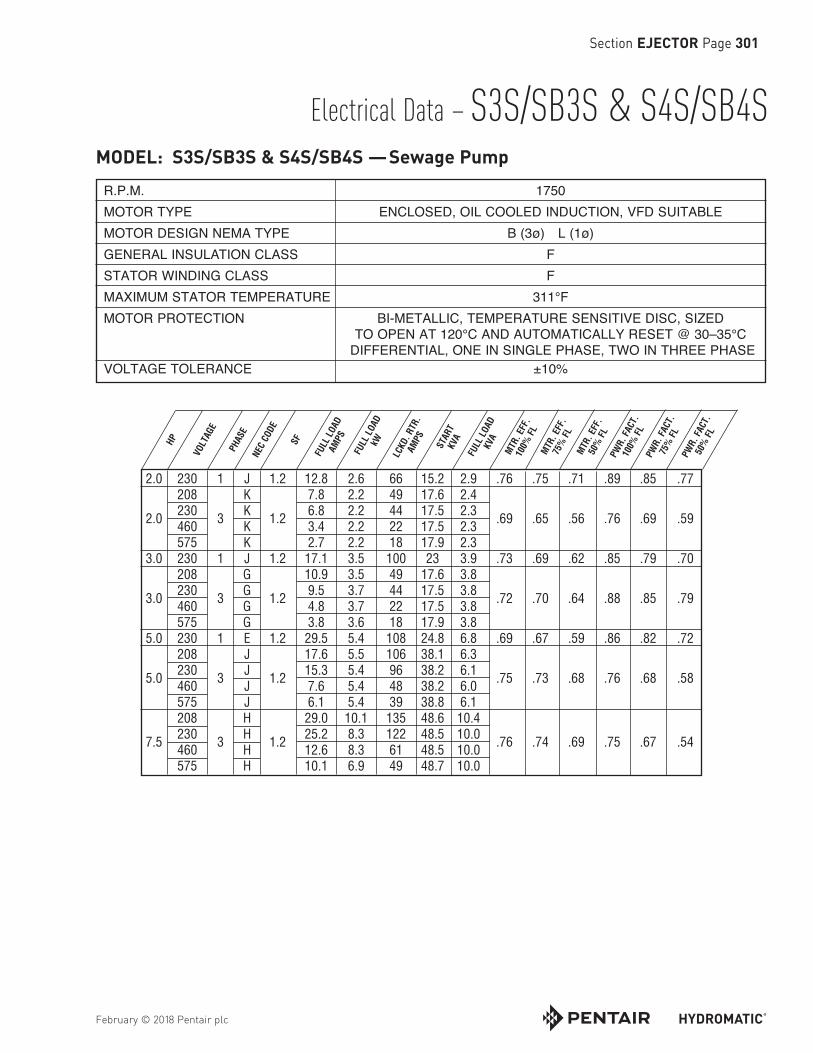
Electrical Data – S3S/SB3S & S4S/SB4S
R.P.M. 1750 MOTOR TYPE ENCLOSED, OIL COOLED INDUCTION, VFD SUITABLE MOTOR DESIGN NEMA TYPE B (3ø) L (1ø) GENERAL INSULATION CLASS F STATOR WINDING CLASS F MAXIMUM STATOR TEMPERATURE 311°F MOTOR PROTECTION BI-METALLIC, TEMPERATURE SENSITIVE DISC, SIZED TO OPEN AT 120°C AND AUTOMATICALLY RESET @ 30–35°C DIFFERENTIAL, ONE IN SINGLE PHASE, TWO IN THREE PHASE VOLTAGE TOLERANCE ±10%
2.0 230 1 J 1.2 12.8 2.6 66 15.2 2.9 .76 .75 .71 .89 .85 .77 208 K 7.8 2.2 49 17.6 2.4 2.0 230 3 K 1.2 6.8 2.2 44 17.5 2.3 .69 .65 .56 .76 .69 .59 460 K 3.4 2.2 22 17.5 2.3 575 K 2.7 2.2 18 17.9 2.3 3.0 230 1 J 1.2 17.1 3.5 100 23 3.9 .73 .69 .62 .85 .79 .70 208 G 10.9 3.5 49 17.6 3.8 3.0 230 3 G 1.2 9.5 3.7 44 17.5 3.8 .72 .70 .64 .88 .85 .79 460 G 4.8 3.7 22 17.5 3.8 575 G 3.8 3.6 18 17.9 3.8 5.0 230 1 E 1.2 29.5 5.4 108 24.8 6.8 .69 .67 .59 .86 .82 .72 208 J 17.6 5.5 106 38.1 6.3 5.0 230 3 J 1.2 15.3 5.4 96 38.2 6.1 .75 .73 .68 .76 .68 .58 460 J 7.6 5.4 48 38.2 6.0 575 J 6.1 5.4 39 38.8 6.1 208 H 29.0 10.1 135 48.6 10.4 7.5 230 3 H 1.2 25.2 8.3 122 48.5 10.0 .76 .74 .69 .75 .67 .54 460 H 12.6 8.3 61 48.5 10.0 575 H 10.1 6.9 49 48.7 10.0
MODEL: S3S/SB3S & S4S/SB4S —Sewage PumpHP
VOLT
AGE
PHAS
ENE
C CO
DE
SF
FULL
LOA
DAM
PS
FULL
LOA
DkW ST
ART
KVA
FULL
LOA
DKV
A
LCKD
. RTR
.AM
PS
MTR
. EFF
.10
0% F
LM
TR. E
FF.
75%
FL
MTR
. EFF
.50
% F
LPW
R. F
ACT.
100%
FL
PWR.
FAC
T.75
% F
LPW
R. F
ACT.
50%
FL
February © 2018 Pentair plc
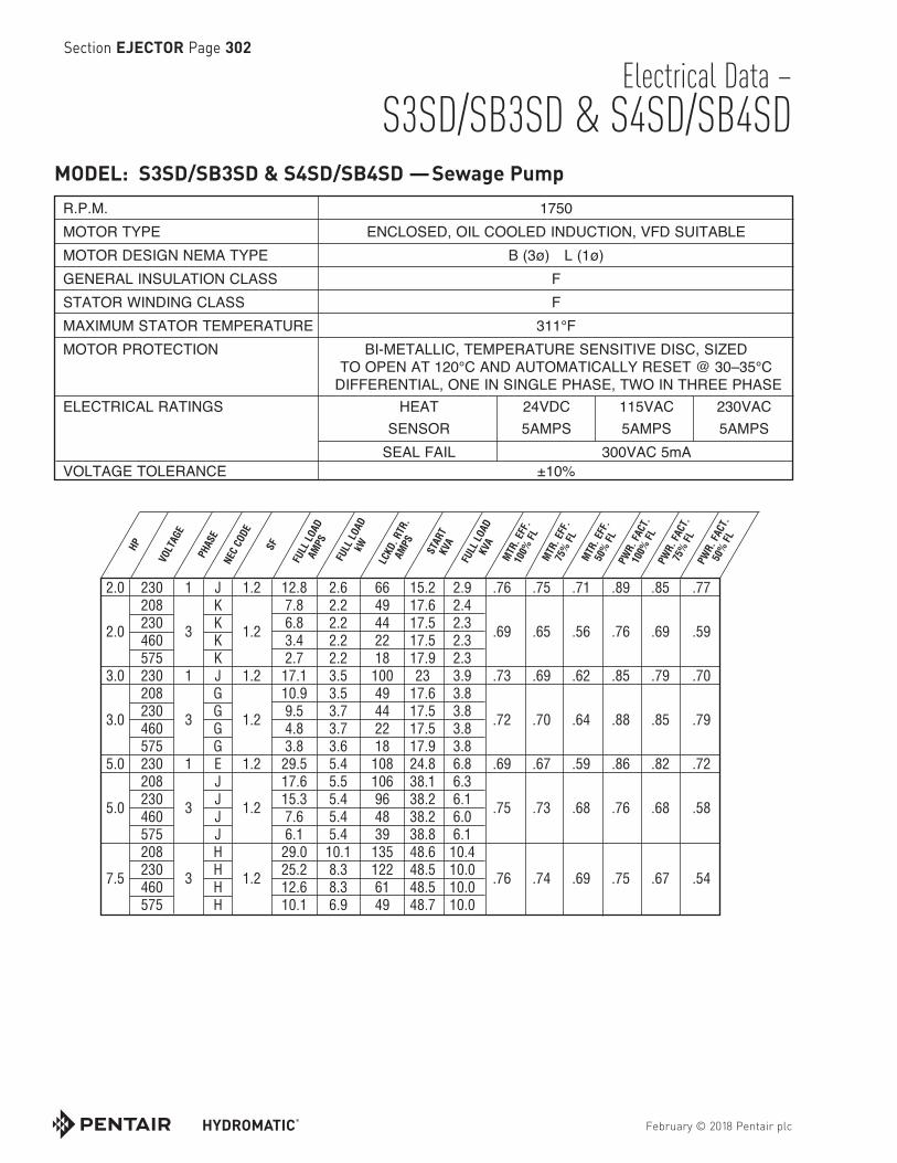
Electrical Data – S3SD/SB3SD & S4SD/SB4SD
Section EJECTOR Page 302
R.P.M. 1750 MOTOR TYPE ENCLOSED, OIL COOLED INDUCTION, VFD SUITABLE MOTOR DESIGN NEMA TYPE B (3ø) L (1ø) GENERAL INSULATION CLASS F STATOR WINDING CLASS F MAXIMUM STATOR TEMPERATURE 311°F MOTOR PROTECTION BI-METALLIC, TEMPERATURE SENSITIVE DISC, SIZED TO OPEN AT 120°C AND AUTOMATICALLY RESET @ 30–35°C DIFFERENTIAL, ONE IN SINGLE PHASE, TWO IN THREE PHASE ELECTRICAL RATINGS HEAT 24VDC 115VAC 230VAC SENSOR 5AMPS 5AMPS 5AMPS SEAL FAIL 300VAC 5mA VOLTAGE TOLERANCE ±10%
MODEL: S3SD/SB3SD & S4SD/SB4SD —Sewage Pump
2.0 230 1 J 1.2 12.8 2.6 66 15.2 2.9 .76 .75 .71 .89 .85 .77 208 K 7.8 2.2 49 17.6 2.4 2.0 230 3 K 1.2 6.8 2.2 44 17.5 2.3 .69 .65 .56 .76 .69 .59 460 K 3.4 2.2 22 17.5 2.3 575 K 2.7 2.2 18 17.9 2.3 3.0 230 1 J 1.2 17.1 3.5 100 23 3.9 .73 .69 .62 .85 .79 .70 208 G 10.9 3.5 49 17.6 3.8 3.0 230 3 G 1.2 9.5 3.7 44 17.5 3.8 .72 .70 .64 .88 .85 .79 460 G 4.8 3.7 22 17.5 3.8 575 G 3.8 3.6 18 17.9 3.8 5.0 230 1 E 1.2 29.5 5.4 108 24.8 6.8 .69 .67 .59 .86 .82 .72 208 J 17.6 5.5 106 38.1 6.3 5.0 230 3 J 1.2 15.3 5.4 96 38.2 6.1 .75 .73 .68 .76 .68 .58 460 J 7.6 5.4 48 38.2 6.0 575 J 6.1 5.4 39 38.8 6.1 208 H 29.0 10.1 135 48.6 10.4 7.5 230 3 H 1.2 25.2 8.3 122 48.5 10.0 .76 .74 .69 .75 .67 .54 460 H 12.6 8.3 61 48.5 10.0 575 H 10.1 6.9 49 48.7 10.0
HP
VOLT
AGE
PHAS
ENE
C CO
DE
SF
FULL
LOA
DAM
PS
FULL
LOA
DkW ST
ART
KVA
FULL
LOA
DKV
A
LCKD
. RTR
.AM
PS
MTR
. EFF
.10
0% F
LM
TR. E
FF.
75%
FL
MTR
. EFF
.50
% F
LPW
R. F
ACT.
100%
FL
PWR.
FAC
T.75
% F
LPW
R. F
ACT.
50%
FL

February © 2018 Pentair plc
Electrical Data – S3SD/SB3SD & S4SD/SB4SD
Section EJECTOR Page 303
1.0 208 1 N 1.2 9.4 10.2 54 1.0 11.2 1.9 .59 .57 .52 .43 .75 .70 .65 .54 230 L 8.2 8.9 42 1.3 9.7 208 L 4.3 5.0 27 9.7 1.0 230 3 L 1.2 3.8 4.3 23 1.1 9.2 1.5 .71 .70 .68 .61 .74 .71 .64 .54 460 K 1.9 2.2 11 8.8 575 H 1.5 1.7 7 7.0 2 208 1 K 1.2 18.6 20.6 82 2.6 17.1 3.9 .60 .59 .55 .47 .73 .68 .60 .50 230 K 17 17.9 71 16.3 208 J 8.4 9.6 43 2.4 15.5 2 230 3 K 1.2 7.3 8.3 42 2.2 16.7 2.9 .74 .74 .73 .67 .73 .70 .62 .52 460 K 3.6 4.2 21 2.2 16.7 575 K 2.9 3.3 17 2.2 16.9
MODEL: S3SD/SB3SD & S4SD/SB4SD —Sewage Pump
HP
VOLT
AGE
PHAS
ENE
C CO
DE
SF
FULL
LOA
DAM
PS SFAM
PS
LCKD
. RTR
.AM
PS
FULL
LOA
DKW ST
ART
KVA
FULL
LOA
DKV
A
MTR
. EFF
.@
SF
MTR
. EFF
.10
0% F
LM
TR. E
FF.
75%
FL
MTR
. EFF
.50
% F
LPW
R. F
ACT.
@ S
FPW
R. F
ACT.
100%
FL
PWR.
FAC
T.75
% F
LPW
R. F
ACT.
50%
FL
R.P.M. 1150 MOTOR TYPE ENCLOSED, OIL COOLED INDUCTION, VFD SUITABLE MOTOR DESIGN NEMA TYPE B (3ø) L (1ø) GENERAL INSULATION CLASS F STATOR WINDING CLASS F MAXIMUM STATOR TEMPERATURE 311°F MOTOR PROTECTION BI-METALLIC, TEMPERATURE SENSITIVE DISC, SIZED TO OPEN AT 120°C AND AUTOMATICALLY RESET @ 30–35°C DIFFERENTIAL, ONE IN SINGLE PHASE, TWO IN THREE PHASE ELECTRICAL RATINGS HEAT 24VDC 115VAC 230VAC SENSOR 5AMPS 5AMPS 5AMPS SEAL FAIL 300VAC 5mA VOLTAGE TOLERANCE ±10%

February © 2018 Pentair plc
Section EJECTOR Page 304
THIS PAGE INTENTIONALLY LEFT BLANK

Section EJECTOR Page 401
October © 2014 Pentair Ltd.
Technical Data – S3S/SB3S
MODEL: S3S/SB3S — Standard Single Seal Sewage Ejector PumpsPhysical Data: DISCHARGE SIZE 3” IMPELLER TYPE BALANCED, SEMI OPEN, 2 VANE CABLELENGTH 35’STANDARD
Liquid Handling: SOLIDS SIZE 2-1/2” MAXIMUM LIQUID 140ºF ACCEPTABLE LIQUID 6 - 9 SPECIFIC GRAVITY 0.9 - 1.1 VISCOSITY 28 - 35 SSU
Temperature: MAXIMUM STATOR 311°F OIL FLASH POINT 390°F HEAT SENSOR Open: 257°F MAX./239°F MIN. Closed: 194°F MAX./119°F MIN.
Technical Data: POWER CORD TYPE SOOW, W MOTOR HOUSING CAST IRON ASTM A-48 CLASS 30 CASING CAST IRON ASTM A-48 CLASS 30 IMPELLER DUCTILE IRON ASTM 536 MOTOR SHAFT 400 STAINLESS STEEL HARDWARE 300 SERIES STAINLESS STEEL “O” RINGS NITRILE MECHANICAL SEALS Standard: CARBON/CERAMIC/NITRILE, TYPE 21 UPPER BEARING (RADIAL) SINGLE ROW — BALL LOWER BEARING (THRUST) SINGLE ROW — BALL
MAT
ERIA
LS O
FC
ON
STR
UC
TIO
N

October © 2014 Pentair Ltd.
Section EJECTOR Page 402Technical Data – S4S/SB4S
MODEL: S4S/SB4S — Standard Single Seal Sewage Ejector Pumps
Physical Data: DISCHARGE SIZE 4” IMPELLER TYPE BALANCED, SEMI OPEN, 2 VANE CABLELENGTH 35’STANDARD 50’OPTIONAL
Liquid Handling: SOLIDS SIZE 3”
MAXIMUM LIQUID 140ºF
ACCEPTABLE PH RANGE 6 - 9
SPECIFIC GRAVITY 0.9 - 1.1
VISCOSITY 28 - 35 SSU
Temperature: MAXIMUM STATOR 311°F OIL FLASH POINT 390°F HEAT SENSOR Open: 257°F MAX./239°F MIN. Closed: 194°F MAX./119°F MIN.
Technical Data: POWER CORD TYPE SOOW, W MOTOR HOUSING CAST IRON ASTM A-48 CLASS 30 CASING CAST IRON ASTM A-48 CLASS 30 IMPELLER DUCTILE IRON ASTM 536 MOTOR SHAFT 400 STAINLESS STEEL HARDWARE 300 SERIES STAINLESS STEEL “O” RINGS NITRILE MECHANICAL SEALS Standard: CARBON/CERAMIC/NITRILE, TYPE 21 UPPER BEARING (RADIAL) SINGLE ROW — BALL LOWER BEARING (THRUST) SINGLE ROW — BALL
MAT
ERIA
LS O
FC
ON
STR
UC
TIO
N
October © 2014 Pentair Ltd.
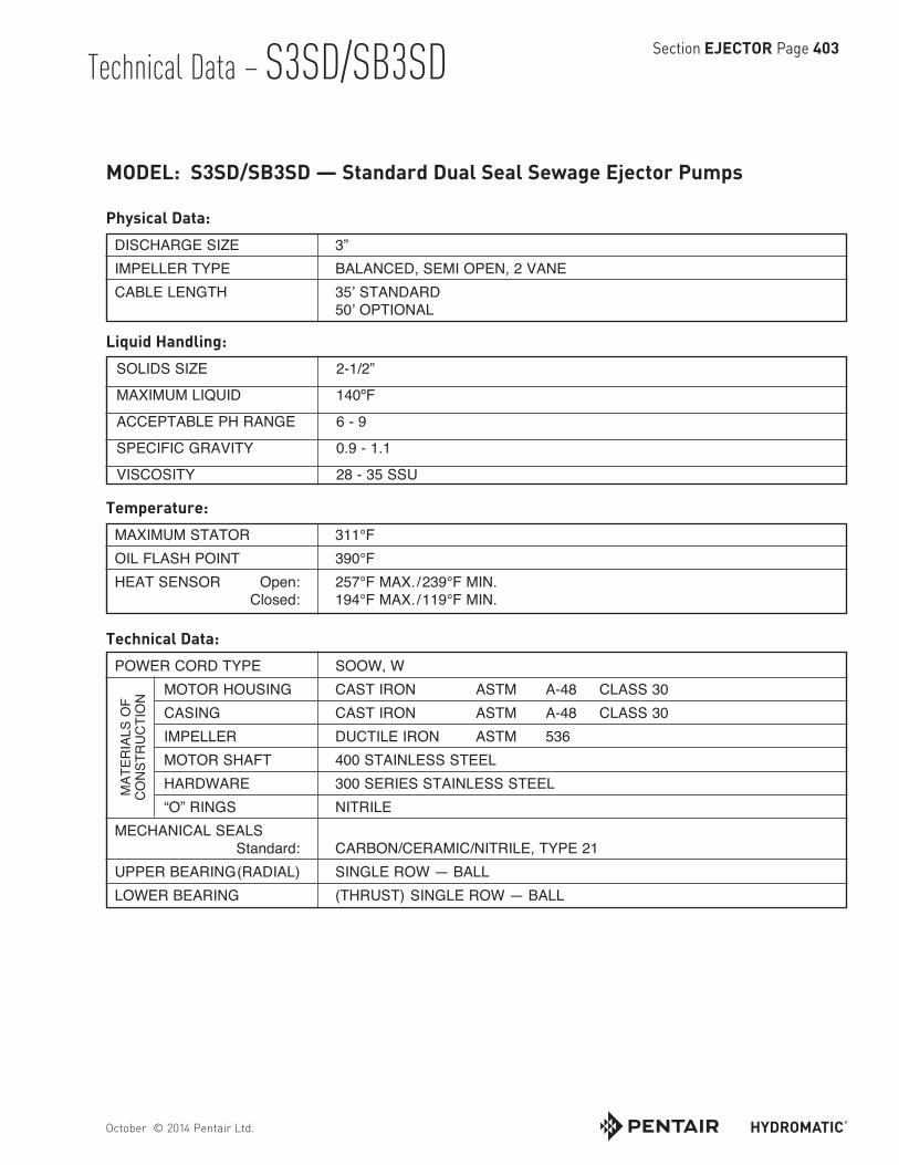
Section EJECTOR Page 403 Technical Data – S3SD/SB3SD
MODEL: S3SD/SB3SD — Standard Dual Seal Sewage Ejector Pumps
Physical Data: DISCHARGE SIZE 3” IMPELLER TYPE BALANCED, SEMI OPEN, 2 VANE CABLELENGTH 35’STANDARD 50’OPTIONAL
Liquid Handling: SOLIDS SIZE 2-1/2”
MAXIMUM LIQUID 140ºF
ACCEPTABLE PH RANGE 6 - 9
SPECIFIC GRAVITY 0.9 - 1.1
VISCOSITY 28 - 35 SSU
Temperature: MAXIMUM STATOR 311°F OIL FLASH POINT 390°F HEAT SENSOR Open: 257°F MAX./239°F MIN. Closed: 194°F MAX./119°F MIN.
Technical Data: POWER CORD TYPE SOOW, W MOTOR HOUSING CAST IRON ASTM A-48 CLASS 30 CASING CAST IRON ASTM A-48 CLASS 30 IMPELLER DUCTILE IRON ASTM 536 MOTOR SHAFT 400 STAINLESS STEEL HARDWARE 300 SERIES STAINLESS STEEL “O” RINGS NITRILE MECHANICAL SEALS Standard: CARBON/CERAMIC/NITRILE, TYPE 21 UPPER BEARING (RADIAL) SINGLE ROW — BALL LOWER BEARING (THRUST) SINGLE ROW — BALL
MAT
ERIA
LS O
FC
ON
STR
UC
TIO
N

October © 2014 Pentair Ltd.
Section EJECTOR Page 404Technical Data – S4SD/SB4SD
MODEL: S4SD/SB4SD — Standard Dual Seal Sewage Ejector Pumps
Physical Data: DISCHARGE SIZE 4” IMPELLER TYPE BALANCED, SEMI OPEN, 2 VANE CABLELENGTH 35’STANDARD
Liquid Handling: SOLIDS SIZE 3”
MAXIMUM LIQUID 140ºF
ACCEPTABLE PH RANGE 6 - 9
SPECIFIC GRAVITY 0.9 - 1.1
VISCOSITY 28 - 35 SSU
Temperature: MAXIMUM STATOR 311°F OIL FLASH POINT 390°F HEAT SENSOR Open: 257°F MAX./239°F MIN. Closed: 194°F MAX./119°F MIN.
Technical Data: POWER CORD TYPE SOOW, W MOTOR HOUSING CAST IRON ASTM A-48 CLASS 30 CASING CAST IRON ASTM A-48 CLASS 30 IMPELLER DUCTILE IRON ASTM 536 MOTOR SHAFT 400 STAINLESS STEEL HARDWARE 300 SERIES STAINLESS STEEL “O” RINGS NITRILE MECHANICAL SEALS Standard: CARBON/CERAMIC/NITRILE, TYPE 21 UPPER BEARING (RADIAL) SINGLE ROW — BALL LOWER BEARING (THRUST) SINGLE ROW — BALL
MAT
ERIA
LS O
FC
ON
STR
UC
TIO
N

Specifications – Ejector Section EJECTOR Page 501
October © 2017 Pentair plc
3" & 4" SUBMERSIBLE SEWAGE PUMPS
GENERAL Furnish all labor, materials, equipment and incidentals required to provide _______ (qty.) solids handling submersible centrifugal sewage pumps(s) as specified herein.
OPERATING CONDITIONS Each pump shall be rated ______ HP, _____ volts, _____ phase, _____ hertz, and _____ RPM. The unit shall produce _________ U.S. GPM at ________ feet TDH. The S3S shall be capable of handling a 2-1/2" spherical solid and the S4S a 3" spherical solid. The pump shall be non-overloading throughout the entire range of operation without employing service factor. The pump shall reserve a minimum service factor of 1.20. The performance curve submitted for approval shall state in addition to head and capacity performance, the pump efficiency and solid handling capability.
CONSTRUCTION Each pump shall be of the sealed submersible type, Models S3S, S4S, SB3S, SB4S, S3SD, S4SD, SB3SD, and SB4SD as manufactured by Hydromatic Pump. The pump volute, motor and seal housing shall be high quality gray cast iron, ASTM A-48, Class 30. The pump discharge shall be fitted with a 3" standard ASA 125 lb. flange, faced and drilled for the S3S models, and a 4" standard ASA 125 lb. flange, faced and drilled for the S4S models. All external mating parts shall be machined and Nitrile O-ring sealed on a beveled edge. Gaskets shall not be acceptable. All fasteners exposed to the pumped liquids shall be 300 series stainless steel.
ELECTRICAL POWER CORD Electrical power cord shall be SOOW or W, water resistant 600V, 90ºC, UL and CSA approved and applied dependent on amp draw for size.
The pump shall be double protected with compression fitting and an epoxy potted area at the power cord entry to the pump.
The power cable entry into the cord cap assembly shall first be made with a compression fitting. Each individual lead shall be stripped down to the bare wire, at staggered intervals, and each strand shall be individually separated. This area of the cord cap shall then be filled with an epoxy compound potting which will prevent water contamination to gain entry even in the event of wicking or capillary attraction.
The power cord assembly shall then be connected to the motor leads with insulated butt connectors rather than a terminal board that allows for possible leaks.
The cord cap assembly where bolted to the motor housing shall be sealed with a Nitrile O-ring on a beveled edge to assure proper sealing.
MOTOR The stator, rotor and bearings shall be mounted in a sealed submersible type housing. The stator windings shall have Class F insulation (155ºC or 311ºF) and dielectric oil-filled motor, NEMA B design. Single-phase motors shall have thermal type overload protection with automatic reset and be capacitor start with capacitor located in the control panel. Three phase motors shall use magnetic starters with overload relays located in the control panel for further protection. Because air-filled motors do not dissipate heat as efficiently as oil-filled motors, air-filled designs shall not be acceptable.
Stators shall be securely held in place with threaded fasteners so they may be easily removed in the field. No special tools shall be required for pump and motor disassembly.

Section EJECTOR Page 502
October © 2017 Pentair plc
BEARINGS AND SHAFT An upper radial bearing and lower thrust bearing shall be required. Both the upper radial bearing and the lower thrust bearing shall be heavy-duty single row ball bearings that are permanently lubricated by the dielectric oil that fills the motor housing. Double row, sealed grease packed bearings shall not be acceptable. Bearings that require lubrication according to a prescribed schedule shall not be acceptable.
The shaft shall be machined from a solid 400 stainless steel and be a design that is of larger diameter with minimum overhand to reduce shaft deflection and prolong bearing life.
SEALS The S3S, S4S, SB3S, and SB4S shall have a mechanical single seal, Type 21. The S3SD, S4SD, SB3SD, and SB4SD shall have a mechanical dual seal, Type 21. The seal shall be used with the rotating seal face being carbon and the stationary seal face to be ceramic. The seal shall be replaceable without disassembly of the seal plate and without the use of special tools. Pump-out vanes shall be present on the backside of the impeller to keep contaminants out of the seal area. Units that require the use of tungsten-carbide seals or foreign manufactured seals shall not be acceptable.
IMPELLER Impeller shall be of the two-vane, semi-enclosed design and have pump-out vanes on the backside of the impeller to prevent grit and other materials from collecting in the seal area. Single vane design impellers that cannot be easily trimmed and that do not maintain balance with wear, causing shaft defections and reducing seal and bearing life, are not acceptable. Impeller shall not require coating. Because most impeller coatings do not remain beyond the very early life of the impeller, efficiency and other performance data submitted shall be based on performance with an uncoated impeller. Attempts to improve efficiency by coating impeller shall not be acceptable.
Impellers shall be dynamically balanced. The tolerance values shall be as listed below according to the International Standard Organization grade 6.3 for rotors in rigid frames.
RPM Tolerance 1750 .02 in. – oz./lb. of impeller weight
The impeller shall be slip fit to the shaft and key driven. A 400 series stainless steel washer and impeller bolt shall be used to fasten the impeller to the shaft. Threaded shafts for attachment of the impeller shall not be acceptable.
CASING The casing shall be of the end suction volute type having sufficient strength and thickness to withstand all stress and strain from service at full operating pressure and load. The casing shall be of the centerline discharge type equipped with an automatic pipe coupling arrangement for ease of installation and piping alignment. The design shall be such that the pumps will be automatically connected to the discharge piping when lowered into position with the guide rails. The casing shall be accurately machined and bored for register fits with the suction and casing covers.