Performance and Radiation Damage of the ATLAS ...
35
Performance and Radiation D amage of the ATLAS Semiconductor T racker during LHC Run 2 26 December 2019, KEK seminar Shigeki Hirose (Uni - Freiburg)
Transcript of Performance and Radiation Damage of the ATLAS ...
Performance and Radiation Damage
of the ATLAS Semiconductor Tracker
during LHC Run 2
26 December 2019, KEK seminar
Shigeki Hirose (Uni-Freiburg)
■ ATLAS Experiment
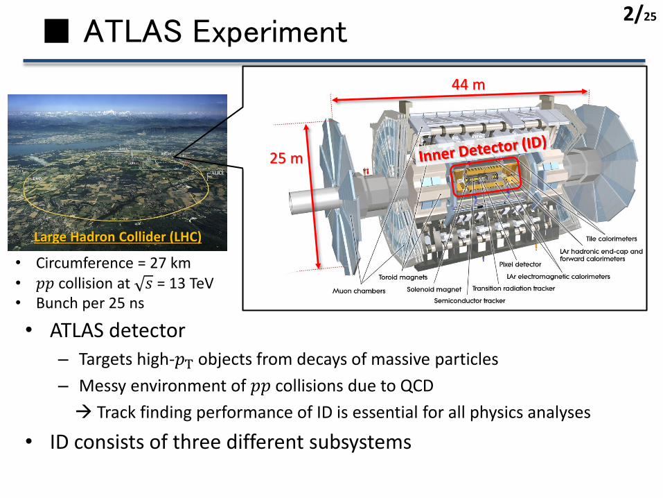
• ATLAS detector– Targets high-𝑝T objects from decays of massive particles
– Messy environment of 𝑝𝑝 collisions due to QCD
→ Track finding performance of ID is essential for all physics analyses
• ID consists of three different subsystems
Large Hadron Collider (LHC)
• Circumference = 27 km• 𝑝𝑝 collision at 𝑠 = 13 TeV• Bunch per 25 ns
25 m
44 m
2/25

■ SemiConductor Tracker (SCT)
6x2 on-detector chips
double-sided
ATLASTrigger System trigger
768 strips on each sideBarrel module
Formatted
2 x data transmission line
SCT (endcap)
SCT (barrel)
S-link
• 4 layers (barrel) and 9×2 disks (endcaps)
• > 6M channels– Maintaining a stable system is
important
6 cm
3/25

■ Silicon Sensor
• 𝑝+-on-𝑛 type sensor– Depletion zone grows from 𝑝+ side
– Full-depletion voltage 𝑉FD = 65 V without irradiation
• Type-inversion around 1013 1-MeV 𝑛-eq/cm2
– Full depletion is necessary to keep good performance
p+ strip
n+ electrode
n- bulk
p- bulk
typeinv.
Depletion zone
Innermost barrel
4/25
■ LHC Run 2: 2015-2018
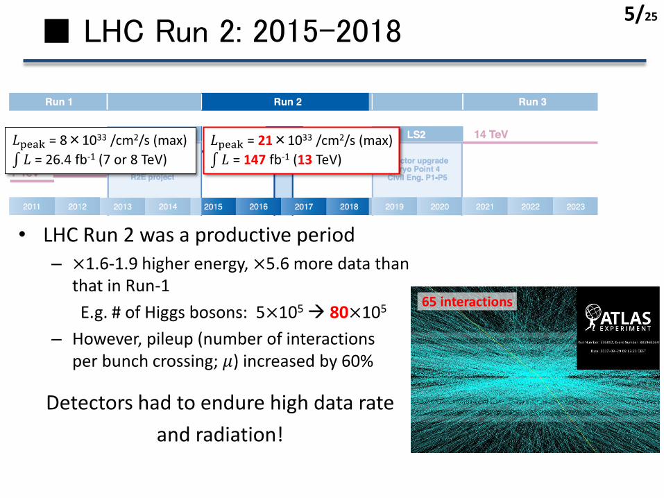
• LHC Run 2 was a productive period
– ×1.6-1.9 higher energy, ×5.6 more data than that in Run-1
E.g. # of Higgs bosons: 5×10⁵→ 80×105
– However, pileup (number of interactions per bunch crossing; 𝜇) increased by 60%
Detectors had to endure high data rate
and radiation!
𝐿peak = 8×1033 /cm2/s (max)
𝐿 = 26.4 fb-1 (7 or 8 TeV)
𝐿peak = 21×1033 /cm2/s (max)
𝐿 = 147 fb-1 (13 TeV)
65 interactions
5/25
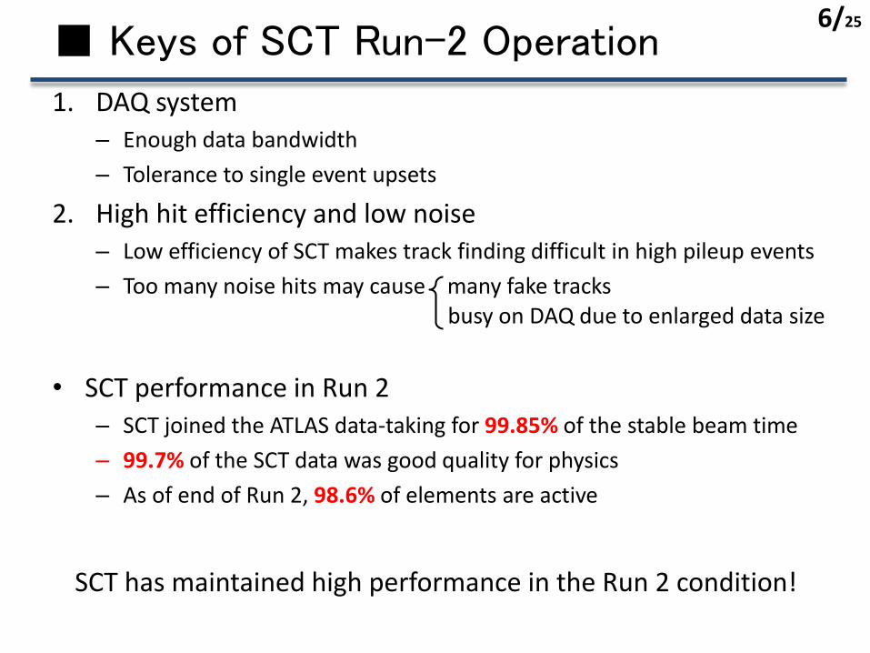
■ Keys of SCT Run-2 Operation
1. DAQ system– Enough data bandwidth
– Tolerance to single event upsets
2. High hit efficiency and low noise– Low efficiency of SCT makes track finding difficult in high pileup events
– Too many noise hits may cause many fake tracks
• SCT performance in Run 2– SCT joined the ATLAS data-taking for 99.85% of the stable beam time
– 99.7% of the SCT data was good quality for physics
– As of end of Run 2, 98.6% of elements are active
SCT has maintained high performance in the Run 2 condition!
busy on DAQ due to enlarged data size
6/25
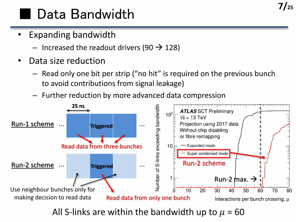
■ Data Bandwidth
• Expanding bandwidth– Increased the readout drivers (90 → 128)
• Data size reduction– Read only one bit per strip (“no hit” is required on the previous bunch
to avoid contributions from signal leakage)
– Further reduction by more advanced data compression
Run-1 scheme
Run-2 scheme
Use neighbour bunches only for making decision to read data
Triggered... ...
Read data from only one bunch
Read data from three bunches
... ...
25 ns
Triggered
Run-2 max. →
Run-2 scheme
All S-links are within the bandwidth up to 𝜇 = 60
7/25
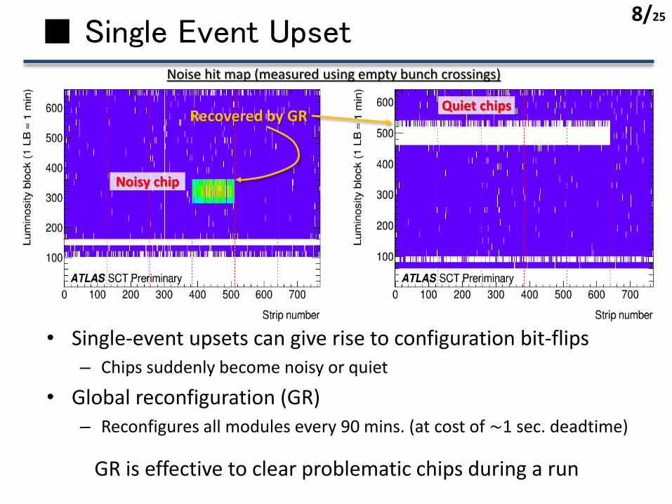
■ Single Event Upset
Noisy chip
Noise hit map (measured using empty bunch crossings)
Quiet chips
• Single-event upsets can give rise to configuration bit-flips– Chips suddenly become noisy or quiet
• Global reconfiguration (GR)– Reconfigures all modules every 90 mins. (at cost of ~1 sec. deadtime)
GR is effective to clear problematic chips during a run
Recovered by GR
8/25
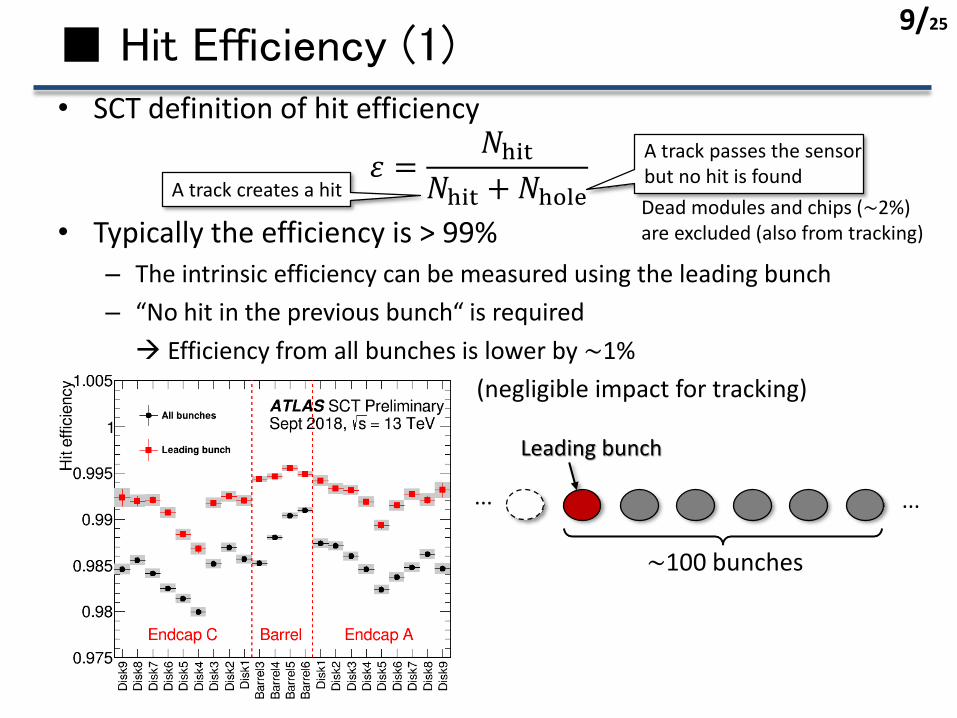
■ Hit Efficiency (1)• SCT definition of hit efficiency
𝜀 =𝑁hit
𝑁hit +𝑁hole• Typically the efficiency is > 99%
– The intrinsic efficiency can be measured using the leading bunch
– “No hit in the previous bunch“ is required
→ Efficiency from all bunches is lower by ~1%
(negligible impact for tracking)
Dead modules and chips (~2%) are excluded (also from tracking)
A track creates a hit
A track passes the sensor but no hit is found
Leading bunch
... ...
~100 bunches
9/25
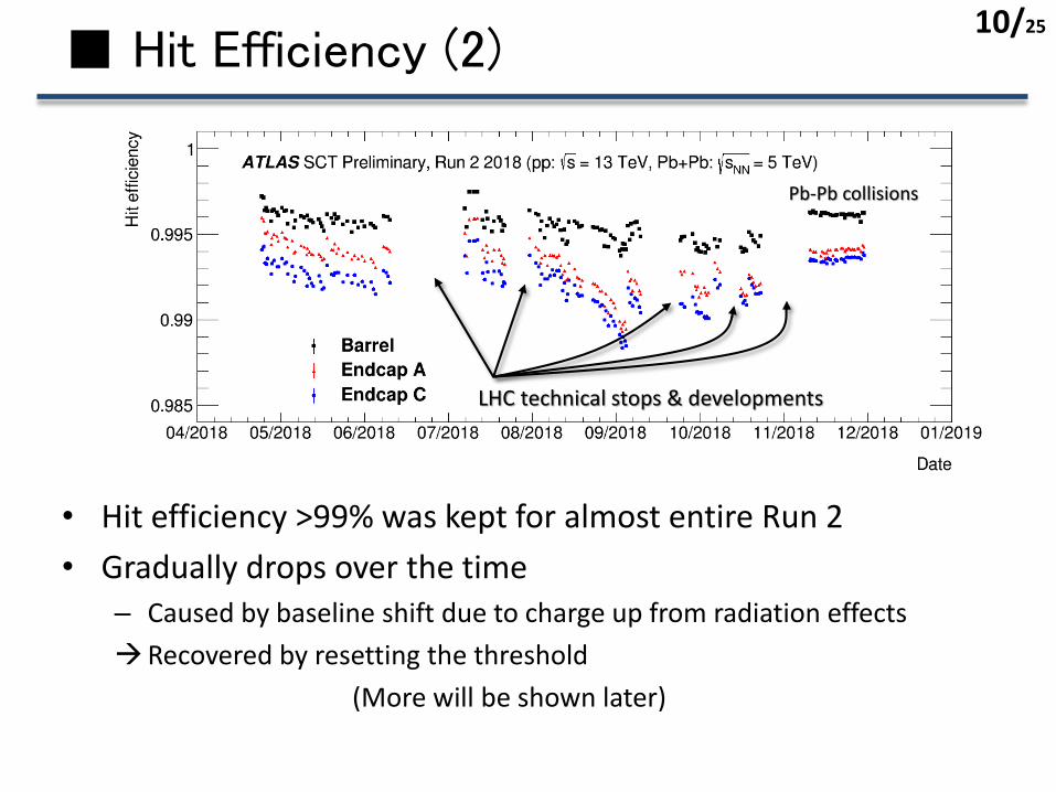
■ Hit Efficiency (2)
• Hit efficiency >99% was kept for almost entire Run 2
• Gradually drops over the time– Caused by baseline shift due to charge up from radiation effects
→Recovered by resetting the threshold
(More will be shown later)
LHC technical stops & developments
Pb-Pb collisions
10/25
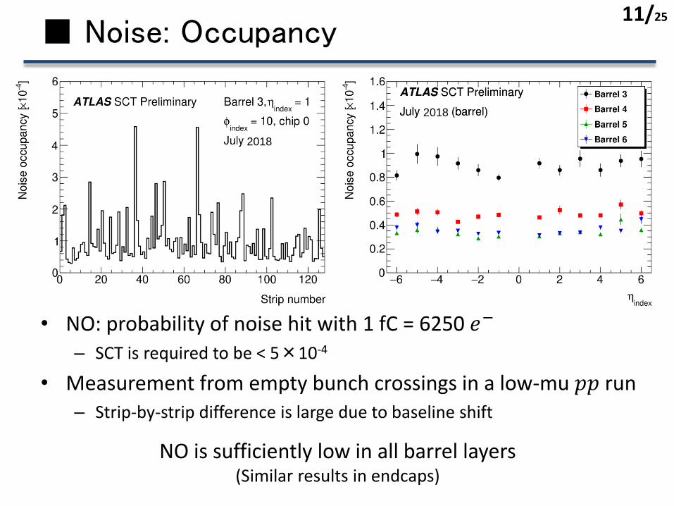
■ Noise: Occupancy
• NO: probability of noise hit with 1 fC = 6250 𝑒−
– SCT is required to be < 5×10⁻⁴
• Measurement from empty bunch crossings in a low-mu 𝑝𝑝 run– Strip-by-strip difference is large due to baseline shift
NO is sufficiently low in all barrel layers(Similar results in endcaps)
2018
2018
11/25

■ Noise: Threshold Scan A. Abdesselam et al., JINST 3 P01003 (2008)
• Noise can be estimated from threshold scan with a fixed input charge– Extract noise from 𝜎 of an error function
– More stable estimation→ Better for monitoring time dependence
• 1600~1800 𝑒− at the end of Run 2
Input = 1 fC
𝜎 = noise50% occ.
12/25

■ Noise: Time Evolution
• Noise increased by 10-15% during Run 2– Doesn’t impact data quality (NO was low enough)
• Somewhat unstable during the data-taking periods– Under investigation
LHC shutdown
13/25

■ Detector Calibration
Run 1 Run 2
Many noisy strips are recovered
Periodical calibration is essential to maintain performance!
• Electrical calibration is performed every ~1 month– Reset threshold etc.
– Disable too noisy elements
• E.g. number of noisy strips increases with accumulating radiation effects
→ Recovered by calibration
14/25
𝑟 (cm) 60
40
20
0
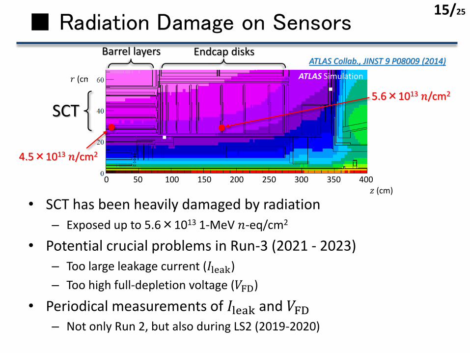
■ Radiation Damage on Sensors
• SCT has been heavily damaged by radiation
– Exposed up to 5.6×10¹³ 1-MeV 𝑛-eq/cm2
• Potential crucial problems in Run-3 (2021 - 2023)– Too large leakage current (𝐼leak)
– Too high full-depletion voltage (𝑉FD)
• Periodical measurements of 𝐼leak and 𝑉FD– Not only Run 2, but also during LS2 (2019-2020)
SCT
Endcap disks
5.6×10¹³ 𝑛/cm2
4.5×10¹³ 𝑛/cm2
Barrel layers
0 50 100 150 200 250 300 350 400𝑧 (cm)
ATLAS Collab., JINST 9 P08009 (2014)
15/25
ATLAS Simulation

■ Measurements during LS2
• Perform IV scan etc. every two months– 5-10 people staying at CERN contribute
Jan Feb Mar Apr May Jun Jul Aug Sep Oct Nov Dec
Nominal temperature~-17℃
~-7℃LS2 temperature
Room temp. (for ID endcap opening) SCT turned on
History of 2019
16/25
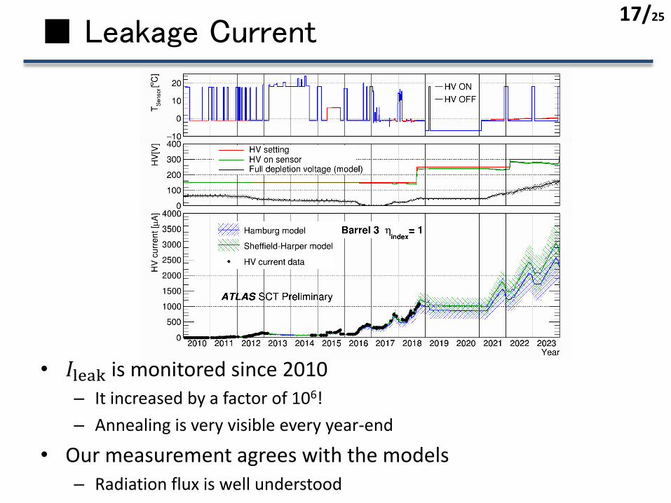
■ Leakage Current
• 𝐼leak is monitored since 2010– It increased by a factor of 106!
– Annealing is very visible every year-end
• Our measurement agrees with the models– Radiation flux is well understood
17/25

■ I-V Measurement
• Measure leakage current and noise vs HV– After reaching HV = 𝑉FD, leakage current and noise become plateau
– However the transition is not very sharp
• 𝑉FD estimation from the I-V measurement– Rough estimate is 50-100 V
𝑉FD?
High temperature
𝑉FD?
18/25
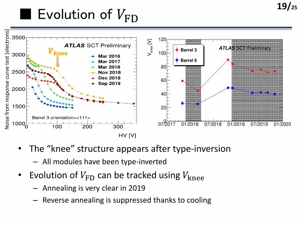
■ Evolution of 𝑉FD
• The “knee” structure appears after type-inversion– All modules have been type-inverted
• Evolution of 𝑉FD can be tracked using 𝑉knee– Annealing is very clear in 2019
– Reverse annealing is suppressed thanks to cooling
𝑽𝐤𝐧𝐞𝐞
19/25
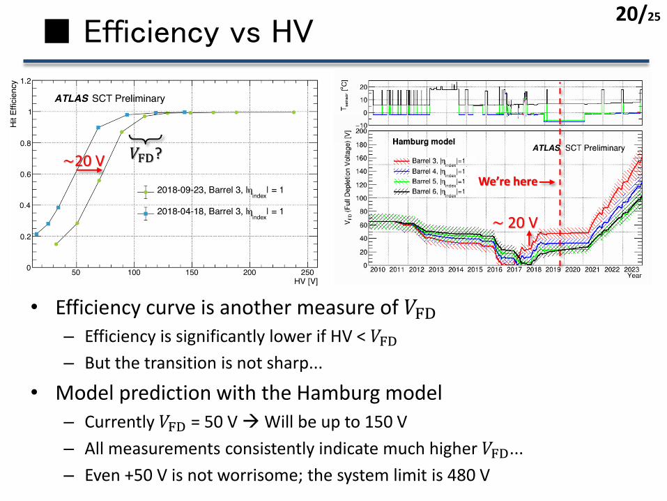
■ Efficiency vs HV
• Efficiency curve is another measure of 𝑉FD– Efficiency is significantly lower if HV < 𝑉FD– But the transition is not sharp...
• Model prediction with the Hamburg model
– Currently 𝑉FD = 50 V →Will be up to 150 V
– All measurements consistently indicate much higher 𝑉FD...
– Even +50 V is not worrisome; the system limit is 480 V
We’re here
~20 V
~ 20 V
𝑉FD?
20/25

■ Towards Run 3: 2021-2024
• Conditions will be similar to Run 2
• No major upgrade is planned for SCT– The very robust and stable system has been already established
because of a number of improvements
– Need a solid prediction for Run 3 operation
𝐿peak = 8×1033 /cm2/s (max)
𝐿 = 26.4 fb-1 (7 or 8 TeV)
𝐿peak = 21×1033 /cm2/s (max)
𝐿 = 147 fb-1 (13 TeV)
𝐿peak = 20×1033 /cm2/s (max)
𝐿 = 220-230 fb-1 (13 or 14 TeV)
Details: N. Karastathis’ report at Evian Workshop 2019
We’re here
2024
One-year extension was recently decided:https://home.cern/news/news/accelerators/new-schedule-lhc-and-its-successor
21/25
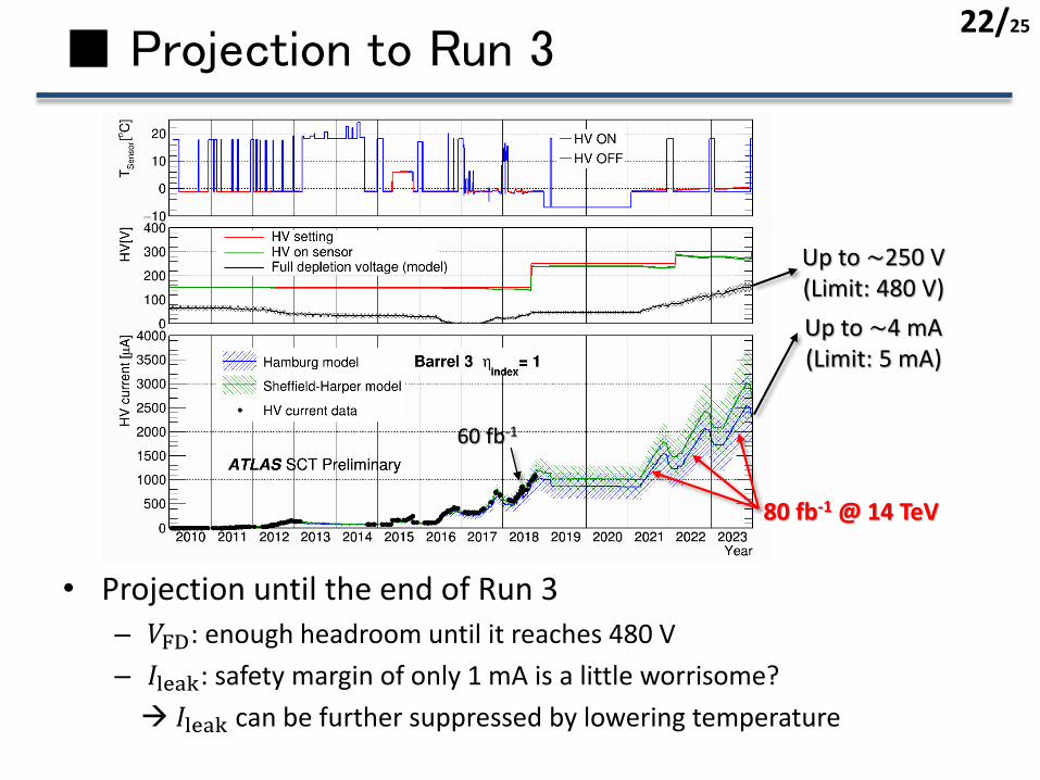
■ Projection to Run 3
• Projection until the end of Run 3– 𝑉FD: enough headroom until it reaches 480 V
– 𝐼leak: safety margin of only 1 mA is a little worrisome?
→ 𝐼leak can be further suppressed by lowering temperature
Up to ~250 V(Limit: 480 V)
Up to ~4 mA(Limit: 5 mA)
22/25
60 fb-1
80 fb-1 @ 14 TeV
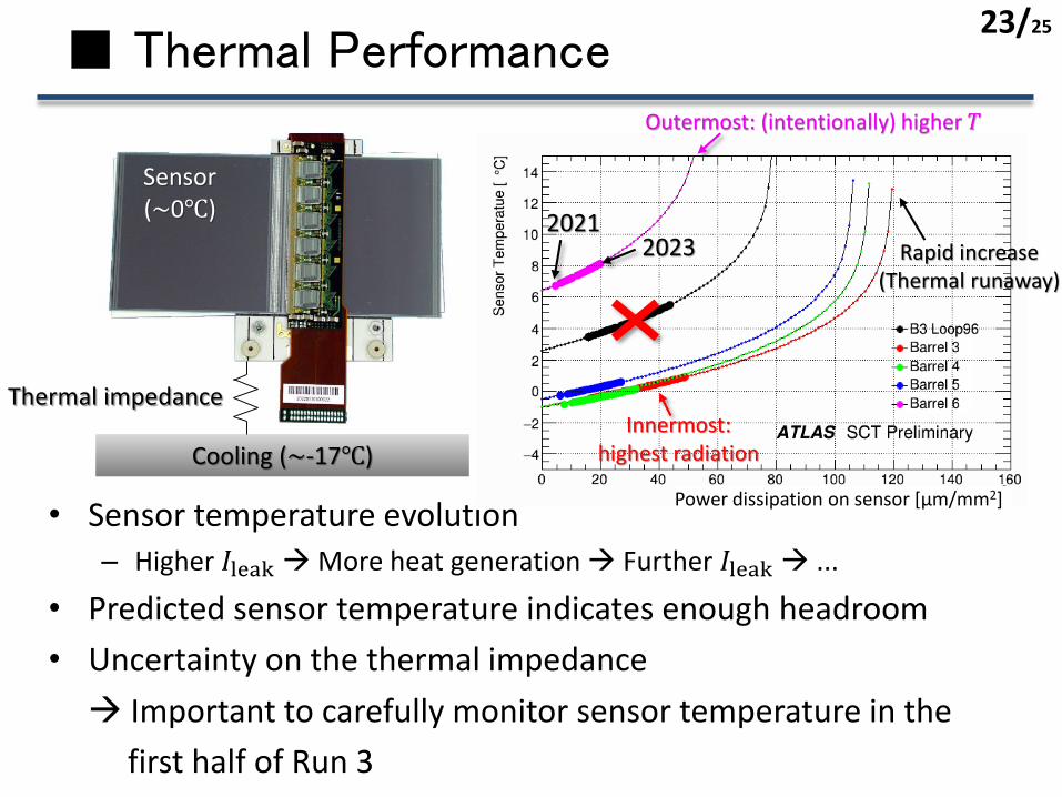
■ Thermal Performance
• Sensor temperature evolution
– Higher 𝐼leak→More heat generation → Further 𝐼leak→ ...
• Predicted sensor temperature indicates enough headroom
• Uncertainty on the thermal impedance
→ Important to carefully monitor sensor temperature in the
first half of Run 3
Outermost: (intentionally) higher 𝑇
Rapid increase(Thermal runaway)
Power dissipation on sensor [μm/mm2]
Innermost: highest radiation
20212023
Thermal impedance
Cooling (~-17℃)
Sensor(~0℃)
23/25

■ Preparation for DQ in Run 3
• Radiation damage will be more severe– Catch DQ degradation before it becomes intolerant
• Efficiency rapidly drops within ~1 month– However, it’s too slow to be caught by run-by-run comparisons
→Sophisticated monitoring & quick diagnosis tool is
being developed
(N.B. lower HV was intentionally applied to this module)
1.5 months
Efficiency recovered after HV was increased
24/25
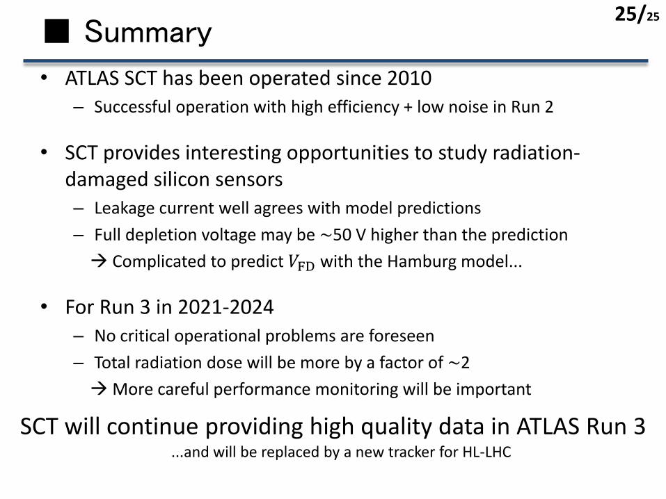
■ Summary
• ATLAS SCT has been operated since 2010– Successful operation with high efficiency + low noise in Run 2
• SCT provides interesting opportunities to study radiation-damaged silicon sensors– Leakage current well agrees with model predictions
– Full depletion voltage may be ~50 V higher than the prediction
→ Complicated to predict 𝑉FD with the Hamburg model...
• For Run 3 in 2021-2024– No critical operational problems are foreseen
– Total radiation dose will be more by a factor of ~2
→More careful performance monitoring will be important
SCT will continue providing high quality data in ATLAS Run 3...and will be replaced by a new tracker for HL-LHC
25/25
26/25
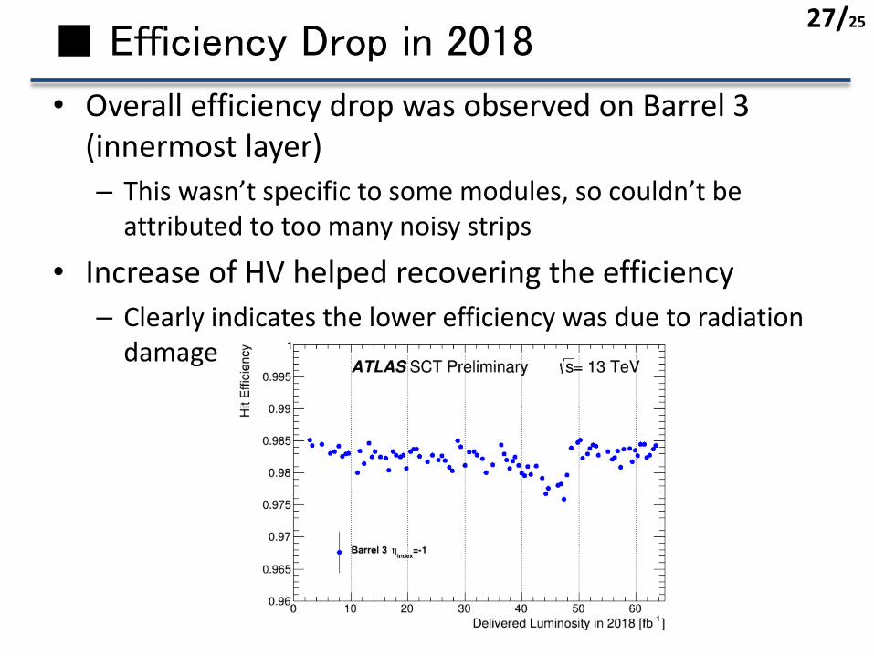
■ Efficiency Drop in 2018
• Overall efficiency drop was observed on Barrel 3 (innermost layer)
– This wasn’t specific to some modules, so couldn’t be attributed to too many noisy strips
• Increase of HV helped recovering the efficiency
– Clearly indicates the lower efficiency was due to radiation damage
27/25

■ Global reconfiguration
• Introduction of GR was effective to reduce the number of problematic chips– This is important not only in terms of data quality (efficiency etc.), but
also of DAQ; too many noisy chips may interrupt DAQ due to too high data transmission rate
w/o GR
w/ GR
28/25

■ Type-inversion and “knee”
• After type-inversion, the depletion zone grows from the back electrode– Depletion zone doesn’t contact with strips before full depletion
→ This may be a cause of “two-step” structure of noise (or capacitance)
• The knee was reported by RD48 project in 1999
* Exact mechanism of “knee” is still under investigation
p+ strip
n+ electrode
n- bulk
p- bulk
typeinv.
Depletion zoneROSE Collab. CERN/LHCC 2000-009
29/25
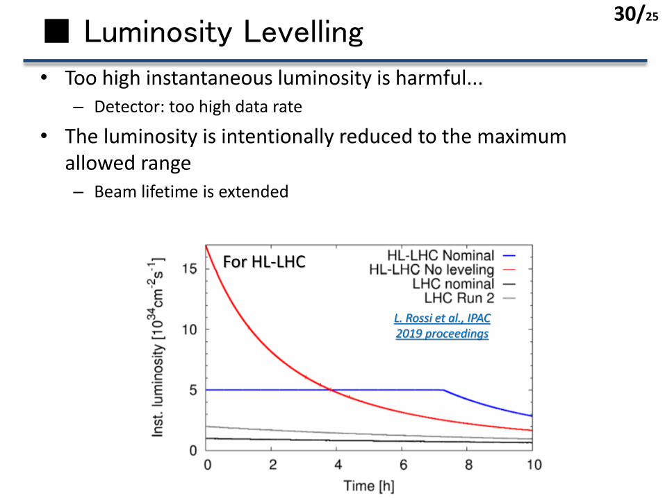
■ Luminosity Levelling
• Too high instantaneous luminosity is harmful...– Detector: too high data rate
• The luminosity is intentionally reduced to the maximum allowed range– Beam lifetime is extended
For HL-LHC
L. Rossi et al., IPAC 2019 proceedings
30/25
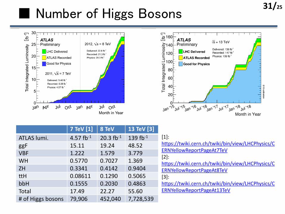
■ Number of Higgs Bosons
7 TeV [1] 8 TeV 13 TeV [3]
ATLAS lumi. 4.57 fb-1 20.3 fb-1 139 fb-1
ggF 15.11 19.24 48.52VBF 1.222 1.579 3.779WH 0.5770 0.7027 1.369ZH 0.3341 0.4142 0.9404ttH 0.08611 0.1290 0.5065bbH 0.1555 0.2030 0.4863Total 17.49 22.27 55.60# of Higgs bosons 79,906 452,040 7,728,539
[1]: https://twiki.cern.ch/twiki/bin/view/LHCPhysics/CERNYellowReportPageAt7TeV [2]: https://twiki.cern.ch/twiki/bin/view/LHCPhysics/CERNYellowReportPageAt8TeV[3]: https://twiki.cern.ch/twiki/bin/view/LHCPhysics/CERNYellowReportPageAt13TeV
31/25
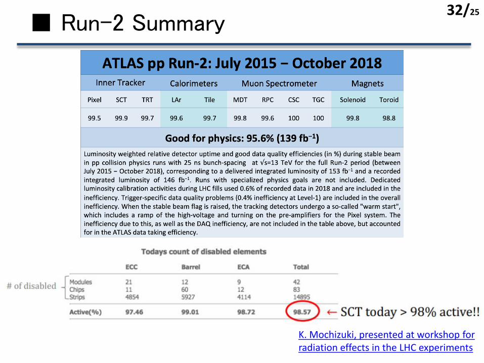
■ Run-2 Summary
K. Mochizuki, presented at workshop for radiation effects in the LHC experiments
32/25
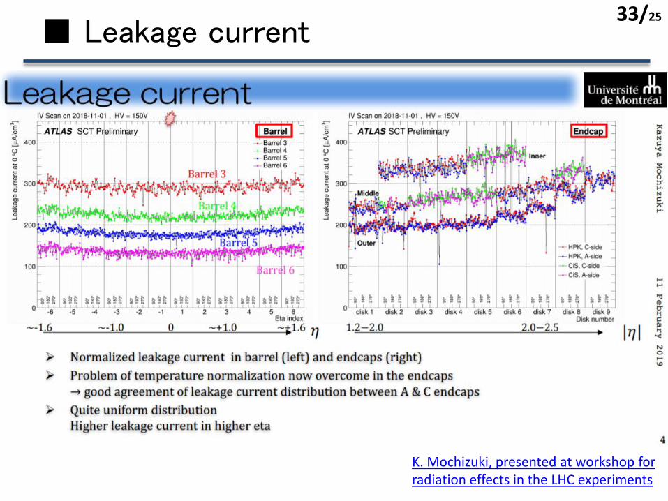
■ Leakage current
K. Mochizuki, presented at workshop for radiation effects in the LHC experiments
33/25
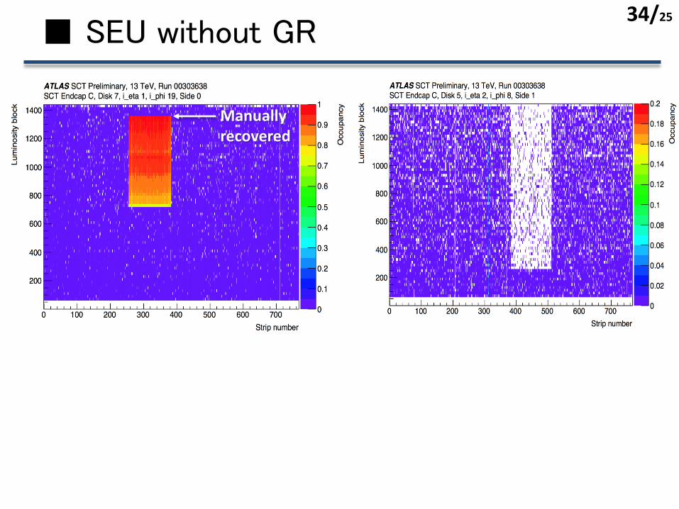
■ SEU without GR
Manually recovered
34/25
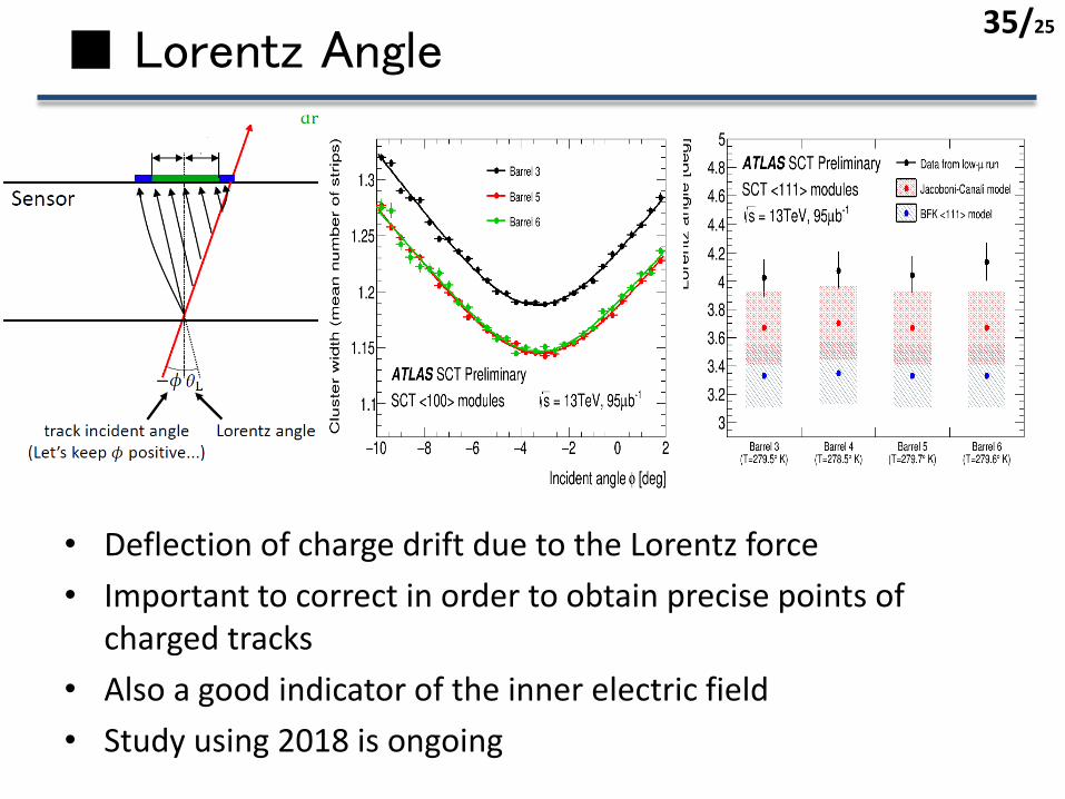
■ Lorentz Angle
• Deflection of charge drift due to the Lorentz force
• Important to correct in order to obtain precise points of charged tracks
• Also a good indicator of the inner electric field
• Study using 2018 is ongoing
35/25