Performance analysis of IPv4 / IPv6 protocols over the...
81
Performance analysis of IPv4 / IPv6 protocols over the third generation mobile network DANIEL ABAD CAMARERO Master’s Degree Project Stockholm, Sweden XR-EE-LCN 2014:004
Transcript of Performance analysis of IPv4 / IPv6 protocols over the...

Performance analysis ofIPv4 / IPv6 protocols over the
third generation mobile network
DANIEL ABAD CAMARERO
Master’s Degree ProjectStockholm, Sweden
XR-EE-LCN 2014:004


KTH Royal Institute of Technology School of Electrical Engineering (EE) Laboratory for Communication Networks
Performance analysis of IPv4 / IPv6 protocols
over the third generation mobile network.
Daniel Abad Camarero
Examiner and academic advisor: Viktoria Fodor
August, 2014
Stockholm, Sweden


“Success is stumbling from failure to failure
with no loss of enthusiasm.”
-Winston Churchill-


1
Abstract
Currently, the IPv4 protocol is heavily used by institutions, companies and
individuals, but every day there is a higher number of devices connected to the
network such as home appliances, mobile phones or tablets. Each machine or device
needs to have its own IP address to communicate with other machines connected to
Internet. This implies the need for multiple IP addresses for a single user and the
current protocol begins to show some deficiencies due to IPv4 address space
exhaustion.
Therefore, for several years experts have been working on an IP protocol
update: the IPv6 128-bit version can address up to about 340 quadrillion system
devices concurrently. With IPv6, today, every person on the planet could have millions
of devices simultaneously connected to the Internet.
The choice of the IP protocol version affects the performance of the UMTS
mobile network since the experts are still optimizing the network architecture and the
devices to support the IPv6 protocol. The aim of the project is to measure how the IPv6
protocol performs compared to the previous IPv4 protocol. It is expected that the IPv6
protocol generates a smaller amount of signalling and less time is required to fully load
a web page. We have analysed some KPIs (IP data, signalling, web load time and
battery) in lab environment using smartphones, to observe the behaviour of both, the
network and the device.
The main conclusion of the thesis is that IPv6 really behaves as expected and
generates savings in signalling, although the IP data generated is larger due to the size
of the headers. However, there is still much work as only the most important
webpages and the applications with a high level of market penetration operate well
over the IPv6 protocol.
Keywords:
UMTS, signalling, network protocols, IPv4, IPv6, performance, analysis, IP data, radio
access network, core network, comparison.

2

3
Acknowledgments
I would like to thank to all those who have made this work possible. First of all, I
want to extend my sincere thanks and appreciation to my family for their
unconditional belief. Their continued help and support, even in the distance, have
helped me to reveal all the capacities that I had and to be myself.
I would also like name to the teachers and researchers who have contributed to
my education and express my gratitude to all people involved in this Master Thesis,
namely:
To my supervisor and examiner Viktoria for her help during the preparation of
the project, her guidelines during the master thesis work and for the thesis
review.
To Esther, Ignacio, Santiago, Sandra, Servio and Fernando for their extensive
feedback and guidance throughout the entire thesis.
To all other people who have worked with me in Madrid for their concerns,
advices and the amount of knowledge which they have taught me.
Finally my thanks go to my friends and colleagues in Madrid, Stockholm and
around the world, both at university and home, for the funny and relaxed moments.
These seven years could never have been completed without them.

4

5
Table of Contents
Abstract _____________________________________________________________ 1
Acknowledgments _____________________________________________________ 3
Table of Contents ______________________________________________________ 5
List of figures _________________________________________________________ 7
List of tables __________________________________________________________ 9
List of acronyms ______________________________________________________ 11
Introduction _________________________________________________________ 13
1.1 Overview _____________________________________________________________ 13
1.2 Motivation and goals ____________________________________________________ 14
1.3 Structure of the Thesis __________________________________________________ 15
1.4 Related work __________________________________________________________ 16
Background _________________________________________________________ 19
2.1 The mobile communication system ________________________________________ 19
2.1.1 The third generation mobile network ____________________________________________ 19
2.1.2 UMTS Architecture __________________________________________________________ 20
The Mobile Station (Device) ______________________________________________________ 20
The radio access network (RAN) ___________________________________________________ 21
The core network (CN) ___________________________________________________________ 21
2.2 The signalling protocols __________________________________________________ 22
2.3 The TCP/IP protocol stack ________________________________________________ 24
2.3.1 The network layer protocols ___________________________________________________ 25
IPv4 Protocol __________________________________________________________________ 25
IPv6 Protocol __________________________________________________________________ 28
IPv6 compared to IPv4 ___________________________________________________________ 30
2.3.2 The transport layer protocols __________________________________________________ 31
2.3.3 The application layer protocols _________________________________________________ 33
2.4 UMTS performance on the internet network _________________________________ 33
2.4.1 Protocol operation in UMTS architecture _________________________________________ 34
IP tunnelling call setup ___________________________________________________________ 34
TCP/IP stack operation ___________________________________________________________ 36
6
2.4.2 Web optimization for IP protocol in UMTS ________________________________________ 37
Testbed implementation _______________________________________________ 39
3.1 Testbed environment ___________________________________________________ 39
3.1.1 Steps of the testbed deployment _______________________________________________ 41
3.1.2 Problems and Issues solved ____________________________________________________ 41
3.2 Scenario 1: Web Browsing ________________________________________________ 45
3.3 Scenario 2: Apps _______________________________________________________ 45
3.4 KPIs measured _________________________________________________________ 46
3.4.1 KPIS for browsers and apps ____________________________________________________ 47
IP data and number of IP packets __________________________________________________ 47
RNC signalling __________________________________________________________________ 48
3.4.2 Browser KPIs _______________________________________________________________ 49
Web Load time _________________________________________________________________ 49
3.4.3 Applications KPIs ____________________________________________________________ 49
Battery power__________________________________________________________________ 49
3.5 Expected results ________________________________________________________ 50
Performance Evaluation _______________________________________________ 53
4.1 Browser Results ________________________________________________________ 53
4.1.1 Data Volume _______________________________________________________________ 53
4.1.2 RNC Signalling ______________________________________________________________ 55
4.1.3 Web load time ______________________________________________________________ 56
4.2 Apps Results ___________________________________________________________ 58
4.2.1 Data Volume _______________________________________________________________ 58
4.2.2 RNC Signalling ______________________________________________________________ 59
4.2.3 Battery consumption _________________________________________________________ 62
4.3 Analysis of the results ___________________________________________________ 64
Conclusions and future work ____________________________________________ 67
5.1 Conclusions ___________________________________________________________ 67
5.2 Future work ___________________________________________________________ 68
References __________________________________________________________ 71

7
List of figures
Figure 1-1: IPv4 / IPv6 Packet Loss Rate ........................................ 16
Figure 2-1: UMTS architecture model ......................................... 20
Figure 2-2: PDP Creation over RANAP protocol .............................. 23
Figure 2-3: PDP Creation over GTP protocol ............................... 23
Figure 2-4: Signalling protocols scheme ......................................... 24
Figure 2-5: IPv4 Address Structure ..................................... 26
Figure 2-6: IP address settings for the five IP address classes ..... 26
Figure 2-7: IPv4 header ......................................... 27
Figure 2-8: IPv6 Address Structure ..................................... 28
Figure 2-9: IPv6 header ..................................... 29
Figure 2-10: Comparative between IPv4 andIPv6 headers ........... 30
Figure 2-11: The transport level protocols .................................... 32
Figure 2-12: HTTP and DNS protocols in Whireshark ................... 33
Figure 2-13: Attach on the network ..................................... 34
Figure 2-14: PDP Context Activation ..................................... 34
Figure 2-15: DNS query and response ..................................... 35
Figure 2-16: Detach request ..................................... 35
Figure 2-17: PDP context activation ..................................... 35
Figure 3-1: Laboratory layout ......................................... 39
Figure 3-2: Context PDP Reject (Insufficient resources) ............... 42
Figure 3-3: No response from DNS ..................................... 42
Figure 3-4: Standard query response from DNS .......................... 43

8
Figure 3-5: Service no subscribed ...................................... 43
Figure 3-6: IP Address assignation ...................................... 44
Figure 3-7: Delete PDP context and new activation ...................... 44
Figure 3-8: Whireshark Interface for End-Points .......................... 47
Figure 3-9: IP data measurement ...................................... 47
Figure 3-10: RNC signalling measurement ...................................... 48
Figure 4-1: IP Data Volume for Google ....................................... 54
Figure 4-2: IP Data Volume for Kame ....................................... 54
Figure 4-3: RNC signalling for Google ....................................... 55
Figure 4-4: RNC signalling for Kame ....................................... 56
Figure 4-5: Load time for Google ....................................... 57
Figure 4-6: Load time for Kame ....................................... 57
Figure 4-7: IP data for Facebook Messenger ................................ 58
Figure 4-8: IP data for Facebook ....................................... 58
Figure 4-9: IP data for Google Maps ....................................... 59
Figure 4-10: IP data for Youtube ....................................... 59
Figure 4-11: RNC Signalling for Facebook Messenger ................... 60
Figure 4-12: RNC Signalling for Facebook ....................................... 60
Figure 4-13: RNC Signalling for Google Maps ............................... 61
Figure 4-14: RNC Signalling for Youtube ...................................... 61
Figure 4-15: Battery consumed by Facebook Messenger ............... 62
Figure 4-16: Battery consumed by Facebook ................................ 62
Figure 4-17: Battery consumed by Google Maps ........................... 63
Figure 4-18: Battery consumed by Youtube .................................. 63

9
List of tables
Table 3-1: App testing ................................................ 46
Table 4-1: IP packets for browsing (number of fragments) .............. 54
Table 4-2: IP data for browsing (kilobytes) ...................................... 54
Table 4-3: RNC Signalling for browsing (number of messages) ....... 55
Table 4-4: Load time (seconds) ........................................................ 56
Table 4-5: IP Data for apps (Kilobytes) ............................................ 58
Table 4-6: RNC Signalling for apps (number of messages) ............... 60
Table 4-7: Battery for apps (percentage consumption) ...................... 62
Table 4-8: Applications operation over IP ......................................... 64

10

11
List of acronyms
2G Second Generation
3G Third Generation
4G Fourth Generation
3GPP 3rd Generation Partnership Project
APN Access Point Network
CDMA Code Division Multiple Access
Cell_DCH Cell Dedicated Channel
Cell_FACH Cell Forward Access channel
Cell_PCH Cell Paging Channel
CN Core Network
DHCP Dynamic Host Configuration Protocol
DNS Domain Name System
EDGE Enhanced Data Rates for GSM Evolution
EGP Exterior Gateway Protocol
ESP Encapsulating Security Payload
GGSN Gateway GPRS support node
GPRS General Packet Radio Service
GSM Global System for Mobile communications
GTP GPRS Tunnelling Protocol
HSPA High-Speed Packet Access
HSDPA High-Speed Downlink Packet Access
HSUPA High-Speed Uplink Packet Access
HTTP HyperText Transfer Protocol
IETF Internet Engineering Task Force
ICMP Internet Control Message Protocol
IP Internet Protocol
IPIP IP-within-IP Encapsulation Protocol
IPSec Internet Protocol Security
IPv4 Internet Protocol version 4
IPv6 Internet Protocol version 6
ITU International Telecommunication Union
KPI Key Performance Indicator

12
LTE Long Term Evolution (4G)
ME Mobile Equipment
MPLS-in-IP Multiprotocol Label Switching in IP
MS Mobil Station
NAS Non-access stratum
NBAP NodeB Application Part
OSPF Open Shortest Path First
PDP Packet Data Protocol
PSTN Public Switched Telephone Network
RAB Radio Access Bearer
RAN Radio Access Network
RANAP Radio Access Network Application Part
RFC Request for comments
RLC Radio Link Control
RNC Radio Network Controller
RRC Radio Resource Control
SGSN Serving GPRS Support Node
SIM Subscriber Identity Module
SMTP Stream Control Transmission Protocol
STCP Stream Control Transmission Protocol
TCP Transmission Control Protocol
UDP User Datagram Protocol
UE User Equipment
UMTS Universal Mobile Telecommunication System
URA UTRAN Routing Area
URA_PCH URA Paging channel
USIM UMTS Subscriber Identity Module
UTRAN UMTS Radio Access Network
W-CDMA Wideband Code Division Multiple Access

13
Chapter 1
Introduction
This chapter provides an introduction to the subject of this master’s thesis
project in order to help readers understand the scope of this project. Next, the
problems addressed in this thesis project are described, followed by a statement of the
project’s aim and goals. The chapter concludes with an overview of the related work
on this topic.
1.1 Overview
Due to the convergence of the mobile networks, which means the capacity of
providing voice services through the packet switched domain, the number of users
who demand a fast and reliable data connection is rapidly growing. It is quite
important for phone companies to provide proper network architecture capable of
deliver the multimedia information.
Besides, the number of active mobile subscriptions has increased from 268
million of mobile subscriptions in 2007 to 2315 million in 2014, according to the
International Telecommunication Union (ITU) statistics [1], thus the current network
definition must support all these subscribers.
The mobile communication networks have been adapted, from its inception to
the present, gradually to match all the needs that have been brought. From the mobile
communication network of first generation to current networks which are composed
by a mixture of elements of 2G, 3G and 4G technologies [2].
Network protocols such as IP, TCP or HTTP have evolved in parallel to the
evolution of the networks. In recent years, the more common is the IPv4 protocol [3].
But in the early 1990s, with the increasing number of IP addresses being requested, it
was clear that they would eventually run out. In fact, during 1993, experts realized that
the address space would not be enough as is described in RFC1519: “At this rate of
growth, all class B's will be exhausted” [4]. As of 31 January 2011, the pool of
unallocated IPv4 addresses officially ran out [5].

14
That is when the new addressing system begins to be defined, it is known as
IPv6. The aim is to replace the old version of IP protocol with this new one, improving
most of the technical aspects of the fourth version. All changes are explained in
Chapter 2 of this report.
1.2 Motivation and goals
We have been hearing a lot about IPv6 implementation and the diversity it can
bring to our lives. It has a very large address space which has been designed by
keeping in mind the future needs.
The IPv6 technology was designed to allow a bigger number of addresses;
improving the service quality and reducing the processing time on the routers (IPv6
does not fragment datagrams and neither check the integrity of the header -this
happens at TCP level-).
Due to these specifications and as explained in chapter two, the headers of
both protocols are different, both in size and in terms of field’s definition. The
addressing of all elements involved in the communication is made through the IP
network protocol so the datagrams which are sending to the Internet are different
depending on the IP version used. The IPv6 datagrams are larger (since the header is
bigger and there is not intermediate fragmentation) and are processed faster, so the
performance of the network is different.
In recent years, large companies have not only to ensure that both, the
network and the devices support IPv6 technology, but using this protocol does not
consume a lot of resources. The operators have to know whether the protocol is
operating correctly or not. For this purpose, an analysis should be made about the IPv6
protocol improvements on the functionalities borrowed from IPv4. Large telecom
companies are asking the manufacturers to support Dual Stack functionality, which will
allow made the network connection through IPv4 or IPv6. The aim of this master thesis
project is to see how the most common and popular webpages and applications
available on the market work through the mobile device. Thus, we will make several
tests in order to compare the performance using different protocol versions.
Undoubtedly, the main service which we are going to test is if the webpages
supports IPv6. This is quite interesting because most people use the device and data
connection to access to the Internet cloud. Furthermore, it is also interesting to know
if the most famous applications perform well over the IPv6 protocol.

15
1.3 Structure of the Thesis
To carry out and accomplish the objectives of this project, qualitative and
quantitative methods have been used. The first parts of this master thesis project are
based on a qualitative research methodology and then, with the information collected
from the test on the laboratory, initiate a quantitative study.
The master thesis begins with a theoretical background study. This part
includes the third mobile network (UMTS) architecture and the elements involved on
the communication, especially within radio and core parts. We have mainly focused on
the signalling and network protocols that we expect to use, including a deep analysis
about internet protocol (IP). This section also includes a description of the UMTS
network operation, linking the network elements explained on the architecture
definition with the protocols responsible for each one of the operations.
Then, we discuss the laboratory configuration phase in order to evaluate the
proposed performance parameters for both, webpages and apps. From the three
options available to perform the testing (mathematical simulation, testbed or test over
real network), we have discarded the mathematical simulation from the very
beginning because it does not provide real information and the results are theoretical.
Of the two remaining options, we have chosen the option of testbed which consists of
a real network, but with controlled access to prevent interferences from other
equipment that may appear in the real network. We also discuss what performance
indicators the project will look at, why they are important, what kind of interactions or
effects of input parameters we expect and how they are going to be evaluated.
The report continues with the evaluation methodology of the thesis based on
several measurements taken on the laboratory to ensure the feasibility of the results,
thus each test is going to be repeated many times. The results of the measured KPIs
are presented as well as the explanation of the results. To end this chapter, we make a
comparison between the expected results (before carry out the tests) with the real
results obtained in the laboratory.
The final part of the project analyses the results collected on the laboratory,
obtaining conclusions about the behaviour of the network, the devices, the operating
systems, the webpages and the applications tested.
To finish the master thesis, the report raises possible lines of research in the
future, which would serve as support for master thesis or PhD students who are
planning to work on the UMTS performance over the internet protocol.
16
1.4 Related work
In this section, several previous studies conducted in areas relevant to this
master’s thesis are summarized, mainly related to the performance of the TCP/IP stack
over mobile networks.
The most of the previous work which have been carried out is related to the
optimization of the TCP transport protocol to improve the throughput (amount of
information flowing through a network according to the time). Mun Choon Chan and
Ramachandran Ramjee [6] proposed and evaluated a mechanism called Window
Regulator to improve the performance of TCP. They also demonstrated the efficiency
of an algorithm for sharing the transmission and reception buffer improving the
latency.
There are also too many studies about the TCP performance according to the
congestion method used. Luca De Cicco and Saverio Mascolo checked [7] that TCP
behaves similarly regardless of the congestion mechanism used.
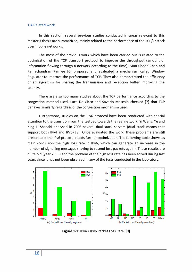
Furthermore, studies on the IPv6 protocol have been conducted with special
attention to the transition from the testbed towards the real network. Yi Wang, Ye and
Xing Li Shaozhi analysed in 2005 several dual stack servers (dual stack means that
support both IPv4 and IPv6) [8]. Once evaluated the work, these problems are still
present and the IPv6 protocol needs further optimization. The following table shows as
main conclusion the high loss rate in IPv6, which can generate an increase in the
number of signalling messages (having to resend lost packets again). These results are
quite old (year 2005) and the problem of the high loss rate has been solved during last
years since it has not been observed in any of the tests conducted in the laboratory.
Figure 1-1: IPv4 / IPv6 Packet Loss Rate. [9]

17
Researchers from the University of Delft have also carried out a comparative
analysis among protocols IPv4 - IPv6 at [9] from which can be concluded that the
loading time and the delay is less in native IPv4 tunnels than in IPv6 tunnels, because
the version 6 of the protocol is less optimized than the version 4 and therefore there is
less number of optimal paths (see information about the IP tunnelling on the chapter
two). In addition, researchers from the University of Budapest [10] have studied the
methods of transition from IPv4 to IPv6 in the UMTS networks, discovering some
limitations on non-native IPv6 tunnels. The main conclusion of these investigations is
that we must stress the need for further studies aiming to help and urge the process
towards the global native IPv6 coverage.
A previous study about the browsing optimization has been conducted as well
by Binoy Chemmagate in Nokia networks [11]. This research has analysed some HTTP
and TCP issues on web browsing, testing alternative protocols as SPDY (that is
a trademark of Google and is not an acronym) which provides header compression and
multiplexing techniques. Using SPDY protocol we reduce the Page Load Time of a
website, thus is highly recommended.
Another important published paper is about the performance improvement in
the application and session layers [12]. In general, we can observe that application and
session layer techniques have a dominating effect in improving the web performance
and commercial web servers and browsers should implement the HTTP-pipelining
scheme, which provides noticeable benefits end-to-end user performance (in spite of
the deployment of these services can be expensive).

18

19
Chapter 2
Background
The aim of this chapter is provide all the technical background to the reader in
order to make easier the understanding of the project’s context. This chapter begins by
introducing the third generation mobile networks (3G) and the signalling protocols
involved on the communication.
To complete the theoretical framework, a general overview about the network
protocols is presented. The IP protocol is defined, which is the most important in the
research since the purpose of the master thesis is to evaluate it, as well as the
evolution from IPv4 (used up to now) to IPv6. A brief introduction is also presented
related the transport protocols and the application part.
2.1 The mobile communication system
The remarkable success of mobile communications systems of second
generation (2G) defined on [13] [14] and the needed to develop faster and more
secure telecommunications services are the beginning of 3G.
To satisfy these demands, getting a similar quality than services offered by fixed
networks and with a global perspective, emerges the mobile communication systems
called third generation (3G).
2.1.1 The third generation mobile network
The 3G technology emerges to match the demanding needs of the users. Such
technology is specified in the IMT-200 standardization defined by the ITU [15] and
includes plenty of standards.
In Europe and Japan is standardized the UMTS system, which is based on the
W-CDMA technology managed by the 3GPP [16] organization. The other mobile
communications system which is regulated by the IMT-2000 specification is known
with the name of CMDA2000. However, this technology will not be covered in this
report since the whole Europe uses the UMTS standard.

20
The main novelty of this technology, compared to earlier mobile networks, is
that network architecture is divided into two domains, the UTRAN access part and the
core network which is responsible for the interconnection to Internet or the public
switched telephone network (PSTN).
2.1.2 UMTS Architecture
The definition of the architecture is quite simple and intuitive, there are three
distinct structures: the mobile station (MS), the radio network (UTRAN) and the core
network (CN). Theoretical framework is widely explained in [17] [19] using the
specifications defined by 3GPP organism [18].
Importantly, this project only covers the study and analysis of the UMTS
technology. Real networks, as seen from the operator's side, are the result of a set of
technologies such as GSM (2G), UMTS (3G) and LTE (4G) in order to satisfy all users.
Therefore, the reader must keep in mind that the scheme depicted corresponds to a
purely UMTS network and not to a current and real network operator one.
Figure 2-1: UMTS architecture model.
The Mobile Station (Device)
The outer part of the network located on the side of the user and called the
device later on in this report. The device is divided into two parts, the mobile
equipment (ME) which is the physical device (it can be a smartphone, a cell phone or a
tablet), and the USIM card. The USIM card is responsible for storing information about
the user ID and the state of the network connection, including authentication
algorithms as well.

21
The device is quite stable within the network since we are working with
commercial devices ready to run on the real network (configured with well-tested
operating systems), thus it is not necessary more detail to further understand the
context of the project. The reader can get more details about the user part in the
specification in [21].
The radio access network (RAN)
The UMTS Radio Access Network (UTRAN) technology is specified in
the 3GPP TS 25.-series specifications [16] and more specifically in the standard TS
25.401 [22].
This part covers the structure between the device and the core network. The
fundamental mission of the RAN is to provide the means of transmission for the
control plane (signalling) and the user data.
The RAN is formed by the Node-B and the RNC. The Node-B communicates
directly with the user device and provides radio frequency coverage to perform the
communication. It is a transparent antenna, which means it does not generate any
management issue in the data fragments, but the information is transmitted as it has
been received. The RNC is the control unit which interconnects several Nodes-Bs
managing the radio transceivers in the Node B equipment and selecting the signals
received from the device, as well as management tasks like soft handoff or common
and dedicated channels.
Transmission services offered by the access network to carry the information of
the device (both signalling and data) to / from the core network are bearer services
whose aim is the provision of a certain transmission capacity. The access network is
responsible for managing the use of the radio resources available for the provision of
carrier services efficiently.
The core network (CN)
The core network comprises the switching and routing equipments in charge of
forwarding the information to other networks (i.e. IP Internet). This part of the
network is divided into two domains, the packet (for data connections) and the circuit
domain (for voice connections and calls). Since all actions and tests required to match
the needs of this project are directly involved with the data part, this report will focus
only on the packet domain. For more information about circuit domain, consult the
specification [23] or the book [24].
The data core network consists of two essential components, the SGSN and the
GGSN. The SGSN is a service node responsible for providing and ensuring access to the
devices connected to the network and is also responsible for the authentication and
assignation of the quality service to each participant in the communication. It is in

22
charge of managing the devices mobility, tracking the location of these phones, as well
as the routing and transferring of data packets.
The GGSN is the gateway or access point to other networks and, in some cases,
is the Access Point Network (APN). This equipment assigns the IP address to the device
(through the PDP context activation), establishing and implementing the rules of
navigation and the billing feature.
The HLR equipment is responsible for the user authentication and is also shared
between CS and PS domains [25]. It is one of the most important parts of the mobile
service provider containing all subscribers which are able to access to the service.
The core network performs traffic and signalling transport as well as
intelligence functions. The routing is done through intelligence functions which
comprise logic and control of certain services offered. The core domain is also in
charge of the mobility management.
This part of the network acts also as gateway and connects the architecture
with other communication networks, so that communication is possible not only
between UMTS mobile users, but also with those which are connected to other
networks (as for example the PSTN).
2.2 The signalling protocols
The signalling protocols are used to check if the phone is properly attached to
the network or if there are some issues. All protocols are specified in the book [26].
The most important are the RRC (Radio Resource Control), NBAP (Node B
Application Part), RANAP (Radio Access Network Application Part) and GTP (GPRS
Tunnelling Protocol) and the basic description of each one is as follows:
RRC: It is the protocol that defines the control mode of connection of the
device in the network, thus it manages the flow of signalling between the user device
and the Node B. There are four possible modes of connection such as Cell_DCH,
Cell_FACH, Cell_PCH and URA_PCH. These statements represent the degree of
connection of the device to the network and depend on the configuration of the
inactivity timer. If the phone is in a full connection state (Cell_DCH), the network
requires many more resources than if the device is on Cell_FACH state (similarly to idle
mode and using keep-alives in order to keep the device connected to the network).
Switching from the Cell_DCH state to Cell_FACH saves approximately 80% battery and
power consumption form the network side.

23
NBAP: This protocol is also responsible for the control and signalling part,
managing the Node B by the RNC.
RANAP: As the previous protocols, the RANAP is also responsible for the
signalling. In this case it handles the control in the routing between radio and core
part. For our particular network, it handles the control plane between the RNC and the
SGSN, using the RANAP protocol carried on SCTP (defined below).
Figure 2-2: PDP Creation over RANAP protocol.
GTP: The GTP protocol is a group of network based protocols that are used to
carry the GPRS service in UMTS networks. This protocol provides confirmation that the
PDP context has been successfully created by the SGSN (figure 2-3). Therefore the
sender has been identified with a unique IP address in order to be able to carry out the
transmission of the desired datagrams. The tunnel which is created during the PDP
context remains open throughout the connection and is used to send data (see more
information about IP tunnelling call setup in the section 2.4.1).
Figure 2-3: PDP Creation over GTP protocol.

24
GTP
These protocols are needed to understand the topology of the lab layout and to
interpret how the network elements are interconnected on the radio and core
interfaces. The signalling process on the UMTS network is described in detail on the
coming protocol operation section.
Figure 2-4: Signalling protocols scheme.
The signalling protocols are very useful to check whether the device is properly
attached to the network, but do not provide too much information in terms of data
exchanged with Internet cloud. The information directed to the internet cloud travels
encapsulated over the network layer protocols (i.e. IP, TCP, or HTTP).
2.3 The TCP/IP protocol stack
A network protocol is a set of rules that specify the data exchange policy and
the orders for communication between network equipments. To classify them there
are two models, the OSI and the TCP/IP. The OSI model was proposed by the ISO in the
1980s comprising seven layers and each protocol corresponds to one of them: physical
layer, data link layer, network level (IP, etc.), transport layer (TCP, UDP, STCP, etc.),
session layer, presentation layer and application layer (DNS, HTTP, etc.). The evolution
of the OSI model is the TCP/IP stack classification which split the protocols in four
layers and is used currently for internet connections.
RRC NBAP RANAP

25
The transport layer protocols are responsible for deciding how the information
has to be encapsulated and transmitted dividing all information into packets. These
protocols are also in charge of the end to end control of the transmission.
2.3.1 The network layer protocols
The network layer protocols are rules that define how communication between
different computers or devices has to be established. The most common network layer
protocol is the IP (the datagram can be sent between two devices without prior
agreement) which specifies the technical format of packets and the addressing scheme
for devices to communicate over the network.
With the growth of the Internet it is expected that the number of unused IPv4
addresses will eventually run out because every device – including computers,
smartphones and game consoles- that connects to the Internet requires an IP address.
IPv6 is an evolutionary upgrade to the IPv4, which will coexist with the older one for
some time. With the objective of comparing IPv4 and IPv6 web browsing and
smarphone’s applications perform over current mobile networks, this section presents
a brief introduction of Internet Protocol in its two standard versions: IPv4 and IPv6.
IPv4 Protocol
The IPv4 protocol was defined in 1981 by the IETF (Internet Engineering Task
Force) which is the organization responsible for defining the standards for Internet
protocols. This protocol was defined in [3] and was the first Internet protocol
implemented on a large scale. The initial specification of the protocol was used to
connect a small group of organizations. When this protocol was defined, the number
of machines connected to the Internet was much lower than at present. So some
features (listed below) have been somewhat obsolete and experts have realized some
deficiencies.
However, IPv4 is the most widely deployed Internet Protocol used to connect
devices to the Internet. Today it is still used for most of the many connections that are
carried out through the Internet.
IPv4 uses a 32-bit address scheme allowing a total of 232 addresses (over 4
billion addresses). The 32 bits are separated into four groups of bits which are called
octets, see figure 2-5 from [27] below. Depending of the format used for IP, there are
bits represented as decimal numbers separated by dots in decimal-dot system.
Generally, the first 16 bits are used to represent the network mask or subnet and the
rest of them for indicate the host. Thus, two IP addresses with the same first part and
different last bits correspond to a different host in the same subnet.

26
Figure2-5: IPv4 Address Structure.
As is described in [3] and [28], there are different types of addressing,
according to the number of bits used to define the mask network or host (see figure
2-6 from [28] below):
Figure 2-6: IP address settings for the five IP address classes.
Addressing type A allows a smaller number of networks (126 considering all
available space for network type A), but a larger number of hosts on each subnet. If
another routing division is selected, the number of networks increase but the number
of hosts stored is reduced considerably. The broadcast addresses are used to send
traffic to all nodes on a subnet.
An IPv4 packet consists of a header section and a data section. Packet size is 20
bytes of header and a maximum of 65.535 bytes of data. An example of IPv4 header is
shown in figure 2-7, the graphic has been extracted from [29] based on the
specifications defined in [3].

27
Figure 2-7: IPv4 header.
According to [3], the description of the IPv4 protocol header functionalities is
explained below:
Version: Describes the version of the protocol, in this case the RFC791 [3]
describes the version 4. This field occupies a length of 4 bits.
IHL: Describes the total length of the IP header, i.e. excluding the size of the
data being transmitted. This length is represented in 32-bit words. The length
necessary to store this field is 4 bits and the default size (unless otherwise will be
noted) is 0101 (5x32bits = 20bytes).
Type of service: Indicates the quality of service requested by the IP datagram
providing an indication of the abstract parameters of the quality of service desired.
These parameters are used to guide the selection of the actual service parameters
when transmitting a datagram through a particular network. It consists of network
priority and 8 bits are needed to store this field.
Total length: Contains the number of bits composing the total datagram header
and the number of data. It occupies 16 bits.
Identification: It is a unique value assigned to the fragment being transmitted
by the sender of the datagram which allows to the receiver the identification of the
received datagram fragment. 16 bits are required to store this field.
Flags: Contains the values O (reserved), DF (indicating whether fragmentation is
allowed or not) and MF (if there are more fragments on transmission or it is the last
one). Each value occupies 1 bit, so that a total length of 3 bits are necessary.
Fragment Offset: Indicates the displacement of the fragment as part of the
complete datagram in units of 8 bytes. It is required to reassemble the datagram on
the receiver side. Contains a value from 0 (if there is just one fragment) to 65536 and
the field length is 13 bits.
Time to live (TTL): Sets the lifetime (in seconds) which the datagram or the
fragment may remain in the network without being dropped. The aim is to prevent a
datagram for travelling all the time without being intercepted by any end user. The
length of this field is 8 bits.
Protocol: Describes the high-level protocol to which IP should deliver the
datagram (see next sections about transport and application protocols). This field
occupies a length of 8 bits.
28
Checksum: This field is used to verify and check the information contained in
the header. The total length is 16 bits.
Source IP Address: Source address (host sender) represented with 32 bits.
Destination IP Address: Destination address (host receiver) represented with 32
bits.
Options: Field with a maximum length of 40 additional bytes (10x32 bits) to
introduce additional actions, if necessary.
Padding: Padding field. Complete with 0s until the next group of 32 bits begins.
Related the packet fragmentation in the routers, both transmission and
reception routers support it and the default packet size is 576 bytes.
The IPv4 protocol uses some specific protocols, the ARP (Address Resolution
Protocol) to resolve an IP address to a link-layer address, and the ICMP Router
Discovery is optional to determinate the IPv4 address of the best default gateway.
IPv6 Protocol
As already explained in the first chapter of this report, when the IPv4 protocol
was defined, nobody realized about of the high expansion of Internet usage that may
take place in the future. The version 4 of the protocol was designed to address 32 bits,
but in the future could be not enough since there are plenty of devices that make use
of Internet.
Furthermore of the address space problem, other features have been
considered to improve, such as safety issues in IPv4, traffic prioritization, mobility
within nodes, etc. Besides, in IPv6 there is a flow label field which allows using
communication flows and quality of service.
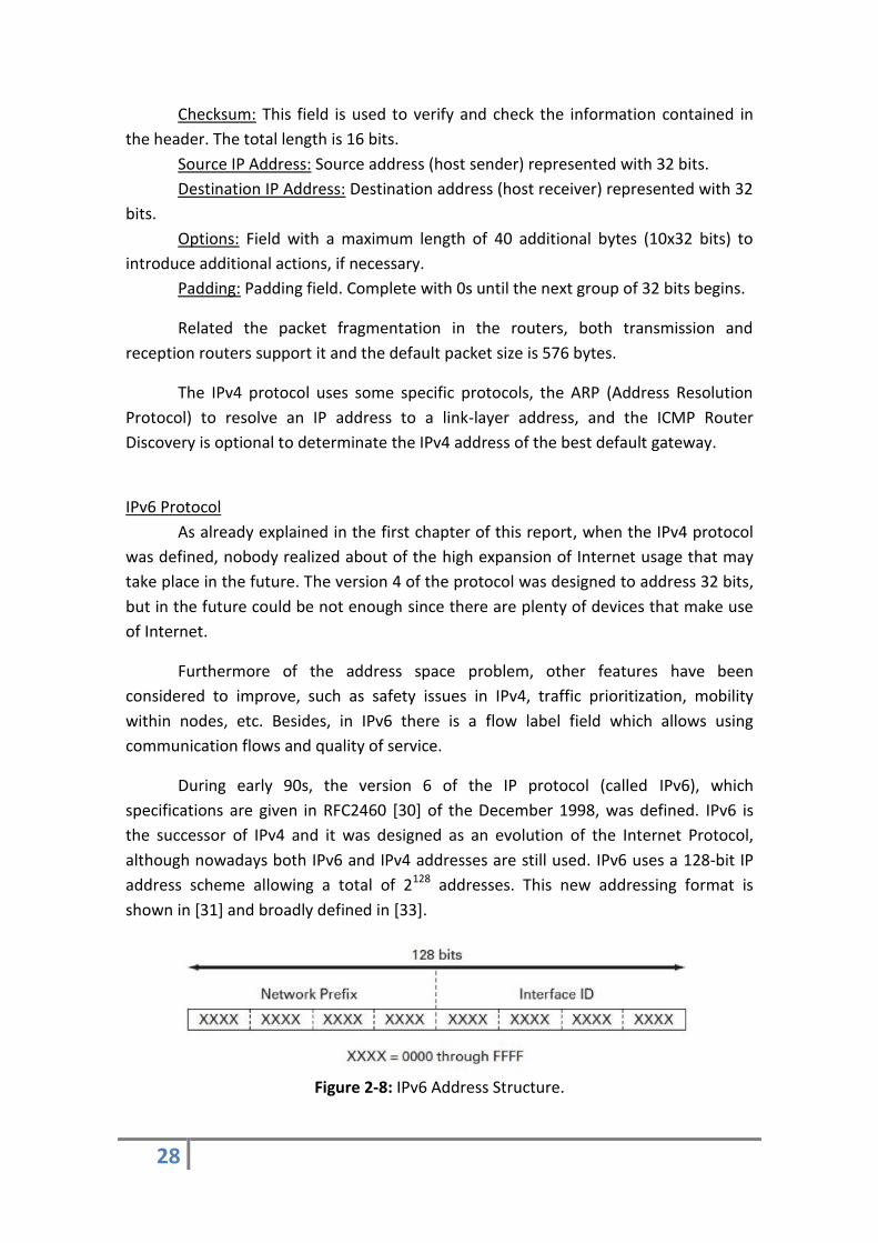
During early 90s, the version 6 of the IP protocol (called IPv6), which
specifications are given in RFC2460 [30] of the December 1998, was defined. IPv6 is
the successor of IPv4 and it was designed as an evolution of the Internet Protocol,
although nowadays both IPv6 and IPv4 addresses are still used. IPv6 uses a 128-bit IP
address scheme allowing a total of 2128 addresses. This new addressing format is
shown in [31] and broadly defined in [33].
Figure 2-8: IPv6 Address Structure.

29
Also in [33], [34], and the updated version of this Request for Comments [35],
different types of IP addresses are described that supports the IPv6 protocol, which are
unicast, anycast or multicast.
Unicast: A unicast address represents a single interface, and therefore the
package is delivered to that single address.
Anycast: The identifier of an anycast address is defined for a set of interfaces
(typically belonging to different nodes). A packet sent to an anycast address is
delivered to one (any) of the interfaces identified by that address.
Multicast: Like the previous case, the identifier is defined for a set of interfaces
(typically belonging to different nodes). However, a packet sent to a multicast address
is delivered to all interfaces identified by that address.
An IPv6 packet also comprises a header section and a data section (data section
maximum is the same as in IPv4). In this case, IPv6 header size increases up to 40 bytes
(20 more bytes than IPv4 header) and it is possible to add optional extension headers
(see the coming comparison section for more detail). The figure 2-9 shows the IPv6
header based on the specifications described in [30] [32].
Figure 2-9: IPv6 header.
In the papers [30], [31], [34] -which is the updated version of [32] and [33]-,
[35] and [36] it is explained in detail all of the fields included In the IPv6 version
header, which are summarized below:
Version: Describes the version of the protocol, in this case the RFC2460 [30]
describes the version 6. This field occupies a length of 4 bits.
Traffic class: Specifies the class of the traffic travelling in the datagram. Values
0-7 are defined for data traffic congestion control and 8-15 for audio and video traffic
without congestion control. 8 bits are needed to store this field.
Flow Label: Flow identifier which consists solely of the combination of a source
address and a label of 20 bits. Thus, the source assigns the same label to all packets
which are part of the same flow. Using this tag (which identifies a path) the network
enables to route instead of routing switch [37].
Payload Length: Contains the number of bits composing the total datagram
header and the number of data. It occupies 16 bits.

30
Next Header: Indicates the type of header which follows the fixed IPv6 header.
It can be TCP / UDP, ICMPv6 or an optional IPv6 header type. This field occupies 8 bits.
Hop Limit: Sets the lifetime which the datagram or the fragment may remain in
the network without being dropped. The aim is to prevent a datagram for travelling all
the time without being intercepted by any end user. The length of this field is 8 bits.
Source IP Address: Source address (host sender) represented with 128 bits.
Destination IP Address: Destination address (host receiver) represented with
128 bits.
Related the packet fragmentation only transmission routers support it (avoiding
the intermediate fragmentation) and the default packet size is 1280 bytes.
The IPv6 uses Multicast Neighbour Solicitation to resolve an IP address to a link-
layer address, and the ICMP Router Discovery is mandatory to determinate the IPv6
address of the best default gateway.
IPv6 compared to IPv4
Once both versions of the protocol have been presented, the features of both
protocol versions can be compared. The most recent version of the protocol (IPv6)
introduces new specifications in order to improve the user experience. It is a difficult
process, since the most of machines that connect everyday around the world to the
Internet are using the version defined more than 30 years ago (IPv4 one). Both headers
are presented again in figure 2-10 extracted from [32], in order to compare all the
fields defined above.
Figure 2-10: Comparative between IPv4 andIPv6 headers [41].
According to the documents and books [37], [38] and [39], the main
functionalities and features of both versions which are different or have been changed
in terms of operation or safety are described below.

31
The most striking difference is the increase in the capability of routing and
addressing. IPv6 increases the IP address size from 32 bits (which use IPv4) to 128 bits
to support more levels of addressing hierarchy and a much higher number of
addressable and simpler auto-configuration of addresses nodes.
Therefore, the number of addresses is between 2^32 addresses which can be
handled at the same time using the IPv4 protocol, to 2^128 which allows IPv6
addressing. Obviously, this feature solves the problem that may appear on the IPv4
address pool system, avoiding the IPv4 address depletion and allotting the unallocated
IPv4 addresses through IP version 6.
Another significant difference is regarding the routing scalability as IPv6
specification does not defined broadcast addresses, this function is replaced by
multicast addresses. All IPv6 interfaces must have at least one unicast address, but a
single interface can also have multiple IPv6 addresses.
The IPv6 header format is much simpler since some IPv4 header fields have
been removed reducing the cost of processing and routing protocol. Even though IPv6
addresses are four times longer than IPv4 addresses, the IPv6 header is only twice
larger than the size of the IPv4 header.
IPv6 introduces the options field which can be used optionally; the extension
header which removes several secondary aspects from the main header and adding
them in this space. Extension headers allow multiple services such as Hop-By-Hop
Options, Routing, Fragment, Authentication Header (AH), Encapsulating Security
Payload (ESP), Destination Options and No Next Header. IPv6 also defines new
extensions and options that provide additional support for authentication, data
integrity and confidentiality as a basic element of IPv6 as described in [40] since IPSec
is mandatory.
A new feature is added to enable the packet labelling when the packet belongs
to a particular traffic flow for which the sender requests special handling, such as non-
default quality of service or real time service, similar to a MPLS tunnel.
As main conclusion, changes are made in terms of addresses assignation as well
as IPv6 header options are encoding allows more efficient forwarding and higher
flexibility to introduce new options in the future.
2.3.2 The transport layer protocols
The transport protocols are rules that define how the information has to be
encapsulated and transmitted. The transport layer provides to the application layer
three services: a connection-oriented protocol TCP service "Transmission Control

32
Protocol", a service and connectionless UDP protocol "User Datagram Protocol" and a
prior agreement STCP protocol “Stream Control Transmission Protocol”.
UDP: The UDP protocol is a transport layer protocol for use with the IP protocol
which provides a service for exchanging datagrams across the network mode best-
effort (the reception of datagrams or packets is not guaranteed since it is not a
connection oriented protocol). The service provided by the UDP protocol is not reliable
because it does not guarantee delivery or some protection to avoid duplication of
packets. The simplicity of UDP packets reduces the amount of information needed to
be used, which makes the UDP protocol the best choice for some applications.
A computer can send UDP packets without establishing a connection to the
device that will receive them. The computer completes the information fields in the
UDP packet headers and sends the data along with the header through the network
layer by the IP protocol.
TCP: The TCP protocol is in charge of fragmenting the information and sending
it safely to end to end extreme, since it is a connection oriented protocol (providing
confirmation of frames received on the receiver side). It is much more secure than UDP
but also requires more processing time to reassemble packets and check if any
intermediate fragment is missing.
SCTP: It is an oriented message protocol (the message may be sent between
two devices without prior arrangement) and much safer than TCP or UDP. It provides
reliability, flow control and sequencing as TCP, but also allows sending messages out of
order as UDP.
Figure 2-11: The transport level protocols.
In the figure 2-11 can be seen the transmission initialization performed safely
using the SCTP protocol, while UDP sends synchronization and keep-alive datagrams
between RNC (172.18.138.93) and the Node-B (172.18.138.92) or vice versa. The TCP
protocol over IP is responsible for transmitting the packets towards internet.
In general, TCP is used when there cannot be loss of data, and UDP is used
when a low amount of information is sent but the packages require high-speed
transfer. Most networks combine the internet protocol (IP) with the higher-transport
level protocol called TCP, which establishes a virtual connection between a destination
and a source.

33
2.3.3 The application layer protocols
The protocols of the application part which are necessary to carry out the
traces analysis are HTTP and DNS.
HTTP: The 1.1 version of this protocol is used in each transaction to or from
Internet. The purpose is to allow HTTP file transfer between a browser (client) and a
web server. It is also used to load images, videos or other content available on the
webpages.
DNS: The Domain Name Server is a distributed database, a system which
contains information that is used to translate domain names (easy to remember by
people as for example www.domain.com) to an internet protocol (IP) numbers which
is the easiest way that machines can be found in internet each other.
Figure 2-12: HTTP and DNS protocols in Whireshark.
2.4 UMTS performance on the internet network
After explaining the protocols involved both in establishing connection
(signalling protocols) and in the data exchange (TCP / IP protocol stack), this section
introduces the protocol operation over the UMTS network.
Firstly, the process of establishing the connection and the IP tunnelling for data
transmission are explained. After, a brief description of IPv6 protocol optimization on
mobile devices is presented.

34
2.4.1 Protocol operation in UMTS architecture
IP tunnelling call setup
To fully understand the signalling protocols explained in the section 2.2 of this
report, it is necessary to understand how the authentication process is performed on
the device and how the network creates an IP tunnel ensuring the navigation.
When the device is turned on, it sends a request to attach to the network. In
the figure 2-13 is shown the sequence over the RANAP protocol (datagrams between
the RNC and the SGSN) where can be seen an initial attach request message. The core
part receives the message and after some authentication operations, solve the attach
request accepting and completing it.
Figure 2-13: Attach to the network.
Once the device is attached on the network, it sends a service request to apply
for web service and the network activates the PDP context assigning the IP address to
the user.
Figure 2-14: PDP Context Activation.

35
When the device applies the webpage, the request is sent to the DNS which
responses with the domain in IP address format. To forward the query and response
messages correctly, the routing table must be configured on the gateway router. The
phone is able to navigate and load a webpage.
Figure 2-15: DNS query and response.
The device is turned off, thus the RNC requests the detach from the network
and the PDP context is deleted. The GTP tunnel is closed as well.
Figure 2-16: Detach request.
To perform these operations, the device and some parts of the network have to
be prepared for both versions of the protocol. The request to open the PDP context is
performed by the device in IPv4, IPv6 or Dual Stack (the connection has to be
established either in IPv4 or IPv6). Therefore, the device and the SIM card must be
configured to work with the appropriate version of the protocol. In the network, the
equipment responsible for processing the Activate PDP context request is the SGSN (as
can be seen in the figure 2-17), thus it must also be correctly configured [42].
Figure 2-17: PDP context activation.
36
The control operations discussed above opens the PDP context creating an IP
tunnel transport over the GTP protocol between the device and the GGSN to transmit
data.
The IP tunnelling provides numerous advantages to the communication such as
more secure transmission, easier traffic encapsulation over another protocol or
multiprotocol interconnection of local networks. In addition, the IP tunnel provides a
means to transport data packets between elements which operate over the same
protocol, but the intermediary network does not support it. The IP tunnel creates a
virtual link between two nodes that can be accessed by IP, thus the link can be used to
carry IPv6 packets between two IPv6 sites but through the IPv4 network.
The IP-based network offers an architecture suited for supporting the rapidly
growing mobile data and multimedia services providing the successful Internet service
and mobile paradigm to users integrating seamlessly with the Internet.
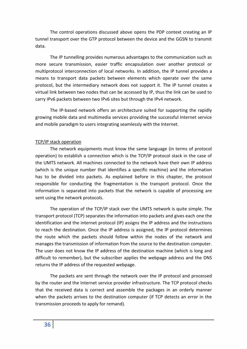
TCP/IP stack operation
The network equipments must know the same language (in terms of protocol
operation) to establish a connection which is the TCP/IP protocol stack in the case of
the UMTS network. All machines connected to the network have their own IP address
(which is the unique number that identifies a specific machine) and the information
has to be divided into packets. As explained before in this chapter, the protocol
responsible for conducting the fragmentation is the transport protocol. Once the
information is separated into packets that the network is capable of processing are
sent using the network protocols.
The operation of the TCP/IP stack over the UMTS network is quite simple. The
transport protocol (TCP) separates the information into packets and gives each one the
identification and the internet protocol (IP) assigns the IP address and the instructions
to reach the destination. Once the IP address is assigned, the IP protocol determines
the route which the packets should follow within the nodes of the network and
manages the transmission of information from the source to the destination computer.
The user does not know the IP address of the destination machine (which is long and
difficult to remember), but the subscriber applies the webpage address and the DNS
returns the IP address of the requested webpage.
The packets are sent through the network over the IP protocol and processed
by the router and the Internet service provider infrastructure. The TCP protocol checks
that the received data is correct and assemble the packages in an orderly manner
when the packets arrives to the destination computer (if TCP detects an error in the
transmission proceeds to apply for remand).

37
2.4.2 Web optimization for IP protocol in UMTS
As discussed in the introduction, a few years ago experts were thought that the
IP address space is going to end very soon due to the progressive increase of internet
devices. Therefore, the major telecom operators and regulators began to push
manufacturers and network providers to fully support the IPv6 protocol.
Developers and network’s manufacturers had to start optimizing their services
such as applications, websites and digital services, etc., and not only to support the
IPv6 protocol, but optimizing the number of packets needed to ensure the operation
or service (i.e. number of ack / get messages involved in the datagram’s flow), as well
as the number of signalling messages through the network or the web load time.
Google has developed several improvements in the implementation of the IPv6
protocol such as optimizing of transport efficiency between a mobile node and a
correspondent node in a mobile IP network [43] or optimizing the authentication
enabling mechanism [44], among many others.
During the most recent years, experts have realized that the problem with IPv4
is not so serious (currently the number of IPv4 addresses has not ended), and the
optimization process is taking place more slowly than originally planned. This is the
reason that today, there are a large number of pages that are not able to load when
the request travels encapsulated via TCP over IPv6 protocol, while others are just able
to navigate more slowly than when the request and DNSs are used under IPv4
technology premises. The developers of the most commercial webpages or services as
Google or Facebook are those who have made a greater effort to optimizing, thus the
service should work better that webpages or applications with less number of network
resources (i.e. Signalling, IP Data, etc.).

38

39
Chapter 3
Testbed implementation
In this chapter the testbed architecture and configuration are described. In
addition, both scenarios are introduced, the first on consists of testing phone features
related web browsing and the second one, which focuses on the most common
applications. To end the chapter, the KPIs that have been measured are detailed.
3.1 Testbed environment
Once a study has been made about the necessary theory and state of the art,
the first step in the lab is to analyse the elements of the testbed network and configure
all of them properly. The laboratory is modelling as the UMTS network, formed as the
RAN (Node B, RNC) and the Core (SGSN, GGSN). In addition, the network has the HLR
element which is responsible for managing user permissions and authentication
thereof (as is described in 2.1.2 section). The scheme of the network layout can be
seen in the next figure.
Figure 3-1: Laboratory layout.

40
As described in the introduction chapter, the aim of the measurements made in
the testbed is to know how the devices behave in a network configured in the same
manner as the real network. The goal is to measure the impact generated by the
interactions made on the device, but using a specific network for this project in order
to avoid possible interference (which may appear on the real network due to the big
number of users who connect simultaneously to the network).
Actually, the core part of the network belongs to the real network (since the
addressing space is enough to cover real and testing devices), but the radio network
(Node-B and RNC) only provides coverage to our testbed, thus the testing is made over
this specific network avoiding the interference from other networks or other devices
that may change the value of the results.
We are going to test web browsing and application services to measure
representative KPIs such as the IP data volume and the radio signalling. We are going
to measure web load time (for browsing tests) and battery consumption (for apps
tests) as well, but the most interesting KPIs in the context of the project are related to
the consumption of network resources. These KPIs have chosen because they give us
information about the message signalling load through the network depending on the
IP protocol used, and the amount of data exchanged getting access to the same
service.
To measure and analyse these two KPIs, we are going to use two computers
configured with the necessary tools to collect the trace. The first equipment has a tool
called Wireshark installed and is connected directly between the GGSN and the
Internet (view previous image) to measure the IP data generated by the website or
application using Wireshark. The second computer contains an application of wireless
technology (proprietary from the network vendor) and is directly connected to the
RNC for measuring all messages traversing the radio part (figure 3-1).
The configuration used in the laboratory corresponds to the UMTS network
described in chapter two, and the output towards internet is performed using either
IPv4 or IPv6. The parameters of the testbed network and the radio timers are set with
the same value as the real network. The HLR (containing all subscribers who can access
the service) and DNS servers belong to the real network and provide the web service in
the same way that the real network in order to obtain the most reliable results. The IP
configuration also corresponds with the real network in order to check if the real
network really supports all services under IPv6 operation.
This configuration is good for achieving the objectives of the project since the
UMTS network is much optimized to support the internet services, and also to provide
updated information since this technology is the most used currently (the LTE
technology is still under deployment in Spain).

41
3.1.1 Steps of the testbed deployment
To verify that the network is performing properly, the testing phase has used
devices that support both versions of IP protocol. These devices are pre-installed with
different operating systems to ascertain the impact which is generated according to
both, the network protocol and the operating system development on the network.
Besides, all devices have also been configured with web browsers and applications to
meet the needs of different scenarios. The configuration of IPv4 and IPv6 scenarios has
required considerable effort in terms of setting up the environment.
The first step consists of checking the connectivity between different elements,
especially between radio and core parts. All equipments must have their own unique
address (both MAC and IP) to create the PDP context and attach phones to the
network correctly. Since the lab had been closed for many months, it has been
necessary to check the expiration of licenses and parameters configuration. Some
connectivity problems have appeared which are mainly caused by the expiration of the
operating license of any equipment or by collisions related to IP configuration when
new elements are installed and configured on the network.
Once connectivity is working properly, the phone is able to attach to the
network and create the PDP context; the GGSN assigns an IP address to the device
which is mandatory for getting access to internet services and navigation (see chapter
two for more details). The next phase is to verify that the network can provide service
as well (since the fact that a device has IP address assigned is not enough), but the DNS
should work and the transmission to and from internet must be configured correctly.
The IPv4 and IPv6 DNSs available have been reviewed and configured for the testing,
and the routing tables of the routers.
When all configuration steps have been made, the test plan previously
scheduled can be performed. The final step is consists of evaluating the results which
are going to be measured analysing the traces of all tests using Wireshark. This
application allows monitoring each one of the packets traversing over the network. As
described above, the protocols which are used during the laboratory work are split in
parts according to: signalling protocols (RRC, NBAP, RANAP) and network protocols
(HTTP, DNS, TCP and IP).
3.1.2 Problems and Issues solved
Once presented the network environment which we will use, in this part of the
report are described the most important issues which have appeared during the
testbed setup. In spite of several setbacks have appeared, the setup phase has been
finished successfully solving all the problems which have arisen.
42
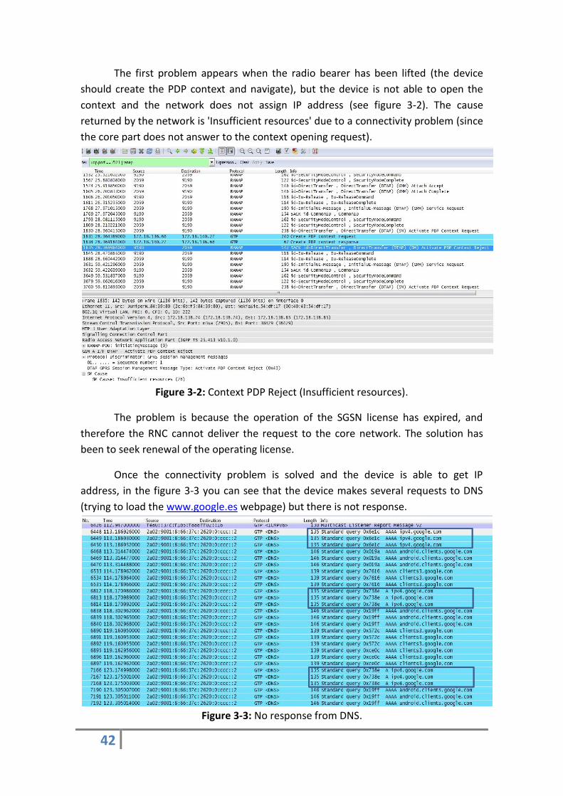
The first problem appears when the radio bearer has been lifted (the device
should create the PDP context and navigate), but the device is not able to open the
context and the network does not assign IP address (see figure 3-2). The cause
returned by the network is 'Insufficient resources' due to a connectivity problem (since
the core part does not answer to the context opening request).
Figure 3-2: Context PDP Reject (Insufficient resources).
The problem is because the operation of the SGSN license has expired, and
therefore the RNC cannot deliver the request to the core network. The solution has
been to seek renewal of the operating license.
Once the connectivity problem is solved and the device is able to get IP
address, in the figure 3-3 you can see that the device makes several requests to DNS
(trying to load the www.google.es webpage) but there is not response.
Figure 3-3: No response from DNS.

43
It looks like a configuration problem with the router tables since the query is
properly received and processed by the DNS, but once the domain name server has
performed the translation of the address, it cannot send the response to the network
because the gateway router does not know the route back to the Node-B.
We had to review the back routes (using the command show ipv4/ipv6 route)
to check that everything is correctly configured. Indeed, the router has not set the
path back to the testbed, it is able to route packets to outside the network but not
return (from outside to the radio part). Once fixed the problem there is DNS response
as can be seen in the figure 3-4 (standard query response).
Figure 3-4: Standard query response from DNS.
After solving the problem of connectivity and DNS configuration, the phone is
attached to the network and with the DNS server properly configured. However, in
some cases the network is not able to provide any service. To solve this problem, we
have had to contact the manufacturer of the devices and the operating systems
developers to upgrade the smartphone to the latest firmware version available.
Figure 3-5: Service no subscribed.
Some devices have been configured with previous versions of the operating
system that did not support IPv6 laboratory scenario. The manufacturer has been the
responsible for solving this problem.

44
To end this section, we should mention another problem, the observation of
anomalous and unprecedented situation. The normal procedure should be that the
RNC asks periodically to the device for a packet (called 'cell update') indicating whether
the device is still connected and under what conditions when the device is in idle
mode. The RNC receives this packet and keeps the connection open, otherwise it sends
an IU-release datagram to release the radio resources and interrupt the
communication.
However, it has been observed in some tests that the device sends the cell
update but it never comes to be received by the RNC, so this one sends the IU- release
and the phone is disconnected. This problem has requested an analysis in depth, since
each time the mobile is disconnected, it requests a new attach and a new creation of
the PDP context, generating an increase in both the radio signalling and the number of
IP packets that are exchanged with Internet cloud. As mentioned, this issue is complex
and it does not have a trivial solution because the device and the RNC work perfectly
(the device sends the message and the RNC and if the RNC does not receive it, send
the radio link release). After several weeks taking traces on all interfaces, we have
discovered the source of the problem, disconnect are produced by interferences
coming from equipments placed at other contiguous laboratory, in particular the cause
is some small-cells that were recently installed and working in the same uplink band
that the UMTS connection.
The GGSN activates the PDP context and assigns the IP address to the user.
Figure 3-6: IP Address assignation.
The device sends a service request indicating that there is not active context. As
a result, the SGSN deletes the old PDP context and the GGSN activates a new one.
Figure 3-7: Delete PDP context and new activation.
The solution has been to use a RF box to prevent other interfering signals that
may be in the lab.

45
3.2 Scenario 1: Web Browsing
The first of these scenarios consists of analysing the behaviour of devices and
operating systems when different versions of webpages are loaded. It is important to
measure the performance of webpages which can be loaded on a phone to see if they
are really optimized for both protocols. For this purpose, the plan is to open two
different websites and compare the IP data consumption, signalling and web load time
between IPv4 and IPv6. The detailed KPIs which are interesting to measure are
described in the point 3.4 of this chapter.
To make the web browsing test we have chosen two different webpages to
compare the values of the selected KPIs: www.google.com and www.kame.net.
Google webpage has been chosen because it is the most used search engine in
the world and the servers pursuing large amounts of traffic. Besides, it is also a page
that most users know and can use later. It is expected that the company continuously
optimizes and improves security and functionalities supported. According to Google's
website (http://IPv6test.google.com), the webpage is prepared to work with the IPv6
protocol.
The webpage of kame is operated by a project supported by six companies in
Japan to provide a free stack of IPv6 and Mobile IPv6. This webpage has been chosen
since it shows the dancing kame when IPv6 HTTP is used. The user should be able to
see the turtle moving if the page loads correctly over IPv6 protocol.
The methodology of this test consists of selecting the web browser which is
pre-installed by default in the operating system (just in case of have more than one
stored in the device) and remove cookies, formularies and history of web browser.
Once the browser is ready, write the page address in the URL bar and wait until the
page is completely loaded to measure the KPIs.
3.3 Scenario 2: Apps
The purpose of this scenario consists of analysing the behaviour of applications
on the device when different interactions with the application are made. It is
important to measure the performance and behaviour of the applications which can
be installed on a phone to see if they are really working through both version of the
protocol. For this goal, the plan is test some applications and to compare some KPIs
which are interesting to measure (described in the point 3.4 of this chapter).

46
The applications which have been selected are the most used by users
according to several studies conducted during 2013 [45] [46]: Facebook Messenger,
Facebook, Google Maps and Youtube.
To set the scenario the phone is switched on and the IPv4/IPv6 APN (Access
Point Network) is selected. Then, the desired application to measure is installed and
the phone is turned off. Once carried out the set-up process, the test consists of
interact with the application (sending streams, audio or video) according the table 3-1.
Applications Test Plan
FB Messenger
- Send string "hello", wait 2 minutes - Receive string "hi, how are you?", wait 2 minutes - Answer again “I am fine thanks”, wait 2 minutes - Repeat these steps 3 times.
- Share the message “hello, we are testing this app”, wait 2 minutes. - Upload a picture, wait 2 minutes. - Upload a video, wait 2 minutes. - Repeat these steps 2 times.
Google Maps
- Update the current location - Look for Madrid (Spain) city in Maps. - Get indications to go to Stockholm (Sweden).
Youtube
- Look for ‘Movistar’ in the browser. - Load and watching the first video (advertising on Movistar and Spanish team of football)
Table 3-1: App testing.
3.4 KPIs measured
At this point, the KPIs (Key Performance Indicators) measured are described
paying particular attention on the fact that why they are important, what kind of
interactions or effects of input parameters are expected and how they are going to be
evaluated.
We are going to measure IP Data (Number of IP packets and total length) and
RNC Signalling of each one of the selected applications and web browsing tests, the
load time of webpages for browser tests and the battery consumption for apps. The
most important KPIs form the network side, IP data and signalling, have chosen
according to the different domains of the network. On the radio side, we are going to
analyse the impact on the base station RNC in terms of signalling and the total size of
the data transmitted encapsulated over the IP protocol in the core part.
The load time does not make sense for applications, since the applications are
pre-installed in the phone and the booting process takes a few seconds. The battery

47
has been only measured in tests related to applications, since the browsing tests are
much shorter (just during the time which the device takes to carry the load of the
web), and it is difficult to appreciate significantly the battery power consumed.
3.4.1 KPIS for browsers and apps
IP data and number of IP packets
This KPI is probably the most interesting to measure as it provides information
on both the number of packets and the length thereof exchanged with Internet. This
KPI is measured using the Wireshark tool connected to the output of the GGSN, as you
can see in the diagram of the figure 3.1.
Figure 3-8: Whireshark Interface for End-Points
Figure 3-9: IP data measurement.

48
This KPI counts all packets that are transmitted over IP protocol having as
source an IP address assigned to the device and as destination an IP address of the
Internet or vice versa.
Surely, this KPI should vary significantly according to the version of the protocol
used which is the reason to consider it also interesting in the vicinity of this master
thesis as it provides an insight into the efficiency of both the device and the network.
RNC signalling
It consist of measuring the signalling (information exchange within the control
plane) required by the device to connect and to keep it active (using keep-alives
messages). By measuring this field on the RNC, it ensures that the total number of
signalling messages is measured, since all the flow of communication between the
device and the Internet necessarily goes across the RNC.
The test measurement process is going to use a software connected to the RNC
output to measure the number of signalling messages such as RRC messages, NBAP
messages, RLC messages, RANAP messages, Rab established, rrc-state indicator
cell_FACH, rrc-stateindicatorCELL_PCH, rrc-stateindicatorURA_PCH, Transition-to-
cell_fach and signalling connection release (see the protocols which have been
discussed in the section 2.2).
Figure 3-10: RNC signalling measurement.

49
It is important to note that the number of signalling messages may vary
significantly depending on the duration of the test due to a higher number of messages
are sent to keep the connection open (keep-alives) if the test lasts a longer time.
This field is important since it provides information about the total number of
messages required to maintain a data connection open, either using the IP protocol
version 4 or version 6.
3.4.2 Browser KPIs
Web Load time
The time needed to load completely the website is represented by this KPI. This
measurement is delivered in seconds and is obtained from the timekeeper.
This value comprises the time since the device generates the webpage request
until the device loads the complete webpage. During this interval the request is sent to
the DNS, which translates the name of the webpage into the IP address, and responses
to the device with this requested IP address. Once the name is known, the response is
sent to the appropriate server which loads the requested webpage.
It is good to know if the IPv6 really reduces the loading time of a website or not
(theoretically there is not intermediate fragmentation in IPv6 thus there is not
reassembly time).
3.4.3 Applications KPIs
Battery power
Measuring the level of battery is important for the user and the device. We
want to know if any application consumes more battery according to the IP version
used, or if the IP protocol helps to improve the battery life.
To measure the battery, it has been used an equipment called power
management consisting of positive and negative poles to connect to the device battery
gap (where the battery should be introduced). This element is responsible for
supplying the necessary power consumption as well as to monitor the percentage of
required energy. There are some devices where the battery is fully integrated with the
phone and it is not able to use this machine; in these cases it has been used an
application available on the market called Battery that provides the same value.
This KPI show if the protocol is involved in the battery consumption or if the
battery level consumed is independent of the IP protocol version.

50
3.5 Expected results
This section describes briefly the expected behaviour in each of the KPIs
measured. The aim is to know the expected behaviour of both versions of the protocol
and compare them with test results although the results may be different depending
on the webpage loaded, the applications or the operating system.
Due to the size of IPv6 headers (as discussed above is 20 bytes higher), it is
expected that the data exchanged using IPv6 is higher. Although the consumption of IP
data depends on the optimization that has made by the manufacturer on the device,
make a request to the DNS and load the same website or interact with one application
on IPv4 and IPv6 should generate more traffic when the IPv6 protocol is used
(depending on the number of packets since each fragment carries its own header).
In the case of RNC signalling, the expected result is that signalling should be
lower on IPv6 tests, since the newer version of the protocol is more optimized. This is
caused since experts have been working too many years in the protocol design and
implementation, using acquired experience to eliminate unnecessary signalling
messages (to consume less resources) despite of the establishment messages are the
same to open connection at radio level.
In terms of web load time (for browser tests), which means the time required
to fully load a webpage, the time in seconds should be less in IPv6 since there is not
fragmentation at intermediate routers and therefore no packet reassembly time,
reducing the overall load time of the page.
The battery power consumed during applications testing should be similar
because the device performs the same number of operations regardless of the
network protocol used.
According to the expected behaviour, the signalling in IPv6 should be less (using
less battery), but more data are generated in IPv6 (increasing the battery power
consumption) thus the power consumed should be the same.
Therefore, although the IP generated data are slightly higher in IPv6 than in
IPv4, the expected behaviour of the IPv6 protocol is better since the signalling in the
network is less and therefore the radio part is less overloaded. In addition, the time
required to perform the same operation (such as loading a web page) is lower
improving the user experience.

51
However the obtained results may be different to the expected ones during the
previous analysis in this section. One device may behave in a different way with as
expected with a single webpage or application, and otherwise behaves normally in all
other cases (see the coming comparison section 4.3).

52

53
Chapter 4
Performance Evaluation
In this chapter all results are presented, both in format table and in graphical
one. Several tests were performed for each one of the operating systems ensuring the
viability of the results since the behaviour of the system is stochastic, thus the tests
with the same configuration have been repeated several times.
Specifically, we have repeated 25 times each test with the same configuration,
that is, 25 identical tests for all devices in which ones the KPIs are measured as
described in the previous section (IP data volume, RNC signalling, load time for
browsing and battery for apps). To be able to establish a comparative we have used
several devices with different operating system such as operating system 1, operating
system 2 and operating system 3 (the name cannot be revealed due to the
confidentiality agreement).
After obtaining the results, we have calculated the average to graph it and draw
proper conclusions. That is, the results given below represent the average of the
values obtained during the 25 tests performed.
To ensure that the results are reliable, we have calculated the confidence
interval for the average according to the Microsoft specification [47] using Microsoft
Excel. The syntax of the function in Excel is CONFIDENCE(alpha, standard_dev, size)
where the alpha value means the confidence level which is equals to 100*(1 - alpha) %.
We have checked the results and they match the interval of confidence using an alpha
of 0.05, which indicates a 95 percent of confidence level.
4.1 Browser Results
In this section are detailed the browser test results.
4.1.1 Data Volume
This section presents the results of data volume (both, number of IP packets
and total length) measured through Wireshark. Two different graphics are shown, one
for the webpage of Google and other one related to the webpage of Kame.
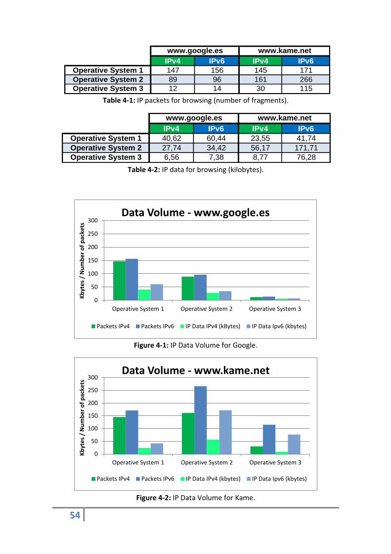
54
Table 4-1: IP packets for browsing (number of fragments).
Table 4-2: IP data for browsing (kilobytes).
Figure 4-1: IP Data Volume for Google.
Figure 4-2: IP Data Volume for Kame.
IPv4 IPv6 IPv4 IPv6
Operative System 1 147 156 145 171
Operative System 2 89 96 161 266
Operative System 3 12 14 30 115
www.kame.netwww.google.es
IPv4 IPv6 IPv4 IPv6
Operative System 1 40,62 60,44 23,55 41,74
Operative System 2 27,74 34,42 56,17 171,71
Operative System 3 6,56 7,38 8,77 76,28
www.google.es www.kame.net
0
50
100
150
200
250
300
Operative System 1 Operative System 2 Operative System 3
Kb
yte
s /
Nu
mb
er
of
pac
kets
Data Volume - www.google.es
Packets IPv4 Packets IPv6 IP Data IPv4 (kBytes) IP Data Ipv6 (kbytes)
0
50
100
150
200
250
300
Operative System 1 Operative System 2 Operative System 3
Kb
yte
s /
Nu
mb
er
of
pac
kets
Data Volume - www.kame.net
Packets IPv4 Packets IPv6 IP Data IPv4 (kbytes) IP Data Ipv6 (kbytes)

55
As expected, the IP data generated to access the same website are more over
the IPv6 protocol than IPv4 one (between 5% and 30%). This is mainly due to the size
of the headers, which occupies more bits in IPv6 than in IPv4 header (20 bytes more
for each packet as described on page 29 of this report).
Moreover, from the www.google.es results we can conclude that the operating
systems two and three generate less traffic when loading the webpage. However,
when loading the website www.kame.net, IPv6 traffic increases significantly, because
it is a very small website and the owners probably have fewer resources than Google
enterprise.
As we can seen, the operating system one generates more or less the same
amount of IP data in both webpages, and operating systems two and three work worse
in kame webpage than google one.
4.1.2 RNC Signalling
This section presents the results of signalling measured on the base station
(RNC). Two different graphics are shown, one for the webpage of Google and other
one related to the webpage of Kame.
Table 4-3: RNC Signalling for browsing (number of messages).
Figure 4-3: RNC signalling for Google.
IPv4 IPv6 IPv4 IPv6
Operative System 1 24 19 24 18
Operative System 2 22 19 25 18
Operative System 3 22 18 20 17
www.google.es www.kame.net
0
5
10
15
20
25
30
Operative System 1 Operative System 2 Operative System 3
Nu
mb
er
of
sign
allin
g m
ess
age
s
RNC Signalling - www.google.es
IPv4 IPv6

56
Figure 4-4: RNC signalling for Kame.
In terms of signalling the results are quite stable. As expected, the number of
messages involved in the access radio part is similar regardless of protocol.
As can be seen, the signalling in IPv4 is slightly larger than IPv6 because IPv6
protocol design is more recent and requires less number of RNC messages to load a
webpage (it is important to consider that the browsing is done in a short time, so that
there are not keep-alive messages).
4.1.3 Web load time
This section presents the results of browsing load time (the total time required
to fully load webpage). As in the previous sections, there are two different graphics:
the webpage of Google and the webpage of Kame.
Table 4-4: Load time (seconds).
0
5
10
15
20
25
30
Operative System 1 Operative System 2 Operative System 3
Nu
mb
er
of
sign
alin
g m
ess
age
s RNC Signalling - www.kame.net
IPv4 IPv6
IPv4 IPv6 IPv4 IPv6
Operative System 1 5,58 3,85 24,56 21,92
Operative System 2 2,87 1,65 19,27 13,00
Operative System 3 1,52 1,14 13,98 9,50
www.google.es www.kame.net

57
Figure 4-5: Load time for Google.
Figure 4-6: Load time for Kame.
As expected, the time required to fully charge a webpage is higher in IPv4 than
in IPv6.
The load time graphics confirm that the kame website is less optimized that
Google, as the same request page takes to load between 10 and 15 seconds more
depending on the device and the operating system. In addition, it is confirmed that
operating systems two and three are optimized and take less time to fully load the
page that operating system one (regardless of the protocol used).
0
5
10
15
20
25
Operative System 1 Operative System 2 Operative System 3
Seco
nd
s
Web load time - www.google.es
IPv4 IPv6
0
5
10
15
20
25
Operative System 1 Operative System 2 Operative System 3
Seco
nd
s
Web load time - www.kame.net
IPv4 IPv6

58
4.2 Apps Results
In this section are detailed the applications test results. We have also tried
other common applications such as Whatsapp, Skype or Twitter but none of them
supports the IPv6 protocol (see table 4-8 in section 4.3).
4.2.1 Data Volume
This section presents the results of IP data volume measured through
Wireshark. Four different graphics are shown, one for each of the tested applications.
Table 4-5: IP Data for apps (Kilobytes).
Figure 4-7: IP data for Facebook Messenger.
Figure 4-8: IP data for Facebook.
IPv4 IPv6 IPv4 IPv6 IPv4 IPv6 IPv4 IPv6
Operative System 1 393,41 485,47 5150,02 7817,03 4393,47 6343,72 7383,99 17458,28
Operative System 2 411,63 748,23 10384,97 18246,94 - - 8306,35 25317,96
Operative System 3 - - 876,69 9751,21 - - 4087,72 15389,23
Facebook Messenger Facebook Google Maps Youtube
0
100
200
300
400
500
600
700
800
Operative System 1 Operative System 2 Operative System 3
kilo
byt
es
IP data - Facebook Messenger
IPv4 IPv6
0 2000 4000 6000 8000
10000 12000 14000 16000 18000 20000
Operative System 1 Operative System 2 Operative System 3
kilo
byt
es
IP data - Facebook
IPv4 IPv6
It does not support
Facebook Messenger
over IPv6.

59
Figure 4-9: IP data for Google Maps.
Figure 4-10: IP data for Youtube.
The applications, like the browsing, also generate more data because IPv6
header is larger than IPv4 one. There is a difference depending on the operating
system being the OS two the worst in this case.
4.2.2 RNC Signalling
This section presents the results of signalling measured on the base station
(RNC). Four different graphics are shown, one for each one of the tested applications.
0
1000
2000
3000
4000
5000
6000
7000
8000
Operative System 1 Operative System 2 Operative System 3
kilo
byt
es
IP data - Google Maps
IPv4 IPv6
0
5000
10000
15000
20000
25000
30000
Operative System 1 Operative System 2 Operative System 3
kilo
byt
es
IP data - Youtube
IPv4 IPv6
They do not support
Google Maps over IPv6

60
Table 4-6: RNC Signalling for apps (number of messages).
Figure 4-11: RNC Signalling for Facebook Messenger.
Figure 4-12: RNC Signalling for Facebook.
IPv4 IPv6 IPv4 IPv6 IPv4 IPv6 IPv4 IPv6
Operative System 1 802 550 1161 934 427 284 414 361
Operative System 2 799 550 1290 902 - - 517 474
Operative System 3 - - 1053 677 - - 512 429
Facebook Messenger Facebook Google Maps Youtube
0
200
400
600
800
1000
1200
1400
Operative System 1 Operative System 2 Operative System 3
Nu
mb
er
of
sign
allin
g m
ess
age
s
RNC Signalling- Facebook Messenger
Ipv4 IPv6
0
200
400
600
800
1000
1200
1400
Operative System 1 Operative System 2 Operative System 3
Nu
mb
er
of
sign
allin
g m
ess
age
s
RNC Signalling- Facebook
IPv4 IPv6
It does not support
Facebook Messenger
over IPv6.

61
Figure 4-13: RNC Signalling for Google Maps.
Figure 4-14: RNC Signalling for Youtube.
As explained in the previous chapter, this KPI measures all messages passing
through the RNC since the phone is turned on until it is turned off thus the value
includes both, connection establishment messages and keep-alives.
Therefore, the variations observed in the signalling when comparing one
application with another are not caused by the application itself, but it is because of
the duration of the each test is different (Facebook test time is around twenty minutes
and Google Maps or Youtube is around five minutes).
The signalling also behaves stably in applications and it is again slightly higher in
IPv4 than in IPv6.
0
200
400
600
800
1000
1200
1400
Operative System 1 Operative System 2 Operative System 3
Nu
mb
er
of
sign
allin
g m
ess
age
s
RNC Signalling - Google Maps
IPv4 IPv6
0
200
400
600
800
1000
1200
1400
Operative System 1 Operative System 2 Operative System 3
Nu
mb
er
of
sign
allin
g m
ess
age
s
RNC Signalling - Youtube
IPv4 IPv6
They do not support
Google Maps over IPv6

62
4.2.3 Battery consumption
This section presents the results of the battery consumption. Four different
graphics are shown, one for each of the tested applications.
Table 4-7: Battery for apps (percentage consumption).
Figure 4-15: Battery consumed by Facebook Messenger.
Figure 4-16: Battery consumed by Facebook.
IPv4 IPv6 IPv4 IPv6 IPv4 IPv6 IPv4 IPv6
Operative System 1 2% 2% 3% 3% 1% 1% 1% 1%
Operative System 2 2% 2% 3% 3% - - 1% 1%
Operative System 3 - - 2% 3% - - 1% 1%
Facebook Messenger Facebook Google Maps Youtube
0,00%
0,50%
1,00%
1,50%
2,00%
2,50%
3,00%
3,50%
4,00%
Operative System 1 Operative System 2 Operative System 3
Pe
rce
nta
ge
Battery - Facebook Messenger
Ipv4 IPv6
0,00%
0,50%
1,00%
1,50%
2,00%
2,50%
3,00%
3,50%
4,00%
Operative System 1 Operative System 2 Operative System 3
Pe
rce
nta
ge
Battery - Facebook
IPv4 IPv6
It does not support
Facebook Messenger
over IPv6.

63
Figure 4-17: Battery consumed by Google Maps.
Figure 4-18: Battery consumed by Youtube.
All applications consume about the same battery regardless the protocol
version used, thus we can conclude that the operations performed by the device are
the same (thus the battery consumption is similar).
Facebook has a higher consumption (around 3%) because the interaction is
made with images and videos; while Google Maps and YouTube consume less battery
(1%) because the test has only been done once (actions with Facebook have been
repeated several times).
0,00%
0,50%
1,00%
1,50%
2,00%
2,50%
3,00%
3,50%
4,00%
Operative System 1 Operative System 2 Operative System 3
Pe
rce
nta
ge
Battery - Google Maps
IPv4 IPv6
0,00%
0,50%
1,00%
1,50%
2,00%
2,50%
3,00%
3,50%
4,00%
Operative System 1 Operative System 2 Operative System 3
Pe
rce
nta
ge
Battery - Youtube
IPv4 IPv6
They do not support
Google Maps over IPv6

64
4.3 Analysis of the results
All results which have been measured depend on the optimization of the IP
protocol and the integration thereof with the browsers and the design of each one of
the applications. As described at the end of the chapter two, developers of
applications and websites, as well as mobile operating system manufacturers are still
improving the implementation of IPv6 protocol, thus certain services may operate
worse than expected or even not work.
Applications Work over IPv4 Work over IPv6
(Disabled by default)
Table 4-8: Applications operation over IP.
Except for some applications which do not work over the IPv6 protocol such as
Whatsapp, Twitter, Skype or Yahoo mail (see table 4-8), the results mostly agree with
the expected ones (section 3.5).
The size of the generated IP data is always higher in IPv6 since the header of
the IPv6 protocol is larger than IPv4 and it may depend on the application. However,
the signalling is lower in IPv6 because some work has been done in the design and
optimization of the protocol (eliminating unnecessary radio connection establishment
messages).
Regarding the loading time of webpages, the obtained results can also be
compared with the expected results; the loading time in seconds is lower over IPv6
mainly because there is not packet reassembly reducing the total time required to load

65
the page entirely. As for the battery, as expected, the power consumption is almost
the same using the same service, regardless of the protocol version used.
To end this section, the results depend on the optimization efforts that have
made by manufacturers and developers. The webpage of Google is more optimized
than Kame (see final section of chapter 2) because the amount of IP data generated
are lower when the request is made to Google's servers, as well as the time required
to load the website.

66

67
Chapter 5
Conclusions and future
work
This chapter describes a general conclusion based upon the work done during
this thesis project and provides suggestions for next steps in order to continue the
work. The intention of this chapter is to point out the most relevant ideas of the thesis
and then consider how to build upon them in future researches.
5.1 Conclusions
This section includes findings and recommendations concerning the results
obtained in the laboratory, and also about the IPv6 protocol and its implementation in
the devices and web services.
The conclusions are mainly related to the services which have been tested
(webpages and applications) and the performance on the network resources
consumption. However, there are also important conclusions related IP optimization
and operating system operation. Performing the same action in two different devices
does not carry the same consequences over the network (see end of chapter 2 for
more information).
The most important conclusion which can be drawn from this project is that the
signalling generated on the network has been reduced as well as the time to fully load
a webpage in Internet. This result is a good new because we start seeing optimization
efforts in the operation of the IPv6 version.
To summarize the results, signalling and web loading time is less in IPv6 than in
IPv4, but the battery consumption does not present a significant variation. The cause
of this reduction is that some signalling messages have been removed (reducing the
total number of messages) and IPv6 does not support fragmentation intermediate,
thus there is not reassembly time. On the contrary, the results show that IPv6 web

68
browsing produces slightly higher generated traffic than IPv4 web browsing, but the
difference is explained by the bigger size of IPv6 headers.
We can shown that the IPv6 protocol supports web browsing on all devices;
however, much work is to be done in application develop as some of the most popular
ones do not work over IPv6.
We can see large optimization efforts by the big companies such as Google
(which have a large number of patents about IPv6) or operating systems with a high
market penetration.
According to device model and operating system, operating systems two and
three have the best performance in terms of data when the connection is towards
Google. However, when moving to kame web, these two devices shows the worst
performance thus we can conclude that the IP traffic depends on IPv4/IPv6 device
implementation, operating system used and webpage requested.
5.2 Future work
Once we have achieved the goals set by this master thesis, we have a number
of different suggestions about work that could follow and build upon the research. The
proposed topics cover both, the features and improvements of the IPv6 protocol as
well as the performance on the network.
It may be interesting to have a more detailed discussion about the features that
have been added to IPv6 such as new security features, the simplest processing
method in routers or IPv6 mobility to see if the IPv6 really introduces improvements in
this respect.
Moreover, it is interesting to continue the work presented in this thesis
measured again after a while the KPIs that have been analysed in this report and see if
developers really continues improving the implementation of IPv6 protocol.
Looking ahead, it is interesting to measure other KPIs related to DNS requests
or about the process of routing packets when performing a request for access to the
web.
We were not able to make some interesting KPIs measurements such as delay
in VoIP applications since Skype and Google Hangouts do not support IPv6 yet.
However, it can be interesting to make this comparison in the near future. Measuring
other KPIs about the radio network quality (such as the number of dropped calls or
blocks) and about the end-to-end quality of the service (like accessibility, latency,
delay, etc.) are interested for the future as well.

69
In the field of applications, there is still much work to do since we tested ten
applications and only four work properly over IPv6 (see table 4-8 for more
information).

70

71
References
[1] ITU, ITU Statistics. Available here: http://www.itu.int/en/ITU-D/Statistics/Documents/statistics/2014/ITU_Key_2005-2014_ICT_data.xls [2] A. R. Mishra, Advanced Cellular Network Planning and Optimisation: 2G/2.5G/3G…Evolution to 4G (Wiley), November 2006. [3] J. Postel, RFC 791: Internet Protocol (Internet Engineering Task Force), September 1981. Available here: http://www.ietf.org/rfc/rfc791.txt
[4] V. Fuller, T. Li and J.Yu, RFC 1519: Classless Inter-Domain Routing (CIDR: an Address Assignment and Aggregation Strategy (Internet Engineering Task Force), September 1993. Available here: https://www.ietf.org/rfc/rfc2460.txt
[5] Free Pool of IPv4 Address Space Depleted | The Number Resource Organization. Available here: http://www.nro.net/news/ipv4-free-pool-depleted
[6] M. Choon Chan and R. Ramjee, Improving TCP/IP Performance over Third Generation Wireless Networks. Bell Labs - Lucent Technologies, 2004.
[7] L. De Cicco and S. Mascolo, TCP Congestion Control over 3G Communication Systems: an Experimental Evaluation of New Reno, BIC and Westwood+. Dipartimento di Elettrotecnica ed Elettronica, Politenico di Bari (Italy), 2007. [8] Y. Wang, S. Ye and X. Li, Understanding Current IPv6 Performance: A Case Study from CERNET. Department of Electronic Engineering - Tsinghua University (Beijing), 2005. [9] X. Zhou, M. Jacobsson, H. Uijterwaal and P. Van Mieghem, IPv6 delay and loss
performance evolution. Faculty of Electrical Engineering, Mathematics, and Computer
Science - Delft University of Technology, 2008.
72
[10] L. Bokor, Z. Kanizsai and G. Jeney, IMS-centric Evaluation of IPv4/IPv6 Transition
Methods in 3G UMTS Systems, Budapest University of Technology and Economics.
[11] B. Chemmagate, An Experimental Study of Web Transport Protocols in Cellular
Networks, Master thesis presented in Aalto University, 2011.
[12] R. Chakravorty, J. Chesterfield, P. Rodriguez and Suman Banerjee, Measurement Approaches to Evaluate Performance Optimizations for Wide-Area Wireless Networks, University of Cambridge, Microsoft Research and University of Wisconsin.
[13] N. Narang and S. Kasera, 2G Mobile Networks: GSM and HSCSD (McGraw-Hill
Professional), 2007.
[14] V. K. Garg, Wireless Network Evolution: from 2G to 3G (Pearson Education), 2001.
[15] ITU global standard for international mobile telecommunications ´IMT-
Advanced´.
Available here: http://www.itu.int/ITU-R/index.asp?category=information&rlink=imt-
advanced&lang=en
[16] 3GPP, TS 25.-series specifications.
Available here: http://www.3gpp.org/DynaReport/25-series.htm
[17] NEC Press Release, 3G Architecture Model.
Available here: http://www.nec.co.jp/press/en/0309/1001.html
[18] 3GPP, TS 23.- series specifications: General UMTS architecture.
Available here: http://www.3gpp.org/DynaReport/2301U.htm
[19] C. LluchMesquida and J. M. Hernando Rábanos, Comunicaciones móviles de
tercera generación: UMTS (Telefónica Móviles España), 2001.
[20] G. Punz, Evolution of 3G Networks: The Concept, Architecture and Realization of
Mobile Networks beyond UMTS (Springer), 2009.
[21] 3GPP Specification, Radio interface protocol architecture (3GPP TS 25.301
v11.0.0), Release September 2012.
Available here:
http://www.etsi.org/deliver/etsi_ts/125300_125399/125301/11.00.00_60/ts_125301v
110000p.pdf

73
[22] 3GPP Specification, UMTS Overall Description (3GPP TS 25.401 v11.1.0), Release
September 2012.
Available here:
http://www.etsi.org/deliver/etsi_ts/125400_125499/125401/11.01.00_60/ts_125401v
110100p.pdf
[23] 3GPP Specification, Mobile radio interface Layer 3 specification; Core Network
protocols; Stage 3 (3GPP TS 24.008 v11.10.0), Release March 2014.
Available here:
http://www.etsi.org/deliver/etsi_ts/124000_124099/124008/11.10.00_60/ts_124008v
111000p.pdf
[24] P. S. Min, 3G UMTS and 4G LTE core Network: CS. PS. EPC. The IMS (House of
Electronics Industry), 2000.
[25] 3GPP Specification, Network architecture (Release 9).
Available here:
http://www.qtc.jp/3GPP/Specs/23002-930.pdf
[26] S.Kasera and N. Narang, 3G Networks: Architecture, Protocols and Procedures
(McGraw-Hill Professional), 2003.
[27] R. White, Working with IP Addresses (Cisco), March 2006.
Available here:
http://www.cisco.com/web/about/ac123/ac147/archived_issues/ipj_9-1/
[28] Microsoft, Internet Protocol version 4 Address Classes, August 2010.
Available here: http://msdn.microsoft.com/en-us/library/aa918342.aspx
[29] A. Farha, IP Spoofing (Cisco), December 2007.
Available here:
http://www.cisco.com/web/about/ac123/ac147/archived_issues/ipj_10-4/104_ip-
spoofing.html
[30] S. Deering and R. Hinden, RFC 2460: Internet Protocol, Version 6 (IPv6) Specification (Internet Engineering Task Force), December 1998. Available here: https://www.ietf.org/rfc/rfc2460.txt

74
[31] Cisco, Overview of IPv6. Available here:
http://www.cisco.com/c/en/us/td/docs/interfaces_modules/services_modules/ace/vA
5_1_0/configuration/rtg_brdg/guide/rtbrgdgd/IPv6.html
[32] I. Van Beijnum, IPv6 Internals (Cisco), September 2006. Available here:
http://www.cisco.com/web/about/ac123/ac147/archived_issues/ipj_9-
3/IPv6_internals.html
[33] S. Deering and R. Hinden, RFC 3513: IPv6 Addressing Architecture (Internet Engineering Task Force), April 2003. Available here: http://www.ietf.org/rfc/rfc3513.txt
[34] S. Deering and R. Hinden, RFC 3513: Internet Protocol Version 6(IPv6) Addressing
Architecture (Internet Engineering Task Force), July 1998.
Available here: http://tools.ietf.org/html/rfc2373
[35] S. Deering and R. Hinden, RFC 4291: IPv6 Addressing Architecture (Internet Engineering Task Force), February 2006. Available here: http://www.ietf.org/rfc/rfc3513.txt
[36] k. Das, IPv6 Header Deconstructed, 2008.
Available here: http://IPv6.com/articles/general/IPv6-Header.htm
[37] C. Partridge, Using the Flow Label Field in IPv6 (Internet Engineering Task Force), June 1995. Available here: http://www.ietf.org/rfc/rfc1809.txt
[38] S. Hagen, IPv6 Essentials - 2nd edition (O’Reilly Media), May 2006.
[39] Cisco, IPv6 Extension Headers Review and Considerations, October 2006.
Available here:
http://www.cisco.com/en/US/technologies/tk648/tk872/technologies_white_paper09
00aecd8054d37d.html
[40] R. Graveman, M. Parthasarathy, P. Savola and H. Tschofenig, RFC 4891:Using IPsec
to Secure IPv6-in-IPv4 Tunnels (Internet Engineering Task Force), May 2007.
Available here: http://www.ietf.org/rfc/rfc4891.txt

75
[41] Spirent, IPv6 Testing, June 2011.
Available here:
http://www.spirent.com/~/media/White%20Papers/Broadband/PAB/IPv6_Testing_W
hitepaper.pdf
[42] D. Kessens and J. Soininen, UMTS/GPRS system overview, Nokia Networks.
Available here: meetings.ripe.net/ripe-53/presentations/gprs.pdf
[43] S. Grech, Transport efficiency optimization for mobile IPv6 (WO 2004034670 A1
Patent), 2004.
[44] A. Muhanna and M. Khail, Mobile IPv6 route optimization authorization (US
8171120 B1 Patent), 2007.
[45] The 10 Most Popular Smartphone Apps in the U.S., 2013
Available here: http://mashable.com/2014/04/03/popular-apps-chart/
[46] Top global smartphone apps, who’s in the top 10, 2013
Available here: http://blog.globalwebindex.net/Top-global-smartphone-apps
[47] Confidence function in Excel, Microsoft
Available here: http://office.microsoft.com/en-gb/excel-help/confidence-function-
HP010335638.aspx