Performance Analysis of Induction Motor Based on Core Material
9
第 48 卷 第 8 期 2021 年 8 月 湖南大学学报(自然科学版) Journal of Hunan University(Natural Sciences) Vol. 48. No. 8. August 2021 Received: May 25, 2021 / Revised: June 6, 2021 / Accepted: July 22, 2021 / Published: August 30, 2021 About the authors: Ali Failh Challoop, Ahmed Jasim Sultan, Electrical Power Engineering Department, Electrical Engineering Technical College, Middle Technical University, Baghdad, Iraq; Mehdi F. Bonneya, Kut Technical Institute, Middle Technical University, Wasit, Iraq Open Access Article Performance Analysis of Induction Motor Based on Core Material Ali Failh Challoop 1 , Ahmed Jasim Sultan 1 , Mehdi F. Bonneya 2 1 Electrical Power Engineering Department, Electrical Engineering Technical College, Middle Technical University, Baghdad, Iraq 2 Kut Technical Institute, Middle Technical University, Wasit, Iraq Abstract: One of the most important factors of an induction motor is to obtain the best electromagnetic torque for an induction motor, which depends on the type and specification of the magnetic materials of the stator and rotor. The proposed method in this paper is based on selecting the core materials which can have minimum core losses, minimum cogging torque, good electromagnetic torque, and best efficiency. The purpose of this research is to improve the electromagnetic torque of a three-phase induction motor by investigating core magnetic materials and analyzing the motor's performance. The five magnetic materials (Cobalt Iron, Steel 1010, Steel 1018, Silicon Steel M270, and Nickel- Iron) are used. The test method is carried out using a two-dimensional flow environment to examine the electrical and mechanical properties of magnetic materials that are used based on finite element analysis (FEA). The simulation results showed that torque, efficiency, Iron losses (Bertotti), and steady-state time of speed are 37.52 N.m, 91.1%, 84.78 w, and 0.25 sec, respectively, for nickel-iron, which was the best material compared to the performance of other materials. These materials were further tested for their performance in two cases (no load and at load). Keywords: core magnetic materials, motor performance, induction motor, flux environment, finite element. 基于磁芯材料的感应电机性能分析 摘要:感应电机最重要的因素之一是为感应电机获得最佳电磁转矩,这取决于定子和转子磁 性材料的类型和规格。本文提出的方法是基于选择具有最小磁芯损耗、最小齿槽转矩、良好电磁 转矩和最佳效率的磁芯材料。本研究的目的是通过研究铁芯磁性材料和分析电机性能来提高三相 感应电机的电磁转矩。使用五种磁性材料(钴铁、钢1010、钢1018、硅钢米270和镍铁)。该 测试方法使用二维流动环境进行,以检查基于有限元分析(有限元分析)使用的磁性材料的电气和 机械性能。模拟结果表明,镍铁的扭矩、效率、铁损(贝尔托蒂)和稳态速度时间分别为37.52牛 米、91.1%、84.78瓦和0.25秒,与其他材料的性能。进一步测试了这些材料在两种情况下(无 负载和负载)的性能。 关键词: 磁芯材料、电机性能、感应电机、磁通环境、有限元。 1. Introduction The squirrel cage three-phase squirrel cage induction motor (SCIM) is generally used in our households and industries because it is cheapest, easy to repair, and consistent. On the other hand, electric motors account for around 30% to 80% of total electricity consumption in the internal industrial sector [1]. More than 50% of electrical energy generated being utilized by Induction motors accounted for almost 60% of all industrial electricity consumption [2]. These motors are notably appropriate for applications that should keep the motor at a constant speed, be self-starting, or require low
Transcript of Performance Analysis of Induction Motor Based on Core Material
第 48 卷 第 8 期
2021 年 8 月
湖南大学学报(自然科学版)
Journal of Hunan University(Natural Sciences)
Vol. 48. No. 8.
August 2021
Received: May 25, 2021 / Revised: June 6, 2021 / Accepted: July 22, 2021 / Published: August 30, 2021
About the authors: Ali Failh Challoop, Ahmed Jasim Sultan, Electrical Power Engineering Department, Electrical Engineering Technical College, Middle Technical University, Baghdad, Iraq; Mehdi F. Bonneya, Kut Technical Institute, Middle Technical University, Wasit, Iraq
Open Access Article
Performance Analysis of Induction Motor Based on Core Material
Ali Failh Challoop1, Ahmed Jasim Sultan1, Mehdi F. Bonneya2
1 Electrical Power Engineering Department, Electrical Engineering Technical College, Middle Technical University, Baghdad, Iraq
2 Kut Technical Institute, Middle Technical University, Wasit, Iraq
Abstract: One of the most important factors of an induction motor is to obtain the best electromagnetic torque
for an induction motor, which depends on the type and specification of the magnetic materials of the stator and rotor.
The proposed method in this paper is based on selecting the core materials which can have minimum core losses,
minimum cogging torque, good electromagnetic torque, and best efficiency. The purpose of this research is to improve
the electromagnetic torque of a three-phase induction motor by investigating core magnetic materials and analyzing the
motor's performance. The five magnetic materials (Cobalt Iron, Steel 1010, Steel 1018, Silicon Steel M270, and Nickel-
Iron) are used. The test method is carried out using a two-dimensional flow environment to examine the electrical and
mechanical properties of magnetic materials that are used based on finite element analysis (FEA). The simulation
results showed that torque, efficiency, Iron losses (Bertotti), and steady-state time of speed are 37.52 N.m, 91.1%, 84.78
w, and 0.25 sec, respectively, for nickel-iron, which was the best material compared to the performance of other
materials. These materials were further tested for their performance in two cases (no load and at load).
Keywords: core magnetic materials, motor performance, induction motor, flux environment, finite element.
基于磁芯材料的感应电机性能分析
摘要:感应电机最重要的因素之一是为感应电机获得最佳电磁转矩,这取决于定子和转子磁
性材料的类型和规格。本文提出的方法是基于选择具有最小磁芯损耗、最小齿槽转矩、良好电磁
转矩和最佳效率的磁芯材料。本研究的目的是通过研究铁芯磁性材料和分析电机性能来提高三相
感应电机的电磁转矩。使用五种磁性材料(钴铁、钢1010、钢1018、硅钢米270和镍铁)。该
测试方法使用二维流动环境进行,以检查基于有限元分析(有限元分析)使用的磁性材料的电气和
机械性能。模拟结果表明,镍铁的扭矩、效率、铁损(贝尔托蒂)和稳态速度时间分别为37.52牛
米、91.1%、84.78瓦和0.25秒,与其他材料的性能。进一步测试了这些材料在两种情况下(无
负载和负载)的性能。
关键词: 磁芯材料、电机性能、感应电机、磁通环境、有限元。
1. Introduction
The squirrel cage three-phase squirrel cage induction
motor (SCIM) is generally used in our households and
industries because it is cheapest, easy to repair, and
consistent. On the other hand, electric motors account for
around 30% to 80% of total electricity consumption in
the internal industrial sector [1]. More than 50% of
electrical energy generated being utilized by Induction
motors accounted for almost 60% of all industrial
electricity consumption [2]. These motors are notably
appropriate for applications that should keep the motor at
a constant speed, be self-starting, or require low
8
maintenance. This motor is typically the natural choice as
a drive in industry due to its simplicity, robustness,
relatively low cost, and low maintenance. When a fairly
constant speed of operation is required, the squirrel cage
motor is frequently chosen [3]. Therefore, Manufacturers
must develop ranges of highly efficient motors that
require careful design of motor. The dependence on new
materials and technologies is inventive. Due to their
prevalence, magnetic materials play an important role in
improving the performance of motors [4]. Concerning
this aim, its major advantages are the permeability of
magnetic material and the losses of specific. New,
advanced types of motors that have high efficiency,
choosing a magnetic substance is today's “open trouble.”
(If the major issue is not the entire cost), it is known that
copper merge for induction motor squirrel cage rotor bars
and end rings instead of aluminum will result in
Improvement's fascinating in the efficiency of the motor.
It is noted through the induction motor designing,
Mechanical properties of the motor, such as the
electromagnetic torque, will it improve or not, and we
will notice this through the results obtained. Modeling of
electromagnetic analysis of induction motor can be
performed in any commercial packages programming
like Altair flux, COMSOL Multiphysics and ANSYS
SOFTWARE. All these programming software depend
on finite element analysis (FEA). In [5], this paper was
presented by obtaining the effect of several magnetic
materials during the design stage of the three-phase
squirrel cage induction motor that saves energy (which
both the stator and the rotor are reliant on) on several
quantities, including weight, cost, efficiency, power
factor, and developed output torque. This research aims
to describe the major aspects of examining the effect on
motor performance to improve or weaken three-phase
induction motors. When a greater number of electric
steels are used in the stator or rotor core, this work
focused on selecting several ideal alloys for a squirrel
cage three-phase induction motor. Concerns are focused
on studying future motor design, as well as studying the
greater impact of modern materials and their impact on
applicability and performance. In [6], suggested a
simulation of the dynamic start-up behavior of an
induction motor with a direct link via the Internet to the
network was performed using the COMSOL program,
and the motor's selected electrical and mechanical
parameters were investigated, and the results were given.
The finite element approach is used to analyze the
electromagnetic field and discover answers to
engineering problems, and this program is based on it. The goal of this project is to simulate the major motor
characteristics during machine start-up under various
conditions and to compare the selected parameters, such
as speed, currents, and torque, with experimentally
measured values. The results showed that the parameters
of the chosen simulated motor matched the measurement
parameters. The currents in the rotor bar also have a
significant impact on the torque and speed cycles. [7]
suggested a simulation of squirrel cage induction motor
using COMSOL multiphysics software for the given
motor operating circumstances. The purpose of this work
is to compare simulated motor parameters to motor
catalog parameters and real measurements, as well as
theoretical presumptions, the simulation findings of the
induction motor model, notably for the nominal operating
condition, closely match the motor catalog values and the
measured values. The stator current values simulated and
measured varied just slightly. [8] presented a model of a
squirrel cage three-phase induction motor using a
COMSOL environment to decrease the three-dimension
model. The interaction of physic interfaces, such as
electrical circuits and rotating machinery, was studied
using a quasi-3D model. This study depends on time. An
induction motor is a sophisticated electromagnetic device
featuring numerous phenomena, including a magnetic
field, electrical circuits, and mechanical rotation. It's
critical to develop their models to aid in a better
understanding of these events. In [9], the authors
proposed shortening the duration of the IM's numerical
transient in time-stepping FEA so that the steady-state
can be reached quickly. By removing or lowering the
stator and rotor electromagnetic time constants
independently, the suggested approach is capable of
establishing a starting condition for the simulation that is
near the final steady state. The proposed simulation
method reduces the initial simulation time by 34% (solid-
rotor IM) and 70% (squirrel cage IM). As a result, the
suggested approach is more efficient for solid-rotor IMs
with a long rotor electromagnetic time constant. This
study aims to use five materials in the case study
induction motor by using Altair flux programs to obtain
good performance for the motor.
2. Hypothesis of This Article (A) Modelling and analysis of induction motor
parameters and behavior (torque, efficiency, iron losses,
etc.) under no-load and load conditions;
(B) Choosing core magnetic materials;
(C) Distribution of flux density;
(D) Visualizing current density in the rotor bar of the
rotor;
(E) The results show that Nickel-Iron gives a good
performance of induction motor.
3. Modeling of an Induction Motor in
Three Phases
9
Two magnetic fields are present in the induction
motor, the first of which is activated by currents in the
three-phase stator circuit and the second of which is
excited by currents in the rotor circuit. The machine has
an electromagnetic coupling between them. The inner
torque of the motor is produced as a result of their
interaction [10]. Motor modeling requires careful
planning of the motor's geometry. The properties of the
precise magnetic materials and the electrical circuit
components represent the effects of the overhang and the
appropriate design of the network, especially the air gap.
The electromagnetic field in an induction motor is
given by the following Maxwell's equations [11, 12]:
∇ . 𝐵 = 0 (1)
where:
𝐵 - Magnetic flux density (tesla).
∇ × 𝐸 =−𝜕𝐵
𝜕𝑡 (2)
where:
E - electric field intensity (V/m).
∇ × 𝐻 = 𝐽 +𝜕𝐷
𝜕𝑡 (3)
where:
H - magnetic field intensity (A/m);
𝐽 − Electric current density (A/m2);
D - electric flux density/displacement field in (As/m2).
The following equations are used to model a time-
dependent investigation of the magnetic field in motor
parts as:
𝜎𝜕𝐴
𝜕𝑡+ ∇ × 𝐻 − 𝜎𝑣 × 𝐵 = 𝐽𝑒 (4)
where:
𝜎 - the conductivity of electricity in (S·m−1 );
A - the potential of the magnetic vector in (V·s·m−1 );
v: is the velocity of conductors in (m·𝑠−1 );
𝐽𝑒 − the current density produced externally in (A·m−2).
In the model of an induction motor with a multi-turn
coil, the externally generated current density ( 𝐽𝑒) for the
stator slot is formulated as:
𝐽𝑒 =𝑁𝐼
𝐴 e (5)
where:
N - the number of turns of the stator coil;
A - the total cross-section area of the coil domain;
𝐼 − the phase current of the stator;
e - The direction of the wires in the slot is represented by
the vector field (e).
Single-turn coil domains are used to form the rotor
slots, and the externally generated current density for the
time-dependent investigation is defined as:
𝐽𝑒 = 𝜎𝑉
𝑑 e (6)
where:
V - the electrical potential applied to the rotor bar in the
case of a coil turn (V);
d - the thickness of out-of-plane physics in (m).
One of the most popular and common methods used
for calculating the core loss in this type of induction
motor is the Steinmetz equation, which depends on the
highest magnetic flux density and the frequency of
magnetization [13].
Steinmetz equation is
𝑃𝑐 = 𝐾 𝑓𝛼𝐵𝑚𝛽
(7)
where k, α, and β are known as Steinmetz parameters.
Bertotti successfully developed the Steins equation
for magnetization, which can calculate complex
hysteresis phenomena [14]. The energy loss in magnetic
materials that are subject to an alternating magnetic field
at low and medium frequencies is a result of eddy
currents in the magnetic material, which is characterized
by its specific conductivity [15]. The common empirical
model for calculating the core loss is under the source of
the sinusoidal excitation, which is the Bertotti loss
separation theory, which is a well-established model for
predicting the core losses based on the separation of iron
losses in formula 𝑃𝐹𝑒 into three factors: losses due to
static hysteresis 𝑃ℎ𝑦𝑠𝑡, Eddy current losses in a dynamic
environment 𝑃𝑒𝑐, and the excess losses 𝑃𝑒𝑥𝑐. An
additional loss term 𝑃𝑒𝑥𝑐 is to take into account the
excess losses in relation to frequency and flux density
[16, 17].
Bertotti loss equation is given by
𝑃𝐹𝑒 = 𝑃ℎ𝑦𝑠𝑡 + 𝑃𝑒𝑐 + 𝑃𝑒𝑥𝑐 = 𝐾ℎ𝑓𝛼𝐵𝑚𝛽
+ 𝐾𝑒𝑓2𝐵2 +
𝐶𝑒𝑥𝑐𝑓1.5𝐵1.5 (8)
where:
𝐾ℎ − coefficient of hysteresis loss;
𝐾𝑒 − the coefficient of eddy current loss;
𝐵𝑚 - the peak flux density.
𝐶𝑒𝑥𝑐 = √𝑆𝑉𝑜𝜎𝐺.
where:
S - the lamination sample's cross-sectional area;
G - a dimensionless eddy current damping coefficient ≈
0.136;
𝜎 − the lamination's electrical conductivity;
𝑉𝑜 − characterizes the distribution of statistical of the
local coercive fields.
4. 2D-FEM of SCIM The SCIM 2D is modeled in the flux environment,
which is dependent on FEM. It is used to model electrical
machinery, analyze magnetic fields and calculate the
behavior of electric devices. This procedure is used
before an electrical machine is manufactured and pre-
tested. Thus, the induction motor makes use of the
material's properties as well as the motor's physical
dimensions. In both the no-load and load cases, we may
compute flux distributions and generated torque [6, 7].

10
5. Numerical Results The system parameters of SCIM, as tabulated in Table
1, were used by using the Flux environment to design a
squirrel cage three-phase induction motor with a cross
section, as shown in Fig. 1. The induction motor was
constructed based on the major geometric parameters
shown in the table. The data of this motor were entered
into the program, and the proposed motor was designed
through simulation of this program based on FEM
analysis. The slots of the stator and the rotor bars of the
rotor were also designed according to the dimensions of
the motor. More than one magnetic material was selected
for the core of the stator and rotor and changed to obtain
the induction motor's best performance.
(a)
(b)
(c)
Fig. 1 a) Cross-section of the stator and rotor armatures, b) stator slot
dimensions, c) rotor slot dimensions
Table 1 The parameters of the motor
Parameters Values
The number of stator slots 24
The number of rotor bars. 20
Nominal voltage 380 V
Nominal current 8.4 A
Nominal frequency 50 [Hz]
The outer diameter of the stator 212 mm
The outer diameter of the rotor 119 mm
The rotor shaft radius 20 mm
Nominal speed 2998 rpm
Nominal power factor 0.85
The thickness of the air gap 0.5 mm
The diameter of the rotor shaft 52 mm
Stator tooth width 2.5 mm
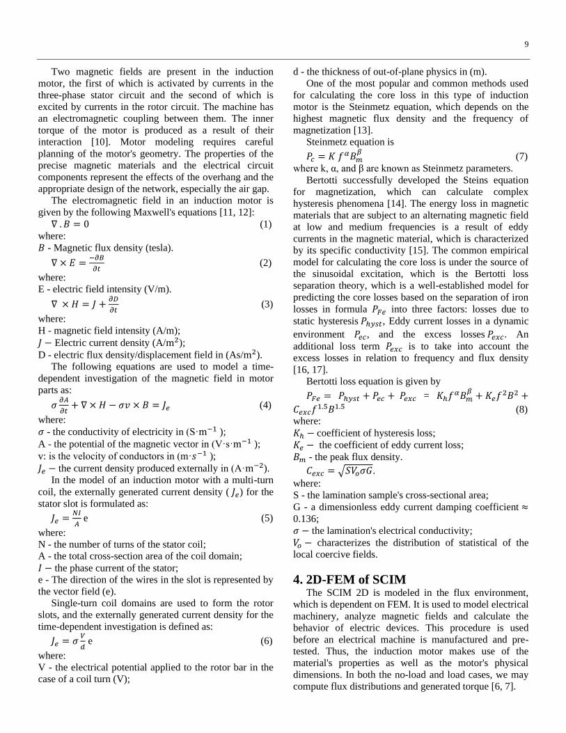
Fig. 2a shows the induction machine model that
resulted. The field lines and flux density levels for the
high power working zone are also depicted. As indicated
in Fig. 2b, the FE model is used with the machine
equivalent electrical diagram. The (FE) also represents
the stator windings and the squirrel cage by using coil
conductors (2) or a squirrel cage component (4) as field-
circuit coupling elements. This electrical diagram allows
you to define all of the external electrical elements that
need to be taken into account, such as power sources and
stator winding end turn impedances.
(a)
11
(b)
Fig. 2 a) At higher power operating point, studied machine 2D FE
model with flux density levels and field lines (the flux density range is
limited to 2.9T, and the saturated portions are shown in yellow), b) 2D
FE model of the analyzed machine's electrical diagram with (1)
sources of voltage, (2) Components for field-circuit coupling, (3)
stator end winding inductance and (4) squirrel cage
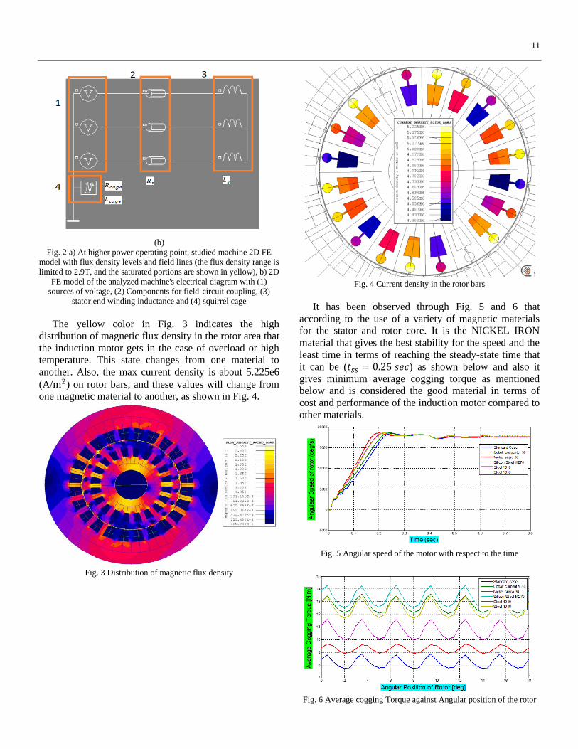
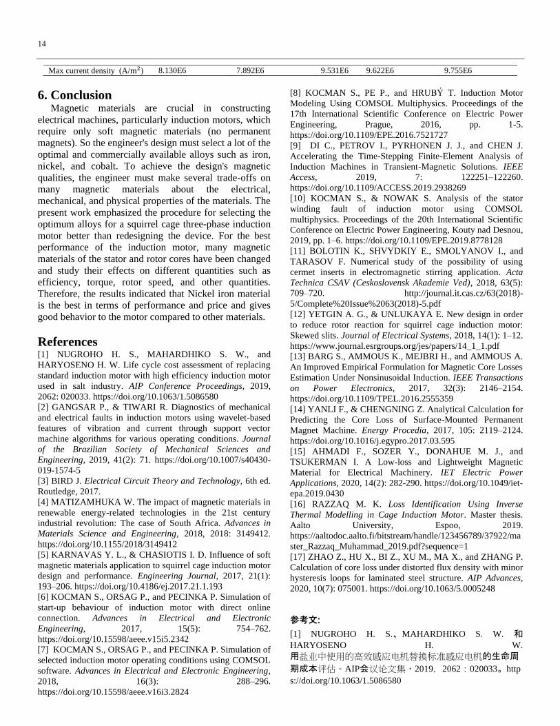
The yellow color in Fig. 3 indicates the high
distribution of magnetic flux density in the rotor area that
the induction motor gets in the case of overload or high
temperature. This state changes from one material to
another. Also, the max current density is about 5.225e6
(A/m2) on rotor bars, and these values will change from
one magnetic material to another, as shown in Fig. 4.
Fig. 3 Distribution of magnetic flux density
Fig. 4 Current density in the rotor bars
It has been observed through Fig. 5 and 6 that
according to the use of a variety of magnetic materials
for the stator and rotor core. It is the NICKEL IRON
material that gives the best stability for the speed and the
least time in terms of reaching the steady-state time that
it can be (𝑡𝑠𝑠 = 0.25 𝑠𝑒𝑐) as shown below and also it
gives minimum average cogging torque as mentioned
below and is considered the good material in terms of
cost and performance of the induction motor compared to
other materials.
Fig. 5 Angular speed of the motor with respect to the time
Fig. 6 Average cogging Torque against Angular position of the rotor

12
As can be seen from the results of the waveforms, the
motor starts with a load equal to the nominal torque. The
start of operation is associated with high currents of up to
(90 A) as shown in Fig. 7 and also high oscillations in the
internal torque of the motor that corresponds to the motor
speed as shown in Fig. 9. In 0.3 sec, the machine reaches
a stable state with speed equal to (2904 rpm). Fig. 10
shows the geometry of the induction motor through the
magnetic flux density and isolines of the magnetic vector
potential.
Fig. 7 Waveform of staring stator current
Fig. 8 Waveform of stator current with respect to time
Fig. 9 Electromagnetic torque with respect to time
(a)
(b)
Fig. 10 a) The isolines of the magnetic vector potential (An) in
(wb/𝑚2), b) the isovalues of the magnetic flux density in (T)
The goal is to analyze the transient behavior of the
motor for rated speed considering the magnetic field
harmonics caused by stator slotting, rotor, and the rotor
motion, based on transient magnetic simulations with a
rated rotor speed constant. We calculate the motor torque
values taking into account magnetic field harmonics
caused by armature slotting and rotor rotation. Different
materials were used for each simulation. The different
losses in stator and rotor, the output power, torque, and
efficiency are computed, and the results are compared to
standard case material.
Time (sec)
Time (sec)

13
Time (sec)
Fig. 11 Waveform of torque, bar current, and stator current in
transient behavior case of the motor
Table 2 Standard case STEEL _NLIN material of stator part and rotor
Values Case (N.L)
S = 0.001
Case (F.L)
S = 0.001
Stator Current (I_rms ) = (I_STA) (A) 3.33 8.35
Stator Losses (PJS) (W) 51.37 322.6
Rotor Losses (PJR) (W) 0.26 247.06
Iron Losses (2*bertotti) (W) 27.66 27.79
Power transmitted to the rotor (PTR) =
(𝑃𝑔) (W) 260.926 7720.65
Shaft Power (output mechanical
power) = (PU) (W) 260.665 7473.597
Absorbed Power (PA) (W) 312.3 8043.339
Electrical Input Power (w) ___ 8041.4
Torque (N.m) 0.82 23.78
Efficiency % 76.67 % 92.59 %
Steady State time of Speed (𝑡𝑠𝑠) (sec) ____ 0.314
Magnetic flux density [𝐵𝑚𝑎𝑥] [T] 2.181 2.561
Max current density (A/m2) 163.482E3 5.225e6
Cogging Average Torque [𝑇𝑔][N.m] 8.28608 _______
Table 3 Core materials of performance of induction motor at no load (N.L)
Test Case Case (N.L)
S=0.001
Core Materials Cobalt Iron
(carpenter 50 DC)
Steel_ 1010
_XC10) Steel 1018
Silicon Steel
M270
Nickel Iron
(Supra 36)
Stator Current (I_rms ) =
(I_STA) (A) 2.25 6.14 6.16 4.03 14.04
Stator Losses (PJS) (W) 23.51 174.41 175.56 75.33 911.47
Rotor Losses (PJR) (W) 0.41 0.34 0.4 0.43 0.29
Iron Losses (2 * Bertotti) (W) 94.53 92.64 92.4 95.86 88.52
Power transmitted to the rotor
(PTR)= (𝑃𝑔) (W) 411.939 341.86 400.56 429.07 295.2
Shaft Power (output mechanical
power= (PU) (W) 411.527 341.52 400.15 428.64 294.91
Absorbed Power (PA) (W) 435.4525 516.28 576.12 504.4 1206.68
Torque (N.m) 1.3 1.08 1.27 1.36 0.938
Efficiency % 77.64 56.06 59.8 71.4 22.76
Cogging Average Torque
[𝑇𝑔][N.m]
12.84595
10.800325
12.5498
12.60075
9.276295
Magnetic flux density [𝐵𝑚𝑎𝑥]
[T] 2.211 2.003 2.069 2.121 2.017
Max current density (A/m2) 246.153E3 245.636E3 292.665E3 290.341E3 308.008E3
Table 4 Core materials of behavior of machine at full load (F.L)
Test Case Case (F.L)
S = 0.032
Core Materials Cobalt Iron
(carpenter 50 DC) Steel_ 1010 _XC10) Steel 1018 Silicon Steel M270
Nickel Iron (Supra
36)
Stator Current (I_rms ) =
(I_STA) (A) 11.54 12.09 13.57 13 16.35
Stator Losses (PJS) (W) 615.8 676.06 851.6 786.35 1235.97
Rotor Losses (PJR) (W) 355.96 322.11 362.26 377.65 285.82
Iron Losses (2*bertotti) (W) 89.96 86.96 85.82 89.63 84.78
Power transmitted to the rotor
(PTR) = (𝑃𝑔) (W) 11123.76 10065.94 11320.67 11801.72 8928.3
Shaft Power (output
mechanical power= (PU) (W) 10767.8 9743.83 10958.41 11424.07 9342.59
Absorbed Power (PA) (W) 11739.59 10742 12172.28 12588.07 10168.16
Electrical Input Power (w) 11734.4121 10735.95 12166.2 12591.163 10164.27
Torque (N.m) 34.27 31.01 34.88 36.35 37.52
Efficiency % 90.02 89.9 89.41 90.1 91.1
Steady State time of Speed
(𝑡𝑠𝑠) (sec) 0.35 0.318 0.32 0.311 0.25
Bar Current [A] 487.505 254.918 528.792 407.972 468.463
Magnetic flux density [𝐵𝑚𝑎𝑥]
[T] 2.583 2.280 2.409 2.905 2.244
14
Max current density (A/m2) 8.130E6 7.892E6 9.531E6 9.622E6 9.755E6
6. Conclusion Magnetic materials are crucial in constructing
electrical machines, particularly induction motors, which
require only soft magnetic materials (no permanent
magnets). So the engineer's design must select a lot of the
optimal and commercially available alloys such as iron,
nickel, and cobalt. To achieve the design's magnetic
qualities, the engineer must make several trade-offs on
many magnetic materials about the electrical,
mechanical, and physical properties of the materials. The
present work emphasized the procedure for selecting the
optimum alloys for a squirrel cage three-phase induction
motor better than redesigning the device. For the best
performance of the induction motor, many magnetic
materials of the stator and rotor cores have been changed
and study their effects on different quantities such as
efficiency, torque, rotor speed, and other quantities.
Therefore, the results indicated that Nickel iron material
is the best in terms of performance and price and gives
good behavior to the motor compared to other materials.
References [1] NUGROHO H. S., MAHARDHIKO S. W., and
HARYOSENO H. W. Life cycle cost assessment of replacing
standard induction motor with high efficiency induction motor
used in salt industry. AIP Conference Proceedings, 2019,
2062: 020033. https://doi.org/10.1063/1.5086580
[2] GANGSAR P., & TIWARI R. Diagnostics of mechanical
and electrical faults in induction motors using wavelet-based
features of vibration and current through support vector
machine algorithms for various operating conditions. Journal
of the Brazilian Society of Mechanical Sciences and
Engineering, 2019, 41(2): 71. https://doi.org/10.1007/s40430-
019-1574-5
[3] BIRD J. Electrical Circuit Theory and Technology, 6th ed.
Routledge, 2017.
[4] MATIZAMHUKA W. The impact of magnetic materials in
renewable energy-related technologies in the 21st century
industrial revolution: The case of South Africa. Advances in
Materials Science and Engineering, 2018, 2018: 3149412.
https://doi.org/10.1155/2018/3149412
[5] KARNAVAS Y. L., & CHASIOTIS I. D. Influence of soft
magnetic materials application to squirrel cage induction motor
design and performance. Engineering Journal, 2017, 21(1):
193–206. https://doi.org/10.4186/ej.2017.21.1.193
[6] KOCMAN S., ORSAG P., and PECINKA P. Simulation of
start-up behaviour of induction motor with direct online
connection. Advances in Electrical and Electronic
Engineering, 2017, 15(5): 754–762.
https://doi.org/10.15598/aeee.v15i5.2342
[7] KOCMAN S., ORSAG P., and PECINKA P. Simulation of
selected induction motor operating conditions using COMSOL
software. Advances in Electrical and Electronic Engineering,
2018, 16(3): 288–296.
https://doi.org/10.15598/aeee.v16i3.2824
[8] KOCMAN S., PE P., and HRUBÝ T. Induction Motor
Modeling Using COMSOL Multiphysics. Proceedings of the
17th International Scientific Conference on Electric Power
Engineering, Prague, 2016, pp. 1-5.
https://doi.org/10.1109/EPE.2016.7521727
[9] DI C., PETROV I., PYRHONEN J. J., and CHEN J.
Accelerating the Time-Stepping Finite-Element Analysis of
Induction Machines in Transient-Magnetic Solutions. IEEE
Access, 2019, 7: 122251–122260.
https://doi.org/10.1109/ACCESS.2019.2938269
[10] KOCMAN S., & NOWAK S. Analysis of the stator
winding fault of induction motor using COMSOL
multiphysics. Proceedings of the 20th International Scientific
Conference on Electric Power Engineering, Kouty nad Desnou,
2019, pp. 1–6. https://doi.org/10.1109/EPE.2019.8778128
[11] BOLOTIN K., SHVYDKIY E., SMOLYANOV I., and
TARASOV F. Numerical study of the possibility of using
cermet inserts in electromagnetic stirring application. Acta
Technica CSAV (Ceskoslovensk Akademie Ved), 2018, 63(5):
709–720. http://journal.it.cas.cz/63(2018)-
5/Complete%20Issue%2063(2018)-5.pdf
[12] YETGIN A. G., & UNLUKAYA E. New design in order
to reduce rotor reaction for squirrel cage induction motor:
Skewed slits. Journal of Electrical Systems, 2018, 14(1): 1–12. https://www.journal.esrgroups.org/jes/papers/14_1_1.pdf
[13] BARG S., AMMOUS K., MEJBRI H., and AMMOUS A.
An Improved Empirical Formulation for Magnetic Core Losses
Estimation Under Nonsinusoidal Induction. IEEE Transactions
on Power Electronics, 2017, 32(3): 2146–2154.
https://doi.org/10.1109/TPEL.2016.2555359
[14] YANLI F., & CHENGNING Z. Analytical Calculation for
Predicting the Core Loss of Surface-Mounted Permanent
Magnet Machine. Energy Procedia, 2017, 105: 2119–2124.
https://doi.org/10.1016/j.egypro.2017.03.595
[15] AHMADI F., SOZER Y., DONAHUE M. J., and
TSUKERMAN I. A Low-loss and Lightweight Magnetic
Material for Electrical Machinery. IET Electric Power
Applications, 2020, 14(2): 282-290. https://doi.org/10.1049/iet-
epa.2019.0430
[16] RAZZAQ M. K. Loss Identification Using Inverse
Thermal Modelling in Cage Induction Motor. Master thesis.
Aalto University, Espoo, 2019.
https://aaltodoc.aalto.fi/bitstream/handle/123456789/37922/ma
ster_Razzaq_Muhammad_2019.pdf?sequence=1
[17] ZHAO Z., HU X., BI Z., XU M., MA X., and ZHANG P.
Calculation of core loss under distorted flux density with minor
hysteresis loops for laminated steel structure. AIP Advances,
2020, 10(7): 075001. https://doi.org/10.1063/5.0005248
参考文:
[1] NUGROHO H. S.、MAHARDHIKO S. W. 和
HARYOSENO H. W.
用盐业中使用的高效感应电机替换标准感应电机的生命周
期成本评估。AIP会议论文集,2019,2062:020033。http
s://doi.org/10.1063/1.5086580

15
[2] GANGSAR P., & TIWARI R.
使用基于小波的振动和电流特征通过支持向量机算法在各
种操作条件下诊断感应电机中的机械和电气故障。巴西机
械科学与工程学会杂志,2019,41(2): 71.
https://doi.org/10.1007/s40430-019-1574-5
[3] BIRD J. 电路理论与技术,第 6 版。劳特利奇,2017。
[4] MATIZAMHUKA W.
磁性材料对21世纪工业革命中可再生能源相关技术的影响
:以南非为例。材料科学与工程进展, 2018, 2018: 3149412.
https://doi.org/10.1155/2018/3149412
[5] KARNAVAS Y. L., & CHASIOTIS I. D.
软磁材料应用对鼠笼式感应电机设计和性能的影响。工程
杂志, 2017, 21(1): 193–206。
https://doi.org/10.4186/ej.2017.21.1.193
[6] KOCMAN S.、ORSAG P. 和 PECINKA P.
直接在线连接感应电机启动行为的仿真。电气与电子工程
进展, 2017, 15(5): 754–762。
https://doi.org/10.15598/aeee.v15i5.2342
[7] KOCMAN S.、ORSAG P. 和 PECINKA P. 使用
COMSOL软件模拟选定的感应电机运行条件。电气与电子
工程进展, 2018, 16(3): 288–296。
https://doi.org/10.15598/aeee.v16i3.2824
[8] KOCMAN S.、PE P. 和 HRUBÝ T. 使用
COMSOL多物理场进行感应电机建模。第17届国际电力工
程科学会议论文集,布拉格,2016,第 1-5 页。
https://doi.org/10.1109/EPE.2016.7521727
[9] DI C.、PETROV I.、PYRHONEN J. J. 和 CHEN J.
加速瞬态磁解决方案中感应电机的时间步进有限元分析。I
EEE访问,2019,7:122251–
122260。https://doi.org/10.1109/ACCESS.2019.2938269
[10] KOCMAN S., & NOWAK S. 使用
COMSOL多物理场分析感应电机定子绕组故障。第20届国
际电力工程科学会议论文集,考蒂纳德德斯努,2019,第
1-6 页。 https://doi.org/10.1109/EPE.2019.8778128
[11] BOLOTIN K.、SHVYDKIY E.、SMOLYANOV I. 和
TARASOV F.
在电磁搅拌应用中使用金属陶瓷插件的可能性的数值研究
。技术学报(捷克斯洛伐克科学院), 2018, 63(5): 709–
720。http://journal.it.cas.cz/63(2018)-
5/Complete%20Issue%2063(2018)-5.pdf
[12] YETGIN A. G., & UNLUKAYA E.
为减少鼠笼式感应电机转子反作用而设计的新设计:斜缝
。电气系统杂志, 2018, 14(1): 1-12。
https://www.journal.esrgroups.org/jes/papers/14_1_1.pdf
[13] BARG S.、AMMOUS K.、MEJBRI H. 和 AMMOUS
A. 非正弦感应下磁芯损耗估计的改进经验公式。IEEE
电力电子学报,2017,32(3):2146–
2154。https://doi.org/10.1109/TPEL.2016.2555359
[14] YANLI F., & CHENGNING Z.
预测表面贴装永磁电机磁芯损耗的分析计算。能源学报,
2017,105:2119-
2124。https://doi.org/10.1016/j.egypro.2017.03.595
[15] AHMADI F.、SOZER Y.、DONAHUE M. J. 和
TSUKERMAN I.
一种用于电机的低损耗轻质磁性材料。国际教育与培训中
心电力应用,2020,14(2):282-
290。https://doi.org/10.1049/iet-epa.2019.0430
[16] RAZZAQ M. K.
在笼式感应电机中使用逆热模型进行损耗识别。硕士论文
。阿尔托大学,埃斯波,2019。https://aaltodoc.aalto.fi/bitst
ream/handle/123456789/37922/master_Razzaq_Muhammad_2
019.pdf?sequence=1
[17] ZHAO Z., HU X., BI Z., XU M., MA X., 和 ZHANG P.
计算具有较小磁滞回线的叠层钢结构畸变磁通密度下的磁
芯损耗。AIP 预付款, 2020, 10(7): 075001.
https://doi.org/10.1063/5.0005248