Performance analysis of Givens rotation integrated optical interdigitated-electrode cross-channel...
8
Performance analysis of Givens rotation integrated optical interdigitated-electrode cross-channel Bragg diffraction devices: intrinsic accuracy Erik 1. Verriest, Elias N. Glytsis, and Thomas K. Gaylord The intrinsic accuracy due to the physical limitations of the Bragg diffraction is analyzed for the integrated optical Givens rotation device. This device is a basic building block for analog vector and matrix operations. The equivalent fixed point and floating point digital accuracies of the device are analyzed. Under various measures of proximity, it is shown that the accuracies can be as high as 10 bits. 1. Introduction A. Optics vs Electronics Optical computation is an exciting new field offering great potential for large-scale, high-speed computing. However, the nature of this potential must be well understood before it can be successfully utilized. As the attributes of optics differ dramatically from those of electronics, a one-for-one substitution of optical devices for electronic devices should not be attempted. Together with the emerging special purpose VLSI ar- ray processors which have become an appealing alter- native in real time signal processing systems,' they share the critical attributes of regularity, recursivity, and local communication with most signal processing algorithms. In contrast to the VLSI processors, the optical implementations are generally faster, at the expense of decreased accuracy. It is expected that analog optical processing systems, efficiently taking advantage of the inherent attributes of optics, may provide the edge needed for real time solutions to some large-scale complex processing problems. The appli- cation domain of such processors covers a broad range, including digital filtering, spectral estimation, adap- tive array processing, image processing with pattern recognition and classification, seismic and tomograph- ic signal processing. 2 The authors are with Georgia Institute of Technology, School of Electrical Engineering, Atlanta, Georgia 30332-0250. Received 12 December 1989. 0003-6935/90/172556-08$02.00/0. © 1990Optical Society of America. B. Optical Givens Rotation Device In Refs. 3 and 4, a coherent optical device was intro- duced, capable of encoding a rotation of a 2-D vector over an arbitrarily preset angle. It was shown that the implementation, using waveguides and tunable dif- fraction gratings, on an integrated optical chip is feasi- ble. As many fundamental problems and algorithms of numerical linear algebra involve combinations of elementary rotations, 5 either in parallel or serial, the possibility of designing large integrated optical circuits for analog solutions to specific computations in nu- merical algorithms becomes possible. Such analog solutions are superior in a different realm compared to their digital counterparts, due to the different favor- able attributes of optics vs electronics. In the time domain, there is the potential for high speed; while in the spatial domain, the possibility of massive parallel- ism and potentially high interconnectivity is manifest. In brief: 1. Large bandwidth. The high carrier frequency (_1014 Hz) offers the potential for very large band- width, and consequently high speed operation. This is the attribute that has been primarily responsible for the success of fiber optics, for example. 2. Parallelism. Integrated optical (2-D) and bulk optical (3-D) systems are capable of handling and pro- cessing many channels of data simultaneously. This is, for instance, successfully exploited in side-looking radar data processing. 3. Interconnectivity. In optical form, channels of data may physically pass through each other without altering the data. This, of course, is in contrast to charge-based signals in metallic conductors that must remain separated from each other. Interconnectivity allows the switching (interchanging or broadcasting) of data channels in any arbitrary pattern. 2556 APPLIEDOPTICS / Vol. 29, No. 17 / 10 June 1990
Transcript of Performance analysis of Givens rotation integrated optical interdigitated-electrode cross-channel...

Performance analysis of Givens rotation integrated opticalinterdigitated-electrode cross-channel Braggdiffraction devices: intrinsic accuracy
Erik 1. Verriest, Elias N. Glytsis, and Thomas K. Gaylord
The intrinsic accuracy due to the physical limitations of the Bragg diffraction is analyzed for the integratedoptical Givens rotation device. This device is a basic building block for analog vector and matrix operations.The equivalent fixed point and floating point digital accuracies of the device are analyzed. Under variousmeasures of proximity, it is shown that the accuracies can be as high as 10 bits.
1. Introduction
A. Optics vs Electronics
Optical computation is an exciting new field offeringgreat potential for large-scale, high-speed computing.However, the nature of this potential must be wellunderstood before it can be successfully utilized. Asthe attributes of optics differ dramatically from thoseof electronics, a one-for-one substitution of opticaldevices for electronic devices should not be attempted.Together with the emerging special purpose VLSI ar-ray processors which have become an appealing alter-native in real time signal processing systems,' theyshare the critical attributes of regularity, recursivity,and local communication with most signal processingalgorithms. In contrast to the VLSI processors, theoptical implementations are generally faster, at theexpense of decreased accuracy. It is expected thatanalog optical processing systems, efficiently takingadvantage of the inherent attributes of optics, mayprovide the edge needed for real time solutions to somelarge-scale complex processing problems. The appli-cation domain of such processors covers a broad range,including digital filtering, spectral estimation, adap-tive array processing, image processing with patternrecognition and classification, seismic and tomograph-ic signal processing. 2
The authors are with Georgia Institute of Technology, School ofElectrical Engineering, Atlanta, Georgia 30332-0250.
Received 12 December 1989.0003-6935/90/172556-08$02.00/0.© 1990 Optical Society of America.
B. Optical Givens Rotation Device
In Refs. 3 and 4, a coherent optical device was intro-duced, capable of encoding a rotation of a 2-D vectorover an arbitrarily preset angle. It was shown that theimplementation, using waveguides and tunable dif-fraction gratings, on an integrated optical chip is feasi-ble. As many fundamental problems and algorithmsof numerical linear algebra involve combinations ofelementary rotations,5 either in parallel or serial, thepossibility of designing large integrated optical circuitsfor analog solutions to specific computations in nu-merical algorithms becomes possible. Such analogsolutions are superior in a different realm compared totheir digital counterparts, due to the different favor-able attributes of optics vs electronics. In the timedomain, there is the potential for high speed; while inthe spatial domain, the possibility of massive parallel-ism and potentially high interconnectivity is manifest.In brief:
1. Large bandwidth. The high carrier frequency(_1014 Hz) offers the potential for very large band-width, and consequently high speed operation. This isthe attribute that has been primarily responsible forthe success of fiber optics, for example.
2. Parallelism. Integrated optical (2-D) and bulkoptical (3-D) systems are capable of handling and pro-cessing many channels of data simultaneously. Thisis, for instance, successfully exploited in side-lookingradar data processing.
3. Interconnectivity. In optical form, channels ofdata may physically pass through each other withoutaltering the data. This, of course, is in contrast tocharge-based signals in metallic conductors that mustremain separated from each other. Interconnectivityallows the switching (interchanging or broadcasting)of data channels in any arbitrary pattern.
2556 APPLIED OPTICS / Vol. 29, No. 17 / 10 June 1990

C. Accuracy Analysis
In practice, a variety of deviations from the idealdevice behavior are possible during operation and areal implementation of the device differs from theideal. An analysis of the accuracy of the device is,therefore, essential before the accuracy of the analogalgorithms implemented can be evaluated. In Ref. 3,the triangularization of a matrix was treated. A com-panion paper6 treats several numerical algorithm im-plementations in detail. Three classes of potentialproblems can be categorized.
A first major category consists of the intrinsic errors.These can further be subdivided into two classes:technological errors, induced by the inaccuracies in theconstruction of the device, and principal errors, in-duced by nonideal behavior, inherent in the physics ofthe device itself. In this paper, technological errorswill be neglected, since the device technology hasstretched beyond the limits where the other inaccura-cies become important. The principal or physical er-rors stem from the real device constraints, much likethe Heisenberg uncertainty principle represents a fun-damental limitation on the physical behavior that isindependent of the technology. This analysis will de-termine what to expect in optimal conditions.
The second major category are the extrinsic errors,occurring externally at the input or preparation stagesand at the detection or observation stages. A thirdmajor category of errors constitute the inherent errors.These appear not as a source, but as the evolution andpropagation (possibly with amplification) in the nu-merical algorithms. This paper treats the intrinsicerrors. Extrinsic and inherent errors will be discussedin a companion paper,6 where calibration is also treat-ed.
This paper is organized into six sections. In Sec. II,the operation of the integrated optical Givens rotationdevice, in the harmonic regime, is briefly described.Its intrinsic accuracy due to the physical limitations ofthe Bragg-diffraction is discussed in Sec. III, where itwill be assumed (in a classical treatment) that theaccuracy of observation and preparation can be ob-tained with arbitrarily high precision, at the expense ofthe operation speed. Such a classical treatment is, ofcourse, invalid in the quantum limit, but this will notbe discussed here as it is beyond the expected mode ofoperation of the device. Section IV, then, continueswith the additional intrinsic errors due to bends, cros-stalk, etc. In Sec. V, an equivalent digital accuracy isdefined and computed for the device. Conclusions aresummarized in Sec. VI.
11. Integrated Optical Givens Rotation Device
As described in Ref. 4, the ideal transfer matrixbetween an input vector x and an output vector y in theGivens rotation operation may be represented usingthe plane rotation matrix. That is,
[Yi] = [cos -sin[] .(1)
wh2 sin C 2b
where is the rotation angle. This may be written
X1 Y2 x1sino + X2cos tL t 1 -
x2 Y1= x1cos 0- 2 sin
Fig. 1. Schematic of the optical Givens rotation device. The x-components are the input beams; the y-components the output
beams.
compactly as y = Rx, where the output vector y =[Y1 ,Y 2]T, R is the rotation matrix, the input vector =[xbx2] T, and where T denotes transpose. An equiva-lent scalar representation, is developed in Ref. 7, wherethe notion of a quasor is introduced. In this notation,the 2-D harmonic signals, in phasor notation [Alexp(j0i), A2 exp(j02)]T are encoded by the scalar A1exp(j401) + iA2 exp(j02), in the quaternion field Q.The quaternion algebra, which is four dimensionalwith basis (1,ij,k), is a doubling of the complex num-ber algebra. When all signals are correctly in phase,this representation has the advantage of yielding pow-erful graphical techniques in the (1,i) subfield of Q.termed the Q-plane in Ref. 7.
Equation (1) is readily mapped to a lossless trans-mission line structure, exploiting the wave propaga-tion effects in a natural way. The device reported inRef. 4 uses electrooptic grating diffraction and phaseshifting to achieve the required sine and cosine weight-ed combinations of the input beams. The sine andcosine weights are a natural result of the diffraction bya thick transmission phase grating,8 induced by a volt-age applied to interdigitated periodic metallic elec-trodes over the intersection of the waveguides in theelectrooptic material.
The summations in the Givens rotation are achievedby superposition i.e., the coherent combination of theoutput waves from the grating. At usual operatingpower levels, the nonlinear effects of the medium arenegligible. The phases of the waves are adjusted withelectrooptic phase shifters to achieve the required ad-dition and subtraction indicated in Eq. (1). The cor-rect phase relationships between the input waves andthe output waves are obtained by introducing fixedphase shifters r1 and r 2 into the device. These phaseshifts are produced by applying constant voltages toelectrodes over one of the waveguides.
The complete optical Givens rotation device com-bines these operations into a single device as schemati-cally illustrated in Fig. 1. A top view of the integratedoptical implementation of this device is shown in Fig.2. The rotation angle t' of the device may be expressedas V = KV, where K is the gain (in radians/volt) and Vis the voltage applied to the grating electrodes. In Ref.4, an analytic formula is presented for the gain K interms of the device and constitutive parameters. Theinversion of the order of the components of the outputvector can be remedied by cascading two rotators, withnet rotation angle equal to the desired rotation angle.
10 June 1990 / Vol. 29, No. 17 / APPLIED OPTICS 2557

y 1
Fig. 2. A top view of the physicalconfiguration of the integrated
optical Givens rotation device.
III. Intrinsic Accuracy of the Bragg Diffraction
A. Bragg Diffraction Limitations
As defined earlier, the intrinsic errors are the devi-ations from the nominal or theoretical operation due tothe physical limitations. Detailed analysis of the de-vice physics reveals several possible deviations fromthe desired rotation transformation given by Eq. (1).First, the Bragg diffraction phenomenon yields higher-order diffracted beams, which were neglected in Ref. 4.As power is conserved, the zero-order transmitted andfirst-order diffracted beam power do not sum to theinput beam power.
A rigorous diffraction analysis9 "10 yields the ampli-tudes of the zero-order transmitted and the first-orderdiffracted beams. These amplitudes as functions ofthe applied grating voltage V are B(V) and B(V),respectively. The graphs of the normalized diffrac-tion amplitudes B,(V) and B,(V) are shown in Fig. 3.The plot of B,(V) vs B(V), with V as parameter isnearly circular. Using a least-squares fit of [sin(KV),cos(KV)] to [B(V),B,(V)], the gain K was determinedto be K = 0.1231 rad/v. The match with the exactcosine and sine curve is shown in Figs. 4 and 5, wherecos-'[B,(V)] - KV and sin-'[B(V)] - KV are dis-played. Various other graphs are deduced from this,e.g., Fig. 6 shows the grating strength gain K(V) =cos-'(B(V))/V and K,(V) = sin-'(B,(V))/V as func-tions of the applied voltage. They represent a local oreffective value of this gain, since the grating strength is4,(V) = K(V) V. Ideally K(V) and K 8(V) should beconstant. The least-squares-fitted constant gain(global gain) is also indicated. The loss of signal powerdue to the higher-order diffracted beams is apparent inthe attenuation curve of Fig. 7, which shows the sum ofthe zero-order transmitted and first-order diffractedpower. Here the sum of the first-order diffracted and
0
U- a3,
W .
NE2
oiEC0Z
0 30 40VOLTAGE, V (volts)
60
Fig. 3. Normalized zero-order transmitted amplitude B,(V) andfirst-order diffracted amplitude B,(V).
> 0.5
- 0
In0 -0.5
-1.00 10 20 30 40 50
VOLTAGE, V (volts)
Fig. 4. Deviation from linearity of the cosine argument:KV = cos-1[B,(V)] - KV.
60
KC(V)V-
zero-order transmitted powers is shown as a functionof the voltage applied to the grating. The attenuationincreases with the absolute value of the applied volt-age.
An empirical formula may be fitted to these data.
2558 APPLIED OPTICS / Vol. 29, No. 17 / 10 June 1990
xi
X2

of cos(kV). In this sense, a unit input amplitude willbe diffracted with an amplitude of
Bs(V) = sin(KV) cos(kV) = /2 sin[(K + k)V] + '/2 sin[(K-k)lV,(4)
and a transmitted amplitude of
B,(V) = cos(KV) cos(kV) = l/2 cos[(K + k)V] + /2 cos[(K- k)V].
(5)
lo 20 30VOLTAGE, V (volta
Fig. 5. Deviation from linearity of the sinEKV = sin-1 [B,(V)] - K
:i _
3 0 12.4I ,0 mZ 'a 12.3i_ N
U !O
CJ X5 12.2-<X -
LI 12.1-
40 50 do Therefore, the actual outputs B,( V) and B,( V) may beinterpreted as an average of the sine and cosine evalua-
e argument: K(V) V - tions at two neighboring angles of the corresponding,v. nominal angle. Empirically, k can be determined by a
least-squares fit of the data of Fig. 7. It is k 0.003rad/V, which makes k/K of order 0.024.
B. Four-Port Bragg Device
Consider now the four-port device with independentsignal inputs. Let B(V) be a matrix relating the outputbeam amplitudes to the input beam amplitudes for agrating voltage V. Using a symmetry argument, to-gether with the previously established empirical B,( V)and B,(V) functions, and invoking linear superposi-tion, the transfer matrix,
0 10 20 30 4VOLTAGE, V (volts)
40 50
Fig. 6. Grating strength gain K(V) for sine (Ks) and cosine (K,)generation. The least-squares fitted constant gain (global gain) Kisalso indicated. The gain is related to the grating strength by ,(V) =
K(V)V.
t1.00
+
095N 0.99'm11l
5-N0
60 (V) = [Bc(V) -B (V)] (6)
is readily deduced. In general, B(V) is not an exactrotation, but because of its specific structure, its singu-lar value decomposition is trivial. One finds the de-generate form B(V) = o(V)R[0(V)], with o-(V) a scalarsatisfying Eq. (2), which is displayed in Fig. 7, andwhere R[0(V)] is an exact rotation matrix with rotationangle 0(V), satisfying
tanO(V) = B 8(V)/Bj(V).
I 10 20 30 40VOLTAGE, V (volts)
Fig. 7. The sum of zero-order transmitted and first-order diffraed power.
The combined power in the zero-order transmitt(and the first-order diffracted wave, a2(V) is
(V) = B(V) + B2(V)
(7)
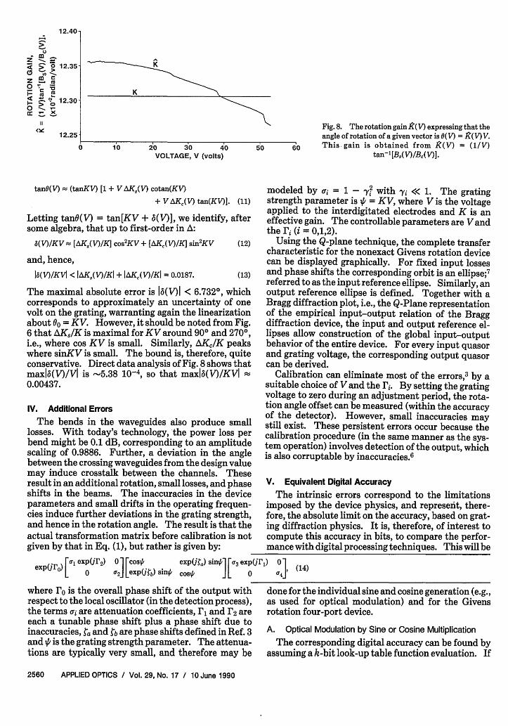
The physical device, therefore, performs a slightlyreduced rotation over an angle 0(V), where 0(V) is verynearly a linear function of V. In fact, setting 0(V) =IZ(V) V, a slight nonlinearity is revealed by the rotationgain K(V) vs V as shown in Fig. 8. Since in the neigh-borhood of 3600, c(V)2 is -0.986, a conservative bound
0 for the attenuation error is 0.007; i.e., a(V) is assumedto be uniformly distributed in (1 - e,1), with e = 0.007.
t- A uniform bound for the angular deviations, may beset starting from the effective grating strength gains(Fig. 6). Setting
Ad
(2)
Noting that a2( V) is nearly second-order in the voltage,then
92(V) _ (1 - (kV)/2)2, (3)
where k is a constant to be determined. For the volt-ages of interest (corresponding with at most 3600 rota-tion), the deviation is sufficiently small, so that v(V)can be approximated by a truncated Taylor expansion
K,(V) = sin- [B(V)]/V = K + AK 8(V)
Kc(V) = cos' [B,(V)]/V = K + AKJ(V)
it can be deduced that
sinKV[1 + AK,(V)/K]cosKV[1 + AK,(V)/K]
(8)
(9)
(10)
Since in the interval (-360°,360°) one findsmax1AK,/KI = 0.00813 and maxIAK 2/KI = 0.01057, themaximal angular deviation (corresponding to KV =3600) is 3.8°. An expansion up to first order leads to
10 June 1990 / Vol. 29, No. 17 / APPLIED OPTICS 2559
0.5 -Bd
o- 0.0-qmEc
roan I . . . . I-us:so
-
12.40-
-z m _
0 12.35;s ~! >0 0_, C X
F: ' '0 12.30a: -_ x~
11
<X 12.25
0 10 20 30VOLTAGE, V (volts
" Fig. 8. The rotation gain R(V) expressing that theangle of rotation of a given vector is (V) = R(V) V.
40 50 60 This- gain is obtained from K(V) = (1/V)s) ~~~~~~~~~~~~tan-' [B,,(Y)1B,,(V)l
tan(V) (tanKV) [1 + VAK,(V) cotan(KV)
+ V AKC(V) tan(KV)]. (11)
Letting tan(V) = tan[KV + 6(V)], we identify, aftersome algebra, that up to first-order in A:
5(V)IKV- [AK8(V)IK] cos2KV+ [AK,(V)/K] sin2KV (12)
and, hence,
1a(V)/KV1 < IAK8 (V)/KI + IAK,(V)/KI = 0.0187. (13)
The maximal absolute error is 16(V)I < 6.732°, whichcorresponds to approximately an uncertainty of onevolt on the grating, warranting again the linearizationabout 00 = KV. However, it should be noted from Fig.6 that AK,/K is maximal for KV around 900 and 270°,i.e., where cos KV is small. Similarly, AKIK peakswhere sinKV is small. The bound is, therefore, quiteconservative. Direct data analysis of Fig. 8 shows thatmaxlb(V)/Vl is -5.38 10-4, so that maxlb(V)/KVI0.00437.
IV. Additional Errors
The bends in the waveguides also produce smalllosses. With today's technology, the power loss perbend might be 0.1 dB, corresponding to an amplitudescaling of 0.9886. Further, a deviation in the anglebetween the crossing waveguides from the design valuemay induce crosstalk between the channels. Theseresult in an additional rotation, small losses, and phaseshifts in the beams. The inaccuracies in the deviceparameters and small drifts in the operating frequen-cies induce further deviations in the grating strength,and hence in the rotation angle. The result is that theactual transformation matrix before calibration is notgiven by that in Eq. (1), but rather is given by:
modeled by a = 1 - y with yi << 1. The gratingstrength parameter is ' = KV, where V is the voltageapplied to the interdigitated electrodes and K is aneffective gain. The controllable parameters are Vandthe Fi (i = 0,1,2).
Using the Q-plane technique, the complete transfercharacteristic for the nonexact Givens rotation devicecan be displayed graphically. For fixed input lossesand phase shifts the corresponding orbit is an ellipse;7referred to as the input reference ellipse. Similarly, anoutput reference ellipse is defined. Together with aBragg diffraction plot, i.e., the Q-Plane representationof the empirical input-output relation of the Braggdiffraction device, the input and output reference el-lipses allow construction of the global input-outputbehavior of the entire device. For every input quasorand grating voltage, the corresponding output quasorcan be derived.
Calibration can eliminate most of the errors,3 by asuitable choice of V and the rs. By setting the gratingvoltage to zero during an adjustment period, the rota-tion angle offset can be measured (within the accuracyof the detector). However, small inaccuracies maystill exist. These persistent errors occur because thecalibration procedure (in the same manner as the sys-tem operation) involves detection of the output, whichis also corruptable by inaccuracies. 6
V. Equivalent Digital Accuracy
The intrinsic errors correspond to the limitationsimposed by the device physics, and represent, there-fore, the absolute limit on the accuracy, based on grat-ing diffraction physics. It is, therefore, of interest tocompute this accuracy in bits, to compare the perfor-mance with digital processing techniques. This will be
exp(ro) [Al exp(jr2 ) 0 l oso exp(Uta) sin] [ra3 exp(urF) 0 (1e 0 ` 2 J[exp(b) sing cost 0 aLJ°(14)
where ro is the overall phase shift of the output with done for the individual sine and cosine generation (Erespect to the local oscillator (in the detection process), as used for optical modulation) and for the Givthe terms ai are attenuation coefficients, r and r2 are rotation four-port device.each a tunable phase shift plus a phase shift due toinaccuracies, , and gb are phase shifts defined in Ref.3 A. Optical Modulation by Sine or Cosine Multiplicationand Vt is the grating strength parameter. The attenua- The corresponding digital accuracy can be foundtions are typically very small, and therefore may be assuming a k-bit look-up table function evaluation.
ens
l by
if
2560 APPLIED OPTICS Vol. 29, No. 17 / 10 June 1990
] - | |

Table 1. Direct Operation: Circular Functions
Domain of (R + maxlf'ID) Empirical Digitaloperation Function R D D deviation accuracy
[-360°,3600] sin 2 4wr 2(1 + 2ir) 0.02 8.5cos 2 4ir 2(1 + 2ir) 0.0094 9.6
[-180°,180°] sin 2 2ir 2(1 + 7r) 0.008 9.0cos 2 27r 2(1 + 7t) 0.0063 9.3
-900, 900] sin 2 7r 2 + r 0.0022 10.2cos 1 ir 1 + r 0.0058 8.5
Note: Equivalent digital accuracy (given as wordlength in bits) for the use of the Givens rotationdevice in computing the sine and cosine functions as a function of the size of the domain (D) and range(R).
the exact function y = f(x) is continuous, the k-bitrounded approximation is rk{f[rk(x)]}, i.e., both the ar-gument and the value are rounded to k-bit accuracy,represented by the function rk. Dividing both thedomain D, and the range R of f in 2k bins, the digitalaccuracy is Ak(x) = Irkff[rk(x) - f(x)I and so
A¾(x) < Irkif[rk(x)] - f[rk(x)] I + If[rk(x)] - (x)I
• 2-(k+l)(R + I(x)ID).
S 2-(k+l)(R + maxIf'(x)ID). (15)(R D
Clearly the accuracy is a monotonic function of thelength of the domain of the function f(-). If an analogdevice which computes f(.), actually yields a perturbedversion F(-), the equivalent bit accuracy will be definedas the value of k for which the analog accuracy boundmT x -F(x) -f(x)l matches the bound mx Ak. Per-forming this evaluation for the direct sine and cosinegeneration, the results are summarized in Table I, forvarious domains.
The inverse operations can also be checked. In areverse operation mode, the device enables the evalua-tion of sin-1(x) and cos-1 (x). The digital accuracy ofthe f(-) = sin-1 (-) function is also determined by
Ak(X) = Irkf[rk(x)] - f(x)I and so
Ak(X) • (1/2 )2 kir + 7r/2 - sin 1[1 -(1/2)2k2]
S 2-(k+l) + COS'[1 - 2 -k], (16)
where R = 7r,D = 2, and 7r/2 - sin-'(x) = cos1'(x) havebeen used. This digital accuracy can then again becompared with the accuracy of the inverse of the ana-log function KB,- 1 (x)-sin'1(x). Note that the rangeof this function is expressed in radians rather thanvoltage units.
B. Digital Accuracy of the Givens Rotation
Consider first a class of matrices of the form:
M(a,3) = [a -J (17)[A a] (17
These matrices correspond to a rotation over an angle 0= tan-'/a, and a scaling by a = (a2 + f#2)1/2. Let nowFj(o) and F8(6) be functions of 0 which are in somesense close respectively to coso and sin. The approx-imate Givens rotation matrix will now be analyzed for
three different notions of closeness. The deviationbetween the nominal () and the actual () rotationangle will be denoted by 5.
1. The Distance Measures for the HarmonicFunctions
For case 1 (closeness in the absolute sense), let theabsolute deviations from coso and sin be normalized,so that in the representation below, Gj(o) and G,(q)are maximally equal to one:
Fjo) = coso + e Go),
FS(O) = sine + e Qjo)
(18)
(19)
This corresponds to e := max(jF,(0) - coskI, IF,(,O) -sinkl), and can then be interpreted as a homotopyparameter. It follows then that a2(e,0), given by FC(,%)+ F2(k) yields
a2(,) = 1 + 2e(GjGk) sine + Gj(q) cost) + e2(G,(0) 2 + G,(40)2),
(20)
from which(21)joa(e,0)-11 -5 e(G,(/0)2 + Gj(o)2)1/2.
This in turn implies that
a(e,0) a(e) E [1 -0e,1 + Ed],
since G(4) = max [G,(p)2 + GC(p)2]1 /2 < J_. Similarly,one can find after some algebra that
(23)|6(e,01 S sin'Ie[G,(4,) 2 + G,(p) 2]1"2 1,
and, thus,
j6(E,tk)I S I6(E)I = sin'l(e).
(22)
(24)
For case 2 (closeness in a relative sense), the devi-ations from the nominal behavior are now modeled as
FJO = [1 + eHc(W] cosO,
Fs(q5) = [1 + eHjGk)] sinb,
(25)
(26)
where, as before, H(q) and Hh(o) have been normal-ized (to the interval [-1,1], and the homotopy parame-ter e := max (IFA) - coskl, IF,(O) - sinkl) has beenintroduced. One finds now that
(27)- 11 S e max(IHf(O)I, H(O)I),
from which the uniform bound
10 June 1990 / Vol. 29, No. 17 / APPLIED OPTICS 2561

Table 11. Direct Operation: Givens Rotation
Domain of a2 la(e) - 11operation krx kfloat
[-360°,360°] [0.987,1] 0.0065 7.26 7.76[-180o,180oI [0.998,1] 0.001 9.97 10.47[ 90O, 900] [0.999, 1] 0.0005 10.97 11.47
Note: Equivalent fixed-point (kr,8) and floating-point (kfoat) dig-ital accuracy (in bits) of the Givens rotation device, based on close-ness in the relative sense, as computed from a.
la(e,) - 11 S (e) - 11 = e, (28)
follows. The angular deviation is obtained as
16(e,,0)j = sin( 12[H(k) -H,()]l
{1 + 1I2e[Hs(k) + H,(0)]j) S 6(e) = sin-'e (29)
For case 3 (closeness in the argument), this can beviewed as closeness of the inverse function. Here theinaccurate model is
FC(O) = cos[t + ec(o)], (30)
F,(q) = sin[0 + eAs(o)], (31)
then one finds that
cose - sine S a(e) • cose + sine, (32)
1|(e) e + sine/(1 - 2 sin2 e)"2 . (33)
The right-hand side of the latter is, to first-order in e,equal to 2e.
2. Fixed and Floating Point AccuraciesThe above derived bounds can now be applied to the
accuracy of the Givens rotation using a fixed wordlength look-up table. This shall be done for both fixedpoint and floating point representations. Firstbounds for the digital representation error are ob-tained, and then compared to the empirical Givensrotation error.
To analyze the fixed point error of the Givens rota-tion, let FW(f) = rk(cosO), and F(o) = rk(sino), whererk( ) is a rounding function for k bits, we have
Ix - rk(x)I (1/2)2-k = 2 (k+) := Pk = e. (34)
Applying the case 1 analysis with e = Pk and settinga(pk) = a(k), (35)
a(pk) = 6f,(k), (36)
one gets
lofi(k) -11 < 2 -(k+12)
lbfix(k)l sin-'(2 -(k+1/2)). (38)
To analyze the floating point error of the Givensrotation, it is taken that k bits are allocated to thefraction (in standard floating point representation),and that underflow and overflow do not occur. Then
lx - rk(x)I • 2 kx := PkX. (39)
Now we have Fj() = [1 + Pki2c()] cosq, and F(O) = [1+ PkQs,(0)I sine, with IQ 0Gk)I and $IQ0J)I 1. Theresults of the case 2 analysis give, with
a(pk) = afp(k), (40)
6(Pk) = 6flop(k), (41)
the bounds
lafol(k) -11 p = 2 ,
16flop(k)l sin-'(2 -h).
(42)
(43)
How do these results now compare to the accuracy ofthe optical Givens rotation device? The results inTable II are derived from the empirical results dis-played in Figs. 7 and 8. The angular deviation led to apoorer result.
Alternatively, from the case 3 analysis, using respec-tively the empirical functions Bc and B, for F, and F,the deviations can be derived. The results are summa-rized in Table III. The reason that these results aremore conservative is that only the bounds for Bc and B,are used, and the cooperative effect of these functionsin the generation of the rotation has not been utilized.
VI. Conclusions
The intrinsic errors for the direct evaluation of thesine and cosine functions and the Givens rotation de-vice were analyzed. This represents the ultimatephysical limits to the device, based on Bragg diffrac-tion physics. It was found that an equivalent digitalaccuracy, (defined by look-up table matching) of -10bits may be obtainable. In Table I, the resulting digi-tal accuracy, expressed in bits, is given as a function ofthe domain of definition D for the direct sine andcosine generation. The sine evaluation becomes moreaccurate if the domain is restricted; whereas the cosinebehaves conversely. Table II shows the equivalentdigital accuracy in the operation of the device as aGivens rotation four-port. Two bounds are given,both expressed in bits: kfi, and kfloat, respectively, forthe equivalence in the fixed point and the floating
Table Ill. Direct Operation: Givens Rotation (second method)
Domain of Ie la-11 161operation cos sin S ktjx kfloat S kfix kfoat
[-3600,36001 0.011 0.006 0.011 6 6-7 0.022 5 5-6[-180o,1800] 0.005 0.0015 0.005 7 7-8 0.01 6 6-7[ 90o, 900] 0.002 0.0015 0.002 8 8-9 0.004 7 7-8
Note: Equivalent fixed-point (kix) and floating-point (knot) digital accuracy (in bits) of the Givensrotation device, based on closeness in the argument, as computed from both a and 6.
2562 APPLIED OPTICS / Vol. 29, No. 17 / 10 June 1990

point representation. Higher accuracy is achievable ifthe domain of operation is restricted, but then cas-cades of equal devices are needed to produce a fullrange of operation. Note that an even number ofdevices in the cascade would avoid the inversion of thesignals in the upper and the lower beams. The sameconclusion is reached in Table III, which is based on adifferent criterion. There, the derived accuracybounds are more conservative. Two sets of bounds aregiven, one by matching the amplitude, and one bymatching the angle for the equivalent digital accura-cies kfix and kfloat. This analysis also did not take thetechnological inaccuracies of detection and gratingvoltage generation into account. These will be dis-cussed in a subsequent paper.6
This work was supported, in part, by a grant fromthe Joint Services Electronics Program, a grant fromthe Air Force Office of Scientific Research, and by agrant from the Strategic Defense Initiative Office ad-ministered through the Office of Naval Research.
References1. S. Y. Kung, "VLSI Array Processors," IEEE Acoustics, Speech,
and Signal Processing Magazine 2, 4-22 (1985).
2. S. Haykin, Ed., Array Signal Processing (Prentice-Hall, Engle-wood Cliffs, N.J. 1985).
3. T. K. Gaylord and E. I. Verriest, "Matrix TriangularizationUsing Arrays of Integrated Optical Givens Rotation Devices,"Computer 20, 59-66 (1987).
4. M. M. Mirsalehi, T. K. Gaylord, and E. I. Verriest, "Integrated-Optical Givens Rotation Device," Appl. Opt. 25, 1608-1614(1986).
5. G. H. Golub and C. F. Van Loan, Matrix Computations (TheJohns Hopkins U.P., Baltimore 1983).
6. E. I. Verriest, T. K. Gaylord, and E. N. Glytsis, "PerformanceAnalysis of Givens Rotation Interdigitated-Electrode Cross-Channel Bragg Diffraction Devices: Extrinsic and InherentErrors," Appl. Opt., submitted.
7. E. I. Verriest, "Quaternions, Quasors, and Q-Planes: ARepreseiltation for Coherent Optical Four-ports Based onBragg Diffraction," Appl. Opt., submitted.
8. H. Kogelnik, "Coupled Wave Theory for Thick Hologram Gra-tings," Bell Syst. Tech. J. 48, 2909-2947 (1969).
9. E. N. Glytsis and T. K. Gaylord, "Rigorous Three-DimensionalCoupled-Wave Diffraction Analysis of Single and Cascaded An-isotropic Gratings," J. Opt. Soc. Amer. A 4, 2061-2080 (1987).
10. E. N. Glytsis and T. K. Gaylord, "Anisotropic Guided-WaveDiffraction by Interdigitated-Electrode-Induced Phase Gra-tings," Appl. Opt. 27, 5031-5050 (1988).
10 June 1990 / Vol. 29, No. 17 / APPLIED OPTICS 2563