Performance Analysis of a Reliable Handoff Procedure fore ...
9
1 Performance Analysis of a Reliable Handoff Procedure Performance Analysis of a Reliable Handoff Procedure Performance Analysis of a Reliable Handoff Procedure Performance Analysis of a Reliable Handoff Procedure for for for for IEEE IEEE IEEE IEEE 802.16e based networks 802.16e based networks 802.16e based networks 802.16e based networks V. Rangel 1 , J. Gómez, E. Cota Wireless Networks Research Lab National Autonomous University of Mexico Ed. Valdés Vallejo 3er piso, Telecommunications Department CU, 04510, México, D.F. E-mail: [email protected] 1 The research presented in this paper is founded by the National Autonomous University of Mexico. Project: UNAM PAPIIT IN110805. Abstract Abstract Abstract Abstract IEEE 802.16 is a protocol for fixed broadband wireless access that is currently trying to add mobility among mobile users in the standard. However, mobility adds some technical barriers that should be solved first, this is the case of HO “handoff” (change of connection between two base stations “BS” by a mobile user). In this paper, the problem of HO in IEEE 802.16 is approached trying to maintain the quality of service (QoS) of mobile users. A mechanism for changing connection during HO is presented. A simulation model based on OPNET MODELER v11 was developed to evaluate the performance of the proposed HO mechanism. Finally, this paper demonstrates that it is possible to implement a seamless HO mechanism over IEEE 802.16 even for users with demanding applications such as voice over IP. Introduction Introduction Introduction Introduction A great demand for fast Internet access, voice and video applications, combined with the global tendency to use wireless devices, has given sprouting for broadband wireless access (BWA) networks. Unlike other broadband technologies, such as xDSL (Digital Subscriber Line), FITL (Fiber In The Loop), WITL (Wireless In The Loop) among others, BWA networks are easier to implement and to expand, they require a low initial investment and a low maintenance cost. In addition, BWA networks are easy to update and they promise to have a good future due to the evident growth of the market for broadband access. Nevertheless, it was not until last decade that some international institutions began to make efforts to standardize this type of technologies. The first attempt of a BWA system was the Wireless ATM protocol [1], but the lack of industry support led this system to be an unviable broadband solution for residential users. However, a promising solution for broadband wireless access is with the IEEE 802.16 [2] protocol that was developed at the beginning of this decade by hundreds of engineers from the world's leading operators and vendors as well as by many academic researchers. The first version of this protocol was standardized on April 2002 and supports data rates up to 134 Mbps in a 28MHz channel, with a 30-mile range. At the beginning of its development, this protocol was oriented for fixed wireless users with line of sight (LOS), using the 11-66 GHz spectrum range. But then on 2004, the aim of this protocol was changed to support residential access and NLOS. The second version is called the IEEE 802.16-20004 Standard [3] and supports two ways of Media Access Control: 1) point to multipoint (PMP), where traffic only occurs between Base Station (BS) and Subscriber Stations (SS), and 2) Mesh topology where traffic can be routed through other SSs and can occur directly between SSs. In addition, the second version also includes OFDM modulation and supports 256 carries, which reduces considerably multipath fading effects. Recently, the IEEE 802.16 Task Force, released a new version that will provide mobility to SSs, this is the IEEE 802-16e [4] standard. Although this standard provides a HO mechanism, it have not been tested for the support of timing critical interactive applications, such as Voice over IP. Thus, in this paper we present a HO mechanism that guarantees QoS for realtime applications. The rest of the paper is structured as follows. In section 2, we present an overview of the IEEE 802.16 MAC protocol and provide detailed information of the Initialization and Registration processes that each subscriber station performs with the BS after power-up. In Section 3 and 4 we describe the proposed HO mechanism and the simulation model, respectively. Then in Section 4, we present a performance analysis of the proposed HO mechanism for different traffic scenarios. Finally in Section 5, we present a conclusion and future work. IEEE 802.16 Standard Overview IEEE 802.16 Standard Overview IEEE 802.16 Standard Overview IEEE 802.16 Standard Overview The IEEE 802.16e standard uses the same Medium Access Control (MAC) protocol defined in IEEE 802.16 [2], with several different physical layer specifications dependent on the spectrum of use and the associated regulations. In general, the MAC protocol defines both frequency division duplex (FDD) and time division duplex (TDD). Transmissions from a Base Station (BS) to Subscriber Stations (SSs) are conducted by a Downlink (DL) channel, with PMP wireless access using a frequency channel for FDD or a time signaling frame for TDD. Multiple SSs share one slotted uplink (UL) channel via TDD on a demand basis for voice, data, and multimedia traffic. Upon
Transcript of Performance Analysis of a Reliable Handoff Procedure fore ...

1
Performance Analysis of a Reliable Handoff Procedure Performance Analysis of a Reliable Handoff Procedure Performance Analysis of a Reliable Handoff Procedure Performance Analysis of a Reliable Handoff Procedure forforforfor IEEE IEEE IEEE IEEE 802.16e based networks802.16e based networks802.16e based networks802.16e based networks
V. Rangel1, J. Gómez, E. Cota
Wireless Networks Research Lab National Autonomous University of Mexico
Ed. Valdés Vallejo 3er piso, Telecommunications Department
CU, 04510, México, D.F. E-mail: [email protected]
1 The research presented in this paper is founded by the National
Autonomous University of Mexico. Project: UNAM PAPIIT IN110805.
AbstractAbstractAbstractAbstract
IEEE 802.16 is a protocol for fixed broadband wireless access
that is currently trying to add mobility among mobile users in the
standard. However, mobility adds some technical barriers that
should be solved first, this is the case of HO “handoff” (change
of connection between two base stations “BS” by a mobile user).
In this paper, the problem of HO in IEEE 802.16 is approached
trying to maintain the quality of service (QoS) of mobile users. A
mechanism for changing connection during HO is presented. A
simulation model based on OPNET MODELER v11 was
developed to evaluate the performance of the proposed HO
mechanism. Finally, this paper demonstrates that it is possible to
implement a seamless HO mechanism over IEEE 802.16 even for
users with demanding applications such as voice over IP.
IntroductionIntroductionIntroductionIntroduction
A great demand for fast Internet access, voice and video
applications, combined with the global tendency to use wireless
devices, has given sprouting for broadband wireless access
(BWA) networks. Unlike other broadband technologies, such as
xDSL (Digital Subscriber Line), FITL (Fiber In The Loop),
WITL (Wireless In The Loop) among others, BWA networks are
easier to implement and to expand, they require a low initial
investment and a low maintenance cost. In addition, BWA
networks are easy to update and they promise to have a good
future due to the evident growth of the market for broadband
access.
Nevertheless, it was not until last decade that some
international institutions began to make efforts to standardize this
type of technologies. The first attempt of a BWA system was the
Wireless ATM protocol [1], but the lack of industry support led
this system to be an unviable broadband solution for residential
users.
However, a promising solution for broadband wireless access
is with the IEEE 802.16 [2] protocol that was developed at the
beginning of this decade by hundreds of engineers from the
world's leading operators and vendors as well as by many
academic researchers. The first version of this protocol was
standardized on April 2002 and supports data rates up to 134
Mbps in a 28MHz channel, with a 30-mile range. At the
beginning of its development, this protocol was oriented for fixed
wireless users with line of sight (LOS), using the 11-66 GHz
spectrum range. But then on 2004, the aim of this protocol was
changed to support residential access and NLOS. The second
version is called the IEEE 802.16-20004 Standard [3] and
supports two ways of Media Access Control: 1) point to
multipoint (PMP), where traffic only occurs between Base
Station (BS) and Subscriber Stations (SS), and 2) Mesh topology
where traffic can be routed through other SSs and can occur
directly between SSs. In addition, the second version also
includes OFDM modulation and supports 256 carries, which
reduces considerably multipath fading effects.
Recently, the IEEE 802.16 Task Force, released a new version
that will provide mobility to SSs, this is the IEEE 802-16e [4]
standard. Although this standard provides a HO mechanism, it
have not been tested for the support of timing critical interactive
applications, such as Voice over IP. Thus, in this paper we
present a HO mechanism that guarantees QoS for realtime
applications.
The rest of the paper is structured as follows. In section 2,
we present an overview of the IEEE 802.16 MAC protocol and
provide detailed information of the Initialization and Registration
processes that each subscriber station performs with the BS after
power-up. In Section 3 and 4 we describe the proposed HO
mechanism and the simulation model, respectively. Then in
Section 4, we present a performance analysis of the proposed HO
mechanism for different traffic scenarios. Finally in Section 5,
we present a conclusion and future work.
IEEE 802.16 Standard OverviewIEEE 802.16 Standard OverviewIEEE 802.16 Standard OverviewIEEE 802.16 Standard Overview
The IEEE 802.16e standard uses the same Medium Access
Control (MAC) protocol defined in IEEE 802.16 [2], with
several different physical layer specifications dependent on the
spectrum of use and the associated regulations. In general, the
MAC protocol defines both frequency division duplex (FDD)
and time division duplex (TDD). Transmissions from a Base
Station (BS) to Subscriber Stations (SSs) are conducted by a
Downlink (DL) channel, with PMP wireless access using a
frequency channel for FDD or a time signaling frame for TDD.
Multiple SSs share one slotted uplink (UL) channel via TDD on
a demand basis for voice, data, and multimedia traffic. Upon

2
receiving the demand for bandwidth, the BS handles bandwidth
allocation by assigning uplink grants based on requests from SSs.
A typical signaling frame for TDD includes a DL subframe and a
UL subframe. The DL subframe includes one downlink-physical-
protocol data unit (DL-PHYPDU), which includes a preamble,
Frame Control Header (FCH), and a number of data bursts. A
UL-PHY-PDU includes preamble, multiple MAC PDUs, and a
PAD. A MAC PDU includes MAC header, payload, and CRC.
Upon entering the BWA network, each Subscriber Station
(SS) has to go through the Initialization and Registration setup
illustrated in Figure 1.
On power-up, subscriber stations need to synchronize with a
downlink channel (DL-Ch) and an uplink channel (UL-ch).
When a SS has tuned to a DL-ch, it gets the frame structure of
the UL-ch, called a UL-MAP frame as illustrated in Figure 2.
Then the ranging procedure is performed, where the round-trip
delay and power calibration are determined for each SS, so that
SS transmissions are aligned to the correct mini-slot boundary.
The next step is to establish IP connectivity, the Base Station
(BS) uses the DHCP mechanisms in order to obtain an IP address
for the SS and any other parameters needed to establish IP
connectivity. Then, the SS establishes the time of the day, which
is required for time-stamping logged events and key
management. In the next step, the SS establishes a security
association and transfers control parameters via TFTP, these
parameters determine the BS and SS capabilities, such as QoS
parameters, fragmentation, packing, among others. Finally, the
registration process is performed; the SS must be authorized to
forward traffic into the network once it is initialized,
authenticated and configured.
The ranging and automatic adjustment procedure (points A
and B in Figure 1) are considered as the most time consuming
stages, since the first attempt to synchronize with the BS (in a
UL channel) must be done using the initial maintenance region.
This region normally describes two or four contentions
opportunities, every 500 or 1000 ms, (depending on the network
configuration), as show in Figure 2.
Thus the risk of collision is very high when there are more
than two SSs trying to synchronize with the BS at the same time.
In order to guarantee low delays for applications demanding QoS
(e.g.: VoIP), we need to make sure this delay is under 50 ms for
VoIP-quality calls, as described in [5].
Figure 1. Figure 1. Figure 1. Figure 1. Initialization and Registration Procedure.Initialization and Registration Procedure.Initialization and Registration Procedure.Initialization and Registration Procedure.
DL-Frame
Maintenance
Initial Station
Contention Access Reservation Access
UGS rtPS nrtPS BE
Downlink
Channel
(TDM)
Uplink
Channel
(TDMA+
random
acess)
UL-Frame (0.5, 1 or 2 ms Frame)
DL-MAP UL-MAP DL-Data
Request Tx.
Fragmentation
DL-Data DL-Data DL-Data
QPSK 16-QAM 16-QAM 64-QAM
Fragmentation
+Piggyback
Figure Figure Figure Figure 2222. UL. UL. UL. UL----MAPMAPMAPMAP and DLand DLand DLand DL----MAPMAPMAPMAP channel strchannel strchannel strchannel structure.ucture.ucture.ucture.

3
Figure 3 presents the access delay when a SS carries up the
Initialization and Registration process with the BS, for different
UL-MAP structures, represented by the variable “Tmap” in
Figure 3, (e.g. 0.5, 1.0, 1.5, 2.0, and 2.5 ms). In this figure we
appreciate that access delays depend on the total number of
collisions registered in the initial maintenance region. This delay
could be up to 9 seconds, due to the exponential backoff
algorithm and continuous collisions. Thus, in order to support
QoS for mobile users, it is necessary to incorporate a Hand Off
mechanism that could reduce significantly the delay for the
Initialization and Registration process. In other words, mobile
users do not need to go throughout the complete Initialization
process when they want to change the BS, because the serving
BS contains most of the information that the target BS needs to
accept the incoming mobile user. Thus, in this paper we present a
HO mechanist that guarantees very low delay for the support of
realtime applications, multimedia services and high speed
Internet access.
Once the Initialization and Registration setup is complete, a
SS can create one or more connections over which their data are
transmitted to and from the BS. Subscriber stations request for
transmission opportunities on the UL channel. The BS gathers
these requests and determines the number of time slots (grant
size) that each SS will be allowed to transmit in the UL-Frame.
This information is broadcasted in the DL channel by the BS
using the UL-MAP message at the beginning of each DL-Frame,
(see Figure 2). The UL-MAP frame contains Information
Elements (IE) which describe the transmission opportunities in
the UL channel, such as initial maintenance, station maintenance,
contention and reservation access. After receiving a UL-MAP, a
SS will transmit data in the predefined transmission indicated in
the IE, these transmission opportunities are assigned by the BS
using the following QoS service agreements described in [2] and
[6]. These classes of services are described below.
a) Unsolicited Grant Service (UGS): This service is oriented for
the support of real-time service flows that generate fixed- size
data packets on a periodic basis (CBR-like services), such as
T1/E1, VoIP or videoconference.
b) Real-Time Polling Service (rtPS): This service is oriented for
the support of real-time service flows that generate variable
size data packets on a periodic basis (VBR-like services), such
as MPEG video streams. The rtPS service offers periodic
unicast transmission opportunities (utxop), which meet the
flow’s real-time needs and allow the SS to specify the size of
the desired channel reservation.
c) �on Real-Time Polling Service (nrtPS): This type of service
is like the rtPS, however polling will typically occur at a much
lower rate and may not necessarily be periodic. This applies to
applications that have no requirement for a real time service
but may need an assured high level of bandwidth. An example
of this may be a bulk data transfer (via FTP) or an Internet
gaming application.
d) Best Effort (BE): This kind of service is for standard Internet
traffic, where no throughput or delay guarantees are provided.
Enhanced HO Mechanism for IEEE 802.16eEnhanced HO Mechanism for IEEE 802.16eEnhanced HO Mechanism for IEEE 802.16eEnhanced HO Mechanism for IEEE 802.16e
Currently, there are various handoff schemes that has been
proposed for IEEE 802.16e[4]. In this section we present an
enhanced HO mechanism that will enable a Mobile Subscriber
Station (MSS) to change BS without interrupting or degrading its
QoS.
In order to provide a rapid (or transparent) handoff process, it
is necessarily that MSS demanding a real-time service (such as:
UGS for voice o rtPS for video) makes an association with
neighboring BS before a handoff decision is taken. For other
QoS levels, such as Best Effort (for Internet traffic) or non real-
time services (such as FTP traffic) this association could be
optional. In general, the association process can be performed
once the MSS is in normal operation with the serving BS, (this is
after the registration and IP connectivity process). This
association will enable the MSS to speed up the Initialization and
Registration process described in Figure 1.
The association process is carried out as follows:
1) All BS must broadcast “beacons” to inform MSS about their
presence and network topology using a Neighbor Advertisement
Message (NBR-ADV), as show in Figure 4. These beacons help
the MSS to identify neighboring BS and to obtain the DL-MAP
and UL_MAP which include the DCD and UCD settings,
respectively that the MSS needs for a rapid synchronization and
initial ranging.
2) After receiving a NBR-ADV message, a MSS may issue a
Scan Request message (SCN-REQ) to the serving BS in order to
receive a scanning interval for the purpose of seeking and
monitoring neighboring BS (these are the target BS).
3) Upon reception of SCN-REQ, the serving BS should send a
Scan Response message (SCN-RSP) to the MSS, indicating the
start of the scanning interval and its duration.
4) The MSS should use the allocated scanning interval to
synchronize with neighboring BS and compute the quality of the
PHY connection (S/N+I). This interval can be used for
association as well with the neighboring BS, which comprises of
two stages: Association-initial ranging and Association pre-
Figure 3Figure 3Figure 3Figure 3. . . . Initialization and Registration Delays.Initialization and Registration Delays.Initialization and Registration Delays.Initialization and Registration Delays.
FigureFigureFigureFigure 4. Association process.4. Association process.4. Association process.4. Association process.
4
registration
5) Association-initial ranging: This stage is performed by
transmitting a ranging request message (RNG-REQ) with the
following parameters: Basic CID, DL Ch. ID, MSS MAC
Address, MSS Association Ch. ID and the Serving BS ID. This
association will allow the neighboring BS to identify the MSS
and its Serving BS when the HO process is initiated. This
request may also be used to adjust transmission parameters, such
as power, frequency and timing offset, as suggested by the
neighboring BS. Thus, multiple RNG-REQ/RSP may be
exchanged using the same scanning interval.
6) The neighboring BS, upon receiving a RNG-REQ with
association, answers with a ranging respond message (RNG-
RSP) indicating the type of service level that it could support for
this MSS.
7) Association-pre-registration: After receiving a RNG-RSP
which includes some service level, the MSS may pre-register
with the neighboring BS to negotiate MSS capabilities. This state
is called the association pre-registration and some of the
parameters exchanged are: new CID, service flows, backoff
windows for ranging (HO_ranging_start HO_ranging_end),
service level prediction, modulation types (QPSK, QAM), FEC
Types, MAC CRC support, etc.
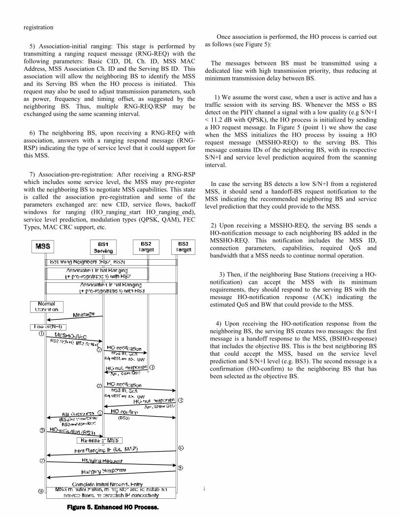
Once association is performed, the HO process is carried out
as follows (see Figure 5):
The messages between BS must be transmitted using a
dedicated line with high transmission priority, thus reducing at
minimum transmission delay between BS.
1) We assume the worst case, when a user is active and has a
traffic session with its serving BS. Whenever the MSS o BS
detect on the PHY channel a signal with a low quality (e.g S/N+I
< 11.2 dB with QPSK), the HO process is initialized by sending
a HO request message. In Figure 5 (point 1) we show the case
when the MSS initializes the HO process by issuing a HO
request message (MSSHO-REQ) to the serving BS. This
message contains IDs of the neighboring BS, with its respective
S/N+I and service level prediction acquired from the scanning
interval.
In case the serving BS detects a low S/N+I from a registered
MSS, it should send a handoff-BS request notification to the
MSS indicating the recommended neighboring BS and service
level prediction that they could provide to the MSS.
2) Upon receiving a MSSHO-REQ, the serving BS sends a
HO-notification message to each neighboring BS added in the
MSSHO-REQ. This notification includes the MSS ID,
connection parameters, capabilities, required QoS and
bandwidth that a MSS needs to continue normal operation.
3) Then, if the neighboring Base Stations (receiving a HO-
notification) can accept the MSS with its minimum
requirements, they should respond to the serving BS with the
message HO-notification response (ACK) indicating the
estimated QoS and BW that could provide to the MSS.
4) Upon receiving the HO-notification response from the
neighboring BS, the serving BS creates two messages: the first
message is a handoff response to the MSS, (BSHO-response)
that includes the objective BS. This is the best neighboring BS
that could accept the MSS, based on the service level
prediction and S/N+I level (e.g. BS3). The second message is a
confirmation (HO-confirm) to the neighboring BS that has
been selected as the objective BS.
Figure 5. Enhanced HO Process.Figure 5. Enhanced HO Process.Figure 5. Enhanced HO Process.Figure 5. Enhanced HO Process.

5
5) Once the BSHO-response is received, the MSS sends back
to the serving BS a HO indication to close all connections. Then
it should wait for a fast-ranging transmission opportunity from
BS3 in order to re-adjust transmission parameters, such as power,
frequency and timing offset.
6) The objective BS (Target BS3), upon receiving the HO-
confirm message, should provide to the MSS with a fast ranging
transmission opportunity in the following MAPs. The Ranging
IE opportunity is set using the MAC address of the MSS.
7) Since a MSS has already associated with BS3, the MSS will
send again RNG-REQ to BS3 (to re-adjust transmission
parameters in case it is necessary), using the Ranging IE
opportunity provided by BS3, (the MSS uses its MAC address to
identify the ranging opportunity).
8) The MSS should complete initial network entry with target
BS3. For this it is necessary to perform re-authorization, re-
register, re-establish connections, and re-establish IP
connectivity. In the re-authorization state, since the security
information in not expected to change, this information is
transferred from the old BS1 to the target BS3 via backbone. The
re-register process is skipped if all MSS capabilities and
management parameters were exchanged in the pre-registration
process and a service level prediction was provided to the MSS.
In the re-establish connection (service flows) process, the MSS
needs to send a dynamic service addition request (DSA-REQ) to
target BS3, in order to active the service flow. As a response,
target BS3 activate the connection, and maps this service flow
with the MSS CID (provided in the pre-registration process) and
sends back to the MSS a DSA-RSP message, indicating the
service flow activated.
Other stages, such as transfer-operational-parameters and
time-of-day establishment (carried out on MSS power on) are
skipped since none of the operational parameters nor time-of-day
is expected to change.
The last process is to re-establish IP connectivity. This process
should be carried out using Mobile IP as suggested in [7]. This is
because when an MSS which has obtained an IP address by
DHCP performs the inter-BS handoff, an ongoing session is
disconnected due to the inherent lack of mobility of DHCP
address allocation. The time taken to obtain the IP address is out
of the scope in this paper. In the following sections we describe
the simulation model and present a performance analysis on the
enhanced HO mechanism, for different traffic scenarios.
OPNET Model DescriptionOPNET Model DescriptionOPNET Model DescriptionOPNET Model Description
This section shows the key functional breakdown of the
OPNET model implementation. The model used for the
simulations consist of three cells, as shown in Figure 6. Each cell
can be partitioned into two major parts: 1) Mobile Subscriber
Stations and 2) a Base Station, as shown in Figure 6.
Mobile Subscriber Station
The Mobile Subscriber Station access node consists of a traffic
generator, a Media Access Control unit and two RF modules for
transmission and reception as pointed out in Figure 7.
The traffic generator module produces three different traffic
types according to the QoS agreed with the BS. These traffic
types are described in the following section.
Figure Figure Figure Figure 6666. Network Model. Network Model. Network Model. Network Model....
Figure Figure Figure Figure 7777. SS access node model. SS access node model. SS access node model. SS access node model....

6
The RF modules (ant_rx, from_link_rx, to_link_tx, and
ant_tx) are responsible for accepting packets from or transmitting
packes to the radio access network according to the propagation
model described in [8].
The MAC module is responsible for processing packets of
higher layers and transmitting packets to the radio access
network according to its QoS level. The MAC module uses a
primary Finite State Machine (FSM) and a secondary FSM. The
primary FSM (Figure 8) is responsible of the Initialization and
Registration procedure as well as the reception and processing of
synchronization packets, UCD, UL-MAP and DL-MAP frames
from the BS. All packets received from higher layers, are
processed at the application traffic process and sent to the
secondary FSM for transmission on the UL channel, as shown in
Figure 9.
Upon receiving a traffic packet from the Primary FSM, the
secondary FSM processes this packet according to its QoS level.
If the packet is for a Best effort service (e.i. Internet packet), the
transmit opportunity state (Tx_Opp_Proc) looks for a contention
opportunity (either in the current or in the following UL-MAP
frame) and transmits a reservation request to the BS. In case this
request results in collision with other contention transmissions,
the collision resolution (Collision_Res) state takes care to resolve
it according to the exponential backoff algorithm. If the packet
demands a UGS or rtPS service (i.e. for voice or video packets,
respectively) the transmit opportunity state sends a Dynamic
Service Addition (DSA) request to the based station, indicating
its type of service needed for this connection. If this request is
accepted, the No_Request_Outstanding process takes care of
receiving the corresponding grants and to indicate to the
Tx_Opp_Proc when to transmit these voice or video packets.
For nrtPS packets (e.g. for FTP traffic), the same procedure is
carried out as in the previous case, with the exception that the
Request_Outstanding state is now responsible for receiving the
grants from the BS. But if no-grants are allocated for this service,
these packet can still be transmitted in the radio access network
using a Best Effort service.
Base Station
The BS is in charge of MSS´s identification and to provide a
QoS level. The BS also serves as the main gate for incoming and
outgoing packets. Figure 10 shows the BS node model, which is
composed mainly of a MAC unit and one transmission and
reception module for each neighboring cell associated.
The MAC module is responsible of providing to MSS´s with
the right QoS level, and guarantees the correct transmission
opportunities. In order to provide these transmission
opportunities, the MAC module uses also two FSMs.
Basically the primary FSM, illustrated in Figure 11, performs
the following three functions: 1) takes care of the Initialization
and Registration procedure, which is done by the ranging,
rng_rcvd and rng_complete states. 2) Based on MSS´s request,
Figure Figure Figure Figure 8888. Primary SS´s. Primary SS´s. Primary SS´s. Primary SS´s FSM.FSM.FSM.FSM.
Figure Figure Figure Figure 9999. Secondary SS´s. Secondary SS´s. Secondary SS´s. Secondary SS´s FSM.FSM.FSM.FSM.
Figure Figure Figure Figure 10101010. . . . BBBBS node modelS node modelS node modelS node model....

7
the Primary FSM creates the signaling MAPs, which describe the
maintenance region (using the Mtn_MAP state), as well as
contention and reservation access (using the MAP-Time state).
3) Provides with synchronizations and UCD information to
MSSs.
All frames produced in the primary FSM, are passed to the
secondary FSM, which takes care of transmitting theses frames
in the correct DL channels as shown in Figure 12.
Simulations Analysis Simulations Analysis Simulations Analysis Simulations Analysis
In all simulations, one UL channel with a capacity of 2.8
Mbps and one DL channel with a capacity of 22.4 Mbps were
used. For the analysis, we have considered the simulation
parameters given in Table I. Two traffic scenarios were
considered for the results. These scenarios are based on the
following traffic sources.
1) Internet Traffic-IP: The Internet traffic distribution utilized
is the one introduced by the IEEE 802.14 working group [9]. The
message size distribution is as follows: 64-byte Pk. 60%, 128-
byte Pk. 6%, 256-byte Pk. 4%, 512-byte Pk. 2%, 1024-byte Pk.
25% and 1518-byte Pk. 3%. The inter-arrival times are set in
such a way that the Internet offered load per active station is 38.4
kbps at the PHY layer.
2) VoIP- G.723-UGS. This traffic type emulates a speech
codec “G.723.1”, which according to the ITU, IETF and the
VoIP Forum is the preferred speech codec for Internet telephony
applications. This codec generates a data rate of 5.3 kbps or 6.3
kbps depending on the mode, where 20-byte data packets are
generated and encoded every 30 ms. By adding all headers as
illustrated in Table II, one obtains a VoIP stream of 38.4 kbps at
the PHY layer.
For the performance analysis of the proposed HO mechanism,
we need to make sure the end-to-end delay during the handoff
procedure does not exceed 50 ms for timing critical interactive
services. Internet traffic or other delay-tolerant applications can
support larger delays (up to 1second), thus in the remaining of
this sections we will prove that our HO mechanism satisfy the
requirements for the support of different QoS agreements.
Figure 13 and 14 show the results when Internet traffic is being
transmitted. We considered a network size of 40 MSS which
produce 70% of the UL channel capacity. In Figure 13, we see
the access delays of a MSS that started the HO procedure (from
BS1 to BS2) at the simulation time of 54.6 seconds. When the
mobile station switched to BS2, the time consumed during the
HO procedure was 12 ms approximately (6 UL- MAPs). This
delay could be larger depending on the DHCP protocol, which
was not included in the simulations. Once the MSS completed
the Initialization and Registration procedures with BS2, the first
packet transmitted in this cell had a total access delay of 15.5 ms,
which is a low delay for Internet traffic. However, larger delays
Figure Figure Figure Figure 11111111. Primary . Primary . Primary . Primary BSBSBSBS´s´s´s´s FSM.FSM.FSM.FSM.
Table I. Table I. Table I. Table I. Simulation ParametersSimulation ParametersSimulation ParametersSimulation Parameters
Parameter Value
UL data rate (QPSK.) 2.816 Mbps
DL data rate (16-QAM) 22.4 Mbps
Minimum contention slots per UL-Frame 8 slots UL minislot size 16 bytes
UL-Frame Duration 2 ms =44minislots
Simulation time for each run 60s Distance from nearest/farthest SS to the BS 0.1 – 2.35 km
Reed Solomon (short grants/long grants) 6 bytes/ 10 bytes
Limit between short and long grants 245 bytes Maximum number of users in the network 200
Table Table Table Table II. II. II. II. VoIP Codec (G.723.1.VoIP Codec (G.723.1.VoIP Codec (G.723.1.VoIP Codec (G.723.1.
Frame/layer G.723.- 5.3 kbps
Frame size [ms] 30
Voice frame [bytes] 20
RTP [bytes] 12
UDP [bytes] 8
IP [bytes] 20
LLC [bytes] 3
SNAP [Bytes] 5
Ethernet MAC [bytes] 18
IEEE 802.16 MAC 6
PHY: (Prea+GB+FEC) 10+FEC
Total PacketSize 86 bytes or G=9 slots
Net rate at MAC / PHY 22.9 / 38.4 kbps
Prea = Preable, GB = Guarband, and FEC = 6* No_CodeWords
Figure Figure Figure Figure 12121212. . . . SecondarySecondarySecondarySecondary BSBSBSBS´s´s´s´s FSM.FSM.FSM.FSM.

8
(up to 100 ms) were obtained during the simulation, but these
delays are due to collisions in the contention region and the
exponential backoff algorithm which reduces the contention
transmissions opportunities for backlogged MSS.
In terms of throughput, Figure 14 shows that the effect of
changing to another BS is transparent to the MSS, since neither
throughput nor access delays suffered degradation. The average
throughput reported by this simulation was of 32 kbps, which
indicates that all packets were transmitted on time.
Results for VoIP traffic are presented in figures 15 and 16.
In Figure 15 we appreciate a constant access delay of
approximately 34 ms when the MSS moves from BS1 to BS2.
This is because the MSS can not transmit the current VoIP frame
during HO, and this voice frame is kept in the MSS buffer and
transmitted when BS2 allocates a new periodic reservation
opportunity. Thus, at the time of transmitting this voice frame,
the MSS has already received another VoIP frame, which will be
scheduled after its periodic grant interval agreed with BS2
(configured at 30 ms).
However in Figure 16, we see a small reduction in throughput
during the HO procedure due to the buffered packet. But this
reduction gradually disappears as the MSS transmits more voice
frames in BS2.
In general, although the proposed HO mechanism can support
delays under 50 ms for timing critical applications, these access
delays could be significantly reduced if we consider the
following considerations: 1) delete packets during HO for
realtime applications as long as it does not become > 3%, 2)
schedule more reservations opportunities after the HO procedure,
and 3) use the periods of silence for the transmission of buffered
packet. We are currently studying these functionalities and
results will we presented in future publications.
In addition, we did not include a discussion about the impact
of channel errors in the previous analysis. Channel errors can
degrade the QoS observed by MSS in various ways depending of
the particular service class being considered. We are also
investigating ways to overcome this problem within the proposed
HO mechanism.
CCCConclusiononclusiononclusiononclusion
In this paper we have presented the performance analysis of a
HO mechanism for IEEE 802.16e based networks. The proposed
algorithm is practical, compatible with IEEE QoS requirements,
and easy to implement. This mechanism provides a fast
Initialization and Registration procedure that guaranteed low
delays for timing critical applications, such as Voice over IP,
video and data. The performance of this HO mechanism with
mixed traffic sources, and different QoS requirement (such as
UGS, rtPS, nrtPS and BE) will be further investigated through
simulations and theoretical analysis. The results of such
performance will be provided in future publications.
ReferencesReferencesReferencesReferences
[1] B. Bing, “High-Speed Wireless Atm and Lans”, Artech
House Mobile Communications Library, Norwood, 2000.
Figure 1Figure 1Figure 1Figure 13333 Access Delay for BE trafficAccess Delay for BE trafficAccess Delay for BE trafficAccess Delay for BE traffic....
Figure Figure Figure Figure 14.14.14.14. Throughput Throughput Throughput Throughput for for for for InternetInternetInternetInternet traffictraffictraffictraffic....
Figure Figure Figure Figure 15151515 Access Delay for Access Delay for Access Delay for Access Delay for VoIPVoIPVoIPVoIP traffictraffictraffictraffic....
Figure Figure Figure Figure 16.16.16.16. Throughput Throughput Throughput Throughput for for for for VoIPVoIPVoIPVoIP traffictraffictraffictraffic....
9
[2] IEEE 802.16-2001, “IEEE Standard for Local and
Metropolitan Area Networks - Part 16: Air Interface for
Fixed Broadband Wireless Access Systems,” April 2002.
[3] IEEE 802.16-2004, “IEEE Standard for Local and
Metropolitan Area Networks - Part 16: Air Interface for
Fixed Broadband Wireless Access Systems,” October 2004.
[4] IEEE 802.16e, “IEEE Standard for Local and Metropolitan
Area Networks - Part 16: Air Interface for Fixed Broadband
Wireless Access Systems”, Amendment for PHY and MAC
for Combined Fixed and Mobile Operation in Licensed
Bands, December 2005.
[5] V. Rangel et al, “Delivery of low rate isochronous streams
over the digital video broadcasting/Digital Audio-Visual
Council cable television protocol”, IEEE Transactions on
Broadcasting, Vol. 48, Dec. 2002, pp 307-316.
[6] DOCSIS 1.1, “Data-Over-Cable Service Interface
Specifications - Radio Frequency Interface 1.1
Specification,” July 2000.
[7] T. A. Campbell, J. Gomez, S. Kim, C-Y Wan, Comparison
of IP Micromobility Protocols”, IEEE Wireless
Communications, (2002, Vol. 9, pp 72-82.
[8] Vinko Erceg et al, “An empirically based path model for
wireless channels in suburban environments,” IEEE Journal
on Selected Areas in Communications, vol. 17, Jul. 1999, pp
1205-1211.
[9] V. Rangel and R. M. Edwards, “Performance Evaluation of
Adaptive Contention Slot Allocators for CATV Networks
based on the European Cable Communications Protocol
DVB/ DAVIC”, Journal of the SCTE, vol. 24, Sep. 2002, pp
24-30.