Perfecting Railcar Performance - minerent.com · 6 7 Fig. 1 TCC Style Standard Travel MODEL TOP CAP...
35
Version 4.0, Printed 3/09 08-MEM-60-5.5M © 2009 Miner Enterprises, Inc. Customer Service 1-630-232-3000 Perfecting Railcar Performance Version 4.0 3/09
Transcript of Perfecting Railcar Performance - minerent.com · 6 7 Fig. 1 TCC Style Standard Travel MODEL TOP CAP...

Version 4.0, Printed 3/09 08-MEM-60-5.5M © 2009 Miner Enterprises, Inc.
Customer Service 1-630-232-3000
Perfecting Railcar Performance
Version 4.0 3/09

TABLE OF CONTENTS
OverviewIntroduction ...................................................................... 2List of Illustrations ........................................................... 2
TecsPak® Constant Contact Side BearingsGeneral Description ......................................................... 4Product Identification ....................................................... 6Installation
Set Up Height ....................................................... 20Car Body Wear Plate ............................................ 25Side Bearing Installation – Bolt-on Style ............ 27Standard Travel Retrofit Installation .................... 30Long Travel Retrofit Selection Guide.................... 31Long Travel Retrofit Installation ........................... 35TecsPak® Pads ....................................................... 44
InspectionSet Up Height........................................................ 45General .................................................................. 50Top Cap Wear Indicators ...................................... 50TecsPak® Pad Free Height Measurement ............ 52
Draft GearsGeneral Description ....................................................... 56Procedure for Determining Serviceability
of Miner Draft Gears............................................. 58
Brake BeamsGeneral Description ....................................................... 64Inspection ....................................................................... 64Strut Hand Change Procedure ....................................... 66

3
TecsPak® Constant Contact (TCC) Side Bearings (con’t.)
Fig. 14 TCC-45 LTRB..............................................................................19Fig. 15 Caliper Measurement ............................................................. 20Fig. 16 Block Style Retrofit Set Up Height (LTLP and LTLP-B) .......... 21 Fig. 17 Block Style Retrofit Set Up Height Gage............................... 23Fig. 18 TCC-45/60 LTR Solid Stop Installation .................................. 35Fig. 19 TCC-45 LTLP Pocket Installation............................................. 37Fig. 20 TCC-45 LTLP-B ......................................................................... 39Fig. 21 TCC-45 LTRB Housing Securement........................................ 40Fig. 22 Welding Procedure – Cross Section...................................... 41Fig. 23 Pocket Size Adjustment .......................................................... 43Fig. 24 Set Up Height Field Inspection Gage..................................... 45Fig. 25 Standard Set Up Height Chart – Inspection ......................... 46Fig. 26 Standard Set Up Height Indicators – Inspection.................. 47Fig. 27 Block Style Retrofit Set Up Height Chart – Inspection ........ 49Fig. 28 Block Style Retrofit Set Up Height Indicators – Inspection...... 49Fig. 29 TCC-IV Wear Indicator ............................................................ 51Fig. 30 TCC-45/60 LTR & LTRB Wear Indicator ................................. 51Fig. 31 TCC-45 LTLP-B Wear Indicator ............................................... 51Fig. 32 TCC-45 LTLP Wear Indicator................................................... 51Fig. 33 TecsPak® Pad Free Height Measurement ............................ 52
Draft Gears
Fig. 34 Crown SE™ and Crown SG™ In-Car Inspection ..................... 58Fig. 35 Crown SE™ and Crown SG™ Out-of-Car Inspection............... 59Fig. 36 TF-880™ In-Car Inspection ....................................................... 60Fig. 37 TF-880™ Out-of-Car Inspection ............................................... 61Fig. 38 SL-76™ In-Car Inspection ........................................................ 62Fig. 39 SL-76™ Out-of-Car Inspection ................................................ 63
Brake Beams
Fig. 40 Miner Series 2008™ Brake Beam - #18 ................................. 65Fig. 41 Miner Series 2008™ Brake Beam - #24 ................................. 65Fig. 42 Miner Series 2008™ Brake Beam Strut Change ................... 67
2
OVERVIEW
INTRODUCTION
This convenient Installation and Inspection Pocket Guideprovides important technical information regardingMiner’s full-line of TecsPak® constant contact side bearings, draft gears and brake beams. In it you will find sections covering product identification, installation,and inspection.
LIST OF ILLUSTRATIONS
TecsPak® Constant Contact (TCC) Side Bearings
Fig. 1 TCC Style ................................................................................... 6Fig. 2 TCC-4500 RA ............................................................................. 7Fig. 3 TCC-II.......................................................................................... 8Fig. 4 TCC-III LT .................................................................................... 9Fig. 5 TCC-III ST ................................................................................. 10Fig. 6 TCC-III RA ............................................................................... 11Fig. 7 TCC-IV LT ................................................................................. 12Fig. 8 TCC-8000 RL............................................................................ 13Fig. 9 TCC-8000 RS ........................................................................... 14Fig. 10 TCC-45 LTR .............................................................................. 15Fig. 11 TCC-60 LT ................................................................................ 16Fig. 12 TCC-45 LTLP............................................................................. 17Fig. 13 TCC-45 LTLP-B ......................................................................... 18

5
The second generation of bearings, TCC-II-25, -35, -60 and -80S, are all Long Travel (LT).
The third generation of bearings, TCC-III-30, -45, -60 and -80, are available as either Standard Travel (ST), Long Travel (LT) orRoller Assist (RA) models.
The fourth generation of bearings, TCC-IV-30, -45, -60 and -80, are all Long Travel (LT).
The TCC-8000 RS retrofit bearings are designed to fit into a single roller cage and are Standard Travel (ST).
The TCC-45 LTR and TCC-60 LTR are designed to fit into a doubleroller cage and are Long Travel (LT).
The TCC-45 LTLP is designed to fit into a low profile small pocketand the TCC-45 LTLP-B is designed to fit into a large pocket lowprofile block style side bearing pocket and are both Long Travel (LT).
The TCC-45 LTRB is designed to fit into a standard height blockstyle side bearing pocket and is Long Travel (LT).
TECSPAK CONSTANT CONTACT (TCC)SIDE BEARINGS
4
GENERAL DESCRIPTION
Miner’s TecsPak® constant contact side bearings feature a unique metal-on-metal design enabling them to provide a more stable ride by instantaneously counteracting the rotational motion of truck hunting. Their superior designbreaks friction and dissipates energy before truck huntingimpacts car stability and component wear. When installingand/or inspecting any of Miner’s side bearings, it is critical to identify the proper bearing and its components.Miner side bearings include: TCC, TCC-II, TCC-III, TCC-IV and Retrofit models. Please refer to the ProductIdentification section (Page 6) before any installation and/or inspection procedures.
Miner’s TecsPak® constant contact side bearings are available in a range of preloads and designs. The model name will designate the side bearing preload in pounds (e.g. TCC-8000) or hundreds of pounds (e.g. TCC-IV-60 LT). Some models are also available in:
Standard Travel 5/16” travel from 5-1/16” set up heightRoller Assist 5/16” travel from 5-1/16” set up heightLong Travel 5/8” travel from 5-1/16” set up height
The first generation of Miner TCC side bearings, TCC-2600, -4500 and -8000, are Standard Travel (ST). The TCC-4500 RA is a Roller Assist model.
®
76
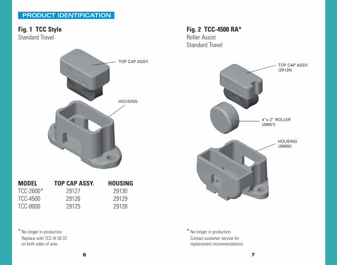
Fig. 1 TCC StyleStandard Travel
MODEL TOP CAP ASSY. HOUSINGTCC-2600* 29127 29130TCC-4500 29126 29129TCC-8000 29125 29128
Fig. 2 TCC-4500 RA*Roller AssistStandard Travel
* No longer in production. Contact customer service for replacement recommendations.
* No longer in production. Replace with TCC-III-30 ST on both sides of axle.
TOP CAP ASSY.
HOUSING
TOP CAP ASSY.(29126)
4”x 2” ROLLER(29651)
HOUSING(29650)
PRODUCT IDENTIFICATION

98
Fig. 3 TCC-II*Long Travel
MODEL REPLACE WITH:TCC-II-25 TCC-III-30 LT on both sides of axleTCC-II-35 TCC-III-45 LT on both sides of axleTCC-II-60 TCC-III-60 LT on both sides of axleTCC-II-80S TCC-III-80 LT on both sides of axle
Fig. 4 TCC-III LTLong Travel
MODEL HOUSING PADTCC-III-30 LT 40141 T-0305TCC-III-45 LT 40142 T-0300TCC-III-60 LT 40143 T-0306TCC-III-80 LT 40144 T-0307
TOP CAP(40136)
PAD
HOUSING
*No longer in production.

TOP CAP(40136)
PAD
HOUSING
TOP CAP(40136)
PAD
HOUSING
ROLLER(29792)
BASE PLATE(29794)
1110
Fig. 5 TCC-III STStandard Travel
MODEL HOUSING PADTCC-III-30 ST 40137 T-0305TCC-III-45 ST 40138 T-0300TCC-III-60 ST 40139 T-0306TCC-III-80 ST 40140 T-0307
MODEL HOUSING PADTCC-III-30 RA 40318 T-0305TCC-III-45 RA 40319 T-0300TCC-III-60 RA 40320 T-0306TCC-III-80 RA 40321 T-0307
Fig. 6 TCC-III RARoller AssistStandard Travel
1312
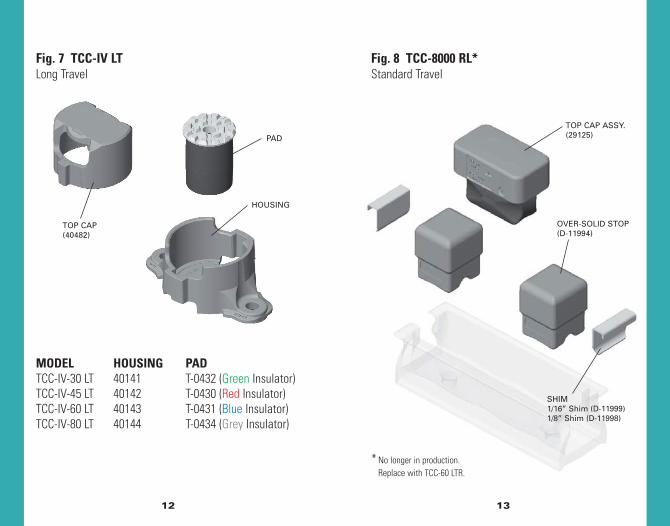
Fig. 7 TCC-IV LTLong Travel
Fig. 8 TCC-8000 RL*Standard Travel
MODEL HOUSING PADTCC-IV-30 LT 40141 T-0432 (Green Insulator)TCC-IV-45 LT 40142 T-0430 (Red Insulator)TCC-IV-60 LT 40143 T-0431 (Blue Insulator)TCC-IV-80 LT 40144 T-0434 (Grey Insulator)
TOP CAP(40482)
PAD
HOUSING
TOP CAP ASSY.(29125)
OVER-SOLID STOP(D-11994)
SHIM1/16” Shim (D-11999)1/8” Shim (D-11998)
* No longer in production. Replace with TCC-60 LTR.

1514
Fig. 9 TCC-8000 RSStandard Travel
Fig. 10 TCC-45 LTRLong Travel
TOP CAP ASSY.(40624)
SOLID STOP(40625)
1/8” SHIM(D-11998)
1/16” SHIM(D-11999)
TOP CAP ASSY.(29125)
OVER-SOLID STOP(D-11997)
SHIM1/16” Shim (D-11999)1/8” Shim (D-11998)

1716
Fig. 11 TCC-60 LTRLong Travel
Fig. 12 TCC-45 LTLPLong Travel
TOP CAP ASSY.(40575)
TOP CAP ASSY.(40570)
SMALL WEDGE(40672)
SOLID STOP(40576)
1/16” SHIM(D-11999)
1/8” SHIM(D-11998)
HOUSING(40569)
18 19
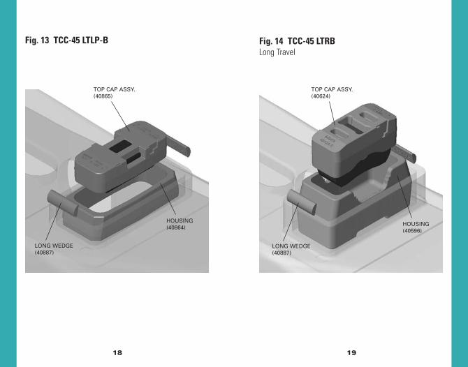
Fig. 14 TCC-45 LTRBLong Travel
TOP CAP ASSY.(40865)
HOUSING(40864)
LONG WEDGE(40887)
Fig. 13 TCC-45 LTLP-B
TOP CAP ASSY.(40624)
HOUSING(40596)
LONG WEDGE(40887)

2120
Block Style Retrofit Set Up Height
INSTALLATION
Set Up HeightThe set up height, or the vertical distance between the carbody side bearing wear plate and the housing mountingsurface, should be measured using inside calipers and asteel rule. A twelve-inch steel straightedge is helpful for checking the flatness of the body wear plate and thebolster mounting surface.
Standard Set Up Height
Alternative Set Up HeightMiner side bearings allow greater flexibility in the set upheight. On some articulated intermodal cars, at the malelocation of the articulated connection, the side bearingcan have a set up height of 5-3/16”, ± 1/16”. On selectedautorack cars, the long travel side bearing can have a set up height of 5-1/16”, ± 1/8”. (Refer to owners’instructions, or stenciling, on these types of cars.) If a newelastomeric horizontal center bowl liner is used, it is rec-ommended that you add 1/16” to the nominal dimension.
Fig. 15 Caliper Measurement
Models Installation or Adjustment*^
TCC, TCC II, TCC III,TCC IV, TCC 45/60 LTR
Metal Liner New Non-Metallic Liner or Lube Disc
Nominal Tolerance Nominal Tolerance5-1/16 ± 1/16 5-1/8 ± 1/16
Range Max: 5-1/8 Max: 5-3/16Min: 5 Min: 5-1/16
* Installation and adjustment should be done in empty condition on level track^ Male end of articulated connected cars may have a nominal value of 5-3/16
CAR BODY WEAR PLATE
Fig. 16 Block Style Retrofit Set Up Height
Models Installation or Adjustment
TCC 45 LTLP,TCC 45 LTLP-BTCC 45 LTRB
Metal Liner New Non-Metallic Liner or Lube Disc
Nominal Tolerance Nominal Tolerance5/8 ± 1/16 11/16 ± 1/16
Range Max: 11/16 Max: 3/4Min: 9/16 Min: 5/8
CAR BODY WEAR PLATE
2322
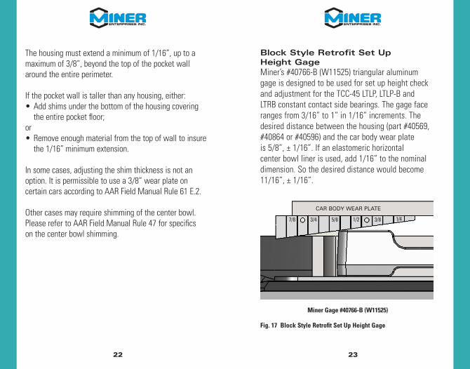
Block Style Retrofit Set Up Height GageMiner’s #40766-B (W11525) triangular aluminumgage is designed to be used for set up height checkand adjustment for the TCC-45 LTLP, LTLP-B and LTRB constant contact side bearings. The gage faceranges from 3/16” to 1” in 1/16” increments. Thedesired distance between the housing (part #40569,#40864 or #40596) and the car body wear plate is 5/8”, ± 1/16”. If an elastomeric horizontal center bowl liner is used, add 1/16” to the nominal dimension. So the desired distance would become11/16”, ± 1/16”.
The housing must extend a minimum of 1/16”, up to amaximum of 3/8”, beyond the top of the pocket wallaround the entire perimeter.
If the pocket wall is taller than any housing, either:• Add shims under the bottom of the housing covering
the entire pocket floor;or• Remove enough material from the top of wall to insure
the 1/16” minimum extension.
In some cases, adjusting the shim thickness is not anoption. It is permissible to use a 3/8” wear plate on certain cars according to AAR Field Manual Rule 61 E.2.
Other cases may require shimming of the center bowl.Please refer to AAR Field Manual Rule 47 for specifics on the center bowl shimming.
Fig. 17 Block Style Retrofit Set Up Height Gage
1/43/81/25/83/47/8
CAR BODY WEAR PLATE
Miner Gage #40766-B (W11525)

2524
Car Body Wear PlateThe car body wear plate must conform to AAR standard S-235. The car body side bearing wear plate must besmooth. Any weld spatter, heavy rust or surface projectionsmust be removed by grinding. Fastener heads must besmooth and flush below wear plate surface, and the fasteners securely tightened. Plates with surface variationsbetween fastener holes greater than 1/8”, or greater than1/16” over any 4” space between the fastener holes, mustbe replaced. Surface must be reasonably parallel to sidebearing mounting surface. Variations should not exceed1/16” across width or 1/8” end-to-end.
Minimum Wear Plate Size
MODEL MINIMUM SIZETCC, TCC-II, TCC-III LT, TCC-III ST, 4” wide by 12” longTCC-IV LT, TCC-45 LTLP-BTCC RA, TCC-III RA Consult car builder
Truck Centers Min. Width Min. LengthLess than or equal to 70’ 4” 12”Over 70’ to 82’ 4” 14”Over 82’ to 94’ 4” 16”Greater than 94’ 4” 18”
To check the set up height, put flat end of gage up to the car body wear plate and slide the gage in untilit contacts the housing. If the gap is below 5/8” then remove the correct amount of shims and if thegap is above 5/8” add the correct amount of shims.The gage has 1/8” increments lined and labeled with 1/16” increments lined, but not labeled. Thethickness of the gage is 1/8” and can be used as the smallest measurement increment on the gage.Simply turn the gage flat and put one side againstthe wear plate and slide the gage in.
TCC-45 LTR, LTRB, LTLP and TCC-60 LTR
Please refer to AAR Field Manual Rule 61 for more detailedinformation regarding body wear plates.

2726
Side Bearing Installation – Bolt-on StyleThe housing should be mounted to the truck bolster padutilizing one of the following fasteners:
Acceptable fasteners on all models EXCEPT the TCC-III RA:• Camcar standard dome head fastener (reference part
#794-20100-130). • Huck fastener (reference part #C71LR-BR24-28/32
and #3LC-2R24GL). • 7/8”-9 Grade 5 or better HEX head bolt with
self-locking nut. Torque:
– Dry: 375-425 ft.-lbs. (Produces a clamping force of 20,000-30,000 lbs. per bolt).
– Waxed or well lubricated: 280-320 ft.-lbs. (Roughly 25% reduction from dry values).
Acceptable fasteners for the TCC-III RA ONLY:• Camcar flat head fastener (reference part
#784-20156-140/160). • 7/8”-9 Grade 5 or better FLAT head bolt with
self-locking nut. Torque:
– Dry: 375-425 ft.-lbs. (Produces a clampingforce of 20,000-30,000 lbs. per bolt).
Lubrication (For new cars only)Due to the stiffness of new car trucks and other components (“new car syndrome”), it is recommendedthat the frictional resistance between the car bodywear plate and the side bearing top cap be held to aminimum during the break in period. In order to reducethe friction during the initial break in, apply a thin coat of lubricant (No. 2 lithium grease or equal) to thetop surface of the top cap. Do not use Molybdenumdisulfide type lubricants since they are too permanent.The lubricant is for initial break in period only andafter a short period of service will be wiped away and the side bearing will function to provide properhunting control. Some recommended lubricants areTexaco Multifak 2, Amoco Amolith EP-2, Citgo H-2,Mobil Grease 2, Shell Alvania 2 or Exxon Lidok EP-2.
Warning – Lubrication to be applied in new carproduction only.
Miner does not recommend lubrication when new side bearings are applied for maintenance.
2928
TCC-IV LTEach TCC-IV pad is supplied with a color-coded insulatorattached to the top. Each pad assembly is color coded asfollows: TCC-IV-30 (Green), TCC-IV-45 (Red), TCC-IV-60(Blue) and TCC-IV-80 (Grey). The TecsPak® pad insidediameter should easily slide onto the post inside thehousing with the insulator facing up. There is a 1/32”clearance between the post diameter at bottom and theinside diameter of the pad. Therefore, if the clearance isgreater than 1/32”, or it is difficult to assemble the padover the housing post, the wrong pad has been applied.The top cap post should slide easily into the insulator/pad.The car body wear plate must cover the 3”-wide flat onthe top cap. (Reference Fig. 7, Page 12)
– Waxed or well lubricated: 280-320 ft.-lbs. (Roughly 25% reduction from dry values).
Warning – Remove all C-Pep pads when installingconstant contact side bearings.
TCCInstall top cap assembly into housing with the metal cap up. Ensure that top cap end slots mate with housinglugs. (Reference Fig.1 and 2, Pages 6 and 7)
TCC-III LT/ST/RAThe TecsPak® pad inside diameter should easily slideonto the post inside the housing. There is a 1/32” clearance between the post diameter at bottom and theinside diameter of the pad. Therefore, if the clearance is greater than 1/32”, the wrong pad has been applied.The top cap post should slide easily into the pad. Withthe TCC-III RA, install the base plate into the rectangularsection of the housing with the writing facing up, thenplace the roller on it. The car body wear plate must coverthe 3”-wide flat on the top cap. (Reference Figs. 4-6,Pages 9-11)

3130
Standard Travel Retrofit Installation
TCC-8000 RL/RSTCC-8000 RL – Miner recommends replacing the TCC-8000 RL with the TCC-60 LTR.
TCC-8000 RS – Place the over-solid stops in the housing with the legs facing the ends of the housing.Insert the 8000 top cap between the stops and check thelongitudinal clearance, which should be snug, but nottight. Nominal is less than 1/16” end-to-end with shimsin place. The two shims are provided in different sizes sothey can be used if needed. On a newer housing, youmay need only one shim. It is not necessary to use bothshims on all housings. (Reference Fig. 9, Page 14)
Long Travel Retrofit Selection Guide
Standard HeightTCC-45 LTRTCC-60 LTR
Set Up Height5-1/16”, +/- 1/16”
Cage SizeOnly for use in 688-B Double Roller Cages
Minimum Car Body Weight
TCC-45 LTR 21,176 lbs.TCC-60 LTR 28,235 lbs.
Installation instructions available on Page 35.

32 33
Long Travel Retrofit Selection Guide
Low ProfileTCC-45 LTLP
Pocket Height1.5”- 2.5” Miner housing MUST extend 1/16”
to 3/8” above pocket wall. Shim under Miner housing if pocket is 2” or taller.
Min. Pocket Width3.25” Install with housing shifted toward
the outboard side.
Min. Pocket Length8.13” Optimal inside length for shimming
should be 8.25”.
Max. Pocket Length
Shimming on the inside ends of the housing will be needed if the inside length is greater than 8.68”.
Installation instructions available on Page 37.
IF POCKET HEIGHT IS BETWEEN 2.5” AND 3.13”, CALLMINER FOR RECOMMENDATION.
Long Travel Retrofit Selection Guide
Low ProfileTCC-45 LTLP-B
Pocket Height1.5”- 2.5” Miner housing MUST extend 1/16”
to 3/8” above pocket wall. Shim under Miner housing if pocket is 2” or taller.
Min. Pocket Width4.25” Install with housing shifted toward
the outboard side.
Min. Pocket Length9.25” Optimal inside length for shimming
should be 9.38”.
Max. Pocket Length
Shimming on the inside ends of the housing will be needed if the inside length is greater than 9.63”.
Installation instructions available on Page 39.
IF POCKET HEIGHT IS BETWEEN 2.5” AND 3.13”, CALLMINER FOR RECOMMENDATION.

3534
Long Travel Retrofit Selection Guide
Standard HeightTCC-45 LTRB
Pocket Height3.13”- 4.25”
Min. Pocket Width4.13” Install with housing shifted toward
the outboard side.
Min. Pocket Length9.00” Optimal inside length for shimming
should be 9.13”.
Max. Pocket Length
Shimming on the inside ends of the housing will be needed if the inside length is greater than 9.25”.
Installation instructions available on Page 40.
IF POCKET HEIGHT IS BETWEEN 2.5” AND 3.13”, CALLMINER FOR RECOMMENDATION.
Long Travel Retrofit Installation
TCC-45/60 LTRPreparation – Remove the double rollers and clean the insideof the cage of any foreign material. The existing cage must befree of cracks, tears and deformation. The inside edges of the gibs at each end must be free of upset metal that wouldprevent the over-solid stops or shims from fitting flush againstthe inside of the gibs. The heads of the cage fasteners must be flush or below the contour of the bottom of the cage. Cage fasteners must be tight.
Solid Stop Installation – The assembly requires that the two solid stops be placed on either end of the cage with the legs facing outward and orientated with the marked topside facing up.
Shim Adjustment – Install a 1/16” shim on both ends. Afterinstalling the top cap, push one solid stop towards the oppositeend of the housing. If the resulting gap between the shim andsolid stop is greater that 1/16”, install thicker, 1/8” shim onone end and recheck. If the gap is too small and does notallow the cap to move freely up and down, remove shims asnecessary. (Reference Figs. 10 and 11, Pages 15 and 16)
Fig. 18 TCC-45/60 LTR Solid Stop Installation
MAXIMUM 1/16” GAP
PUSH SOLID STOP TO OPPOSITE END
SOLID STOPVERTICAL DIRECTION
SOLID STOP LEGSFACE TOWARD
CAGE GIBS

3736
TCC-45 LTLP Installation1. Shift the housing in the pocket to the outboard side
of the bolster.2. Center housing along its length in the pocket and
insert small wedges in both ends.3. Insure that the flat side of the wedge is against the
Miner housing and the rounded side is against the pocket wall.
4. Insure that the wedges on the ends are approximatelyat the same height and that all wedges do not extend beyond the housing top surface.
5. Securing the housing to the pocket requires welding.See welding requirements on Page 41.
Fig. 19 Pocket Installation POCKET
OUTBOARD SIDE OF BOLSTER
TCC-45 LTLPPreparation - Remove the metal block and clean the pocket of any foreign material. Inspect the pocket forcracks or any other damage, and repair if necessary. Insure that the pocket bottom and end walls are relatively smooth and free of any weld spatter, bumps, etc. Remove all C-Pep pads when installing constant contact side bearings.
Housing Placement - There are many different sizes of pockets that are currently in service. Smaller to mediumsized pockets (see below dimensions) may only require two small wedges.
Miner recommends using the TCC-45 LTLP-B forpockets equal to or larger than 9-1/4” x 4-1/4”.
The small wedges are designed to install the TCC-45 LTLPinto the following smaller pocket dimensions:
Minimum Inside Length: 8-1/8”Maximum Inside Length: 8-11/16” Minimum Inside Width: 3-1/4”
3938
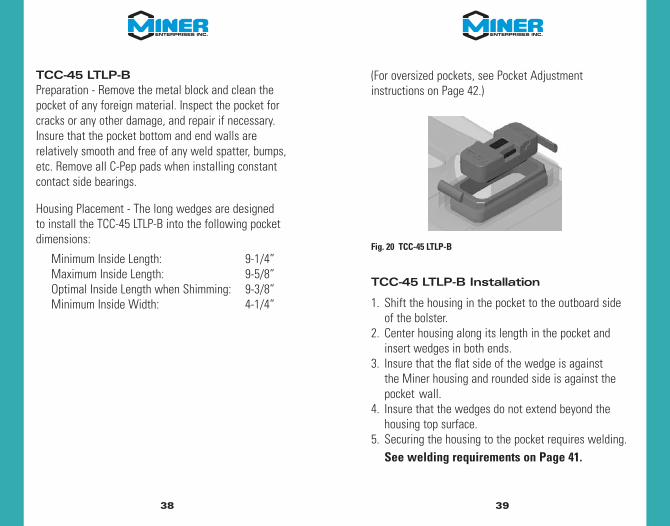
TCC-45 LTLP-BPreparation - Remove the metal block and clean thepocket of any foreign material. Inspect the pocket forcracks or any other damage, and repair if necessary.Insure that the pocket bottom and end walls are relatively smooth and free of any weld spatter, bumps,etc. Remove all C-Pep pads when installing constantcontact side bearings.
Housing Placement - The long wedges are designed to install the TCC-45 LTLP-B into the following pocketdimensions:
Minimum Inside Length: 9-1/4” Maximum Inside Length: 9-5/8” Optimal Inside Length when Shimming: 9-3/8” Minimum Inside Width: 4-1/4”
(For oversized pockets, see Pocket Adjustment instructions on Page 42.)
TCC-45 LTLP-B Installation
1. Shift the housing in the pocket to the outboard side of the bolster.
2. Center housing along its length in the pocket and insert wedges in both ends.
3. Insure that the flat side of the wedge is against the Miner housing and rounded side is against the pocket wall.
4. Insure that the wedges do not extend beyond the housing top surface.
5. Securing the housing to the pocket requires welding. See welding requirements on Page 41.
Fig. 20 TCC-45 LTLP-B

FILL GROOVE WITH 70KSI MINIMUM TENSILE STRENGTH WELD MATERIAL
4140
Fig. 21 TCC-45 LTRBHousing Securement
TCC-45 LTRBPreparation - Remove the metal block and clean the pocketof any foreign material. Inspect the pocket for cracks or anyother damage, and repair if necessary. Insure that the pocketbottom and end walls are relatively smooth and free of anyweld spatter, bumps, etc. Remove all C-Pep pads wheninstalling constant contact side bearings.
Housing Placement – The assembly only requires one set ofwedges. Center housing in pocket and insert proper wedgesin both ends.
1. Make sure that the flat side of the wedge is against the Miner housing and the rounded side is against the pocket.
2. Insure that both wedges are approximately at the same height and that they do not extend beyond the housing top surface.
3. Securing the housing to the pocket requires welding. See welding requirements on Page 41.
Warning – Do not weld directly on Miner housing.
Install top cap assembly into housing with the metal cap up. (Reference Fig.14, Page 19)
Housing Securement Welding Procedure(TCC-45 LTLP, LTLP-B AND LTRB)
Remove the top cap assembly from housing prior to welding.
Warning – Do not weld near the top cap assembly.
Warning – Do not weld directly to either Miner housing ortop cap.
Flare bevel groove weld wedge to pocket wall (1-1/2” minimum length) with 70-ksi minimum tensile strength weld material. If the wedge is below the pocket wall, add reinforcement fillet weld on top. Insure that weld and pocket wall are at least 1/16” below housing wall. All surface preparation and welding must comply with ANSI/AWS D15.1 Railroad Welding Specification – Cars and Locomotives, latest edition, including preheat when required.
POCKET WALL
WEDGE
Fig. 22 Welding Procedure– Cross Section
4342
Pocket Size AdjustmentSome pockets may be slightly larger than the TCC-45 LTLPor LTLP-B are designed to fit into. For these applications,follow the procedures below.
TCC-45 LTLPInside Length - If the wedges hit the pocket floor beforecontacting the end wall (inside length greater than 8-11/16”), shim application is required. Optimal insidelength after shimming should be 8-1/4”. Fabricate theshim so that it is 1/4” shorter than the pocket wall andno wider than the flat portion of the end wall. Leaveenough room on the shim width for welding. Fillet weldthe shim to one end of the pocket using 70-ksi minimumtensile strength weld material.
Inside Width - If the addition of wedges to the inboardside of the pocket still leaves a gap of greater than 1/8” (inside width greater than 4-5/16”), please use theTCC-45 LTLP-B. Estimate the shim thickness needed to reduce the gap between wedge and the pocket wall to 1/8” or less. Fabricate the shim so that it isapproximately 1/4” shorter than the pocket wall and no longer than the flat portion of the pocket side wall.Leave enough room on the shim length for welding. Fillet weld the shim to the outboard side of the pocketusing 70-ksi minimum tensile strength weld material.
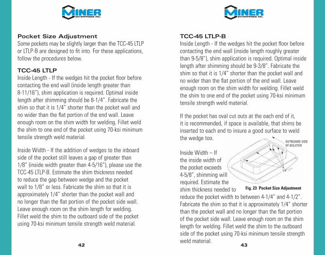
Fig. 23 Pocket Size Adjustment
1/4”
OUTBOARD SIDEOF BOLSTER
TCC-45 LTLP-BInside Length - If the wedges hit the pocket floor beforecontacting the end wall (inside length roughly greaterthan 9-5/8”), shim application is required. Optimal insidelength after shimming should be 9-3/8”. Fabricate theshim so that it is 1/4” shorter than the pocket wall andno wider than the flat portion of the end wall. Leaveenough room on the shim width for welding. Fillet weldthe shim to one end of the pocket using 70-ksi minimumtensile strength weld material.
If the pocket has oval cut outs at the each end of it, it is recommended, if space is available, that shims beinserted to each end to insure a good surface to weldthe wedge too.
Inside Width – If the inside width of the pocket exceeds 4-5/8”, shimming will required. Estimate the shim thickness needed to reduce the pocket width to between 4-1/4” and 4-1/2”.Fabricate the shim so that it is approximately 1/4” shorterthan the pocket wall and no longer than the flat portionof the pocket side wall. Leave enough room on the shimlength for welding. Fillet weld the shim to the outboardside of the pocket using 70-ksi minimum tensile strengthweld material.

4544
TecsPak® PadsThe TecsPak® pad must not be exposed to temperatureenvironments higher than 200˚ F., or 175˚ F. for extendedperiods of time (2-3 hours). After the side bearings havebeen installed, and the car body lowered onto the trucks,the set up height will probably be greater than the original set up. Initial set needs to take place and thisheight will gradually reach the designed set up height. At temperatures lower than 40˚ F., this may require atleast 24 hours. For this reason, the TecsPak® pads should be maintained at a 40˚ F. or higher temperature for at least 24 hours before assembly on a car.
Remove TecsPak® pads and top cap assemblies prior to welding. Allow ample time for cooling before replacingpad or top cap assembly.
Warning – Do not weld near TecsPak® pads.
4-7/8”
CAR BODY WEAR PLATE
5-1/8”
INSPECTION
For side bearing wear limits and cause for renewal,please refer to Rule 62 of the Field Manual of the AAR Interchange Rules.
Set Up HeightThe set up height is the vertical distance between the car body side bearing wear plate and the housingmounting surface. It should be measured with an empty car positioned on level track. For field and yard inspections, it is acceptable to use Miner Gage#29417-B (W11465) for low set up height inspections. It is recommended that whenever possible the set up height should be measured by using a set of insidecalipers and a steel rule.
Fig. 24 Miner Gage #29417-B (W11465)

4746
Inspection Set Up Height Criteria
Fig. 25 Inspection Set Up Heights
Fig. 26 Standard Set Up Height Indicators
Models Shop or Repair Track Inspection**
TCC, TCC II,TCC III, TCC IVTCC 45/60 LTR
Nominal Tolerance5-1/16 ± 1/8
Range Max: 5-3/16 Min: 4-15/16
Models Field or Yard Inspection**
TCC, TCC II,TCC III, TCC IVTCC 45/60 LTR
Nominal Tolerance5-1/16 ± 3/16
Range Max: 5-1/4 Min: 4-7/8
Some models include cast-in markings to assist in a rough estimate of the set up height.
5-1/8”
5-1/8”
5-1/8”
4-7/8”
4-7/8”
BOTTOM EDGE OFTCC-III OR TCC-IV TOP CAP
NEWER STYLE LONGTRAVEL HOUSING
TCC-III TOP CAP
TCC LTR TOP CAP
DOUBLE ROLLER CAGE
OLD STYLE TCC-III HOUSING
5”
** Permissible to use the Sum of Pairs Method.
If the values fall out of this range and need adjustment, refer back to Page 20.

2-7/16”
5-1/8”
TCC-45 LTRBHOUSING
4-7/8”
2-11/16”
LTLP TOP CAPTCC-45 LTR TOP CAP(PARTING LINE)
LTLP HOUSING
4948
Alternative Set Up HeightFor articulated cars, consult RP-899 - “Car Owner'sManual for the Inspection and Maintenance of DoubleStack Container Cars” in section I of the of the AARManual of Standards and Recommended Practices. For cars with nominal set up heights that are not 5-1/16” and are not block style retrofits, refer to owners’ instructions.
Inspection of Block Style Retrofit Set Up HeightThe set up height on block style side bearings can be difficult to measure because the pocket limits access to referencing the bolster pad. Therefore the set upheight on the TCC-45 LTLP and TCC-45 LTLP-B should be measured between the top of the housing and the underside of the car body wear plate. Because the housing acts as a solid stop, this measurement shouldbe 5/8”, +1/16”.
Fig. 27 Block Style Retrofit Set Up Heights
Fig. 28 Block Style Retrofit Set Up Height Indicators
Some models include cast-in markings to assist in arough estimate of the set up height.
** Permissible to use the Sum of Pairs Method
Models Shop or Repair Track Inspection**
TCC 45 LTLP,TCC 45 LTLP-BTCC 45 LTRB
Nominal Tolerance5/8 ± 1/8
Range Max: 3/4 Min: 1/2
Models Field or Yard Inspection**
TCC 45 LTLP,TCC 45 LTLP-BTCC 45 LTRB
Nominal Tolerance5/8 ± 1/8
Range Max: 13/16 Min: 7/16

5150
GeneralYard or Field – The housing and top cap castings mustbe free of cracks and be securely fastened to the truckbolster. Do not shop a car because of TCC-II bolt wear.The bolt wear does not affect the safe operation of the car.
Shop or Repair Track – Inspect metal parts for cracks and the TecsPak® pads for melting; replace in kind. For optimal performance, it is recommended if theclearance between the top cap OD and the housing ID is greater than 1/8”, install new top cap and re-measure. If the clearance is still greater than 1/8”, replace both top cap and housing.
Top Cap Wear IndicatorsSome of Miner’s top caps have built-in wear indicatorsthat will allow the inspector to determine if the top cap has been worn down due to contact with the carbody wear plate. If the indicator has been worn downflush to the bottom surface the top cap will need to be replaced.
The models that have this feature are the TCC-IV, TCC-45 LTR, LTRB, LTLP, LTLP-B, and the TCC-60 LTR.
Fig. 29 TCC-IV Wear Indicator
Fig. 30 TCC-45/60 LTR & LTRB Wear Indicator
Fig. 31 TCC-45 LTLP-B Wear Indicator
Fig. 32 TCC-45 LTLP Wear Indicator
TCC-IV WEAR INDICATOR
TCC-45 LTLP-B WEAR INDICATOR
TCC-45/60 LTR & LTRB WEAR INDICATOR
TCC-45 LTLP WEAR INDICATOR

TecsPak® Pad Free Height MeasurementShop or Repair Track – The spring used in Miner constant contact side bearings is called a TecsPak®
pad. With use, the pads can lose some of their preload. For optimal performance, the free height of the pad should be measured to determine suitability for continued service.
TCCTo determine if the TecsPak® elastomer pad has sufficient preload, measure the free height of the top cap assembly. To do this, remove the top cap assemblyfrom the housing, then allow two hours for the pad tostabilize. For optimal performance, it is recommendedthe top cap assembly be greater than the followingheights:
TCC-2600 4-5/8” TCC-4500 4-3/4” TCC-8000 4-1/2”
Fig. 33 TecsPak® Pad Free Height Measurement
5352
TCC-IIThe TCC-II side bearings are pre-assembled at the factoryand normally should not need to be disassembled. TheTecsPak® pads are contained within the housing and topcap. The top cap is held in position by two retaining bolts,thus maintaining approximately 2,000 lbs. on the pads whenthe side bearing is at free height (5-7/8”).
Warning - Under no circumstances should the retaining bolts be removed unless the side bearing has been compressed to relieve the load on the bolts.
Both sides of the bolts will develop a flat spot after a certainamount of service. If the bolts are broken, missing, or wornto less than 1⁄4” in thickness, the entire assembly will needto be replaced. Both sides of the truck will need to bereplaced at the same time. Contact Miner for replacementrecommendation for the side bearing assembly.
Warning - Do not use standard bolts. Contact Minerfor replacement recommendation for the side bearing assembly.
When the car body is raised off the side bearing, the top cap should extend to free height. If the bottom of the top cap slot does not maintain contact with the bottom of the retaining bolts, replace side bearing perowners’ instructions.

5554
TCC-III LT/ST/RATo determine if the TecsPak® elastomer pad has sufficientpreload, measure the free height of the pad. To do this,remove the pad from the assembly, then allow two hours for the pad to stabilize. For optimal performance, it is recommended the pad be greater than the following heights:
TCC-III-30 LT/ST/RA (T-0305) 4”TCC-III-45 LT/ST/RA (T-0300) 4-1/8”TCC-III-60 LT/ST/RA (T-0306) 4-5/16”TCC-III-80 LT/ST/RA (T-0307) 4-7/16”
TCC-IV LTTo determine if the TecsPak® elastomer pad has sufficientpreload, measure the free height of the pad from the topof the colored insulator to the bottom of the black pad. To do this, remove the pad from the assembly, then allow two hours for the pad to stabilize. For optimal performance, it is recommended the pad be greater than the following heights:
TCC-IV-30 LT (T-0432) 3-15/16”TCC-IV-45 LT (T-0430) 4-1/16”TCC-IV-60 LT (T-0431) 4-1/8”TCC-IV-80 LT (T-0434) 4-1/8”
TCC-8000 RSTo determine if the TecsPak® elastomer pad has sufficient preload, measure the free height of the top cap assembly. To do this, remove the top cap assemblyfrom the housing, then allow two hours for the pad tostabilize. For optimal performance, it is recommendedthe top cap assembly be greater than 4-1/2”.
TCC LTR, LTLP, LTLP-B and LTRBTo determine if the TecsPak® elastomer pad has sufficient preload, measure the free height of the top cap assembly. To do this, remove the top cap assembly from the housing, then allow two hours for the pad to stabilize. For optimal performance, it is recommended the top cap assembly be greater than the following heights:
TCC-45 LTR 4-13/16”TCC-60 LTR 4-7/8”TCC-45 LTLP 2-15/16”TCC-45 LTLP-B 2-15/16”TCC-45 LTRB 4-13/16”

DRAFT GEARS
GENERAL DESCRIPTION
Miner offers a variety of draft gears to satisfy your car protection requirements.
Crown SG™ is Miner’s all-steeldraft gear that meets AARSpecification M-901G. Itsrobust spring package providesmaximum protection for theindustry’s heaviest cars. TheCrown SG can be used in anyfreight car including intermodaland stand-alone 125-ton cars.
Crown SE™ is a high capacityall-steel draft gear certifiedunder AAR specification M-901E. The Crown SE is engineered to provide longservice life in freight cars with minimum wear of draft gearpocket and attachments.
5756
TF-880™ is the lightest weight high performance draft gear meeting AAR specification M-901E. The TF-880 incorporatesMiner’s proven friction clutch design in combination with thepatented TecsPak® elastomer compression spring package to provide exceptional car protection. It is an ideal all-purpose gear, suitable for all freight cars up to and including 110-ton capacity.
SL-76™ is specifically designed to meet the most severe requirements of today’s railcars.Miner’s service proven friction clutch mechanism and natural rubber spring package provide extra heavy-duty car protection and less operating slack.

5958
PROCEDURE FOR DETERMINING SERVICEABILITY OF MINER DRAFT GEARS
Crown SE™ and Crown SG™
(In-car Inspection)Inspect for excessive draft slack, coupler horn/strikercontact, and excessive wear on carrier plate and sillwalls, indicating possible unsatisfactory draft gear performance. To remain in service, draft gear should be tight in pocket and free of loose or broken parts.
Change out draft gear if protrusion of both shoes out of the housing averages 11/16” or more.
Fig. 34 Crown SE/SG In-Car Inspection
MEASURE PROTRUSION
OF EACH SHOE
Crown SE™ and Crown SG™
(Out-of-car Inspection)1. Tap friction plate in with hammer.2. Bridge wedges and measure gap between
wedges and friction plate.3. If less than 1/8” gap, gear should be
reconditioned (do not reapply).
Before applying any draft gear, inspect for conformance to AAR Rule 21, Sections A & B.
Fig. 35 Crown SE/SG Out-of-Car Inspection
BRIDGEGAP1/8”
MINIMUM
1 - FRICTION PLATE
2 - WEDGES
2 - SHOES

6160
TF-880™ (In-car Inspection)Inspect for excessive draft slack, coupler horn/strikercontact, and excessive wear on carrier plate and sillwalls, indicating possible unsatisfactory draft gear performance. To remain in service, draft gear should be tight in pocket and free of loose or broken parts.
Change out draft gear if protrusion of the three shoesout of the housing averages 1-1/8” or more.
Fig. 36 TF-880 In-Car Inspection
MEASURE PROTRUSION
OF EACH SHOE
TF-880™ (Out-of-car Inspection)1. Wedge protrusion should measure approx. 3-5/16”
(draft gear not preshortened).2. If shoe protrusion averages 1-5/16” or more, gear
should be reconditioned (Do not reapply).
Before applying any draft gear, inspect for conformance to AAR Rule 21, Sections A & B.
Fig. 37 TF-880 Out-of-Car Inspection
MEASURE THE HEIGHT
OF EACH SHOEAND AVERAGE
WEDGE
HOUSINGSHOES
WEDGEPROTRUSION

6362
SL-76™ (In-car Inspection)Inspect for excessive draft slack, coupler horn/strikercontact, and excessive wear on carrier plate and sillwalls, indicating possible unsatisfactory draft gear performance. To remain in service, draft gear should be tight in pocket and free of loose or broken parts.
Change out draft gear if protrusion of the three shoesout of the housing averages 1-1/8” or more.
Fig. 38 SL-76 In-Car Inspection
MEASURE PROTRUSION
OF EACH SHOE
SL-76™ (Out-of-car Inspection)1. Wedge protrusion should measure approx. 3-5/16”
(draft gear not preshortened).2. If shoe protrusion averages 1-5/16” or more, gear
should be reconditioned (Do not reapply).
Before applying any draft gear, inspect for conformance to AAR Rule 21, Sections A & B.
Fig. 39 SL-76 Out-of-Car Inspection
MEASURE THE HEIGHT
OF EACH SHOEAND AVERAGE
WEDGE
HOUSING
SHOES
WEDGEPROTRUSION
6564
BRAKE BEAMS
GENERAL DESCRIPTION
The Miner Series 2008™ Brake Beam features a ruggeddesign with an extra-sturdy compression member andcastings. The Series 2008 beams cut maintenance costsby reducing uneven wear on brake shoes and extendingtheir service life. Miner brake beams are available in #18 and #24 for both composition and cast shoe designs.
INSPECTION
For brake beam wear limits and cause for renewalplease refer to Rule 6 of the Field Manual of the AARInterchange Rules.
Inspection includes but is not limited to checking for:1. Cracks or missing parts 2. Twisted beam 3. Wear on tension and compression members 4. Loose brake heads (move laterally by hand) 5. Bent or twisted struts 6. Wear on strut pin holes and lever slots 7. Damage or wear on the brake head casting 8. Wear on end extensions 9. Wear on brake beam wear liners
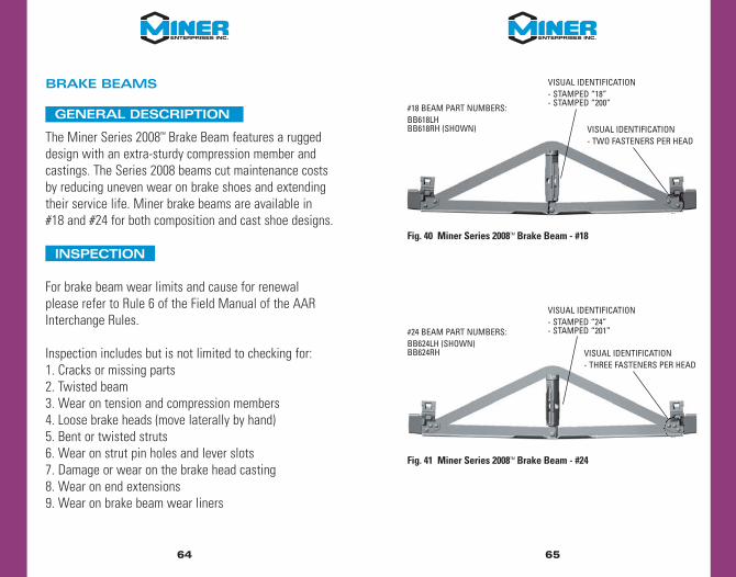
Fig. 40 Miner Series 2008™ Brake Beam - #18
Fig. 41 Miner Series 2008™ Brake Beam - #24
#18 BEAM PART NUMBERS:BB618LHBB618RH (SHOWN)
VISUAL IDENTIFICATION- STAMPED “18”- STAMPED “200”
VISUAL IDENTIFICATION- TWO FASTENERS PER HEAD
#24 BEAM PART NUMBERS:BB624LH (SHOWN)BB624RH
VISUAL IDENTIFICATION- STAMPED “24”- STAMPED “201”
VISUAL IDENTIFICATION- THREE FASTENERS PER HEAD

6766
STRUT HAND CHANGE PROCEDURE
1. Remove two-piece rivet from struta. Cut off rivet collarb. Remove rivet pin
2. Remove the struta. Tap the strut near the rivet end to rotate it sideways
until the “crown” end of the strut is free of the tension member
3. Reverse the strut to the opposite hand4. Install the strut in the beam
a. With the strut rotated approximately 30°, place the crown of the strut over the tension member
b. Hit the strut near the rivet end to rotate the strut until the holes line up
c. Rivet in place using one of the followingi. Huck: Pin LC-2R20G, Collar 3LC-2R20Gii. 5/8” grade 5 bolt and hex nut, 120-125 ft-lbs,
tack weld nut to bolt or peen bolt to prevent nut from loosening
Fig. 42 Miner Series 2008™ Brake Beam Strut Change
LEFT HAND BEAM LEVERINSERTS FROM LEFT
RIGHT HAND BEAM LEVERINSERTS FROM RIGHT