PROOF news Gerardo Ganis / CERN People working on the project:

1/25
Software Development: People, Process, Technology
Arash Khodabandeh, Paolo PalazziCERN - ECP Division - Programming Techniques Group
Abstract
The production of software is a labour intensive activity. Given the scale of software projectsrelated to current and future HEP experiments, it is worth trying to improve the knowledge ofthe PEOPLE involved, the organization of the software development PROCESS and theTECHNOLOGY used in the various aspects of this activity. The goal is better systems at lowercost and happier users of the software.
This document can be accessed through WWW at:URL = http://www.cern.ch/PTGroup/Papers/Sopron94/
The authors can be reached at:[[email protected]] and [[email protected]]
People Process Technology
Published in the proceedings of the 1994 CERN School of Computing, Sopron, Hungary.

2/25
1 IntroductionSoftware is expensive. Building it and maintaining it are labour intensive activities, but delays in deliverycan be very costly and any undetected problems may cause loss of performance and frustrate users. Thisalso applies to High Energy Physics, even though physicists have been at the forefront of computing in theearly days and, still are now in several areas.
Today the use of computers for physics is much more pervasive, and the size, complexity and lifetime ofthe software are much larger. For most of the physicists and engineers working in experiments, thebusiness is physics or engineering, not computing, and many technical managers are not computer literateenough. The use of software is growing, and often it seems that the process of producing it is out of control.There is the feeling that not enough people around have the adequate software engineering background toimprove the situation.
The software development teams around experiments are traditionally very independent. Aspects of thesoftware development culture are local to various centers, although the same application packages arewidely used in the community for some aspects of the work.
Three key components drive all improvements in software development productivity: the PEOPLEinvolved, the organization of the development PROCESS, and the TECHNOLOGY used. Talented peopleare a very important element in any software organization, but even the best professionals need anorganized environment in which to do cooperative work. The same applies to advanced technology:without an organizational framework, it cannot be fully effective, and there is evidence that going for newtechnology instead of improving the process can make things worst.
2 People
It is obvious that any software system is dependent on the quality of the people who build it. Peopleworking in Particle Physics have been selected for their intellectual abilities, so nobody could argue thatour software problems are due to the lack of talented people. Our people have produced many excellentprograms and packages, and superior programs derive from superior design.
Superior design, on the other hand, is always the work of people who understand the application domain.This is a necessary condition of success, anybody who does not understand statistics cannot build a goodstatistical system. Of course he may profit from help by those who are familiar with technical aspects ofsoftware production. We can confidently assume that in our field we have bright people, who know theirapplication domain. Let us see what they do in the scientific discovery process, and what is theirinvolvement with software.
2.1 Software for HEP
Progress in the understanding of nature is the result of the combined work of theoretical and experimentalphysicists. Theoreticians put forward new theories compatible with existing experimental results, whileexperimentalists measure new physical phenomena to disprove the theories. To measure a physicalprocess, large groups of scientists, engineers and technicians design, build and operate experiments andanalyze statistically the large amount of data produced.
The production of software is involved at all stages of the process. Scientists can be more productive in agiven domain or aspect of the data processing by using specialized systems or packages. Such softwareprovides the appropriate abstractions through a user-friendly interface. Examples of that are Mathematica

3/25
and similar systems, CAVIAR, the histogramming package HBOOK and its more recent interactive versionPAW, and so on.
2.2 Roles of people
Scientists who work close to the physics aspects of things will tend to use such specialized systems. Theseproducts will allow them to work effectively at the right level of abstraction in an easy-to-use context. Stillthere is a need to produce such programs, and this is the work of a minority of physicists. They are expertsin a given technical domain, and at the same time act as specialized developers and build systems for theothers to use. We refer to the authors of widely used scientific software, as well as to thephysicists/programmers of a collaboration. There people take responsibility for producing the dataacquisition, simulation, reconstruction and data analysis programs used by all the others.
In order to build such non-trivial software systems with a lifetime of several years or decades, specializedknowledge of software technology and a disciplined organization are both essential, and a few softwareengineering specialists need to be involved, who can advise on appropriate choices of organizationalpractices, methods and tools. Backing from the management is essential in enforcing such practices.
2.3 Open problems: specialization, training, recognition
Software for particle physics is a complex matter, where specialization is important, both in the applicationdomain, and in aspects of software engineering. The various people involved act in complementary roles,these being:
• users of the software,
• producer of the software, or
• organization, methods and tools engineers.
It is important to recognize this situation, foresee the appropriate selective training for people doingdifferent jobs, and the mechanism to acknowledge achievements and encourage mutual understanding.Teaching advanced software technology to those who do not need it may be confusing. Pretending thatsoftware is easy, so that whoever works in an experiment can stick his fingers in the code no matter how, isalso inappropriate. This will create instability in the system, frustrate the software specialists, and generateanimosity between “users” and “producers” of the software. (These considerations are controversial, andnot generally accepted in the community.) Having said that, let us concentrate on aspects of the softwareproduction process, and ways to improve it.
3 Process
Many large organizations are actively trying to find ways of producing better software at lower cost, withinpredictable resource allocations and time estimates.
In recent years, it has been realized that the way to progress is to study and improve the way software isproduced, while better technology only helps once the organizational framework is set. This disciplinegoes under the name of “Software Process Improvement” (SPI), and the reference for it is the work of theSoftware Engineering Institute [1] at Carnegie Mellon University.
The book by W. S. Humphrey, “Managing the Software Process” [2] is a good starting point to learn aboutthe basic ideas behind this approach. SPI is based on statistical process control, defined in the ‘30s and used

4/25
by Japanese industry after WW2, and by now in all industrial countries of the world. It is Total QualityManagement applied to software.
3.1 The Software Life Cycle
3.1.1 Building a house
Imagine that you just bought a nice piece of land, and would like to get a house built on it. You will live inthe house, other people will design it and build it for you. So you begin thinking about what you need:your spouse likes gardening, you have an old car and want a garage where you can work on it, you areused to age wine, enjoy to sit by the fireplace, do not like the bauhaus style etc. You also note theconstraints: shape and orientation of the land, composition of the family, size of your bookshelf, moneyavailable and so on. You write it all up on a couple of pages, and contact an architect recommended to youby reliable friends.
The architect listens to your wishes and constraints, and tries to define the properties that your ideal houseshould have. He will define number of floors and rooms, orientation of the driveway, size of the garage andso on.
When you are happy with what he proposes, he will actually design the house leaving out small details,and define its precise position and orientation. He will show you a sketch to make sure it is what you want,and produce drawings for the builders, as well as written specifications: type of bricks, colour of the wallsand so on.
Now it is time to contact a building contractor, who will actually construct the house for an agreed cost in agiven time. During the construction, details will be worked out between the architect and the builder. Aftera few months the house is ready, the architect will make sure that it corresponds to its design, ask for a fewmodifications, and soon the house is ready for you to move in.
You now live in the house with your family. You are happy, both the architect and the builder did a goodjob, without exceeding the predefined cost. There are a few minor problems with a leak in the roof and afew tiles in the balcony, but all this is readily fixed. This is not the end of the story: there will be regularmaintenance of the plumbing system, chimney, drains, painting etc., but if design was right and materialsgood and well put together, all this will not be terribly expensive nor problematic.
What really will require substantial work at a later stage has to do with the fact that your needs change. Anew baby comes, and you will have to split a large room in two, you buy a small boat and need to enlargethe garage to keep it there in the winter, and so on. The more of all this you were able to predict when youspoke to the architect, the easier and cheaper it will be to realize. Having the original plans available is alsovery helpful.
3.1.2 Life cycle
The purpose of this story was to explain by analogy how non-trivial software systems are built today. Theowner of the house had to go through several phases to get from a wish to a house he can live in. Thesecorrespond broadly to the phases of the software life cycle (figure 1), namely:
• User Requirements definition;
• Software Requirements definition;
• Architectural Design;
• Detailed Design and construction;
• Delivery to the user;
• Operations;
To consider that the life cycle phases are disjoint in time (waterfall model) is a simplification. Frequentlythe tasks of different phases are performed somewhat in parallel (concurrent engineering). It is however

5/25
important to distinguish them logically, and identify documents that are the outcome of the variousphases. For software that comes in successive version a, the life cycles of the versions usually overlap: onemay be designing version 3 while delivering version 2 to users who run version 1.
3.2 The Software Process
A process is the set of actions, tasks and procedures involved in producing a software system, throughoutits life cycle. A “good” software process must be predictable: cost estimates and schedules must be met,and the resulting product should be robust and offer the required functionality.
The objectives of software management are to produce according to plan and to improve the capability toproduce better systems. The basic principles are those of statistical process control [3], used successfully inmany fields of industry. A process is under statistical control if its future performance is predictable withinestablished statistical limits. The cornerstone of statistical process control is measurement, and measuringthe software process is not easy. One needs to define the appropriate reliable metrics, provide theinfrastructure, and consider that people are involved and may resent being “measured”.
3.2.1 Software Process Model
A typical process model covers the whole of the life cycle and clearly defines each phase and the tasks andactivities to be performed within that phase as well as those activities that are continuous throughout thelife cycle (see figure 1).

6/25
figure 1 Life cycle phases and activities.
We discussed phases already in 3.1.2, the most important activities are:
• Project management: planning, resource allocation, tracking, deadlines;
• Verification and Validation: reduce software defects and make sure that it does what the user wants;
• Software Configuration Management: handle the actual code, variants, versions and so on;
• Maintenance: fixing bugs, coping with changes at the boundary of the system, adding newfunctionality.
An example of a software process standard is ESA PSS-05 [4], defined by the European Space Agency(ESA) to fulfil its own needs to produce safety critical software. It has recently been used in HEP also, andwe will cover aspects of it in the next chapter.
3.3 Software Process Maturity
The quality of a process can be measured in terms of maturity against a recognized framework. The higherthe level of maturity the higher the quality of the organization’s process. The reference is the CapabilityMaturity Model (CMM) [5] [6] proposed by the Software Engineering Institute (SEI) [1] (see figure 2).
UserRequirements Operation
Project Management
Verification and Validation
Maintenance
Analysis andDesign Integration
DeliverySystemRequirements
ImplementationDetailed Design
Life c
ycle
Phase
s
Life c
ycle
Activit
ies
Configuration Management

7/25
figure 2 The five maturity levels of the SEI CMM.
The SEI maturity framework consists of five levels:
1 : the initial level is where most organizations begin. A level one process is usually ad hoc, fewprocesses are defined and success depends more on individual effort than team work;
2 : the repeatable level: basic project management processes are implemented to follow cost, scheduleand functionality. The process is sufficiently defined to be able to repeat earlier successes on projects withsimilar applications;
3 : the defined level: the processes for both management and engineering are documented, standardizedand integrated into a standard organizational software process
4 : the managed level requires that detailed measures are taken of the process and product, and thatprocess and product are quantitatively understood and controlled.
5 : the optimizing level: continuous process improvement is in place, using quantitative feedback.
The most difficult step is to move from level one to level two because of all the management proceduresand activities that have to be put in place. At higher levels of maturity the project management has a bettervisibility on the software process, and can take corrective actions. This visibility enables to take correctiveaction sooner when something goes wrong. The difference in maturity levels is also characterized by theability to accurately estimate and schedule product delivery and the capability of the process to meet thoseestimates. As an organization moves up the maturity levels, estimates become more accurate and the timerequired to produce a system is shorter.
3.3.1 Assessment
Before a successful attempt can be made to improve the software process, it is essential to carry out anassessment in order to rate the current status, formulate goals and an improvement program to reach thosegoals. The Bootstrap Project [7] by ESPRIT in Europe has been in operation for a few years. Starting from an
Defined(3)
Initial(1)
Repeatable(2)
Managed(4)
Optimized(5)
DisciplinedProcess
PredictableProcess
StandardConsistentProcess
ContinuousImprovementProcess
8/25
extended SEI model, an assessment procedure has been defined, and tried out on a number oforganizations in different countries. The assessment is based on two questionnaires, one addressessoftware quality attributes while the other deals with management issues that reflect the organization’smaturity. The replies are then analyzed and the results are presented showing the key attributes groupedunder three main areas: Organization, Methodology and Technology.
The weakest aspects will point in the direction of improvement actions that must be identified by theassessment team and given a priority that takes into account also external conditions such as cost, resourceavailability etc. Actions must be followed up, and the assessment/actions cycle repeated regularly, if theorganization intends to improve its maturity. A statistical survey of results from different types oforganizations and countries has shown that most of the european software producers are between levels 1and 2. Telecom companies are almost at 2, banks just above 1. National differences are also visible.
3.3.2 Is it worth improving? How?
By now the practices of SPI are well established, and have been applied in a large number of organizationsfor several years [8] [9]. The results prove unmistakably that the economical benefits are largely worth theinvestment. Spending about 1.5K ECUs per software engineer per year, can yield gains in productivitybetween 10 and 70%. Early defect detection, time to market, and quality also improve, to the point that thereturn on investment for SPI is about 500%.
Experience suggests that necessary conditions for success of an SPI effort are:
• full backing of the top management;
• implication of everybody involved;
• provision of adequate resources;
We believe SPI is worth trying also for HEP software, with an appropriate strategy that takes into accountthe peculiarities of our development environment.
4 Technology
Various activities and tasks are performed during the software development process to go from userrequirements to the delivered product. The machine can often help the human, sometimes evenautomatically, to avoid errors, work faster and concentrate the attention at the conceptual level.
The programs that help building software are called software development tools and are veryspecialized. Some are designed for one activity during the whole life cycle, while others for a specific actionlimited to one phase of the life cycle. In these notes we cannot cover all aspects of the technology concernedwith software development. We illustrate our presentation with a few tools that can help to introduce theconcepts and that we have experience with.
4.1 Technology for Life Cycle Activities
4.1.1 Project Management
Some tools are intended to support individual programmers working on specific tasks (4.2), while othershelp the management and organization of a project. Some are commercial products and one needs to payfor them, others are public domain software. ProcessWeaver (figure 3) is a process management tool thathelps to automate the development process in terms of tasks, dependency between tasks and input

9/25
and output of each task. Once the process is modelled, ProcessWeaver helps to follow its execution byautomating the start of each task within the process when all required input available. It can also start theappropriate tools needed for the execution of the task. On the other hand, MS-Project (figure 4) is a projectmanagement tool to handle resources allocated to the project in terms of manpower, time and otherresources.
figure 3 ProcessWeaver organizes the workflow of a group of developers. Each project member has an agenda (2) where eachicon represents a task he/she must perform. Clicking on an icon opens a work context (3) with a description of the task(3a), icons for all input and output documents to be produced (3b 3c) and completion/decision buttons (3d). Clicking onan input/output document will start the appropriate tool (e.g. FrameMaker, C/C++ programming environment ...).Similarly, clicking on a completion/decision button will end the task and send it to the right project member.The manager uses PetriNets (1) to model the process describing the tasks to be performed, by whom, in which orderand the input and output to each task. Each place (1a) models a task under execution by one or more project members.Each transition (1b) models the submission of a task to one or more project members after the completion of theprevious task(s). The member of the team can open a read-only dynamic view of this process model to consult its stateand see which are the tasks in progress and who is handling them.
(1)(3)
(2)
(3b)
(3d)
(3c)
(3a)
(1b)
(1a)

10/25
figure 4 The MS-Project window is divided into three sections. Section (1) is a list of tasks and sub-tasks with the start time, endtime and the resources allocated to them. Section (2) shows a time flow of all tasks with their dependencies andmilestones. Section (3) shows for each resource when it is in use, free or over allocated. Contrary to ProcessWeaver(figure 3), MS-Project only displays the information statically: it must be fed with information on the state of each task,and it reschedules all the dependent tasks automatically.
ProcessWeaver and MS-Project are complementary and can be coupled: ProcessWeaver can read the MS-Project description file to generate the process skeleton, and MS-Project can read runtime information onthe process status generated by ProcessWeaver.
(1)
(3)
(2)

11/25
Another domain where tools help is the software process assessment, to measure the maturity of theprocess and set improvement goals. The ESPRIT project, AMI (Application of Metrics in Industry),produced a 12-step method for the measurement of the software development process and starts with anSEI self assessment. It ensures that quantitative approaches are used to achieve company objectives andimprovement in the software development process. AMItool (figure 5) implements the AMI method andtakes the user from the SEI questionnaire to the measurement plan.
figure 5 AMItool implements the AMI method. To begin with one answers an SEI questionnaire (1). AMItool compiles andpresents the results of the questionnaire in a Kiviat graph (2). On this Kiviat graph each axis represents one domain ofthe process (e.g. Training, Organization) and is divided into the 5 SEI CMM levels. A dot is placed at the correspondinglevel of maturity on each axis. The process manager, using the results of the questionnaire, identifies primary goals(e.g. ‘Gain Better Understanding of Project Costing’) and decomposes them, in the goal tree (3), down to basic sub-goals. He then defines metrics and interpretation rules and associates them to goals and basic sub-goals (4). AMItoolthen generates a plan (5) for the measurement of the process. After a while, another AMI iteration can start.
(5)
(1)
(2)
(3)
(4)

12/25
Communication and information flow in a project can be improved by suitable tools. For example, adiscussion involving more than two people over the network, can be difficult to follow because more thanone idea is discussed at the same time. This is where WIT (World Wide Web Interactive Talk) [11] can help.WIT (figure 6) allows discussions through the WWW and displays discussion items in a structured fashion.Lotus Notes is a commercially available tool addressing the same problem, that works across UNIXmachines PCs and Macs.
figure 6 A WIT system is composed of Discussion Areas. A Discussion Area is a general subject, which has specific aspects,called Topics (1), and each Topic is composed of Proposals (2) which generate an exchange of messages (3). The bigadvantage of WIT over the news groups is the structuring. When looking at a Proposal one can see what has beendiscussed, who answered to whom, who agrees/disagrees with whom, etc. WIT is not only useful to browse throughdiscussions but it is also possible to agree ( ) or disagree ( ) with any statement in the Proposal using the tool itself.
(3)
(2)
(1)

13/25
At each stage of the life cycle many documents are produced by different people: requirementsspecification, analysis, source code, user manuals, etc. These documents are heavily structured and cross-referenced. LIGHT (LIfecycle Global HyperText) [12] integrates these documents and allows to navigate(figure 7) between and inside requirements, diagrams, code, manuals, etc.
figure 7 The LIGHT concept is illustrated by this ADAMO [13] example. The navigation map (1) shows all documents that arelinked here: pictures, requirements, analysis diagrams (2), DDL (3), FORTRAN source code (4) and ADAMO referencemanuals (5). Clicking on any of the document symbols will go to the corresponding document, which is itself linked tothe others. For example clicking on the “track” class in the diagram will open the “track” declaration in the DDL. Similarlyclicking on an ADAMO routine call within the code will open the ADAMO manual entry for that routine.
4.1.2 Verification and Validation
PSS-05 defines the two sub-activities in the Software Verification and Validation (SVV) activity [4] [14] asfollows:
“Verification is the act of reviewing, inspecting, testing, checking, auditing, or otherwise establishing anddocumenting whether or not items, processes, services or documents conform to specified requirements(ANSI/ASQC A3-1978).
Validation is, according to its ANSI/IEEE definition, ‘the evaluation of software at the end of the softwaredevelopment process to ensure compliance with the user requirements’. Validation is, therefore, ‘end-to-end’ verification.”
(1)
(4)
(2)
(3)
(5)

14/25
The Verification software must itself be specified and written. Many commercial tools are available to helporganize verification and validation activities. For example, Purify and TestCenter (figure 8) detect memoryaccess errors and memory leaks in C and C++ programs. Similarly, TestCenter and Logiscope (figure 9) canvisualize which part of the code has been executed during tests (test coverage). Programming in a higherlevel language is another way of preventing this class of programming errors.
figure 8 TestCenter is an environment for C/C++ testing and debugging. It shows memory leaks (memory with no pointer to it)and possible memory leaks (memory with a pointer to its middle). It can also detect runtime errors such as: pointer andarray boundary errors, use of uninitialized memory, attempted write to read-only memory, errors using free andunanticipated termination signals. For both the memory leaks and runtime errors, TestCenter gives respectively in theleak browser (1) and the error browser (2) information on the problem. It also shows the source code line where theerror was introduced, and can help with test coverage analysis to some extent.
figure 9 Logiscope performs test coverage analysis for programs. It displays the call graph tree (1) and highlights the functioncalls not executed; similarly for each function, it shows the control graph (2) and highlights the instruction blocks notexecuted.
(2)(1)
(1)
(2)

15/25
The verification and validation will introduce changes and new releases of the software. It is important tobe able to perform defect logging and tracking with a flexible source code manager with a database and aquery system.
4.1.3 Configuration Management
The elements subject to configuration management are: source code, internal documentation of all sorts(requirements, etc.), manuals, tools, test software and test results. The software configuration managementincludes many tasks such as: 1- controlling the release and changes of each element 2- logging andanalyzing changes and reasons for each of them.
As mentioned in 4.1.2 a source code manager based on some kind of a database can help control whochanges what, why and when (librarian checkin/checkout). It must also log all the changes, providestatistics and/or process queries.
The last configuration management task consists of verifying the completeness and correctness of singlemodules. For example, one must check the style and do statistical measurements to make sure that the codefollows agreed criteria. This work can be done with specialized tools, possibly integrated in the source codemanager. Logiscope that we saw as a test coverage tool in figure 9 can compute software metrics forvarious programming languages and display the results graphically (figure 10).
figure 10 For each function Logiscope calculates a set of metrics (size, comment rate, cyclomatic number, etc.) and displays theresults in a Kiviat graph (1). Each axis is one metric. The plot is the value of that metric for this function. The two circlesrepresent the minimum and maximum values acceptable. The metric distribution graph (2) is the detail of one metric(here the cyclomatic number, and indicator of local code complexity, high for “spaghetti” code). Clicking on a bar of thehistogram will display the list of the functions for which the metric has the corresponding value. The configurationmanager can consult the control graph of each function. Logiscope also measures and displays metrics on the callgraph (reachability of a function, testability of a function, etc.). It can also check programming rules (banned keywords,consistent usage of case, misusage of brackets, etc.). These rules and reference values for the metrics are defined bythe quality manager, and problems pointed out by Logiscope can be analyzed by the quality manager or by theprogrammer himself.
4.1.4 Maintenance
Once the software is developed, tested and delivered, users will start to work with it, and suggestions andbug reports will come in. The maintenance team will sort this input and set priorities. After improving the
(1)
(2)
16/25
software the development team carries out regression tests (i.e. old tests still work and no new bugs areintroduced). They may also have to introduce new test programs for the newly detected bug.
4.2 Technology for Life Cycle Phases
In the early phases of the life cycle, user requirements must be expressed in detail. This is usually donewith structured text in a natural language, and some kind of referencing scheme. A good text processingsystem with templates and cross referencing can be very useful, but specialized requirements tools arebeginning to appear.
4.2.1 User Requirements
This is how ESA PSS-05 [4] [15] defines the User Requirement (UR) phase:
“The UR phase is the ‘problem definition phase’ of a software project. The scope of the system must bedefined. The user requirements must be captured. This may be done by interview or survey, or by buildingprototypes. Specific user requirements must be identified and documented in the User RequirementsDocument (URD).
The involvement of the developers in this phase varies according to the familiarity of the users withsoftware. Some users can produce a high quality URD, while others may need help from the developers.
The URD must always be produced. The review of the URD is done by the users, the software andhardware engineers and the managers concerned.”
As an example of URD, one can have a look at WebMaker [16] and WebLinker [17] where PSS-05 was usedfor expressing the User Requirements.
4.2.2 System Requirements
ESA PSS-05 [4] [18] defines the System Requirement (SR) as:
“The SR phase is the ‘analysis’ phase of a software project. A vital part of the analysis activity is theconstruction of a ‘model’ describing ‘what’ the software has to do, and not ‘how’ to do it. Buildingprototypes to clarify the software requirements may be necessary.
The principal deliverable of this phase is the Software Requirements Document (SRD). An SRD mustalways be produced for every software project. Implementation terminology should be omitted from theSRD.”
The WebLinker System Requirements [19] have been written using the PSS-05 standards. They contain thetraceability matrix that proves the SRD's completeness: System Requirements cover all User Requirementsand nothing more.
To formulate the User and System Requirements according to a given framework, one may use specializedtools such as DOORS. These tools check the consistency between Requirements and automaticallymaintain traceability information. The Requirements mentioned above and in 4.2.1 have been writtenusing simple templates for a text processor and automatically translated to WWW [20].
4.2.3 High-Level Design
During this phase (called Architectural Design in PSS-05 [4] [21]) the overall structure of the system isspecified: the software construction begins. There are several methods, more or less object-oriented, thatcan be used in this activity such as SASD/TR [22] [23], PROTOB (PetriNets with objects) [24] [25], ClassRelation[26], Martin/Odell [27], OMT [28], FUSION [29] to name just a few. They all have different modelsto represent different aspects of the system. For example OMT and Class Relation put the emphasis on theobject model, while PROTOB has a stronger dynamic model and SASD focuses first on the functionalmodel. The choice of a method is driven by the characteristics of the system under development,knowledge of the team and so on.

17/25
A CASE tool can help in the application of the method. For example, Artifex (figure 11) supports thePROTOB method based on High Level Colored Concurrent PetriNets with simulation and C/ADA codegeneration. Similarly, Objecteering (figure 12) implements the Class Relation method with C++ codegeneration. For a given method one finds usually many tools to supports it and needs to choose theappropriate one. IEEE has produced recommendations for the evaluation and selection of CASE Tools [30]and suggests criteria such as: how well the methodology is supported, are all the concepts covered, howmuch consistency checking is performed, how much the tool can be customized and the quality of itsgraphical user interface.
figure 11 Artifex checks that the PetriNets are consistent and complete. It also allows debugging and prototyping with itsinteractive simulation tool. Artifex generates distributed code along with the Makefiles. Developers can even compile,start the remote code and monitor the execution using the interface. The logic of the PetriNet and the inter-processcommunications are all handled by the tool. Developers can concentrate on the model and specification of the actionsin a transition.
18/25
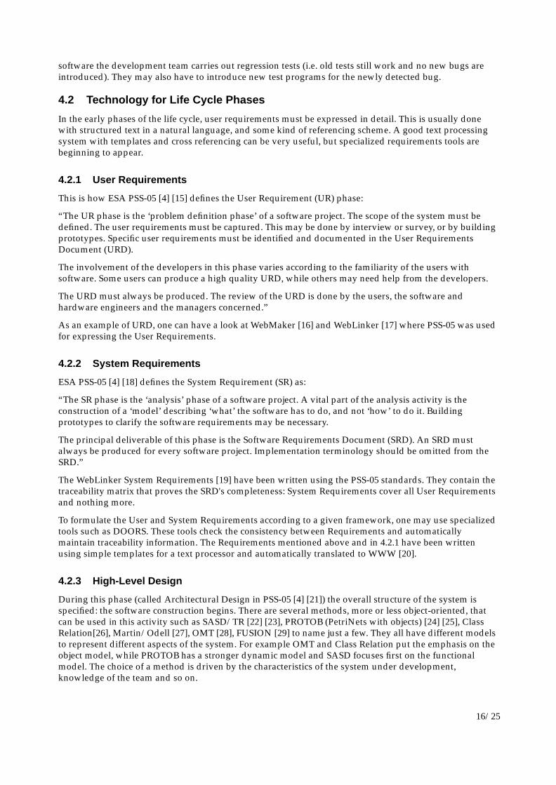
figure 12 With Objecteering, the developer performs the analysis using the CR notation (1). He can enter the methodspecification in C++ through the graphical user interface (2). Objecteering can then generate the C++ code andautomatically integrate the user specified part in the right place (3). All the syntax of the C++ files, the test statements(IFDEFs) and the relationship operators are automatically generated and taken care of by the tool. Developers canconcentrate on the method and the model specification.
4.2.4 Detailed Design and Coding
This phase (called Detailed Design and Production in PSS-05 [4] [31]) uses as input the High-Level Designphase output and produces the software. This code is then unit tested, integration tested and system tested.
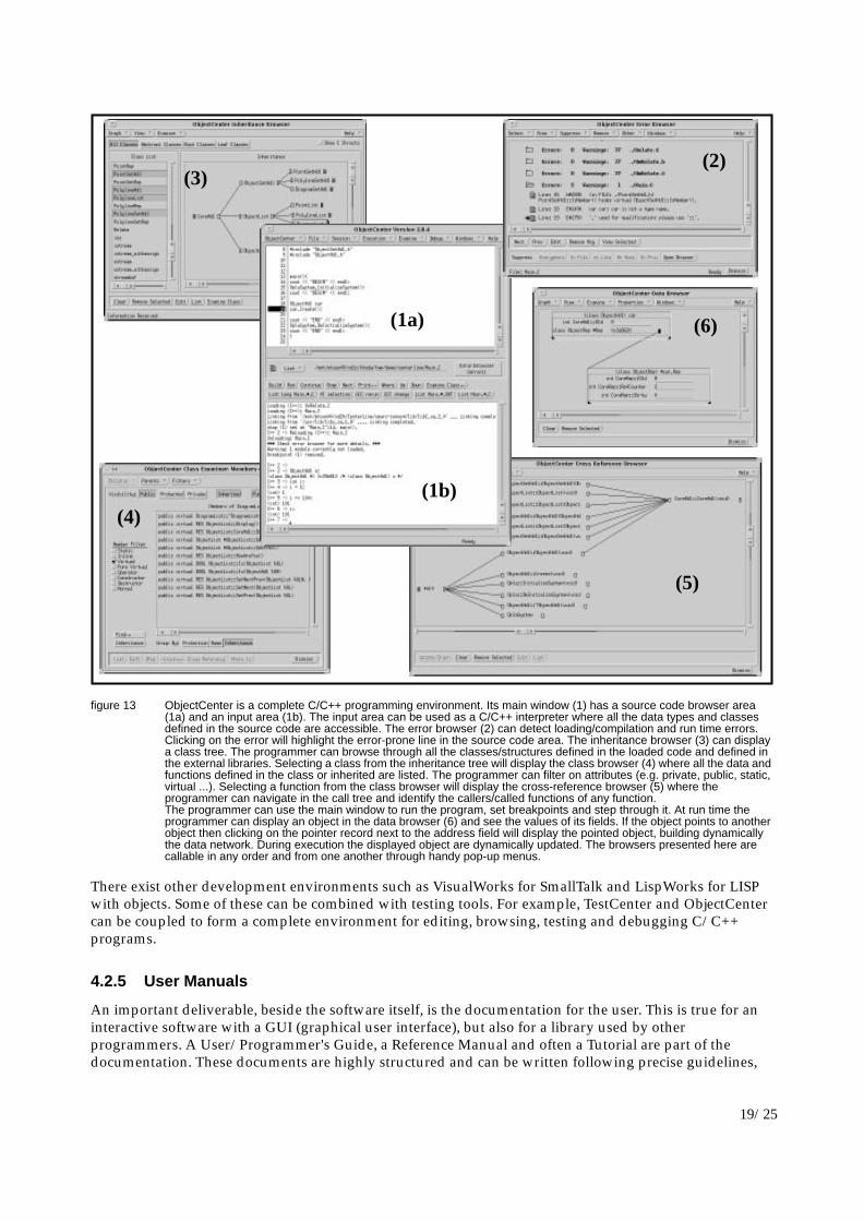
The choice of the CASE tool to support the activities of this phase is driven mostly by the language usedand the detailed required functionality. A programming environment with a class/inheritance browser isuseful for Object-Oriented languages. For example, ObjectCenter (figure 13) is a complete C/C++programming environment with a debugger, an interpreter and class/function/data browsers. One mayalso employ a testing tool that can detect memory leaks if dynamic memory is used (see 4.1.2 figure 8).
(3)
(2)
(1)
19/25
figure 13 ObjectCenter is a complete C/C++ programming environment. Its main window (1) has a source code browser area(1a) and an input area (1b). The input area can be used as a C/C++ interpreter where all the data types and classesdefined in the source code are accessible. The error browser (2) can detect loading/compilation and run time errors.Clicking on the error will highlight the error-prone line in the source code area. The inheritance browser (3) can displaya class tree. The programmer can browse through all the classes/structures defined in the loaded code and defined inthe external libraries. Selecting a class from the inheritance tree will display the class browser (4) where all the data andfunctions defined in the class or inherited are listed. The programmer can filter on attributes (e.g. private, public, static,virtual ...). Selecting a function from the class browser will display the cross-reference browser (5) where theprogrammer can navigate in the call tree and identify the callers/called functions of any function.The programmer can use the main window to run the program, set breakpoints and step through it. At run time theprogrammer can display an object in the data browser (6) and see the values of its fields. If the object points to anotherobject then clicking on the pointer record next to the address field will display the pointed object, building dynamicallythe data network. During execution the displayed object are dynamically updated. The browsers presented here arecallable in any order and from one another through handy pop-up menus.
There exist other development environments such as VisualWorks for SmallTalk and LispWorks for LISPwith objects. Some of these can be combined with testing tools. For example, TestCenter and ObjectCentercan be coupled to form a complete environment for editing, browsing, testing and debugging C/C++programs.
4.2.5 User Manuals
An important deliverable, beside the software itself, is the documentation for the user. This is true for aninteractive software with a GUI (graphical user interface), but also for a library used by otherprogrammers. A User/Programmer's Guide, a Reference Manual and often a Tutorial are part of thedocumentation. These documents are highly structured and can be written following precise guidelines,
(1a)
(2)(3)
(4)
(5)
(6)
(1b)

20/25
such as STOP [32]. They usually include a table of contents, a map of the document, a glossary, an indexand a bibliography. Graphics is a must to make the document easier to understand and more readable.
Often the same information can have many incarnations that must be kept coherent. For example aReference Guide that exists on paper can also be published electronically on the World-Wide Web [20] andbe integrated in the on-line help.The paper “An Automated System for the Maintenance of MultiformDocuments” [33] (figure 14) shows how this was achieved for one specific product.
figure 14 As an example, the paper “An Automated System for the Maintenance of Multiform Documents,” shows how theADAMO documentation is automatically maintained on paper, World-Wide Web and KUIP. The system usesFrameMaker (1) as the master format and to produce the printed version. Automatic converters generates HTML forWWW (2) and CDF for KUIP (3). Examples are dynamically compiled, run and included, to ensure that they are inlinewith new features.
4.2.6 Integration
The integration phase is where all the pieces of the system are put together. These may consist of differentexecutables, libraries, include files, documentation (see 4.2.5) and the installation scripts. The integration isa detailed process where deliverables must be put in the right place and tested. The failure of any test leadsto further development followed by another integration phase. This means that one may need to gothrough the integration process many times and follow the same steps each time. This is a typical examplewhere a tool such as ProcessWeaver can help in automating the repeatable part of the process. Asmentioned in 4.1.1 figure 3, ProcessWeaver is a management tool that helps to automatize the process(figure 15) in terms of tasks, dependency between tasks and input and outputs of each task.
(1)(2)
(3)

21/25
figure 15 Like Artifex (see 4.2.3) ProcessWeaver uses PetriNets for modelling. The above model is the “WebMaker TAR fileverification process model.” The “TE_TAR_Collect_TS_TAR_Creation” is activated when a previous process (notshown) leads to the collection of all deliverables. Then the TAR file is created. With the transition“TE_TAR_Creation_TS_TAR_Review” all testers concerned are asked to test and accept/refuse it. Depending on thenumber of refusals “CollectAnswer” will either go back to produce a new tar file with “TAR_Review_Incomplete” andrestart the process or continue with “TAR_Review_Complete_TS_TAR_MAIL” to mail the announcement of the newversion to the user. The actions performed in each transition (creation of the TAR, test of the TAR, delivery of the mail)are not modelled as part of the process, but ProcessWeaver can call external tools. For example it can call a shell scriptfor the creation of the TAR or to run tests and analyze the output.
4.2.7 Delivery
Once the TAR file of deliverables is ready the delivery can start. It may consist of several steps (figure 16):inform the user of the availability of the software, distribute it, provide installation instructions and finallyrun the installation scripts. Nothing magic, but a non negligible amount of work.

22/25
figure 16 The files above are from WebMaker, a current development of the CERN ECP Programming Techniques Group. Theavailability of the software is announced to the users registered on a mailing list via a Bulletin (1). The user may ask toretrieve the software by ftp and is given instructions by E-mail (2). In the delivery kit, README files (3) explain thecontents of each file/directory and lead the user through the installation process. A large part of the installation is donewith shell scripts (4).
4.2.8 User Support
Part of user support is information. The goal is to allow users to work without assistance by providingthem with all the necessary information that is constantly kept up to date. The World-Wide Web is ideal forthis task (figure 17): the information is easily accessible, it can be linked to other documents and users get
(1) (2)
(3) (4)

23/25
always the latest versions. Some of the WWW information can be derived from the printed version (4.2.5figure 14).
figure 17 This is the WebMaker information Web. From the entry page (1) WebMaker users can consult the User’s Manual (2)(generated as explained in 4.2.5), the Frequently Asked Questions (3), interesting examples, list of bugs andsuggestions to name but a few.
Documentation and public information will never be perfect and usually many user’s queries will need tobe handled preferably via electronic mail. A system such as MH-mail (figure 18), a highly configurable mailhandler, can be of great help by filing messages automatically.
(1)(2)(3)

24/25
figure 18 MH-mail and its X interface EXMH can file the mail in a separate folder (2), reply to the mail, register the sender in amailing list etc. All this according to rules specified in a configuration file and depending on the subject, sender or anyheader information in the mail. It also acts as a standard mail tool with a GUI (1) to read messages, and reply manuallyto them.
Acknowledgments
We would like to thank Ian Hannell for contribution and advice concerning the process part and help withthis document, Pierrick Pinasseau for setting up the cluster we used in Sopron and for his daily assistanceduring the school, Joel Closier for the installations of all the software tools used, and the suppliers of thetools who kindly provided us with free demonstration licences and information leaflets for those howattended the lectures.
References
[1] Software Engineering Institute (SEI), http://www.sei.cmu.edu/FrontDoor.html
[2] Managing the Software Process, W. S. Humphrey, Addison-Wesley, 1990
[3] Quality, productivity and Competitive Position, W.E. Deming, MIT 1982
[4] ESA Software Engineering Standards, PSS-05-0 Issue 2, February 1991. European Space Agency, 8-10,rue Mario-Nikis, F-75738 Paris Cedex.
[5] Capability Maturity Model for Software, V1.1. (CMU/SEI-93-TR-24), Software Engineering Institute,1993
[6] Key Practices of the Capability Maturity Model, V1.1. (CMU/SEI-93-TR-25), Software EngineeringInstitute, 1993
[7] Process Assessment: The BOOTSTRAP Approach, G.R. Koch, ESPRIT, 1993,http://www.cern.ch/PTGroup/spi/process_ass/bootstrap.html
[8] Benefits of CMM-Based Software Process Improvement: Initial results (CMU/SEI-94-TR-13) J.Herbsleb, A. Carleton, J. Rozum J. Siegel, D. Zubrow, Software Engineering Institute, 1994
(1) (2)

25/25
[9] Software Improvements at an International Company, H. Wohlwend and S. RosenbaumSchlumberger Laboratory for Computer Science, Austin, Texas, USA
[10] Carnegie Mellon University, http://www.cmu.edu
[11] W3 Interactive Talk (WIT), http://info.cern.ch/hypertext/WWW/WIT/User/Overview.html
[12] LIfecycle Global HyperText (LIGHT), http://www.cern.ch/Light/
[13] ADAMO, an Entity-Relationship Programming System, CERN, ECP Division, ProgrammingTechniques group, http://www.cern.ch/Adamo/ADAMO_ENTRY.html
[14] Guide to Software Verification and Validation, PSS-05-10 Issue 1, February 1994. European SpaceAgency, 8-10, rue Mario-Nikis, F-75738 Paris Cedex.
[15] Guide to the User Requirements Definition Phase, PSS-05-02 Issue 1, October 1991. European SpaceAgency, 8-10, rue Mario-Nikis, F-75738 Paris Cedex
[16] WebMaker User Requirements, http://www.cern.ch/WebMaker/UserReq/Document.html
[17] WebLinker User Requirements, http://www.cern.ch/WebLinker/WebLinker_8.html#HEADING7
[18] Guide to the Software Requirements Definition Phase, PSS-05-03 Issue 1, October 1991. EuropeanSpace Agency, 8-10, rue Mario-Nikis, F-75738 Paris Cedex.
[19] WebLinker System Requirements,http://www.cern.ch/WebLinker/WebLinker_21.html#HEADING20
[20] World-Wide Web Initiative, http://info.cern.ch/hypertext/WWW/TheProject.html
[21] Guide to the Software Architectural Definition Phase, PSS-05-04 Issue 1, January1992. EuropeanSpace Agency, 8-10, rue Mario-Nikis, F-75738 Paris Cedex.
[22] Strategies for Real-Time System Specification, Derek J. Hatley, Imtiaz A. Pirbhai. Dorset HousePublishing, 1987, New York, N.Y. ISBN 0-932633-11-0
[23] Structured Development for Real Time Systems, Paul T. Ward, Stephen J. Mellor. Prentice-Hall, 1985,Englewood Cliffs, N.J.
[24] ARTIS, The Artifex Environment USER GUIDE, ARTIS, Torino, Italy, July 17th, 1991.
[25] ARTIS, AXEN-C-SCR-MAN-E-V2.3. Artifex C Script REFERENCE MANUAL, ARTIS, Torino, Italy,July 17th, 1991.
[26] Object Engineering, The Fourth Dimension, Philippe Desfray, Addison Wesley, 1994, Paris. ISBN 0-201-42288-3
[27] Object-Oriented Analysis and Design, James Martin, James J. Odell, Prentice-Hall, 1992, EnglewoodCliffs, N.J. ISBN 0-13-630245-9
[28] Object-Oriented Modeling and Design, James Rumbaugh et al., Prentice-Hall, 1991, EnglewoodCliffs, N.J. ISBN 0-13-629841-9
[29] Object-Oriented Development, The Fusion Method, Derek Coleman et al., Prentice-Hall, 1994,Englewood Cliffs, N.J. ISBN 0-13-101040-9
[30] IEEE Recommended Practice for the Evaluation and Selection of CASE Tools, IEEE 345 East 47thStreet, New York, NY 10017-2394, USA, IEEE Std 1209-1992, ISBN 1-55937-278-8
[31] Guide to the Software Detailed Design and Production Phase, PSS-05-05 Issue 1, May 1992. EuropeanSpace Agency, 8-10, rue Mario-Nikis, F-75738 Paris Cedex.
[32] Everything You Ever Wanted to Know about Documentation (and Should Have Asked), C. Fidge, D.Heagerty, Telecom Australia, 1986
[33] An Automated System for the Maintenance of Multiform Documents, B. Rousseau, M. Ruggier, M.Smith, CERN/ECP Report 94-14,http://www.cern.ch/WebMaker/examples/CHEP94_adamodoc_2/www/adamodoc_1.html