Pentium III Processor Active Thermal Management...
48
Pentium ® III Processor Active Thermal Management Techniques Application Note August 2000 Order Number: 273405-001
Transcript of Pentium III Processor Active Thermal Management...

Pentium® III Processor Active Thermal Management TechniquesApplication Note
August 2000
Order Number: 273405-001

Application Note
Information in this document is provided in connection with Intel® products. No license, express or implied, by estoppel or otherwise, to any intellectual property rights is granted by this document. Except as provided in Intel’s Terms and Conditions of Sale for such products, Intel assumes no liability whatsoever, and Intel disclaims any express or implied warranty, relating to sale and/or use of Intel products including liability or warranties relating to fitness for a particular purpose, merchantability, or infringement of any patent, copyright or other intellectual property right. Intel products are not intended for use in medical, life saving, or life sustaining applications.
Intel may make changes to specifications and product descriptions at any time, without notice.
Designers must not rely on the absence or characteristics of any features or instructions marked “reserved” or “undefined.” Intel reserves these for future definition and shall have no responsibility whatsoever for conflicts or incompatibilities arising from future changes to them.
The Pentium® III processor may contain design defects or errors known as errata which may cause the product to deviate from published specifications. Contact your local Intel sales office or your distributor to obtain the latest specifications and before placin g your product order.
Copies of documents which have an ordering number and are referenced in this document, or other Intel literature may be obtained by calling 1-800-548-4725 or by visiting Intel’s website at http://www.intel.com.
Copyright © Intel Corporation, 2000
*Third-party brands and names are the property of their respective owners.

Contents
Contents1.0 Overview ........................................................................................................................5
2.0 Measuring the Processor Temperature ............................................................5
3.0 Lowering the Temperature of the Processor ..................................................6
3.1 Clock Throttling Implementation with Microcontroller............................................93.2 Reference Example.............................................................................................103.3 Reference Source Code......................................................................................103.4 Test Results ........................................................................................................12
3.4.1 Case 1: Fan and Heatsink Installed, Windows* 98 Running ..............133.4.2 Case 2: Fan and Heatsink Installed, Windows 98
and Thermal Stress Software Running ..............................................153.4.3 Case 3: Fan and Heatsink Removed, Windows* 98 Running ............163.4.4 Case 4: Fan and Heatsink Removed, Windows* 98
and Thermal Stress Software Running, Worst Case..........................18
4.0 Customizing the Source Code ............................................................................19
5.0 Summary......................................................................................................................20
A Software Listings .....................................................................................................21
Figures
1 Using the MAX1617A to Measure Temperature ...................................................62 Stop Clock State Machine .....................................................................................73 Using the PIIX4E for Throttling..............................................................................84 Using an 8-bit Microcontroller to Manage Temperature ........................................95 Alternative Method Using an 8-bit Microcontroller with Integrated A/D and
Analog Front-end.................................................................................................106 Flowchart of Clock Throttling Software Program.................................................127 Performance vs. Time, 700 MHz Pentium® III Processor,
FCPGA, Fan On, No Thermal Stress Software...................................................138 TJunction vs. Time, 700 MHz Pentium® III Processor,
Fan On, No Thermal Stress Software .................................................................149 Performance vs. Time, 700 MHz Pentium® III Processor,
FCPGA, Fan On, Thermal Stress Software Running ..........................................1510 TJunction vs. Time, 700 MHz Pentium® III Processor,
FCPGA, Fan On, Thermal Stress Software Running ..........................................1611 Performance vs. Time, No Fan, No Heatsink,
700 MHz Pentium® III Processor, FCPGA, No Thermal Stress Software ...........1712 TJunction vs. Time, 700 MHz Pentium® III Processor, FCPGA,
No Fan, No Heatsink, No Thermal Stress Software............................................1713 Performance vs. Time, 700 MHz Pentium® III Processor,
FCPGA, No Fan, No Heatsink, Thermal Stress Software Running.....................1814 TJunction vs. Time, 700 MHz Pentium® III Processor, FCPGA,
No Fan, No Heatsink, Thermal Stress Software Running ...................................19
Application Note 3

Contents
Tables
1 Clock Throttle Constants..................................................................................... 192 File Types and Purpose for Clock Throttling Program ........................................ 20
4 Application Note

Pentium® III Processor Active Thermal Management Techniques
1.0 Overview
The maximum power consumption of Pentium® III processors can range from 12.2 W to more than 26 W. Embedded processors may easily reach their maximum specified die temperature during high load situations and when they are subjected to high ambient temperatures. For this reason, system designers should consider implementing an active thermal management solution to ensure that the processor die temperature is within specification.
This application note presents various methods of throttling the Pentium III processor to ensure that the processor remains within its temperature specification. This document also includes the following:
• Techniques on how to monitor and control the processor temperature in embedded systems.
• Instructions on how to access the various temperature sensors and power management features of a Pentium III processor chipset.
• A reference example of clock throttling using a microcontroller.
2.0 Measuring the Processor Temperature
A key part of active thermal management is to accurately measure the processor temperature. The temperature on a Pentium III processor can be accurately measured using the centrally located on-die thermal diode. The diode provides a method of measuring the temperature to ensure that the processor is within its tested specified operating temperature range. The anode and cathode of the on-die temperature diode can be interfaced to a thermal sensor component via two pins of the processor. The temperature of the diode can be computed from the following equation:
Where:
ID = Current through diodeIS = Reverse Saturation CurrentVD = Voltage drop across dioden = Diode Ideality Factor (always >1) (1.0057 to 1.0125)T = Temperature of diodeq = Constant
This equation can be simplified to the following:
ID IS eK
1–( )= KqVD
nT----------=; where
TqVD
nID
IS----- 1+
ln
-----------------------------=
Application Note 5

Pentium® III Processor Active Thermal Management Techniques
ssor’s
Many thermal sensors are available that can be directly connected to the thermal diode on the processor, including the Maxim MAX1617A*, Analog Devices: ADM1021, ADM1022, ADM9240 or National Semiconductor LM84. An example using the MAX1617A to measure the temperature is illustrated in Figure 1. uctio
The thermal sensor can be used to report the die and ambient temperatures. These sensors can be interfaced to the Pentium III processor or a thermal microcontroller using various buses. The most common bus is the SMBus, which is a derivation of the I2C* bus. The sensor can report the temperature at regular intervals over the SMBus, by polling from the Pentium III processor, or by generating an ALERT# if the temperature crosses a set trip point.
3.0 Lowering the Temperature of the Processor
Once the thermal sensor has detected that the processor temperature is out of the specified operating range, it is up to the microcontroller or chipset to begin throttling the processor into a lower power state. Another method to reduce the processor temperature is to have the microcontroller turn on a fan. Throttling the processor is accomplished by toggling the STPCLK# pin on the processor. When the STPCLK# pin is pulled low, the processor initiates a bus request and waits until it obtains ownership of the bus. After it obtains ownership of the bus, the processor places itself in the Stop Grant state which consumes less power (see Figure 2). In the Stop Grant state, clocks are stopped to the various logic blocks within the processor, except for the procePLL. To exit from the Stop Grant state, deassert STPCLK#. Only 10 internal bus clocks are required to exit.
Figure 1. Using the MAX1617A to Measure Temperature
A8080-01
C1030.1µF
C1020.1µF
R2810K
R2910K
R3010K
THERMDP
2
3
4
15
1412
SM_CLKSM_DATA
1591316
11
10
6
78
THERMDN
R321K
R331K
R31270
X
VCC
DXP
DXN
STBY#
SMBDATASMBCLKALERT#
ADD0
ADD1
GNDGND
MAX1617A
V3_3
Notes: 1. Routing Guidelines: Route THERMDP and THERMDN as a differential pair.2. Address Select straps current address: 1001 110
V3_3
V3_3
XN/C
XN/C
XN/C
XN/C
XN/C
6 Application Note

Pentium® III Processor Active Thermal Management Techniques
Note: To ensure that the Pentium III processor enters the Stop Grant state when STPCLK# is asserted, the processor must not be in QuickStart Mode. Please see the Pentium® III Processor for the PGA370 Socket at 500 MHz to 1.0B GHz datasheet (order number 245264) for more information on how to enter the Stop Grant state and on the limitations of QuickStart.
Figure 2. Stop Clock State Machine
A8101-01
HALT Instruction andHALT Bus Cycle Generated
STPCLK# Asserted
STPCLK# De-asserted andStop-Grant State Entered from AutoHALT
1. Normal StateNormal Execution.
2. Auto HALT Powerdown StateBCLK Running.Snoops and Interrupts Allowed.
INIT#, BINIT#, INTR,SMI#, RESET#
Snoop Event Occurs
Sno
op E
vent
Occ
urs
3. Stop Grant StateBCLK Running.Snoops and Interrupts Allowed.
4. HALT/Grant Snoop StateBCLK Running.Service Snoops to Caches. Snoop Event Serviced
Sno
op E
vent
Ser
vice
d
ST
PC
LK#
Ass
erte
d
ST
PC
LK#
De-
asse
rted
5. Sleep StateBCLK Running.No Snoops or Interrupts Allowed.
SLP
#A
sser
ted
SLP
#D
e-as
sert
ed
6. Deep Sleep StateBCLK Stopped.No Snoops or Interrupts Allowed.
BC
LK In
put
Sto
pped
BC
LK In
put
Res
tart
ed
Application Note 7

Pentium® III Processor Active Thermal Management Techniques
ling, 2.5%
PEN
ting
n this te duty s. This is
The simplest implementation to control the temperature of the processor can be constructed using the temperature sensor and the PIIX4E southbridge to throttle the processor. The PIIX4E contains necessary logic to throttle the processor with a minimum amount of software. This example is illustrated in Figure 3.
In this implementation, the processor programs the MAX1617A to generate the ALERT# signal (connected to THRM# on the PIIX4E) when the temperature approaches a critical zone. When the THRM# pin on the PIIX4E is held low for more than two seconds, the PIIX4E begins throttling the STPCLK# pin with the programmed duty cycle and with a period of 244 µS. To enable throttthe THT_EN bit of the PCNTRL register must be set. The duty cycle can be programmed in 1increments in the THRL_DTY field of the Processor Control Register (PCNTRL BASE+(10-13H)). To have the THRM# signal generate an SMI or SCI event, the THRM_EN bit of the Gregister must be set. Refer to the 82371AB PCI-to-ISA/IDE Xcelerator (PIIX4) datasheet (order number 290562) for more detailed information.
However, if the duty cycle of STPCLK# is not sufficient to cool down the processor, the operasystem or System Management software must reprogram the duty cycle to slow down the processor. This may involve inserting interrupt routines.
Another method to manage the temperature of the processor uses an 8-bit microcontroller. Iimplementation, the microcontroller polls the temperature sensor and generates an appropriacycle for STPCLK#. The duty cycle on STPCLK# can decrease as the temperature increaseensures that the least amount of performance is sacrificed as the temperature increases. Thimplementation is illustrated in Figure 4. An advantage of this method is that it can be accomplished completely in hardware, without software interventions on the Pentium III processor or chipset.
Figure 3. Using the PIIX4E for Throttling
A8082-01
Intel® Pentium® lllProcessor
Intel® 82443BXHost Bridge/Controller
82371EBPCI-to-ISA/IDE
Xcelerator(PllX4E)
MAX1617A
SMBus
THRM#
STPCLK#
THERMDN
THERMDP
ALE
RT
8 Application Note

Pentium® III Processor Active Thermal Management Techniques
—the to
ion
-end is n this is
3.1 Clock Throttling Implementation with Microcontroller
A reference example of clock throttling is provided in this application note. The assembly code is included in Appendix A. There are several ways of implementing clock throttling using a microcontroller. One way is to use a temperature sensor such as the one provided by MaximMAX1617A. This sensor uses the SMBus to communicate the temperature information and receive setup information.
An 8-bit microcontroller interfaces easily using the SMBus, and based upon the temperatureinformation, performs the clock throttling function. This is the method detailed in this applicatnote (see Figure 4).
Another possible method reduces cost by removing the temperature sensor. An analog frontneeded to provide a constant current source to the thermal diode and amplify to the signal. Icase, the thermal diode can be linearized in software or with a filter. This alternative methodshown in Figure 5.
Figure 4. Using an 8-bit Microcontroller to Manage Temperature
A8083-01
Intel® Pentium® lllProcessor
Intel® 82443BXHost Bridge/Controller
82371EBPCI-to-ISA/IDE
Xcelerator(PllX4E)
MAX1617A
STPCLK#
SM
Bus
THERMDP
THERMDN
Microcontroller
Application Note 9

Pentium® III Processor Active Thermal Management Techniques
3.2 Reference Example
To demonstrate clock throttling with an Intel 700 MHz Pentium III processor, the following tools/components were used:
• Microchip PIC16F876 8-bit microcontroller (A/D, USART, 28 pins, I2C)
• Intel® 440BX Scalable Performance Board Development Kit
• Microchip PICDEM-2 demoboard, a microcontroller development platform
• Microchip MPLAB-IDE, integrated development environment
The assembly language source code for the microcontroller is located in Appendix A.
3.3 Reference Source Code
The source code provided in this application note is not fully tested or guaranteed. The customer using this reference must test and validate the circuit and assembly code. It is provided strictly as reference or template code. It has been developed as a proof-of-concept of active thermal management. The logic flow of the code is explained in the following paragraphs.
The human interface to this application is a display terminal. The PICDEM-2 demo board has the hardware for an RS232 port. This peripheral is used by the microcontroller to output temperature and other information to a display terminal. A terminal program running on a PC can be used to display the information. In this way, the designer can take temperature readings using a thermocouple and compare it to the temperature data output by the microcontroller.
Figure 5. Alternative Method Using an 8-bit Microcontroller with Integrated A/D and Analog Front-end
A8084-01
Intel® Pentium® lllProcessor
Intel 82443BXHost Bridge/Controller
82371EBPCI-to-ISA/IDE
Xcelerator(PIIX4E)
AFE8-Bit
Microcontrollerwith A/D
THERMDN
THERMDP
STPCLK#
10 Application Note

Pentium® III Processor Active Thermal Management Techniques
There is code that covers additional commands for the MAX1617A, which was not used in this application, but is provided in Appendix A for reference.
The flowchart in Figure 6 shows the main loop and interrupt service routine. The MAX1617A reads the thermal diode on the Pentium III processor every 0.125 seconds. Essentially, the microcontroller polls the MAX1617A thermal sensor every 0.25 seconds. The microcontroller outputs the temperature reading to the USART as ASCII text. When the junction temperature rises above TEMP_HI (in this case 65° C), the clock is throttled. The duty cycle register value (0-255) is output to the display via the RS232 interface on the demoboard (see mastri2c.asm in Appendix A.)
Throttling the clock involves generating a pulse width modulated (PWM) signal on the STPCLK# input of the Pentium III processor. The microcontroller can produce either an 8-bit PWM or a 10-bit PWM. For this application, only 8-bit resolution is needed. The values for the duty cycle register may be between 0 and 255. The duty cycle is initially chosen to be 80%. This means that the CPU effectively is running at 80% of its frequency.
Another timer on the microcontroller is used to keep track of how long the PWM is running. In this example, if two seconds have passed and the junction temperature is still above 65° C (TEMP_HI), the duty cycle is decreased by 5%. This continues until the temperature decreases below the threshold or the duty cycle is 0% (shutting off the clock completely). When the temperature decreases below the threshold of TEMP_HI, the duty cycle is increased at 5% increments. The temperature is read again, and the PWM duty cycle is adjusted either up or down.
Application Note 11

Pentium® III Processor Active Thermal Management Techniques
3.4 Test Results
In order to test the effectiveness of the clock throttling solution and the performance impact to the Pentium III processor, the Intel 440BX Scalable Performance Board Development Kit was used. Figure 7 through Figure 14 show both performance vs. time and TJunction (junction temperature) vs. time. There are four sets of charts. Each set shows a different load on the processor. Windows* 98 was running in all cases. A 700 MHz Pentium III processor in the FCPGA package was used for all testing.
Figure 6. Flowchart of Clock Throttling Software Program
A8085-01
Start
InitializePeripherals
Display DutyCycle Register
I2C and TimerInterrupt Routine Decrement DC
By 5%
Write to NewDC Register
InitializeInterrupts
InitializeTimer1
Enable PWM,(throttle clock),
DC = 80%
DisplayWelcomeMessage
ReadTemperature
DisplayTemperature
Increment DCby 5%
InitializeMAX1617A
125 msConversion Time
IsPWM
Running?
No No
No
TEMP>65˚C
?
Yes
Yes
Have2 Seconds
Elapsed?
Yes
Yes
IsPWM
Running?
No
12 Application Note

Pentium® III Processor Active Thermal Management Techniques
e
ng for sing
3.4.1 Case 1: Fan and Heatsink Installed, Windows* 98 Running
Figure 7 and Figure 8 demonstrate the initial condition (smallest load). Only Windows 98 is running and the heat sink and fan are both installed. Figure 7 shows performance versus time. Performance is depicted as a percentage of the maximum frequency of 700 MHz. For example, if the duty cycle is 75%, then the performance is 75% (an effective frequency of 525 MHz). Performance is calculated as follows:
performance = 100% • duty cycle register value 28-1
Time is shown in seconds. The junction temperature TJunction, is read and displayed every 0.25 seconds. Notice the performance in this case is a maximum of 100%, which means there is no clock throttling.
In Figure 8, the junction temperature, TJunction, is shown versus time. Notice the junction temperature is at a steady state of approximately 43° C. There is a constant load on the processor, therefore the junction temperature is constant.
The maximum junction temperature, TJunction, for a 700 MHz Pentium III processor is 80° C. As a note, the TJUNCTIONOFFSET is the worst-case difference between the thermal reading from the on-die thermal diode and the hottest location on the processor’s core. For the Pentium III processor running at 700 MHz, this value is 4.1° C. This number should be added to the diode temperaturreading before determining if the temperature is past the pre-determined threshold.
For this application, the junction offset was not added to the thermal diode temperature readisimplicity. In any application of clock throttling, the junction offset must be considered in choothe threshold temperature. In this application, the arbitrary threshold of 65° C was chosen, this gives plenty of guardband to compensate for the junction offset temperature.
Figure 7. Performance vs. Time, 700 MHz Pentium® III Processor,FCPGA, Fan On, No Thermal Stress Software
0
20
40
60
80
100
120
0 10 20 30 40 50
Time (s)
Per
form
ance
(%
)
Application Note 13

Pentium® III Processor Active Thermal Management Techniques
Figure 8. TJunction vs. Time, 700 MHz Pentium® III Processor, Fan On, No Thermal Stress Software
0
5
10
15
20
25
30
35
40
45
50
0 10 20 30 40 50
Time (s)
TJ
(°C
)
14 Application Note

Pentium® III Processor Active Thermal Management Techniques
3.4.2 Case 2: Fan and Heatsink Installed, Windows 98 and Thermal Stress Software Running
The next case shows Windows 98 and thermal stress software1 running. Thermal stress software is an application that maximizes the load on the CPU. In Figure 9, the performance is maintained at 100%. Figure 10 shows when thermal stress software is first executed at approximately t=3 seconds, the temperature increases to 60° C at approximately t=8 seconds. The temperature remains in steady state at 60° C. Since the threshold of 65° C is not reached, the clock is not throttled and maximum performance is maintained.
1. Please contact your Intel Field Sales office for more information.
Figure 9. Performance vs. Time, 700 MHz Pentium® III Processor, FCPGA, Fan On, Thermal Stress Software Running
0
20
40
60
80
100
120
0 10 20 30 40 50
Perform ance (%)
Tim
e (s
)
Application Note 15

Pentium® III Processor Active Thermal Management Techniques
3.4.3 Case 3: Fan and Heatsink Removed, Windows* 98 Running
Figure 11 and Figure 12 show what happens when the fan and heatsink are removed from the processor. The processor is initially running at 700 MHz at t=0 seconds. The fan is removed at approximately t=25 seconds (Figure 11). Here the performance drops by 5%, then it continues to drop at 5% increments until about t=48 seconds (Figure 11). At this point, the performance oscillates around 25%. Therefore, the processor is effectively running at 175 MHz with no fan or heatsink. Figure 12 shows when the fan is removed the temperature increases rapidly from t=25 seconds to t=33 seconds. Here it reaches its maximum temperature of 87° C, which is beyond the maximum allowable spec of 80° C. Notice the correlation between Figure 11 and Figure 12, as the temperature increases the duty cycle (performance) decreases. The temperature then decreases slowly at around t=35 seconds. It continues to decrease along with the duty cycle until it crosses the threshold temperature of 65° C. At t=48 seconds, the steady state temperature of 65° C and performance of 25% are maintained.
Figure 10. TJunction vs. Time, 700 MHz Pentium® III Processor, FCPGA, Fan On, Thermal Stress Software Running
0
10
20
30
40
50
60
70
0 10 20 30 40 50
Time (s)
TJ
(°C
)
16 Application Note

Pentium® III Processor Active Thermal Management Techniques
Figure 11. Performance vs. Time, No Fan, No Heatsink, 700 MHz Pentium® III Processor, FCPGA, No Thermal Stress Software
Figure 12. TJunction vs. Time, 700 MHz Pentium® III Processor, FCPGA, No Fan, No Heatsink, No Thermal Stress Software
0
20
40
60
80
100
120
0 10 20 30 40 50 60 70
Time (s)
Per
form
ance
(%
)
0
10
20
30
40
50
60
70
80
90
100
0 10 20 30 40 50 60 70
Time (s)
TJ
(°C
)
Application Note 17
Pentium® III Processor Active Thermal Management Techniques
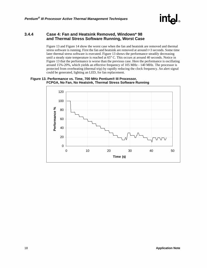
3.4.4 Case 4: Fan and Heatsink Removed, Windows* 98 and Thermal Stress Software Running, Worst Case
Figure 13 and Figure 14 show the worst case when the fan and heatsink are removed and thermal stress software is running. First the fan and heatsink are removed at around t=3 seconds. Some time later thermal stress software is executed. Figure 13 shows the performance steadily decreasing until a steady state temperature is reached at 65° C. This occurs at around 40 seconds. Notice in Figure 13 that the performance is worse than the previous case. Here the performance is oscillating around 15%-20%, which yields an effective frequency of 105 MHz - 140 MHz. The processor is protected from overheating (thermal trip) by rapidly reducing the clock frequency. An alert signal could be generated, lighting an LED, for fan replacement.
Figure 13. Performance vs. Time, 700 MHz Pentium® III Processor, FCPGA, No Fan, No Heatsink, Thermal Stress Software Running
0
20
40
60
80
100
120
0 10 20 30 40 50
Time (s)
Per
form
ance
%
0
20
40
60
80
100
120
0 10 20 30 40 50
Time (s)
Per
form
ance
%
18 Application Note

Pentium® III Processor Active Thermal Management Techniques
4.0 Customizing the Source Code
The source code can be modified for your application. For example, to change the threshold temperature, one constant would need to be changed: TEMP_HI. A duty cycle decrement/increment value of 5% was chosen (which is 13 decimal in an 8-bit range). Also, the initial duty cycle was arbitrarily chosen to be 80% (204 decimal). These values can be changed by editing the assembly source code and updating the constants listed in Table 1. The table lists constants that control the clock throttling routine:
There are several files that make up the clock throttling program. Table 2 describes each file.
Figure 14. TJunction vs. Time, 700 MHz Pentium® III Processor, FCPGA,No Fan, No Heatsink, Thermal Stress Software Running
0
10
20
30
40
50
60
70
80
90
100
0 10 20 30 40 50
Time (s)
TJ
(C)
0
10
20
30
40
50
60
70
80
90
100
0 10 20 30 40 50
Time (s)
TJ
(°C
)
Table 1. Clock Throttle Constants
Constant Init Purpose
DC_DEC_VALUE 13Duty cycle decrement value. Decrementing the duty cycle by 13, in an 8-bit PWM, will yield a 5% change in duty cycle.
DC_INIT 204 Duty cycle initialization value yields approximately 80% duty cycle with 8-bit PWM.
TEMP_HI 65 Arbitrary threshold of 65° C.
Application Note 19

Pentium® III Processor Active Thermal Management Techniques
For more information, see the following references:
5.0 Summary
Active thermal management techniques using an embedded microcontroller are very effective and easily implemented. The benefit of throttling the clock with a strictly hardware solution is that the solution is operating system software independent. With some analysis and experimentation, a more efficient algorithm could be used to throttle the clock. These solutions should be tailored to the specific application. This application note provides a template and example to get started with developing a custom clock throttling hardware solution.
Table 2. File Types and Purpose for Clock Throttling Program
Filename Type Purpose
mastri2c.asm assembly Main file that contains the control loop for the clock throttling routine.
i2ccomm.asm assembly Contains I2C master routines - see comments in file for subroutines.
init.asm assembly Initializes ports.
mastri2c.inc include Main routine register type declarations.
flags.inc include Flag bit declarations for I2C status, PWM status, etc.
i2ccomm.inc include Defines variables used in I2C routines.
i2ccomm1.inc include Defines the I2C function and variable types and scope for linker.
max1617a.inc include Defines command constants for MAX1617A.
p16f876.inc include Defines registers, etc. for microcontroller.
16f873.lkr linker Linker script file.
82371AB PCI-to ISA/IDE Xcelerator (PIIIX4) datasheet (order number 290562)
Intel 82371EB (PIIIX4E) Specification Update (order number 290635)
SMBus 1.1 Specifications can be found at the following Web site:http://www.sbs-forum.org/smbus/specs/
For more information on the MAX1617A temperature sensor, see the following Web site: http://www.maxim-ic.com/
20 Application Note

Pentium® III Processor Active Thermal Management Techniques
Appendix A Software Listings
;*********************************************************************; Filename: mastri2c.asm *; Date: 04/04/2000 *; Revision: 005 *; -004 *; -adds duty cycle variable PWM_DC. This DC register *; will be decreased if the temperature keeps rising past 65 deg. *; -If temp falls below threshold then Duty Cycle = 100% *; *; -005 Increases Duty Cycle by 5% if temp falls below threshold *; *; *; Tools: MPLAB 5.00.00 *; MPLINK 2.00.11 *; MPASM 2.40.00 *; *; *;**********************************************************************; *; System files required: *; *; mastri2c.asm *; i2ccomm.asm *; init.asm *; *; mastri2c.inc *; i2ccomm.inc *; i2ccomm1.inc *; flags.inc *; *; p16f876.inc *; 16f873.lkr (modified for interrupts) *; *;******************************************************************** *; *; Notes: *; *
*; Device Fosc -> 4.00MHz *;WDT -> off *;Brownout -> on *;Powerup timer -> on *;Code Protect -> off *; *; Interrupt sources - *; 1. I2C events (valid events) *; 2. I2C Bus Collision *; *; *; *;*********************************************************************
list p=16f876 ; list directive to define processor#include <p16f876.inc> ;processor specific variable definitions__CONFIG (_CP_OFF & _WDT_OFF & _BODEN_ON & _PWRTE_ON & _HS_OSC & _WRT_ENABLE_ON & _LVP_OFF & _CPD_OFF)
#include “mastri2c.inc” ;#include “i2ccomm1.inc” ; required include file #include “max1617a.inc”error level -302
Application Note 21

Pentium® III Processor Active Thermal Management Techniques
#define ADDRESS 0x4e ;Slave I2C address#define TEMP_HI 0x41 ; Temperature High threshold is 65 deg C
#define INIT_DC 100 ; Initial duty cycle is 100%, full speed
DC_DEC_VALUE equ 0x0D ; 8 bit PWM, duty cycle decrement value 5% of256
DC_INIT equ 0xCC ; initialize duty to 80%
;----------------------------------------------------------------------; ********************* RESET VECTOR LOCATION ********************;----------------------------------------------------------------------RESET_VECTOR CODE 0x000 ; processor reset vector
movlw high start ; load upper byte of ‘start’ labelmovwf PCLATH ; initialize PCLATHgoto start ; go to beginning of program
;----------------------------------------------------------------------; ******************* INTERRUPT VECTOR LOCATION *******************;----------------------------------------------------------------------INT_VECTOR CODE 0x004 ; interrupt vector location
movwf w_temp ; save off current W register contentsmovf STATUS,w ; move status register into W registerclrf STATUS ; ensure file register bank set to 0movwf status_temp ; save off contents of STATUS registermovf PCLATH,wmovwf pclath_temp ; save off current copy of PCLATHclrf PCLATH ; reset PCLATH to page 0
; TEST FOR COMPLETION OF VALID I2C EVENT banksel PIE1 ; select SFR bankbtfss PIE1,SSPIE ; test if interrupt is enabledgoto test_buscoll banksel PIR1 ; select SFR bankbtfss PIR1,SSPIF ; test for SSP H/W flaggoto test_buscoll ; no, bcf PIR1,SSPIF ; clear SSP H/W flagcall service_i2c
; TEST FOR I2C BUS COLLISION EVENTtest_buscoll
banksel PIE2 ; select SFR bankbtfss PIE2,BCLIE ; test if interrupt is enabledgoto timer1testbanksel PIR2 ; select SFR bankbtfss PIR2,BCLIF ; test if Bus Collision occuredgoto timer1testbcf PIR2,BCLIF ; clear Bus Collision H/W flagcall service_buscoll ; service bus collision error
timer1testbanksel PIE1btfss PIE1,TMR1IEgoto exit_isrbanksel PIR1btfss PIR1,TMR1IFgoto exit_isrbcf PIR1,TMR1IF ;timer1 rolled over
banksel sflag_eventbsf sflag_event,tmr1_ovr ;set the timer1 overflow flag
22 Application Note

Pentium® III Processor Active Thermal Management Techniques
banksel timer1countincf timer1count,f
movlw 0x02banksel PORTBxorwf PORTB
exit_isr clrf STATUS ; ensure file register bank set to 0movf pclath_temp,wmovwf PCLATH ; restore PCLATHmovf status_temp,w ; retrieve copy of STATUS registermovwf STATUS ; restore pre-isr STATUS register
contentsswapf w_temp,f ;swapf w_temp,w ; restore pre-isr W register contentsretfie ; return from interrupt
;----------------------------------------------------------------------; ******************* MAIN CODE START LOCATION ******************;----------------------------------------------------------------------
MAIN CODE
;***********************************************************************;* Convert Twos complement # to four ascii chars including sign ;* INPUT: twos_num = twos complement byte number;* OUTPUT: sign_num = + or - ascii sign;* hundreds_num = the hundreds place in ASCII;* tens_num = the tens place in ASCII;* ones_num = the ones place in ASCII;* twos_num,w,w_temp,count = destroyed;************************************************************************convert_twos
btfss twos_num,7 ; contains 8-bit twos complementgoto sign_positivemovlw ‘-’movwf sign_num ; store neg sign in ascii
comf twos_num,w ; complement twos # addlw 1 ; add 1, to convert to integermovwf twos_num ; save integergoto get_digits
sign_positive movlw ‘+’movwf sign_num
get_digits
movlw d’100’ movwf w_tempcall get_digitmovwf hundreds_nummovlw d’10’movwf w_tempcall get_digitmovwf tens_nummovlw 0x30addwf twos_num,w
Application Note 23

Pentium® III Processor Active Thermal Management Techniques
movwf ones_numreturn
get_digitclrf count
get_digit_loop subwf twos_num,wbtfss STATUS,C ; when C = 1 result is postivegoto get_digit_exitincf count,f ; result is positve, increment placemovwf twos_nummovf w_temp,w goto get_digit_loop
get_digit_exitmovf count,waddlw 0x30 ; convert num 0-9 to ascii
return
;**** Initialize the USART *******init_USART
movlw d’103’ ; 2400 baud @ 4MHz, brgh=1banksel SPBRGmovwf SPBRGbsf TXSTA,BRGHbanksel RCSTAbsf RCSTA,SPEN ;enable the serial portreturn
;***********************************************************;* Start;***********************************************************start
call init_ports ; initialize Portscall init_i2c ; initialize I2C modulecall init_vars ; initialize variablescall init_USART
;************banksel Str_Highmovlw high Welcome_Msgmovwf Str_Highmovlw low Welcome_Msgmovwf Str_Lowcall Puts
call Init_Interrupt_Masksmovlw b’00101001’ ;1:4 prescale, osc enabled,
; synch, intern, enable timer1banksel T1CONmovwf T1CON
movlw RCRA ; read conversion rate bytebanksel Max1617_Cmdmovwf Max1617_Cmdcall Send_Command_Max1617call Display_Max1617_Results ; print out conversion rate
movlw WCRW ; write conversion rate bytebanksel Max1617_Cmdmovwf Max1617_Cmdmovlw 0x07 ; 125ms sample periodbanksel Max1617_Datamovwf Max1617_Databanksel i2c_rwbsf i2c_rw,rw ; write data, rw = 1
24 Application Note

Pentium® III Processor Active Thermal Management Techniques
bcf i2c_rw,stopcall Send_Command_Max1617
movlw RCRA ; Read conversion rate bytebanksel Max1617_Cmdmovwf Max1617_Cmdcall Send_Command_Max1617call Display_Max1617_Results ; print conversion rate byte
banksel timer1countclrf timer1count
Send_Tempmovlw RRTE ; read remote temperaturebanksel Max1617_Cmdmovwf Max1617_Cmd ; Save which command we usedcall Send_Command_Max1617call Display_Max1617_Results
banksel read_stringmovlw TEMP_HI ; Is temp > TEMP_HI deg C ?subwf read_string,wbtfsc STATUS,C ; If C=0, result is negetive,
temp< TEMP_HI thresholdgoto Throttlebanksel sflag_eventbtfss sflag_event,pwm ; check if pwm runninggoto Send_Temp ; if not then continue
movlw DC_DEC_VALUE ; increase duty cycle by DC_DEC_VALUE
addwf PWM_DCbtfsc STATUS,C ; check if carry occurredgoto Turn_Off_PWM call Load_DC_Registercall Display_Duty_Cyclegoto Send_Temp
Turn_Off_PWMbcf sflag_event,pwm ; clear pwm flagbanksel PWM_DCmovlw 0xFFmovwf PWM_DC
banksel PORTCbsf PORTC,2 ; STPCLK# = 1, onbanksel CCP1CONclrf CCP1CON ; PWM off
goto Send_Temp
;*******************************************************************;* PWM setup;*******************************************************************Throttle
banksel sflag_eventbtfsc sflag_event,pwmgoto Continue_PWMbsf sflag_event,pwmbanksel PR2 ; first time here, enable PWMmovlw 0x3F ; 10 bit modemovwf PR2 ;set period
Application Note 25

Pentium® III Processor Active Thermal Management Techniques
banksel PWM_DCmovlw DC_INIT ; Initialize Duty Cyclemovwf PWM_DC
banksel T2CONmovlw b’00000100’ ;enable timer2movwf T2CON
banksel timer1countclrf timer1count
goto Start_PWMContinue_PWM
banksel timer1count
btfss timer1count,3 ; did timer1 roll over 8 times?goto Send_Temp ;return
clrf timer1count
Start_PWM
movlw DC_DEC_VALUE ; duty cycle decrement valuebanksel PWM_DCsubwf PWM_DC,f ; Duty Cycle = Duty Cycle - decrement
valuebtfss STATUS,C ; result negativeclrf PWM_DC ; if C=0. Set DC to 0 %
call Load_DC_Registercall Display_Duty_Cycle
goto Send_Temp
;*******************************************************************; MAIN LOOP BEGINS HERE;******************************************************************* Send_Command_Max1617
banksel INTCONbsf INTCON,PEIE ; enable peripheral interruptbsf INTCON,GIE ; enable global interruptbanksel sflag_event
Timer1_Overflow_Loop
banksel sflag_eventbtfss sflag_event,tmr1_ovrgoto Timer1_Overflow_Loopbcf sflag_event,tmr1_ovr
banksel Max1617_Cmdmovf Max1617_Cmd,wbanksel write_stringmovwf write_stringcall Init_Interrupt_Maskscall service_i2c ; kick off start condition
Send_Command_Loop
banksel eflag_event ; select SFR bankbtfsc eflag_event,ack_error; test for ack error event flagcall service_ackerror ; service ack error
banksel sflag_event ; select SFR bank btfss sflag_event,rw_done ; test if read/write cycle complete
goto Send_Command_Loop ; goto main loop
26 Application Note

Pentium® III Processor Active Thermal Management Techniques
bcf sflag_event,rw_done
call init_vars ; re-initialize variablesbanksel INTCONbcf INTCON,GIE ;disable interrupts for displaybcf INTCON,PEIE
return Display_Max1617_Results
movlw high (Display_Cmd_Jump + 1); fetch upper byte of jump table address
movwf PCLATH ; load into upper PC latch
banksel Max1617_Cmd ; recall command for jump table lookup
decf Max1617_Cmd,waddlw low (Display_Cmd_Jump + 1)btfsc STATUS,C ; skip if carry didn’t occurincf PCLATH,f ; otherwise add carry
Display_Cmd_Jump movwf PCL ; index into state machine jump tablegoto Display_Remote_Temp ; RRTE = 0x01 goto Display_Status_Reg ; RSL = 0x02goto Display_Configuration ; RCL = 0x03goto Display_Conversion ; RCRA = 0x04 conversion rategoto Display_Local_THIGH ; RLHN = 0x05goto Display_Local_TLOW ; RLLI = 0x06goto Display_Remote_THIGH ; RRHI = 0x07goto Display_Remote_TLOW ; RRLS = 0x08goto Display_Write_Config ; WCA = 0x09goto Display_Write_Conv ; WCRW = 0x0Agoto Display_Write_Local_THIGH ; WLHO = 0x0Bgoto Display_Write_Local_TLOW ; WLLM = 0x0Cgoto Display_Write_Remote_THIGH ; WRHA = 0x0Dgoto Display_Write_Remote_TLOW ; WRLN = 0x0E
;***********************************************************************;* Display Temp;* This routine will output the ASCII chars to the USART which;* will be displayed on the terminal. ;***********************************************************************Display_Remote_Temp ; RRTE = 0x01
banksel read_stringmovf read_string,wbanksel twos_nummovwf twos_numcall convert_twoscall Display_Twos_Nummovlw 0x0Acall Putc;linefeed
return
;*******************************************************************************;* Load DC Register - This routine takes the 8-bit duty cycle value in PWM_DC;* and places it into the 10-bit DC registers.;* CCP1CON, CCP1X,CCP1Y are loaded with the two lsbs;* CCPR1L is loaded with the upper 6 bits.;*;*******************************************************************************
Application Note 27

Pentium® III Processor Active Thermal Management Techniques
Load_DC_Registerbanksel CCP1CONmovlw b’00111100’iorwf CCP1CON ; pre-condition two LSBs CCP1X,CCP1Y
with 1’s ; also set PWM mode
banksel PWM_DCmovf PWM_DC,wmovwf temp_hold
btfss PWM_DC,0 ; set or clear LSBs for duty cyclegoto clear_lsb0
check_lsb1 banksel PWM_DCbtfss PWM_DC,1goto clear_lsb1goto Load_DC_Register_Exit
clear_lsb0banksel CCP1CONbcf CCP1CON,4 ; clear lsb 0goto check_lsb1
clear_lsb1 banksel CCP1CONbcf CCP1CON,5
Load_DC_Register_Exit
banksel PWM_DCbcf STATUS,Crrf PWM_DC,fbcf STATUS,Crrf PWM_DC,w ; rotate right to align with DC
register banksel CCPR1L ; load upper 6 bits of DCmovwf CCPR1L
movf temp_hold,wmovwf PWM_DC
return ; return from Load_DC_Register
;*********************************************************************;* Display Duty Cycle;* This routine converts the 8-bit duty cycle register to an ASCII;* decimal number. Then it displays out out the RS232.;*********************************************************************Display_Duty_Cycle
banksel PWM_DCmovf PWM_DC,wbanksel twos_num ; convert duty cycle to ASCIImovwf twos_numcall get_digits
movlw ‘D’ ; Display duty cycle value in decimalcall Putc ; absolute value not a percentagemovlw ‘C’call Putcmovlw ‘=’call Putcbanksel hundreds_nummovf hundreds_num,wcall Putc
28 Application Note

Pentium® III Processor Active Thermal Management Techniques
banksel tens_nummovf tens_num,wcall Putc
banksel ones_nummovf ones_num,wcall Putc
movlw 0x0a ; print linefeed and CRcall Putcmovlw 0x0dcall Putc
return ; return from Display_Duty_Cycle
;************************************************************************;* Diplay twos complement number;* INPUT: sign_num = ASCII sign either + or -;* hundreds_num, tens_num, ones_num = ASCII of place;* OUTPUT: USART;************************************************************************Display_Twos_Num
movf sign_num,wbanksel TXREGmovwf TXREG ; copy the sign into TXREGbanksel TXSTAbsf TXSTA,TXEN ;enable transmitter
SIGN_XMITbtfss TXSTA,TRMTgoto SIGN_XMIT
banksel hundreds_nummovf hundreds_num,wbanksel TXREGmovwf TXREGbanksel TXSTA
HUNDREDS_XMITbtfss TXSTA,TRMTgoto HUNDREDS_XMIT
banksel tens_nummovf tens_num,wbanksel TXREGmovwf TXREGbanksel TXSTA
TENS_XMITbtfss TXSTA,TRMTgoto TENS_XMIT
banksel ones_nummovf ones_num,wbanksel TXREGmovwf XREGbanksel TXSTA
ONES_XMITbtfss TXSTA,TRMTgoto ONES_XMIT
banksel TXREGmovlw 0x0D ;return charactermovwf TXREGbanksel TXSTA
CR_XMIT
Application Note 29
Pentium® III Processor Active Thermal Management Techniques
btfss TXSTA,TRMTgoto CR_XMITbanksel TXREG
return
;**************************************************************************************Display_Status_Reg ; RSL = 0x02
return
Display_Configuration ; RCL = 0x03
return
;*************************************************************************;* Display Conversion Rate as the control byte read;*************************************************************************Display_Conversion ; RCRA = 0x04 conversion rate
banksel Str_Highmovlw HIGH Conversion_Stringmovwf Str_Highbanksel Str_Lowmovlw LOW Conversion_Stringmovwf Str_Lowcall Puts
Get_Conversion_Rate_Stringmovlw high (Conversion_Jump +1)movwf PCLATHbanksel read_stringmovf read_string,wsublw 0x07 ; subtract w from literalbtfsc STATUS,C ; if c=1 result is 0 or positivegoto Display_Conversion_OKmovlw 0x08 ; print “reserved” if conversion rategoto DC_Reserved ; num returned is greater than 0x07
Display_Conversion_OKbanksel read_stringmovf read_string,w
DC_Reservedaddlw low (Conversion_Jump + 1)
btfsc STATUS,C ; skip if carry didn’t occurincf PCLATH,f ; otherwise add carry
Display_Conv_Jump movwf PCL ; index into state machine jump table
Conversion_Jumpmovwf PCLgoto P16seconds ; 0goto P8seconds ; 1goto P4seconds ; 2goto P2seconds ; 3goto P1second ; 4goto P0_5seconds ; 5goto P0_25seconds ; 6goto P0_125seconds ; 7goto Preserved ; 8
30 Application Note

Pentium® III Processor Active Thermal Management Techniques
P16secondsmovlw ‘1’call Putcmovlw ‘6’call Putcgoto Display_Conversion_Return
P8secondsmovlw ‘8’call Putcgoto Display_Conversion_Return
P4secondsmovlw ‘4’call Putcgoto Display_Conversion_Return
P2secondsmovlw ‘2’call Putcgoto Display_Conversion_Return
P1secondmovlw ‘1’call Putcgoto Display_Conversion_Return
P0_5secondsmovlw ‘0’call Putcmovlw ‘.’call Putcmovlw ‘5’call Putcgoto Display_Conversion_Return
P0_25secondsmovlw ‘0’call Putcmovlw ‘.’call Putcmovlw ‘2’call Putcmovlw ‘5’call Putcgoto Display_Conversion_Return
P0_125secondsmovlw ‘0’call Putcmovlw ‘.’call Putcmovlw ‘1’call Putcmovlw ‘2’call Putcmovlw ‘5’call Putcgoto Display_Conversion_Return
Preservedmovlw low (Reserved_String)banksel Str_Lowmovwf Str_Lowmovlw high (Reserved_String)movwf Str_Highcall Puts ; display “Reserved”
Display_Conversion_Return
Application Note 31

Pentium® III Processor Active Thermal Management Techniques
movlw low (Seconds_String)banksel Str_Lowmovwf Str_Lowmovlw high (Seconds_String)movwf Str_Highcall Puts ; display “Seconds”
movlw 0x0Dcall Putcmovlw 0x0A ; xmit linefeedcall Putc
return
Display_Local_THIGH ; RLHN = 0x05
return
Display_Local_TLOW ; RLLI = 0x06
return
;**************************************************************************;* Display remote TLOW limit;**************************************************************************Display_Remote_THIGH ; RRHI = 0x07
banksel Str_Highmovlw high RTHIGH_Stringmovwf Str_Highmovlw low RTHIGH_Stringmovwf Str_Lowcall Puts
call Display_Remote_Temp ; Print out Remote TLOW limitmovlw 0x0Acall Putc ; linefeed
return
;**************************************************************************;* Display remote TLOW limit;**************************************************************************Display_Remote_TLOW ; RRLS = 0x08
banksel Str_Highmovlw high RTLOW_Stringmovwf Str_Highmovlw low RTLOW_Stringmovwf Str_Lowcall Puts
call Display_Remote_Temp ; Print out Remote TLOW limitmovlw 0x0Acall Putc ; linefeed
return
Display_Write_Config ; WCA = 0x09
return
Display_Write_Conv ; WCRW = 0x0A
32 Application Note

Pentium® III Processor Active Thermal Management Techniques
return
Display_Write_Local_THIGH ; WLHO = 0x0B
return
Display_Write_Local_TLOW ; WLLM = 0x0C
return
Display_Write_Remote_THIGH ; WRHA = 0x0D
return
Display_Write_Remote_TLOW ; WRLN = 0x0E
return
;*******************************************************************;* Initialize Interrupt Masks;*******************************************************************
Init_Interrupt_Masks
banksel PIR1bcf PIR1,SSPIF ;clear SSPIFclrf PIR1banksel PIE1clrf PIE1bsf PIE1,SSPIE ; enable SSP H/W interrupt
banksel PIE2 ; select SFR bankbsf PIE2,BCLIE ; enable bus collision interrupt
banksel PIE1bsf PIE1,TMR1IE ; enable timer1 interrupt
return
;----------------------------------------------------------------------; *************** Bus Collision Service Routine ******************;----------------------------------------------------------------------service_buscoll
banksel i2cState ; select GPR bankclrf i2cState ; reset I2C bus state variablecall init_vars ; re-initialize variablesbanksel PORTBmovlw 0xC0 ;error code for bus collisionmovwf PORTB
return ;
;----------------------------------------------------------------------; ************* Acknowledge Error Service Routine ***************;----------------------------------------------------------------------service_ackerror
banksel eflag_event ; select SFR bankbcf eflag_event,ack_error ; reset acknowledge error event flagclrf i2cState ; reset bus state variablecall init_vars ; re-initialize variablesbanksel PORTBmovlw 0xE0 ;error code for ACK
Application Note 33

Pentium® III Processor Active Thermal Management Techniques
movwf PORTB
return
;----------------------------------------------------------------------; ***** INITIALIZE VARIABLES USED IN SERVICE_I2C FUNCTION ******;----------------------------------------------------------------------init_vars
movlw 1 ; byte count for max1617banksel write_count ; select GPR bankmovwf write_count ; initialize write countmovwf read_count ; initialize read count
movlw write_string ; get write string array addressmovwf write_ptr ; initialize write pointer
movlw read_string ; get read string placement addressmovwf read_ptr ; initialize read pointer
movlw ADDRESS ; get address of slavemovwf temp_address ; initialize temporary address hold reg
banksel eflag_event ; select GPR bankclrf eflag_event ; initialize event flag variablebtfss sflag_event,pwmclrf sflag_event ; initialize event flag variable
banksel i2c_rwclrf i2c_rw
banksel i2cStateclrf i2cStatereturn
;*****************************************************************;* Put string;* INPUT: Str_Low, Str_High - points to low and high portion of;* string address. ASCII string must be terminated;* with a null 0. String must be in ROM with RETLWs;* OUTPUT: To USART;*****************************************************************Puts
banksel TXSTAbsf TXSTA,TXEN ;enable transmitterbanksel indexclrf indexbanksel Str_High ; move high part of addressmovf Str_High,w ; of string into PCLATHmovwf PCLATH
Puts_lp
banksel TXSTAPuts_trmt
btfss TXSTA,TRMTgoto Puts_trmt ;no, loop
call Redirect_Callandlw 0xFF ; test if null char of 0btfsc STATUS,Zreturnbanksel TXREG
34 Application Note

Pentium® III Processor Active Thermal Management Techniques
movwf TXREG ;output character
banksel indexincf index,f
goto Puts_lp ;no, loopreturn ;all displayed, finished
Redirect_Callbanksel Str_Lowmovf Str_Low,wmovwf PCL ; goto string table
PutsErrorbanksel PORTBmovlw 0xFEmovwf 0xFEgoto $
;*****************************************************************;* Put char;* INPUT: w = character in ASCII to output;* OUTPUT: To USART;*****************************************************************Putc
banksel TXREGmovwf TXREGbanksel TXSTA
putc_xmitbtfss TXSTA,TRMTgoto putc_xmitreturn
Debug1banksel Str_Highmovlw high Debug1_Stringmovwf Str_Highmovlw low Debug1_Stringmovwf Str_Lowcall Putsreturn
Debug2banksel Str_Highmovlw high Debug2_Stringmovwf tr_Highmovlw low Debug2_Stringmovwf Str_Lowcall Putsreturn
;--------------------------------------------------------------------
CODE 0x300Welcome_Msg
banksel indexmovf index,waddlw low (Welcome_Msg + 5)movwf PCLDT “Clock throttling example using
MAX1617A and PIC16F873. rev 1.0”,0x0D,0x0A,0
;******************************************;**** Conversion Periods ******************
Conversion_Stringbanksel indexmovf index,w
Application Note 35

Pentium® III Processor Active Thermal Management Techniques
addlw low (Conversion_String + 5)movwf PCLDT “Conversion Period: “,0
Seconds_Stringbanksel indexmovf index,waddlw low (Seconds_String + 5)movwf PCLDT “ seconds”,0
Reserved_Stringbanksel indexmovf index,waddlw low (Reserved_String + 5)movwf PCLDT “Reserved”,0
RTLOW_Stringbanksel indexmovf index,waddlw low (RTLOW_String+ 5)movwf PCLDT “Remote TLOW = “,0
RTHIGH_Stringbanksel indexmovf index,waddlw low (RTHIGH_String+ 5)movwf PCL
DT“Remote THIGH = “,0
Debug1_Stringbanksel indexmovf index,waddlw low (Debug1_String + 5)movwf PCLDT “Here 1”,0x0A,0x0D,0
Debug2_Stringbanksel indexmovf index,waddlw low (Debug2_String + 5)movwf PCLDT “Here 2”,0x0a,0x0d,0
END ; required directive
36 Application Note

Pentium® III Processor Active Thermal Management Techniques
A.1 Init.asm
;*********************************************************************; *; Implementing Master I2C with the MSSP module on a PICmicro *; *;*********************************************************************; *; Filename: init.asm *; Date: 04/04/2000 *; Revision: 1.00 *; *; Tools: MPLAB 5.00.00 *; MPLINK 2.00.11 *; MPASM 2.40.00 *; *; *; *;*********************************************************************; *; Files required: *; *; init.asm *; *; p16f873.inc *; *; *;*********************************************************************; *; Notes: *; *; *;********************************************************************/
#include <p16f873.inc> ; processor specific variable definitionserrorlevel -302
GLOBAL init_ports ; make function viewable for other modules
;----------------------------------------------------------------------; ******************* INITIALIZE PORTS *************************;----------------------------------------------------------------------INIT_CODE CODE
init_portsbanksel PORTA ; select SFR bankclrf PORTA ;clrf PORTB ;
movlw 0xffmovwf PORTC
bsf STATUS,RP0 ; select SFR bankmovlw b’00001111’ ;movwf ADCON1 ;clrf TRISB ;clrf TRISA ; movlw b’00011000’ ;RC4,C3 are SDA,SCLmovwf TRISC ;RC2 is PWM1bcf STATUS,RP0
return
END ; required directive
Application Note 37

Pentium® III Processor Active Thermal Management Techniques
A.2 i2ccomm.asm
;********************************************************************; *; *; Implementing Master I2C with the MSSP module on a PICmicro *; *;********************************************************************; *; Filename: i2ccomm.asm *; Date: 04/04/2000 *; Revision: 1.00 *
*; Tools: MPLAB 5.00.00 *; MPLINK 2.00.11 *; MPASM 2.40.00 *; *;********************************************************************; *; Files required: *; *; i2ccomm.asm *; *; i2ccomm.inc *; flags.inc (referenced in i2ccomm.inc file) *; i2ccomm1.inc (must be included in main file) *; p16f873.inc *; *;********************************************************************; *; Notes: The routines within this file are used to read from *; and write to a Slave I2C device. The MSSP initialization *; function is also contained within this file. *; *;*******************************************************************/
#include <p16f873.inc> ; processor specific definitions#include "i2ccomm.inc" ; required include fileerrorlevel -302
#define FOSC D’4000000’ ; define FOSC to PICmicro#define I2CClock D’400000’ ; define I2C bite rate#define ClockValue ( ((FOSC/I2CClock)/4) -1) ;
;----------------------------------------------------------------------; *********************** I2C Service *************************;----------------------------------------------------------------------I2C_COMM CODEservice_i2c; pagesel i2c_idle ; ensure PCLATH is set for the section; call i2c_idle ; verify I2C idle check
movlw high I2CJump ; fetch upper byte of jump table addressmovwf PCLATH ; load into upper PC latchmovlw i2cSizeMaskbanksel i2cState ; select GPR bankandwf i2cState,w ; retrieve current I2C stateaddlw low (I2CJump + 1) ; calc state machine jump addr into Wbtfsc STATUS,C ; skip if carry occuredincf PCLATH,f ; otherwise add carry
I2CJump ; address where jump table branch occurs, this addr also used in fill movwf PCL ; index into state machine jump table
38 Application Note

Pentium® III Processor Active Thermal Management Techniques
; jump to processing for each state = i2cState value for each state
goto WrtStart ; write start sequence = 0goto SendWrtAddr ; write address, R/W=1 = 1goto WrtAckTest ; test ack,write data = 2
goto WrtStop ; do stop if done = 3
goto ReadStart ; write start sequence = 4goto SendReadAddr ; write address, R/W=0 = 5goto ReadAckTest ; test acknowledge after address = 6
goto ReadData ; read more data = 7goto ReadStop ; generate stop sequence = 8
I2CJumpEnd Fill (return), (I2CJump-I2CJumpEnd) + i2cSizeMask
;----------------------------------------------------------------------; ********************* Write data to Slave *********************;----------------------------------------------------------------------; Generate I2C bus start condition [ I2C STATE -> 0 ]WrtStart
banksel write_ptr ; select GPR bankmovf write_ptr,w ; retrieve ptr addressmovwf FSR ; initialize FSR for indirect accessincf i2cState,f ; update I2C state variablebanksel SSPCON2 ; select SFR bankbsf SSPCON2,SEN ; initiate I2C bus start condition
return ;
; Generate I2C address write (R/W=0) [ I2C STATE -> 1 ]SendWrtAddr
banksel temp_address ; select GPR bankbcf STATUS,C ; ensure carry bit is clearrlf temp_address,w ; compose 7-bit addressincf i2cState,f ; update I2C state variablebanksel SSPBUF ; select SFR bankmovwf SSPBUF ; initiate I2C bus write conditionreturn ;
; Test acknowledge after address and data write [ I2C STATE -> 2 ]WrtAckTest
banksel SSPCON2 ; select SFR bankbtfss SSPCON2,ACKSTAT ; test for acknowledge from slavegoto WrtData ; go to write data modulebanksel eflag_event ; select GPR bankbsf eflag_event,ack_error; set acknowledge errorclrf i2cState ; reset I2C state variablebanksel SSPCON2 ; select SFR bankbsf SSPCON2,PEN ; initiate I2C bus stop conditionreturn ;
; Generate I2C write data conditionWrtData
movf INDF,w ; retrieve byte into wbanksel write_count ; select GPR bankdecfsz write_count,f ;test if all done with writesgoto send_byte ; not end of stringincf i2cState,f ; update I2C state variable
send_bytebanksel SSPBUF ; select SFR bankmovwf SSPBUF ; initiate I2C bus write conditionincf FSR,f ; increment pointerreturn ;
; Generate I2C bus stop condition [ I2C STATE -> 3 ]
Application Note 39

Pentium® III Processor Active Thermal Management Techniques
WrtStopbanksel SSPCON2 ; select SFR bankbtfss SSPCON2,ACKSTAT ; test for acknowledge from slavegoto no_error ; bypass setting error flagbanksel eflag_event ; select GPR bankbsf eflag_event,ack_error; set acknowledge errorclrf i2cState ; reset I2C state variablegoto write_or_read
no_errorbanksel i2cState ; select GPR bankincf i2cState,f ; update I2C state variable for read
write_or_read
banksel i2c_rwbtfss i2c_rw,rw ; read = 0, write = 1goto ReadStart ; if it is a read then continue to nxt
statebtfsc i2c_rw,stopgoto ReadStopbankse Max1617_Data movf Max1617_Data,wbanksel SSPBUF ; select SFR bankmovwf SSPBUF ; initiate I2C bus write conditionbanksel i2cStatemovlw 0x03 ;switch to check ack after data writemovwf i2cStatebanksel i2c_rwbsf i2c_rw,stop ;set up for stop on next state
return
;----------------------------------------------------------------------; ********************* Read data from Slave *********************;----------------------------------------------------------------------; Generate I2C start condition [ I2C STATE -> 4 ]ReadStart
banksel read_ptr ; select GPR bankmovf read_ptr,W ; retrieve ptr addressmovwf FSR ; initialize FSR for indirect accessincf i2cState,f ; update I2C state variablebanksel SSPCON2 ; select SFR bankbsf SSPCON2,RSEN ; initiate I2C bus REstart conditionreturn ;
; Generate I2C address write (R/W=1) [ I2C STATE -> 5 ]SendReadAddr
banksel temp_address ; select GPR bankbsf STATUS,C ; ensure cary bit is clearrlf temp_address,w ; compose 7 bit addressincf i2cState,f ; update I2C state variablebanksel SSPBUF ; select SFR bankmovwf SSPBUF ; initiate I2C bus write conditionreturn ;
; Test acknowledge after address write [ I2C STATE -> 6 ]ReadAckTest
banksel SSPCON2 ; select SFR bankbtfss SSPCON2,ACKSTAT ; test for not acknowledge from slavegoto StartReadData ; good ack, go issue bus readbanksel eflag_event ; ack error, so select GPR bankbsf eflag_event,ack_error; set ack error flagclrf i2cState ; reset I2C state variablebanksel SSPCON2 ; select SFR bankbsf SSPCON2,PEN ; initiate I2C bus stop conditionreturn
StartReadData
40 Application Note

Pentium® III Processor Active Thermal Management Techniques
bsf SSPCON2,RCEN ; generate receive conditionbanksel i2cState ; select GPR bankincf i2cState,f ; update I2C state variablereturn
; Read slave I2C [ I2C STATE -> 7 ]ReadData
banksel SSPBUF ; select SFR bankmovf SSPBUF,w ; save off byte into Wbanksel read_count ; select GPR bankdecfsz read_count,f ; test if all done with readsgoto SendReadAck ; not end of string so send ACK
; Send Not AcknowledgeSendReadNack
movwf INDF ; save off null characterincf i2cState,f ; update I2C state variable
banksel SSPCON2 ; select SFR bankbsf SSPCON2,ACKDT ; acknowledge bit state to send (not ack)bsf SSPCON2,ACKEN ;initiate acknowledge sequencereturn
; Send AcknowledgeSendReadAck
movwf INDF ; no, save off byteincf FSR,f ; update receive pointer
banksel SSPCON2 ; select SFR bankbcf SSPCON2,ACKDT ; acknowledge bit state to sendbsf SSPCON2,ACKEN ; initiate acknowledge sequencebtfsc SSPCON2,ACKEN ; ack cycle complete?goto $-1 ; no, so loop againbsf SSPCON2,RCEN ; generate receive conditionreturn ;
; Generate I2C stop condition [ I2C STATE -> 8 ]ReadStop
banksel SSPCON2 ; select SFR bankbcf PIE1,SSPIE ; disable SSP interruptbsf SSPCON2,PEN ; initiate I2C bus stop conditionbanksel i2cState ; select GPR bankclrf i2cState ; reset I2C state variablebsf sflag_event,rw_done ; set read/write done flag
return
;----------------------------------------------------------------------; ******************* Generic bus idle check ***********************;----------------------------------------------------------------------; test for i2c bus idle statei2c_idle
banksel SSPSTAT ; select SFR bankbtfsc SSPSTAT,R_W ; test if transmit is progress goto $-1 ; module busy so waitbanksel SSPCON2 ; select SFR bankmovf SSPCON2,w ; get copy of SSPCON2 for status bitsandlw 0x1F ; mask out non-status bitsbtfss STATUS,Z ; test for zero state, if Z set, bus is idlegoto $-3 ; bus is busy so test againreturn ; return to calling routine
Application Note 41

Pentium® III Processor Active Thermal Management Techniques
;----------------------------------------------------------------------; ******************* INITIALIZE MSSP MODULE *******************;----------------------------------------------------------------------
init_i2cbanksel SSPADD ; select SFR bankmovlw ClockValue ; read selected baud rate movwf SSPADD ; initialize I2C baud rate
bsf SSPSTAT,6 ; select I2C input levels for SMBUSbcf SSPSTAT,7 ; enable slew rate
; movlw b’00011000’ ;; iorwf TRISC,f ; ensure SDA and SCL are inputs; movwf TRISC
bcf STATUS,RP0 ; select SFR bankmovlw b’00111000’ ; movwf SSPCON ; Master mode, SSP enablereturn ; return from subroutine
END ; required directive
A.3 mastri2c.inc
;*********************************************************************; *; Filename: mastri2c.inc *; Date: 04/01/2000 *; Revision: 1.00 *; *; Tools: MPLAB 5.00.00 *; MPLINK 2.00.11 *; MPASM 2.40.00 *; *;*********************************************************************
;******* INTERRUPT CONTEXT SAVE/RESTORE VARIABLESINT_VAR UDATA 0x20 ; create uninitialized data "udata" sectionw_temp RES 1 ;status_temp RES 1 ;pclath_temp RES 1
INT_VAR1 UDATA 0xA0 ; reserve location 0xA0w_temp1 RES 1
;******* GENERAL PURPOSE VARIABLESGPR_DATA UDATAtemp_hold RES 1 ; temp variable for string compareptr1 RES 1 ; used as pointer in string compare ptr2 RES 1 ; used as pointer in string comparecount RES 1index RES 1sign_num RES 1hundreds_num RES 1tens_num RES 1ones_num RES 1twos_num RES 1timer1count RES 1
42 Application Note

Pentium® III Processor Active Thermal Management Techniques
Max1617_Cmd RES 1Str_High RES 1Str_Low RES 1PWM_DC RES 1
STRING_DATA UDATAwrite_string RES D’30’read_string RES D’30’
EXTERN init_ports ; reference linkage for function
A.4 i2ccomm.inc
;*********************************************************************; *; Filename: i2ccomm.inc *; Date: 04/04/2000 *; Revision: 1.00 *; *; Tools: MPLAB 5.00.00 *; MPLINK 2.00.11 *; MPASM 2.40.00 *; *;*********************************************************************; *; Notes: *; *; This file is to be included in the i2ccomm.asm file *; *; *;********************************************************************/
#include "flags.inc" ; required include file
i2cSizeMask EQU 0x0F
GLOBAL sflag_event ; make variable viewable for other modules GLOBAL eflag_event ; make variable viewable for other modulesGLOBAL i2cState ; make variable viewable for other modulesGLOBAL read_count ; make variable viewable for other modulesGLOBAL write_count ; make variable viewable for other modulesGLOBAL write_ptr ; make variable viewable for other modulesGLOBAL read_ptr ; make variable viewable for other modulesGLOBAL temp_address ; make variable viewable for other moduleGLOBAL init_i2c ; make function viewable for other modulesGLOBAL service_i2c ; make function viewable for other modulesGLOBAL i2c_rwGLOBAL Max1617_Data
;******* GENERAL PURPOSE VARIABLESGPR_DATA UDATAsflag_event RES 1 ; variable for i2c general status flagseflag_event RES 1 ; variable for i2c error status flagsi2cState RES 1 ; I2C state machine variableread_count RES 1 ; variable used for slave read byte countwrite_count RES 1 ; variable used for slave write byte countwrite_ptr RES 1 ; variable used for pointer (writes to)read_ptr RES 1 ; variable used for pointer (reads from)temp_address RES 1 ; variable used for passing address to functions
Application Note 43

Pentium® III Processor Active Thermal Management Techniques
i2c_rw RES 1Max1617_Data RES 1
;*********************************************************************; *; Additional notes on variable usage: *; *; The variables listed below are used within the function *; service_i2c. These variables must be initialized with the *; appropriate data from within the calling file. In this *; application code the main file is ’mastri2c.asm’. This file *; contains the function call to service_i2c. It also contains *; the function for initializing these variables, called ’init_vars’ *; *; To use the service_i2c function to read from and write to an *; I2C slave device, information is passed to this function via *; the following variables. *; *; *; The following variables are used as function parameters: *; *; read_count - Initialize this variable for the number of bytes *; to read from the slave I2C device. *; write_count - Initialize this variable for the number of bytes *; to write to the slave I2C device. *; write_ptr - Initialize this variable with the address of the *; data string to write to the slave I2C device. *; read_ptr - Initialize this variable with the address of the *; location for storing data read from the slave I2C *; device. *; temp_address - Initialize this variable with the address of the *; slave I2C device to communicate with. *; *; *; The following variables are used as status or error events *; *; sflag_event - This variable is implemented for status or *; event flags. The flags are defined in the file *; ’flags.inc’. *; eflag_event - This variable is implemented for error flags. The *; flags are defined in the file ’flags.inc’. *; *; *; The following variable is used in the state machine jump table. *; *; i2cState - This variable holds the next I2C state to execute. *; *;*********************************************************************
i2ccomm1.inc;*********************************************************************; *; Filename: i2ccomm1.inc *; Date: 04/04/2000 *; Revision: 1.00 *; *; Tools: MPLAB 5.00.00 *; MPLINK 2.00.11 *; MPASM 2.40.00 *; *;*********************************************************************; *; Notes: *; *; This file is to be included in the <main.asm> file. The *; <main.asm> notation represents the file which has the *; subroutine calls for the functions ’service_i2c’ and ’init_i2c’. *
44 Application Note

Pentium® III Processor Active Thermal Management Techniques
*; *; *;********************************************************************/
#include "flags.inc" ; required include file
GLOBAL write_string ; make variable viewable for other modulesGLOBAL read_string ; make variable viewable for other modules
EXTERN sflag_event ; reference linkage for variable EXTERN eflag_event ; reference linkage for variableEXTERN i2cState ; reference linkage for variableEXTERN read_count ; reference linkage for variableEXTERN write_count ; reference linkage for variableEXTERN write_ptr ; reference linkage for variableEXTERN read_ptr ; reference linkage for variableEXTERN temp_address ; reference linkage for variable
EXTERN init_i2c ; reference linkage for functionEXTERN service_i2c ; reference linkage for functionEXTERN i2c_rwEXTERN Max1617_Data
;*********************************************************************; *; Additional notes on variables declared as EXTERN *; *; The variables listed below are used within the function *; service_i2c. These variables must be initialized with the *; appropriate data from within the calling file. In this *; application code the main file is ’mastri2c.asm’. This file *; contains the function call to service_i2c. It also contains *; the function for initializing these variables, called ’init_vars’ *; *; To use the service_i2c function to read from and write to an *; I2C slave device, information is passed to this function via *; the following variables. *; *; *; The following variables are used as function parameters: *; *; read_count - Initialize this variable for the number of bytes *; to read from the slave I2C device. *; write_count - Initialize this variable for the number of bytes *; to write to the slave I2C device. *; write_ptr - Initialize this variable with the address of the *; data string to write to the slave I2C device. *; read_ptr - Initialize this variable with the address of the *; location for storing data read from the slave I2C *; device. *; temp_address - Initialize this variable with the address of the *; slave I2C device to communicate with. *; *; *; The following variables are used as status or error events *; *; sflag_event - This variable is implemented for status or *; event flags. The flags are defined in the file *; ’flags.inc’. *; eflag_event - This variable is implemented for error flags. The *; flags are defined in the file ’flags.inc’. *; *; *; The following variable is used in the state machine jumnp table. *; *
Application Note 45

Pentium® III Processor Active Thermal Management Techniques
; i2cState - This variable holds the next I2C state to execute. *; *;*********************************************************************
A.5 max1617a.inc
;Max1617A constants;4/24/00 - Rick Evans
NUMSTATES EQU 10 RRTE EQU 0x01 ;Command for reading remote temp sensorRSL EQU 0x02 ;Command for reading status regRCL EQU 0X03 ;Command for reading configuration byteRCRA EQU 0X04 ;Command for reading conversion rate byteRLHN EQU 0X05 ;Command for reading local THIGH limitRLLI EQU 0X06 ;Command for reading local TLOW limitRRHI EQU 0X07 ;Command for reading remote thigh limitRRLS EQU 0X08 ;Command for reading remote TLOW limitWCA EQU 0x09 ;Command for writing configuration regWCRW EQU 0x0A ;Command for writing conversion rate regWLHO EQU 0x0B ;Command for writing local THIGH limitWLLM EQU 0x0C ;Write local TLOW limitWRHA EQU 0x0D ;Command for writing remote THIGH limit regWRLN EQU 0x0E ;Command for writing remote TLOW limit reg
A.6 flags.inc
;*********************************************************************; *; Filename: flags.inc *; Date: 04/04/2000 *; Revision: 1.00 *; *; Tools: MPLAB 5.00.00 *; MPLINK 2.00.11 *; MPASM 2.40.00 *; *;*********************************************************************; *; Notes: *; *; This file defines the flags used in the i2ccomm.asm file. *; *; *;********************************************************************/
; bits for variable sflag_event#define sh1 0 ; place holder#define sh2 1 ; place holder#define sh3 2 ; place holder#define sh4 3 ; place holder#define sh5 4 ; place holder#define pwm 5 ; if pwm is enabled (clk throttling)#define tmr1_ovr 6 ; timer1 overflow#define rw_done 7 ; flag bit
; bits for variable eflag_event#define ack_error 0 ; flag bit#define eh1 1 ; place holder#define eh2 2 ; place holder#define eh3 3 ; place holder
46 Application Note

Pentium® III Processor Active Thermal Management Techniques
#define eh4 4 ; place holder#define eh5 5 ; place holder#define eh6 6 ; place holder#define eh7 7 ; place holder
; bits for variable i2c_rw#define rw 0 ; flag bit#define stop 1 ; stop flag bit for write data command#define rw2 2 ; place holder#define rw3 3 ; place holder#define rw4 4 ; place holder#define rw5 5 ; place holder#define rw6 6 ; place holder#define rw7 7 ; place holder
Application Note 47