Pentium 4 Pipe Lining
9
REPORT ON PENTIUN 4 PIPELINING Report on Pentium 4 pipelining Pentium 4 The Pentium 4 is a seventh-generation x86 architecture microprocessor produced by Intel and is based on the new CPU design, called the NetBurst architecture, since the Pentium Pro of 1995. The microarchitecture of NetBurst featured a very deep instruction pipeline, with the intention of scaling to very high frequencies. It also introduced the SSE2 instruction set for faster SIMD integer, and 64-bit floating point computation. Recent Pentium 4 models introduced new technological advances such as Hyper-Threading, a feature to make a physical CPU appears as two logical and virtual CPUs. Similar to previous Intel processors the Pentium 4 microprocessor uses the x86-32 bit instruction set, which is CISC (Complex Instruction Set Computing) based. In order to speed up the processor core easily, Intel break up the large complex instructions that comprise the instruction set into smaller bits (called micro-ops), which the processor can then execute (giving it certain RISC advantages). Needless to say, this new approach is something new in processor design, and should help the Pentium 4 to scale easier with the demand of increasing clock frequencies. The Pentium 4 is a completely new processor holding several new designs. Here is a highlight: 400 MHz Front Side Bus of 128 bit width Execution Trace Cache 20 KB L1 cache and 256 KB L2 The ALU (Arithmetical Logic Unit) runs at twice the clock speed New socket for simple motherboard design Clock frequencies from 1500 MHz 20 stages pipeline SSE2 and 128 bit MMX 42 millions of transistors New 423 pins socket design Dual Rambus memory channel with i850 chipset Only single processor mode available. Pipelining
-
Upload
api-3801329 -
Category
Documents
-
view
115 -
download
2
Transcript of Pentium 4 Pipe Lining

REPORT ON PENTIUN 4 PIPELINING
Report on Pentium 4 pipelining
Pentium 4
The Pentium 4 is a seventh-generation x86 architecture microprocessor produced by Intel and is based on the new CPU design, called the NetBurst architecture, since the Pentium Pro of 1995. The microarchitecture of NetBurst featured a very deep instruction pipeline, with the intention of scaling to very high frequencies. It also introduced the SSE2 instruction set for faster SIMD integer, and 64-bit floating point computation. Recent Pentium 4 models introduced new technological advances such as Hyper-Threading, a feature to make a physical CPU appears as two logical and virtual CPUs.
Similar to previous Intel processors the Pentium 4 microprocessor uses the x86-32 bit instruction set, which is CISC (Complex Instruction Set Computing) based. In order to speed up the processor core easily, Intel break up the large complex instructions that comprise the instruction set into smaller bits (called micro-ops), which the processor can then execute (giving it certain RISC advantages). Needless to say, this new approach is something new in processor design, and should help the Pentium 4 to scale easier with the demand of increasing clock frequencies.
The Pentium 4 is a completely new processor holding several new designs. Here is a highlight:
400 MHz Front Side Bus of 128 bit width Execution Trace Cache 20 KB L1 cache and 256 KB L2 The ALU (Arithmetical Logic Unit) runs at twice the clock speed New socket for simple motherboard design Clock frequencies from 1500 MHz 20 stages pipeline SSE2 and 128 bit MMX 42 millions of transistors New 423 pins socket design Dual Rambus memory channel with i850 chipset Only single processor mode available.
Pipelining
Pipelining is a technique to allow the processor to execute multiple instructions at the same time.
Pipelining improves performance
By executing multiple instructions in parallel we can realize:
o An effective CPI near 1 o Speedup near ‘n’ (number of stages in the pipe).

Problems associated with pipelining
Pipelining helps instruction bandwidth, not latency. Hazards associated with the pipelining limit performance.
1. Structural Hazard The processor needs more hardware resources
2. Data Hazard Need forwarding, compiler scheduling
3. Control Hazard Evaluate target and condition early, use delayed branch, branch
prediction. Increasing pipeline depth increases impact of hazards. Compilers can reduce the cost of hazards:
1. Load delay slots 2. Branch delay slots 3. Static branch prediction 4. Exceptions make pipelining harder 5. Floating Point (long latency operations) makes pipelining harder.
ISA design can make pipelining harder: 1. Variable length instructions 2. Complex addressing modes 3. Implicit condition codes 4. Writable code space
Pentium 4 Operation
• Fetch instructions form memory in order of static program• Translate instruction into one or more fixed length RISC instructions (micro-operations)• Execute micro-ops on superscalar pipeline
– Micro-operations may be executed out of order• Commit results of micro-ops to register set in original program flow order• Outer CISC shell with inner RISC core• Inner RISC core pipeline at least 20 stages
– Some micro-ops require multiple execution stages• Longer pipeline
The P4 can have up to 126 instructions in various stages of execution simultaneously. This way, the processor can have many more instructions on-chip for the out-of-order execution logic to examine for dependencies and then rearrange to be rapidly fired to the execution units.
Pipeline Structure of Pentium 4
The Pentium 4 Hyper pipelined technology enables high clock rates and frequency headroom to well above 1GHz, as the previous Intel architecture could not handle clock speeds above this limit. It uses a 20 stage deep pipelined design to enable significantly increased processor performance and frequency capability, and hence allowing processor speed to exceed the maximum speed limitation of the P6 architecture. Its pipeline provides high performance by optimizing for the common case of frequently executed instructions (Amdahl’s Law). This means that the most frequently executed instructions are decoded efficiently and executed with short latencies, allowing frequently encountered code sequences to be processed with high throughput.

By using techniques such as parallel execution, buffering, and speculation, stall penalties may be hidden. Instructions are executed dynamically, meaning that individual instruction execution time is not always deterministic.
The pipeline is a processor's assembly line. A longer pipeline creates "latency" problems, as in the case when an instruction gets misplaced at stage towards the final stages of the pipeline, resulting in the need to return back to stage one of the pipeline (more instructions are flushed). Effectively, this result in a lower average number of instructions successfully executed per clock cycle. However, longer pipelines allow processor designers to hit higher processor speeds. To compensate for the lower number of instructions executed per clock cycle, Intel has implemented a couple of features that reduce the inherent miss-prediction penalty. These are the Execution Trace Cache and the Dynamic Execution Engine.
Execution Trace Cache
The Netburst micro-architecture, implemented by the Pentium 4, can support up to three levels of on-chip cache. The first level (8KB L1) data cache handles data accesses, a second cache known as an Execution Trace Cache is used for instruction accesses, and a second-level cache (256KB L2 cache) is used to transfer the required data or instruction(s) to and from main memory.
This cache will hold commonly used instructions in the sequence that get executed meaning that the processor can avoid the need of continuously decoding the same instructions that it requires again more than once. With its ability to store 12000 micro-operations (decoded instructions), the Execution Trace Cache leads to an overall improvement in processor speed and providing the benefit of removing the pipeline decodes latency. Latency is eliminated because the execution engine can retrieve decoded operations from the cache directly, rather than fetching and decoding commonly used instructions over and over again.
The pipeline used within the Netburst micro-architecture contains three sections, including the in-order Front End, the out-of-order superscalar execution core and the in-order Retirement unit. These three pipeline stages in the Netburst architecture are shown in the figure given below and the explanation of each stage are provided below.
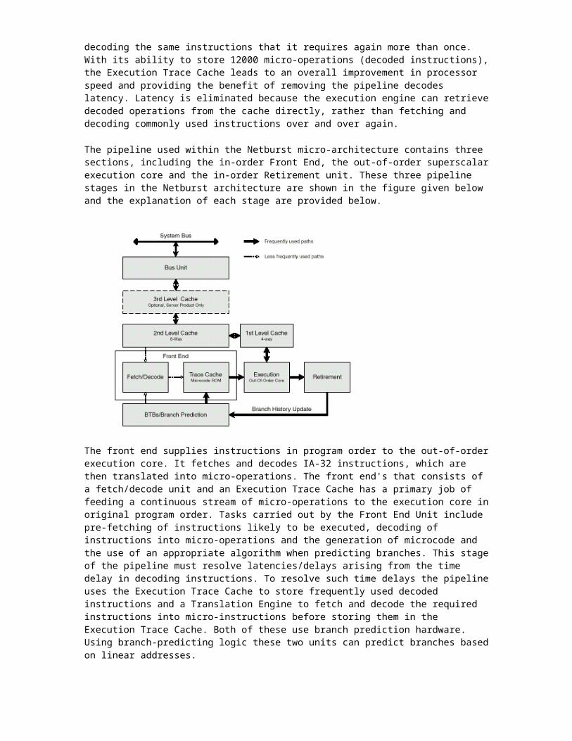
The front end supplies instructions in program order to the out-of-order execution core. It fetches and decodes IA-32 instructions, which are then translated into micro-operations. The front end's that consists of a fetch/decode unit and an Execution Trace Cache has a primary job of feeding a continuous stream of micro-operations to the execution core in original program order. Tasks carried out by the Front End Unit include pre-fetching of instructions likely to be executed, decoding of instructions into micro-operations and the generation of microcode and the use of an appropriate algorithm when predicting branches. This stage of the pipeline must resolve latencies/delays arising from the time delay in decoding instructions. To resolve such time delays the pipeline uses the Execution Trace Cache to store frequently used decoded instructions and a Translation Engine to fetch and decode the required instructions into micro-instructions before storing them in the Execution Trace Cache. Both of these use branch prediction hardware. Using branch-predicting logic these two units can predict branches based on linear addresses.
Out-of-Order Execution
The Out-of-Order Execution Core issues and aggressively arranges or re-orders micro-ops, to allow those micro-ops (with ready resources and inputs) to begin execution as early as possible to avoid wasting any time. Parallel execution allows the instructions to be executed out of order. This enables other instructions (typically held in a buffer) to execute while a micro-instruction may be waiting for data or a resource, and hence through parallel execution we resolve some pipeline delays. The Core can execute multiple instructions at a time in each of its 20 pipelines.
The in-order retirement unit ensures that the results of execution of the micro-operations are processed according to the order of the corresponding program to which it belongs. In addition all architectural states are updated by the retirement unit in accordance with the order of the original program. Any exceptions in the program must occur in the correct order and the system restarted after this point. After the result of a micro-instruction has been written to the destination, the micro-op becomes retired. The processor uses a reorder to buffer store completed micro-instructions and update the architectural states. Another functionality of the retirement unit is to keep track of branches and send updated branch target information to the Branch Target Buffer (BTB) where branch information is updated.
Branch Prediction
Branch prediction enables the processor to begin executing instructions long before the branch outcome is certain. A processor also experiences branch delays which is the penalty that is incurred in the absence of a correct prediction. For Pentium 4 processor, the branch delay for a correctly predicted instruction can be as few as zero clock cycles, and the branch delay for a miss-predicted branch is typically equivalent to the depth of the pipeline.
The branch prediction in the Intel NetBurst micro-architecture predicts all near branches, including conditional, unconditional calls and returns, and indirect branches. The following features help predicting branches more accurately and in reducing the cost of taken branches. Firstly we can dynamically predict the direction and target of branches based on the instructions' linear address using the Branch Target Buffer (BTB). This predicts the branch outcome before the branch instruction has been decoded and is always updated with the branch address. If, however, no dynamic prediction is available (or if it is invalid), we must statically predict the outcome based on the offset of the target, where a backward branch is predicted to be taken and a forward branch is predicted to be not taken. Return addresses are predicted using the 16-entry return address stack. The Return Stack can predict

return addresses for a series of procedure calls, hence increasing the benefit of unrolling loops containing function calls. Traces of instructions are built across predicted taken branches to avoid branch penalties.
Rapid Execution Engine
In the Pentium 4, two ALU (Arithmetic Logic Unit) and two AGU (Address Generation Unit) run at twice the processor speed. The introduction of the Rapid execution engine into the Pentium 4 serves to reduce the latency of basic integer instructions. The Netburst Execution Engine pushes the processor's Arithmetic Logic Units to twice the core frequency resulting in higher execution throughput and a reduced latency of execution. This means that the Rapid Execution Engine allows frequently used Arithmetic Logic Unit instructions to be executed at double the core clock for an improvement in system performance.
An integer ALU clocked at twice the frequency of the Pentium 4 processor decreases the latency and increases the throughput of basic integer operations. Since integer performance in the Netburst architecture is very dependant on ALU speed, Intel predict that as processor speeds increase the integer performance of the Pentium 4 will improve, because any increase in processor speed results in the ALU speed escalating twice as fast.
System Bus
The Netburst architecture features a much improved system bus, by accelerating it to 400MHz it establishes itself as it allows the Pentium 4 to push more than three times the amount of data as the Pentium III processor. The 400MHz system-bus generates 3.2GB per second of bandwidth, enabling it to work more efficiently with the theoretical 3.2GB/s bandwidth provided by main memory. This match in bandwidth between main memory and the system bus ensures a high transfer speed between the memory controller and the Pentium 4 processor.
SSE2 Technology
Streaming SIMD Extensions 2 provides an increase in processor performance by executing several computations in parallel, so that multiple computations are done with a single instruction. The way to achieve this type of parallel execution is to use the single-instruction, multiple-data (SIMD) computation technology which it possesses. Here, sets of four packed data elements are operated on in parallel, with the same operation being performed on each corresponding pair of data elements. The results of the four parallel computations are a set of four packed data elements.
The SSE also extended SIMD computational capability with additional 64-bit MMX instructions and data pre-fetch instructions. Furthermore, the memory ordering and cache access instructions of Steaming SIMD technology improves cache usage and application performance. The SSE2 technology is an extension to the IA-32 architecture and is specifically designed for the Pentium 4 and forthcoming Intel processors. It uses operands in either memory or in the XMM registers, and it includes computations to operate on packed double-precision floating-point data elements and 128-bit packed integers. There are 144 instructions in the SSE2 that can operate on two packed double-precision floating-point data elements, or on 16 packed byte, 8 packed word, 4 doubleword, and 2 quadword integers. Intel's SSE2 abilities give a developer the ability to develop techniques to combine operations on packed 64 and 128-bit integers, and on single and double-precision floating-point operands. Further, it gives the ability to reduce the number of instructions required to execute particular tasks. This gives the benefit of improved performance of 3D

graphics, speech recognition, image processing, scientific computations, video encoding/decoding and other multimedia applications.
BREIF DESCRIPTION OF EACH PIPELINE STAGE
Stages 1 and 2 - Trace Cache next Instruction Pointer: In these stages, the P4's trace cache fetch logic gets a pointer to the next instruction in the trace cache.
Stages 3 and 4 - Trace Cache Fetch: These two stages fetch an instruction from the trace cache to be sent to the execution engine.
Stage 5 - Drive: This is the first of two of Drive stages in the P4's pipeline, each of which is dedicated to driving signals from one part of the processor to the next.
Stages 6 through 8 - Allocate and Rename: This group of stages handles the allocation of micro architectural register resources. Most of you are probably familiar with the use of register renaming as a trick for alleviating register conflicts by having more registers in the microarchitecture than are specified in the instruction set architecture (ISA). These extra micro architectural registers (the P4 has 128 of them) are allocated and put into use in these steps. The Allocator/Renamer can issue three micro-operations per cycle to the next pipeline stage.
Stage 9 - Queue: There are two main queues that sit between the Allocator/Renamer and the scheduling logic, a memory micro-operation queue and an arithmetic micro-operation queue. These queues are where micro-operations wait before being sent off to one of the four "dispatch ports" that act as gateways to the execution engine's functional units.
Stages 10 through 12 - Schedule: In these stages, instructions pass from the allocator to one of four scheduling main scheduling queues.
The micro-operation schedulers determine when a micro-operation is ready to execute by tracking its input register operands. This is the heart of the out-of-order execution engine. The micro-operation schedulers are what allow the instructions to be reordered to execute as soon as they are ready, while still maintaining the correct dependencies from the original program. The NetBurst microarchitecture has two sets of structures to aid in micro-operation scheduling: the micro-operation queues and the actual micro-operation schedulers. Here's a breakdown of the four schedulers:

Memory Scheduler - Schedules memory operations for the Load/Store Unit (LSU). Fast ALU Scheduler - Schedules Arithmetic-Logic Unit operations (simple integer and logical
ops) for the P4's two double-pumped ALU units. Slow ALU/General FPU Scheduler - Schedules the rest of the ALU functions and most of the
floating-point functions. Simple FP Scheduler - Schedules simple FP operations and FP memory operations.
These schedulers share the four dispatch ports described in the next stage.
Stages 13 and 14 - Dispatch: In these two stages instructions travel through one of the four dispatch ports for execution. These ports act sort of as gateways to the actual execution units. Up to 6 micro-operations per cycle can travel from the schedulers through the dispatch ports to the functional units. This is more micro-operations per cycle than the front end can execute (3 per cycle) or the back end can retire (3 per cycle), but that's ok because it gives the machine some headroom in its middle so that it can have bursts of activity.
Here's a diagram of the four dispatch ports and the types of instructions that can be sent to them. If the schedulers were to be pictured below, they'd be sitting above the four ports.
Stages 15 and 16 - Register Files: After traveling through the dispatch ports in the last two stages, the instructions spend these two stages being loaded into the register files for execution.
Stage 17 - Execute: In this stage, the instructions are actually executed by the execution engine's functional units.
Stage 18 - Flags: In this stage, the flags will be set if the outcome of the instruction needs to do so.
Stage 19 - Branch Check: In this stage, P4 checks the outcome of a conditional branch to see if it has just wasted 19 cycles of its time executing some code that it'll have to throw away. By Stage 19, the condition has been evaluated and the front end knows whether or not the branch predictor's guess was right or not.
Stage 20 - Drive: We've already met the Drive stage. Again, this stage is dedicated to propagating signals across the chip.