Pentair Engineered Electrical & Fastening Solutions · Note 2: ACI 318-11 Appendix D, Section...
94
PENTAIR PRIVATE & CONFIDENTIAL LENTON ® TERMINATOR Headed Bar / End Anchor Pentair Engineered Electrical & Fastening Solutions Manuel Conde & Kyle Irish Victor Chiari & Enio Calcavara September 22 nd , 2015 – Sao Paulo
Transcript of Pentair Engineered Electrical & Fastening Solutions · Note 2: ACI 318-11 Appendix D, Section...
PENTAIR PRIVATE & CONFIDENTIAL
LENTON® TERMINATOR
Headed Bar / End Anchor
Pentair Engineered Electrical & Fastening
Solutions
Manuel Conde & Kyle Irish Victor Chiari & Enio Calcavara
September 22nd, 2015 – Sao Paulo
Date
LENTON® TERMINATOR
Headed Bar / End Anchor
LENTON® Concrete Products

Founded in 1903 as the Electric
Railway Improvement Company
Merged with Pentair in September
2015
• Entrepreneurial spirit
• Built by solving technical problems with
innovative solutions
• Engineered Electrical & Fastening Solutions
Platform
• Engineered product solutions
• CADDY - Fixing, fastening and support
products
• ERICO - Electrical grounding, bonding and
connectivity products
• LENTON - Engineered systems for concrete
reinforcement
ERICO History

Why Splice?
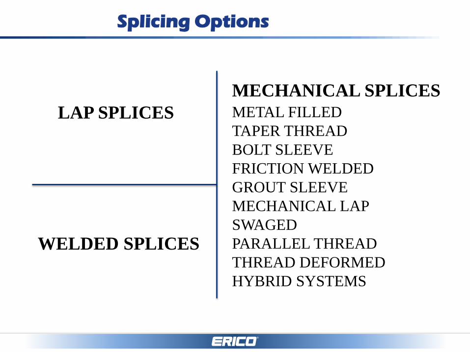
Splicing Options
LAP SPLICES
WELDED SPLICES
MECHANICAL SPLICES
METAL FILLED
TAPER THREAD
BOLT SLEEVE
FRICTION WELDED
GROUT SLEEVE
MECHANICAL LAP
SWAGED
PARALLEL THREAD
THREAD DEFORMED
HYBRID SYSTEMS
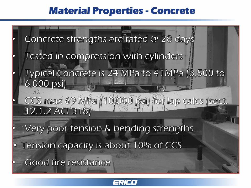
Material Properties - Concrete

Material Properties - Reinforcing Steel

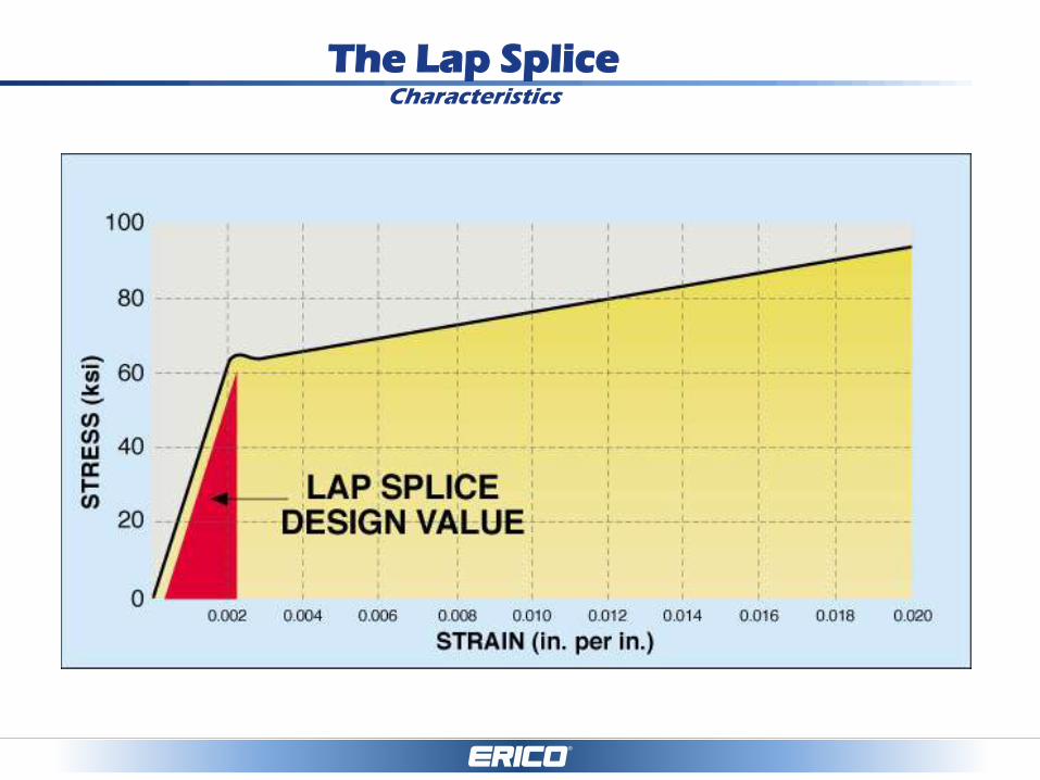
The Lap Splice Characteristics
• Only up to 36mm rebar – Can’t lap splice 38mm, 40mm,
43mm, 50mm & 57mm reinforcing steel
• Load is transferred by surrounding concrete
• Lap length dependent on grade of concrete
• Lap length dependent on the application
– ~50db
– longer for epoxy coated bars, top bars effects
• Lap length dependent on the diameter
• Negative for steel/concrete ratio
• Ductility not defined
• Placing and dimensioning risks
• Free end slip
• Low material cost
The Lap Splice Characteristics

What happens to a lap splice
when the concrete surrounding it
is gone?
Lap Splice Failure

Mechanical splices

Why Mechanical Splicing ?
• Improved Structural Integrity
• Eliminates Congestion Problems
• Consistent Steel to Concrete Ratio
• Safety & Formwork Considerations
• Eliminates Time-Consuming Calculations &
Detailing
• Material/Labor Cost Savings – Cagley study
0.2%
• Laps not allowed for bars larger than 36mm

Improved Structural Integrity
• Mechanical splices provide
independent load path continuity
regardless of condition of concrete.
• Lap splices depend on surrounding
concrete for strength.
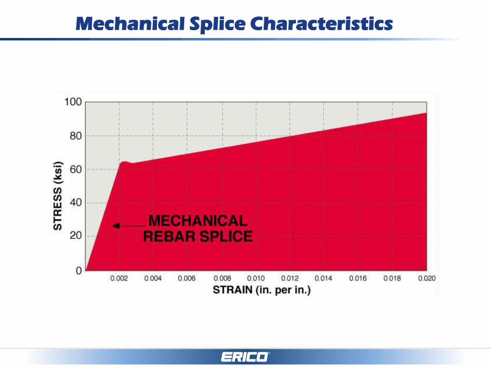
Mechanical Splice Characteristics

Congestion Problems
•Poor concrete
consolidation
•Rock Pockets
•Voids
•Steel to concrete ratio
issues
•Performance issues
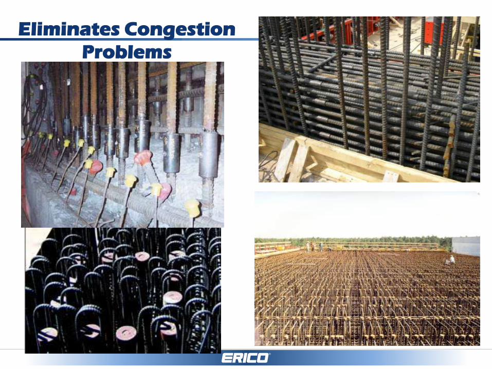
Eliminates Congestion
Problems
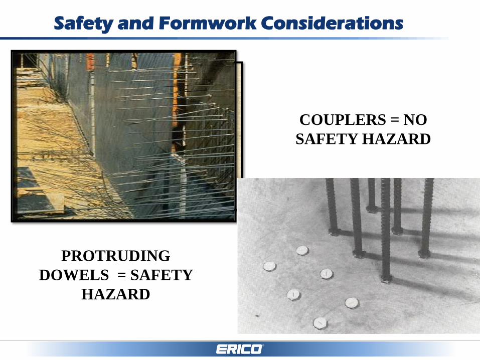
Safety and Formwork Considerations
COUPLERS = NO
SAFETY HAZARD
PROTRUDING
DOWELS = SAFETY
HAZARD
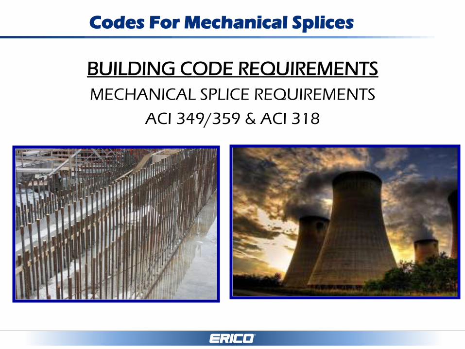
Codes For Mechanical Splices
BUILDING CODE REQUIREMENTS
MECHANICAL SPLICE REQUIREMENTS
ACI 349/359 & ACI 318

Codes For Mechanical Splices
ACI 318 – BUILDING CODE REQUIREMENTS (TYPE 1 & TYPE 2)
(TYPE 1) SECTION 12.14.3.2* – A FULL MECHANICAL SPLICE
SHALL DEVELOP IN TENSION OR COMPRESSION, AS REQUIRED,
AT LEAST 1.25 Fy OF THE BAR
(TYPE 2) SECTION 21.1.6.1(b)* – TYPE 2 MECHANICAL SPLICES
SHALL CONFORM TO 12.14.3.2* AND SHALL DEVELOP THE
SPECIFIED TENSILE STRENGTH OF THE BAR (SEISMIC)
*Section 25.5.7.1 & 18.2.7.1 in ACI 318-14
ACI Resource Center & Transition Keys: http://www.concrete.org/tools/318-
information/318-14-portal/318-14-faqs-and-sample-content.aspx

Codes For Mechanical Splices
Code Required Loads
REBAR TYPE SPEC. YIELD
Fy
TYPE 1 SPLICE
1.25*Fy
TYPE 2 SPLICE
1.0*Fu
ASTM A615
GRADE 60
60 ksi
(420MPa)
75 ksi
(520MPa)
90 ksi
(620MPa)
ASTM A615
GRADE 80
80 ksi
(550MPa)
100 ksi
(690MPa)
105 ksi
(725MPa)
ASTM A706
GRADE 60
60 ksi
(420MPa)
75 ksi
(520MPa)
80 ksi
(550MPa)
ASTM A706
GRADE 80
80 ksi
(550MPa)
100 ksi
(690MPa)
100 ksi
(690MPa)
NBR 7480
CA 50/CA 50S
500 Mpa
(72.5 ksi)
625 MPa
(90.6 ksi)
540 MPa
(78.3 ksi)

IBC AC133 Cyclic Test
-40,000
-20,000
0
20,000
40,000
60,000
80,000
100,000
-0.05 0.00 0.05 0.10 0.15 0.20 0.25 0.30 0.35 0.40 0.45
Lo
ad
(lb
s)
Elongation (in)
LENTON #8 SPLICE TEST - TH7432
COMPARISON
OF
SPLICE SYSTEMS
Splices allowed by ASME 359 & used in Nuclear
Containments per ACI
• Lap
• Ferrous Filler – CADWELD
• Taper Threaded – LENTON
• Welded
Mechanical Splices

Mechanical Splices
Types of splices allowed by ASME 359
• Lap
• Ferrous Filler – CADWELD
• Taper Threaded – LENTON
• Swaged
• Thread deformed Bar
• Sleeve with Grout – LENTON INTERLOK
• Cold roll or enlarged parallel thread
• Arc Weld
• *LENTON LOCK – set screw coupler added in 2010 addenda
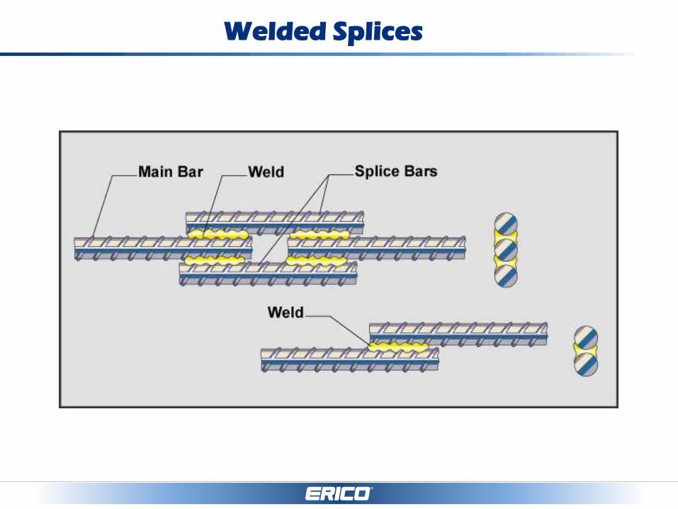
Welded Splices

Welded Splices
Advantages Disadvantages
• Low material cost
• ‘All’ connections
• Weldable steel
required
• Bulky ‘special’
equipment
• Skilled welders
required
• Expensive Quality
Control / Inspection
• Time consuming
• Size, congestion

Mechanical Splices
Swaged
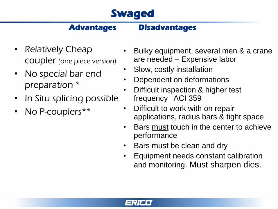
Swaged
Advantages Disadvantages
• Relatively Cheap
coupler (one piece version)
• No special bar end
preparation *
• In Situ splicing possible
• No P-couplers**
• Bulky equipment, several men & a crane are needed – Expensive labor
• Slow, costly installation
• Dependent on deformations
• Difficult inspection & higher test frequency ACI 359
• Difficult to work with on repair applications, radius bars & tight space
• Bars must touch in the center to achieve performance
• Bars must be clean and dry
• Equipment needs constant calibration and monitoring. Must sharpen dies.

LENTON Splicing and Headed Bar Options
Compression Only
Headed Bar/Anchorage
Tension And Compression
No Bar End Preparation
LENTON SPEED SLEEVE
LENTON TERMINATOR
LENTON
INTERLOK
LENTON
Coupler
LENTON
QUICK WEDGE LENTON LOCK
Taper-Threaded
LENTON
Position


Mechanical Splices
Tapered Threaded
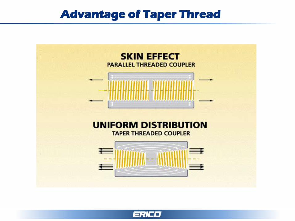
Advantage of Taper Thread

Tapered Threaded Splices
Advantages Disadvantages
• Fastest system to install
• Self aligning
• No cross threading
• Compact size
• Range of coupler types
• Easy to Inspect
• Full tensile strength
• Low slip
• Low installed cost
• Proven track record
• Needs Position type
coupler for bent bars
• Bar end threading

LENTON® Taper-threaded Splicing System
Rebar Sizes:
10mm – 57mm
Couplers Available:
Standard
Transition
Position
Weldable
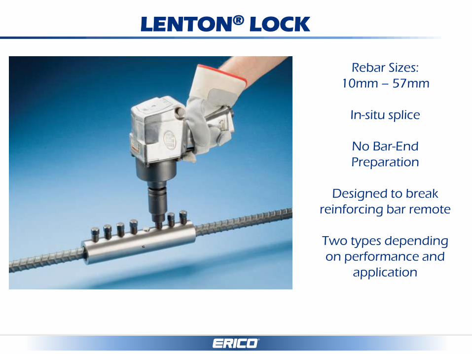
LENTON® LOCK
Rebar Sizes:
10mm – 57mm
In-situ splice
No Bar-End
Preparation
Designed to break
reinforcing bar remote
Two types depending
on performance and
application
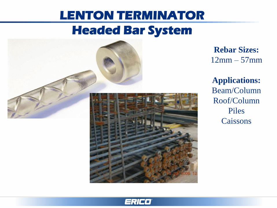
LENTON TERMINATOR
Headed Bar System
Rebar Sizes:
12mm – 57mm
Applications:
Beam/Column
Roof/Column
Piles
Caissons
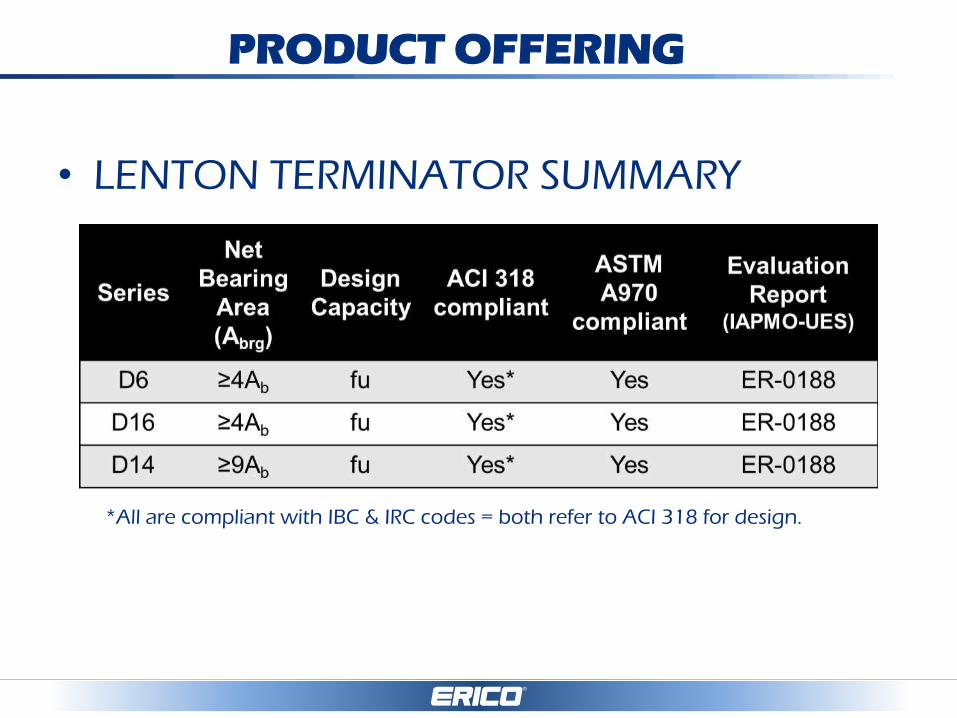
PRODUCT OFFERING
• LENTON TERMINATOR SUMMARY
*All are compliant with IBC & IRC codes = both refer to ACI 318 for design.

FEATURES and APPLICATIONS
• Eliminates/replaces hooks
• Shortens development lengths
• Reduces congestion problems
• Lightweight and normal weight concrete
• LENTON Taper Thread System
– Fast install
– Easy inspection
– Install/un-install/re-install capability
• Non-contact Lap Splice

Shear Cone Theory
LENTON TERMINATOR utilizes principles of the
Shear Cone Theory which effectively reduces the
development length of reinforcing bars.
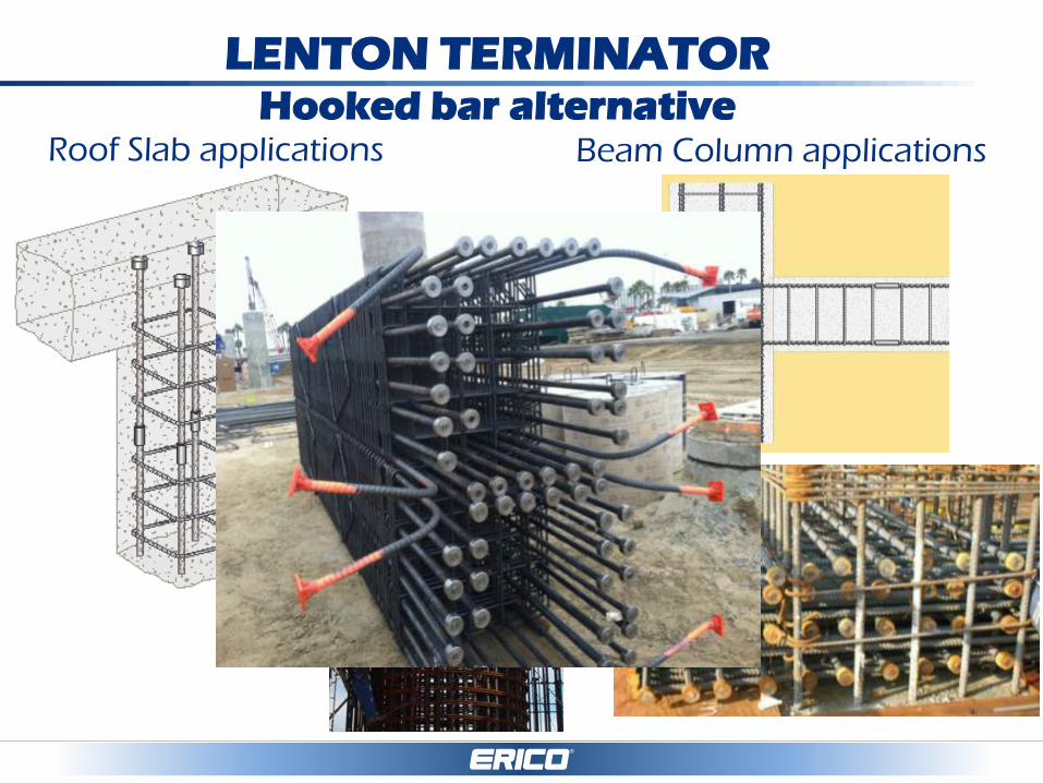
LENTON TERMINATOR Hooked bar alternative
Roof Slab applications Beam Column applications

CODES AND STANDARDS
• ACI 318
– Key Definitions
• Headed Deformed Bar – Deformed reinforcing bars with heads attached at one or both ends.
Heads are attached to the bar end by means such as welding or
forging on the bar, internal threads on the bar end, or a separate
threaded nut to secure the head of the bar. The net bearing area of a
headed deformed bar equals the gross area of the head minus the
larger of the area of the bar and the area of any obstruction. (Refer to ASTM A970 Section A1.1.1.5)
• Anchor – A steel element either cast into concrete or post-installed into a
hardened concrete member and used to transmit applied loads,
including headed bolts, hooked bolts (J- or L-bolt), headed studs,
expansion anchors, or undercut anchors.
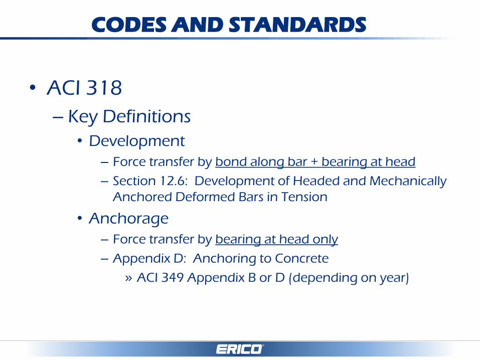
• ACI 318
– Key Definitions
• Development
– Force transfer by bond along bar + bearing at head
– Section 12.6: Development of Headed and Mechanically
Anchored Deformed Bars in Tension
• Anchorage
– Force transfer by bearing at head only
– Appendix D: Anchoring to Concrete
» ACI 349 Appendix B or D (depending on year)
CODES AND STANDARDS

CODES AND STANDARDS
• ACI 318
– Section 12.6 – Headed Deformed Bars
• Development length (ldh)
• Conditions of use (a) – (f)
• ASTM A970 compliant
– Appendix D - Anchors
• Anchorage length (hef)
• Any head size
• Anchor diameter limit
– ≤ 2” (ACI 318-08)…= 50mm, so includes 40,43,50mm!!
– ≤ 4” (ACI 318-11)…= 100mm, so includes 57mm!!!!
CODES AND STANDARDS
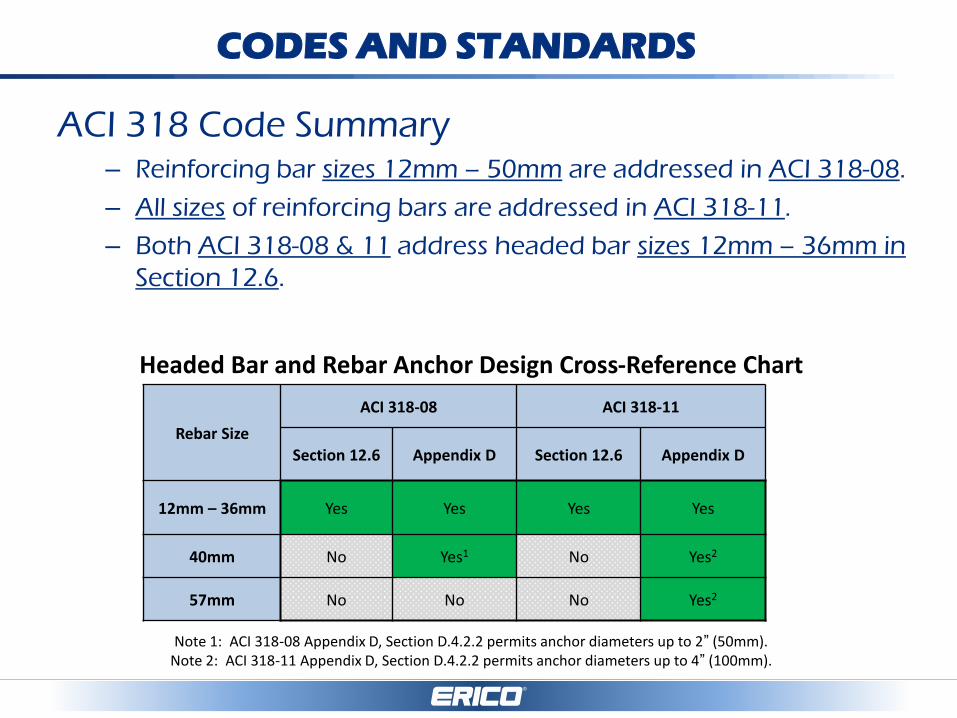
ACI 318 Code Summary
– Reinforcing bar sizes 12mm – 50mm are addressed in ACI 318-08.
– All sizes of reinforcing bars are addressed in ACI 318-11.
– Both ACI 318-08 & 11 address headed bar sizes 12mm – 36mm in
Section 12.6.
Headed Bar and Rebar Anchor Design Cross-Reference Chart
Note 1: ACI 318-08 Appendix D, Section D.4.2.2 permits anchor diameters up to 2” (50mm). Note 2: ACI 318-11 Appendix D, Section D.4.2.2 permits anchor diameters up to 4” (100mm).
Rebar Size
ACI 318-08 ACI 318-11
Section 12.6 Appendix D Section 12.6 Appendix D
12mm – 36mm Yes Yes Yes Yes
40mm No Yes1 No Yes2
57mm No No No Yes2
CODES AND STANDARDS
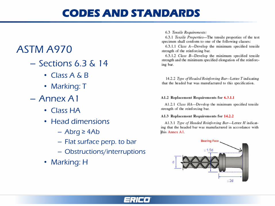
ASTM A970
– Sections 6.3 & 14
• Class A & B
• Marking: T
– Annex A1
• Class HA
• Head dimensions
– Abrg ≥ 4Ab
– Flat surface perp. to bar
– Obstructions/interruptions
• Marking: H
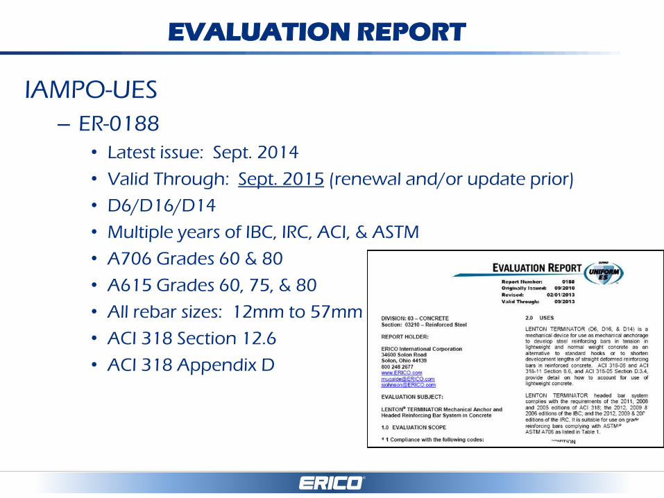
EVALUATION REPORT
IAMPO-UES
– ER-0188
• Latest issue: Sept. 2014
• Valid Through: Sept. 2015 (renewal and/or update prior)
• D6/D16/D14
• Multiple years of IBC, IRC, ACI, & ASTM
• A706 Grades 60 & 80
• A615 Grades 60, 75, & 80
• All rebar sizes: 12mm to 57mm
• ACI 318 Section 12.6
• ACI 318 Appendix D
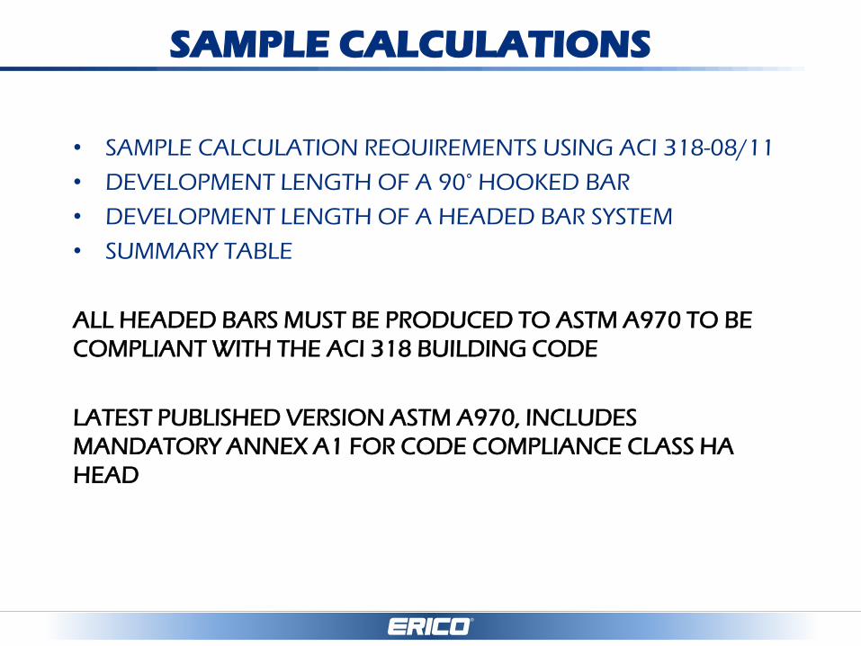
SAMPLE CALCULATIONS
• SAMPLE CALCULATION REQUIREMENTS USING ACI 318-08/11
• DEVELOPMENT LENGTH OF A 90° HOOKED BAR
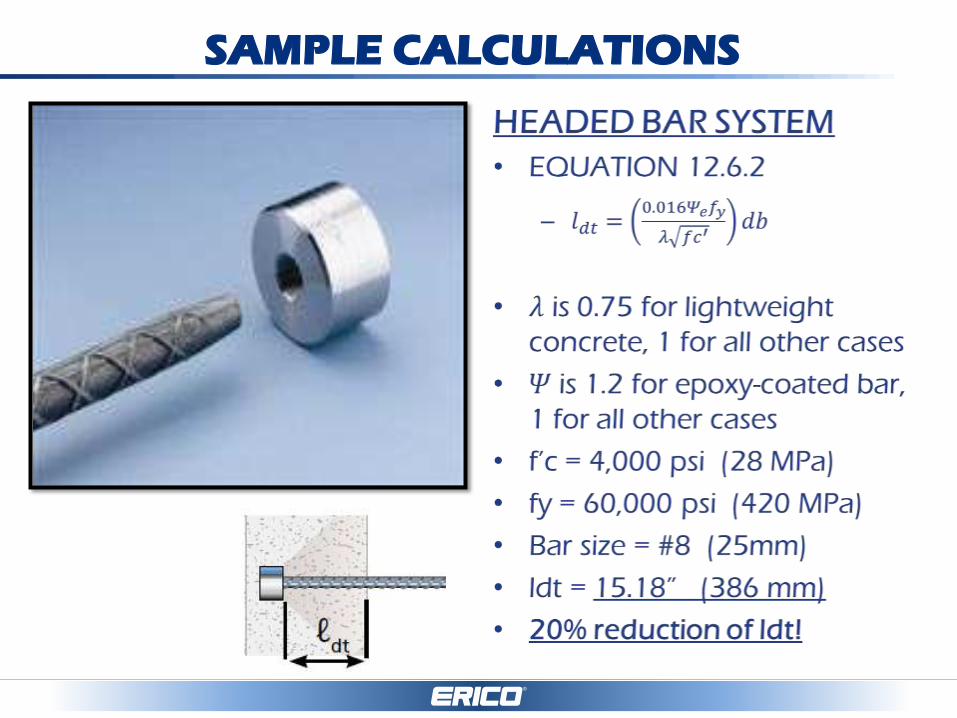
• DEVELOPMENT LENGTH OF A HEADED BAR SYSTEM
• SUMMARY TABLE
ALL HEADED BARS MUST BE PRODUCED TO ASTM A970 TO BE
COMPLIANT WITH THE ACI 318 BUILDING CODE
LATEST PUBLISHED VERSION ASTM A970, INCLUDES
MANDATORY ANNEX A1 FOR CODE COMPLIANCE CLASS HA
HEAD

SAMPLE CALCULATIONS
DESIGN ASSUMPTIONS/PARAMETERS
SECTION 12.5* OF ACI 318 (90°HOOKED BARS)
SECTION 12.6* OF ACI 318 (HEADED BARS)
CONCRETE STRENGTH = 4,000 PSI (28 MPa)
25mm ASTM A615 GRADE 60 REBAR
*Section 25.4.3 & 25.4.4 in ACI 318-14
ACI Resource Center & Transition Keys: http://www.concrete.org/tools/318-information/318-14-portal/318-14-faqs-and-sample-content.aspx

SAMPLE CALCULATIONS
CONDITIONS OF USE FOR EQ. 12.6.2
• BAR fy SHALL NOT EXCEED 60,000 PSI (420 MPa)
• BAR SIZE SHALL NOT EXCEED #11 (36 mm)
• CONCRETE SHALL BE NORMALWEIGHT, ≥ 6,000 PSI (41MPa)
• NET BEARING AREA OF HEAD (Abrg) SHALL NOT BE LESS THAN 4Ab
• CLEAR COVER FOR BAR SHALL NOT BE LESS THAN 2db
• CLEAR SPACING BETWEEN BARS SHALL NOT BE LESS THAN 4db (changed to 3db in ACI 318-14)
** IF THESE CONDITIONS ARE NOT MET DESIGN OF MECHANICAL ANCHORS FALL UNDER APPENDIX D OR ACI 352

SAMPLE CALCULATIONS
SAMPLE CALCULATIONS
SAMPLE CALCULATIONS
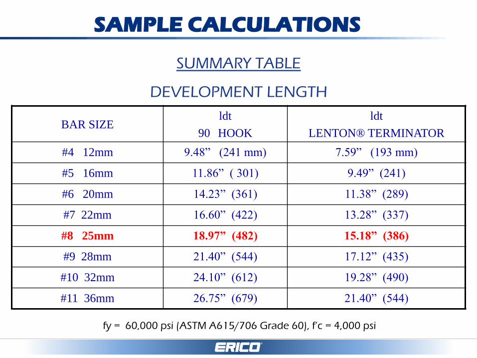
SUMMARY TABLE
DEVELOPMENT LENGTH
BAR SIZE ldt
90 HOOK
ldt
LENTON® TERMINATOR
#4 12mm 9.48” (241 mm) 7.59” (193 mm)
#5 16mm 11.86” ( 301) 9.49” (241)
#6 20mm 14.23” (361) 11.38” (289)
#7 22mm 16.60” (422) 13.28” (337)
#8 25mm 18.97” (482) 15.18” (386)
#9 28mm 21.40” (544) 17.12” (435)
#10 32mm 24.10” (612) 19.28” (490)
#11 36mm 26.75” (679) 21.40” (544)
fy = 60,000 psi (ASTM A615/706 Grade 60), f’c = 4,000 psi
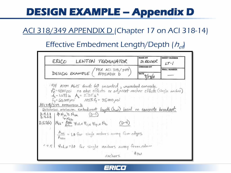
DESIGN EXAMPLE – Appendix D
ACI 318/349 APPENDIX D (Chapter 17 on ACI 318-14)
Effective Embedment Length/Depth (hef)
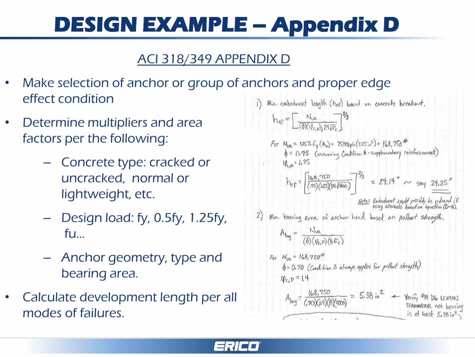
DESIGN EXAMPLE – Appendix D
ACI 318/349 APPENDIX D
• Make selection of anchor or group of anchors and proper edge
effect condition
• Determine multipliers and area
factors per the following:
– Concrete type: cracked or
uncracked, normal or
lightweight, etc.
– Design load: fy, 0.5fy, 1.25fy,
fu…
– Anchor geometry, type and
bearing area.
• Calculate development length per all
modes of failures.

DESIGN EXAMPLE – Appendix D
• Now, Let’s try an example with a 25mm bar and 500 MPa reinforcing for
concrete breakout mode of failure
DESIGN EXAMPLE – Appendix D
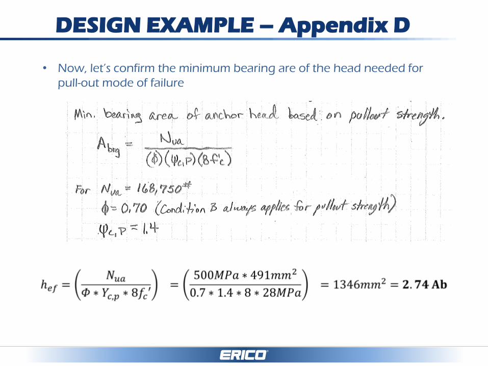
• Now, let’s confirm the minimum bearing are of the head needed for
pull-out mode of failure

TESTS PROTOCOLS & PERFORMANCE
• ICC/ICBO & IAPMO – AC 347 (Seismic Protocol)
– Type 2
– Class HA
• DiBT (Germany) – LENTON TERMINATOR D14
– <0.1mm slip at 0.6fy (325 MPa)
– 95% tensile efficiency
– Fatigue 2MM cycles at 60 MPa band
• AFCAB (France) – LENTON TERMINATOR D14
– <0.1mm slip at 0.6fy (325 Mpa)
– 95% tensile efficiency
• CALTRANS – LENTON TERMINATOR D16/D14
– ASTM A706 grade 60 min specified tensile stress (550 MPa)
– 100 cycles – 0.05fy to 0.9fy
UNIVERSITY RESEARCH
• Wallace Report
• Keith Thompson Papers
• Purdue testing
• Kansas University shear reinforcement and high
strength steel research

FAQ’s
Refer to separate pdf document…convenient
reference tool for design and use of headed bars….

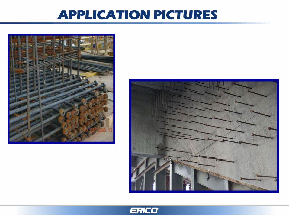
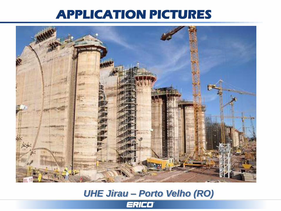
APPLICATION PICTURES
CAGING APPLICATIONS
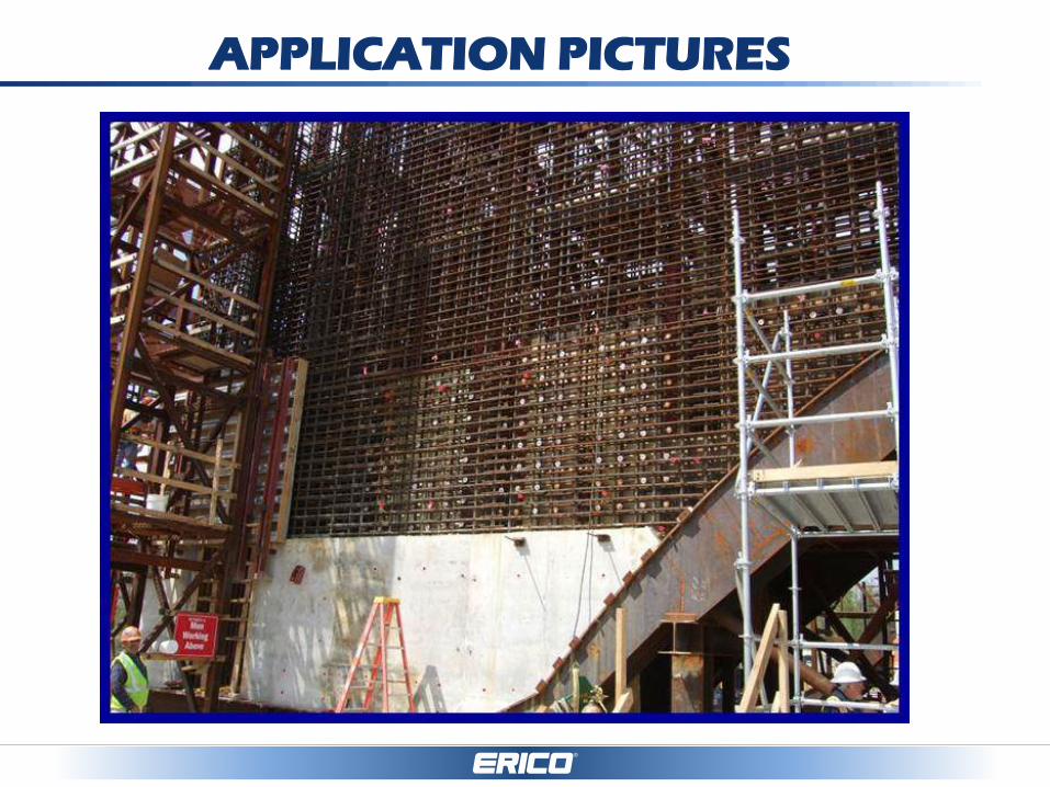
APPLICATION PICTURES
APPLICATION PICTURES

SAN JOSE REGIONAL MEDICAL CENTER, CALIFORNIA
APPLICATION PICTURES

APPLICATION PICTURES

APPLICATION PICTURES
Monotrilho Linha 15 – São Paulo (SP)
APPLICATION PICTURES
UHE Jirau – Porto Velho (RO)

Brookfield Towers – São Paulo (SP)
APPLICATION PICTURES

Brookfield Towers – São Paulo (SP)
APPLICATION PICTURES
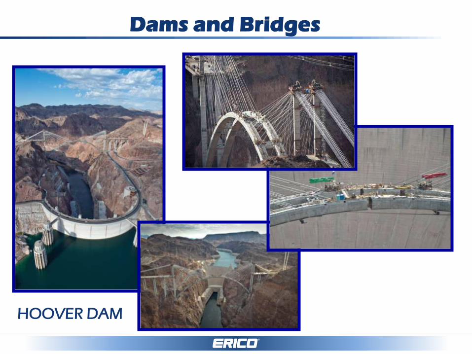
Dams and Bridges
HOOVER DAM
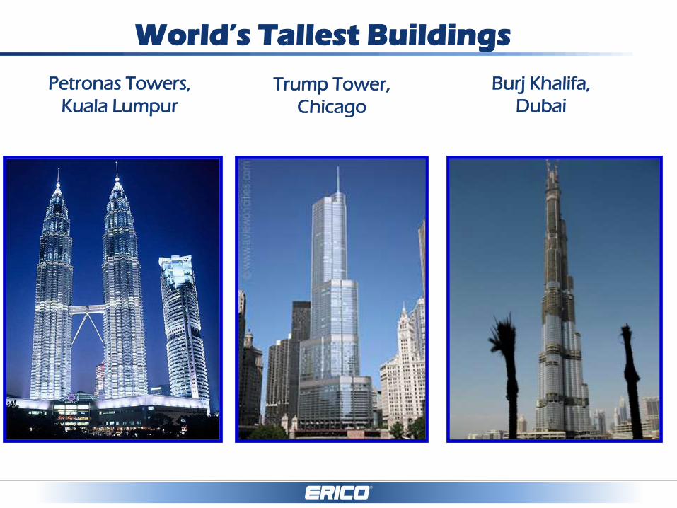
World’s Tallest Buildings
Petronas Towers,
Kuala Lumpur
Trump Tower,
Chicago
Burj Khalifa,
Dubai
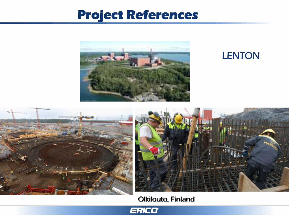
Project References
Olkilouto, Finland
LENTON
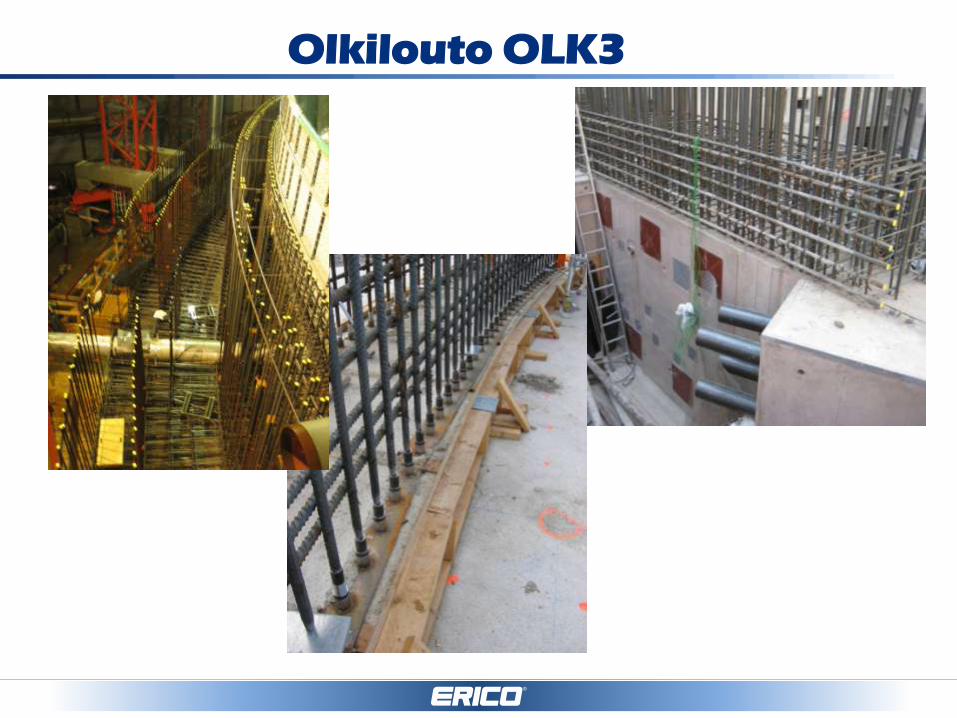
Olkilouto OLK3

Vogtle & VC Summer
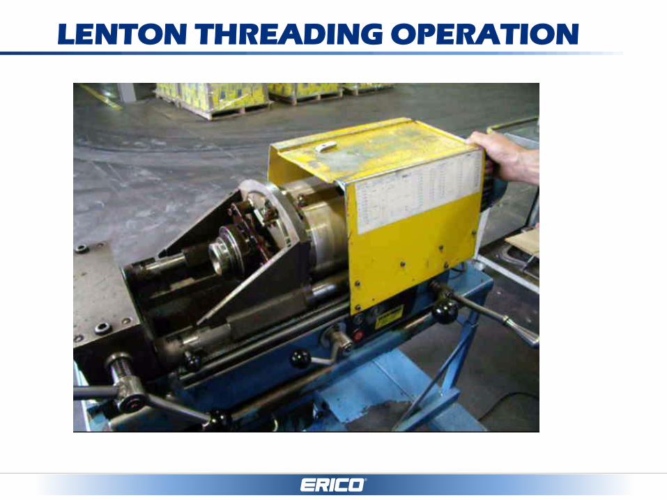
LENTON THREADING OPERATION
Thank you
Pentair Engineered Electrical &
Fastening Solutions
New Product Platforms

Purpose of this discussion is to
introduce LENTON's strategy for
future offerings and get feedback
from you.
Today’s Discussion
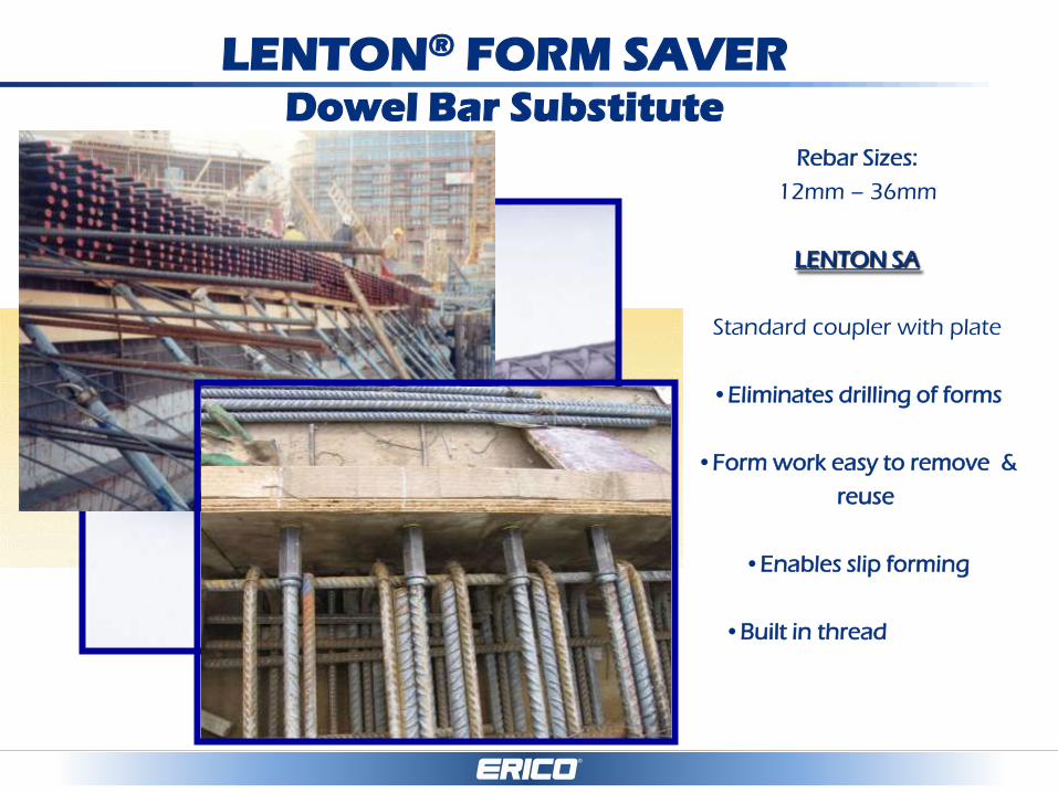
LENTON® FORM SAVER Dowel Bar Substitute
Rebar Sizes:
12mm – 36mm
LENTON SA
Standard coupler with plate
•Eliminates drilling of forms
•Form work easy to remove &
reuse
•Enables slip forming
•Built in thread protector
•Eliminates bend / re-bend of bar
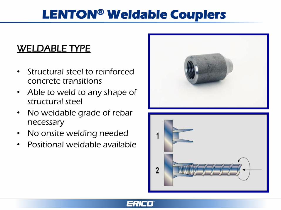
LENTON® Weldable Couplers
WELDABLE TYPE
• Structural steel to reinforced concrete transitions
• Able to weld to any shape of structural steel
• No weldable grade of rebar necessary
• No onsite welding needed
• Positional weldable available
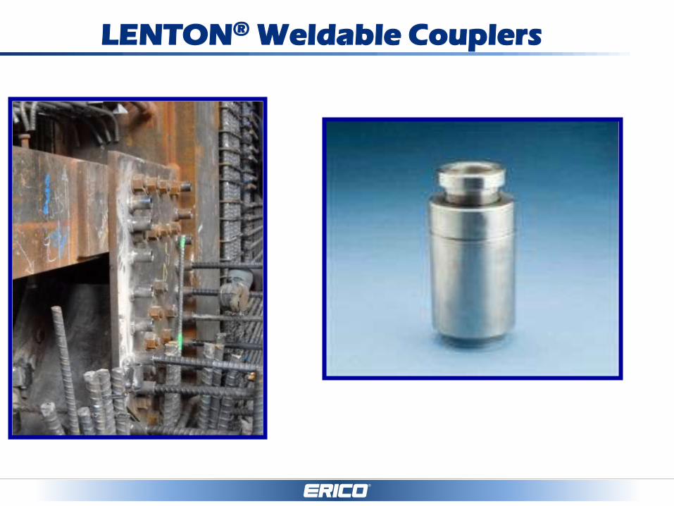
LENTON® Weldable Couplers
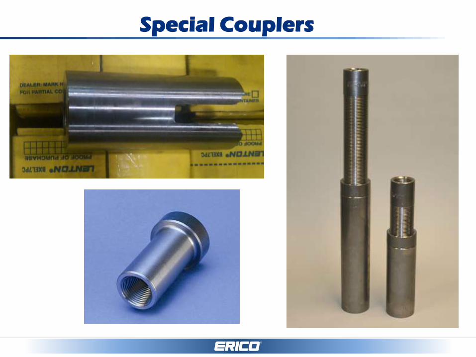
Special Couplers
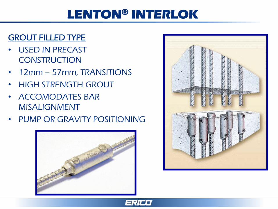
LENTON® INTERLOK
GROUT FILLED TYPE
• USED IN PRECAST
CONSTRUCTION
• 12mm – 57mm, TRANSITIONS
• HIGH STRENGTH GROUT
• ACCOMODATES BAR
MISALIGNMENT
• PUMP OR GRAVITY POSITIONING

LENTON® QUICK WEDGE
MECHANICAL LAP TYPE
• 10mm – 20mm
• RETROFIT WORK
• MIN. EXPOSED DOWEL
LENGTHS
• VISUAL INSPECTION

– LLM with D14, D16, C14 &
PC14
– Finalizing design phase
– Domestic and non-domestic
– 12mm, 16mm, 20mm, 22mm,
25mm, 28mm, 32mm & 36mm
– Performance as current
LENTON LOCK B-series
– Witnessed test data will be
available
– Est. completion date: 2016
LENTON LOCK MODULAR

Market Influencing Factors
• Performance and Codes
• Commercial Factors
• Costs
• Constructability

• Performance and Codes
• Commercial Factors
• Costs
• Constructability
Market Influencing Factors

Worldwide Performance
Categories Performance Category Coverage - Examples
LAP Non Mechanical Splices and Anchors
Basic Mechanical ACI 318 Type 1, 125% fy, 540 MPa, CANCSA, AS3600, 108%fy, non seismic demands
Intermediate Mechanical ACI Type 2, Min Fuk , DIN 1045, BS 8110, ISO 15835 S1/S2 low cycle fatigue, 0.1mm slip, AC 133, <95% fy, Service Splice, UK Cares TA1B, NFA-35-020-1, ASME III div 2, ACI 349. 60 MPa High cycle fatigue. Agt < 5%
Superior Mechanical High end and unique project needs or specifications that might include Bar Break remote, high Strain Agt ≥ 5%, high cycle fatigue, UK Cares TA1C & D Class fatigue, blast, nuclear, ultimate splice, NZ3101, JGJ, JIS, Ultra-high strength rebar.
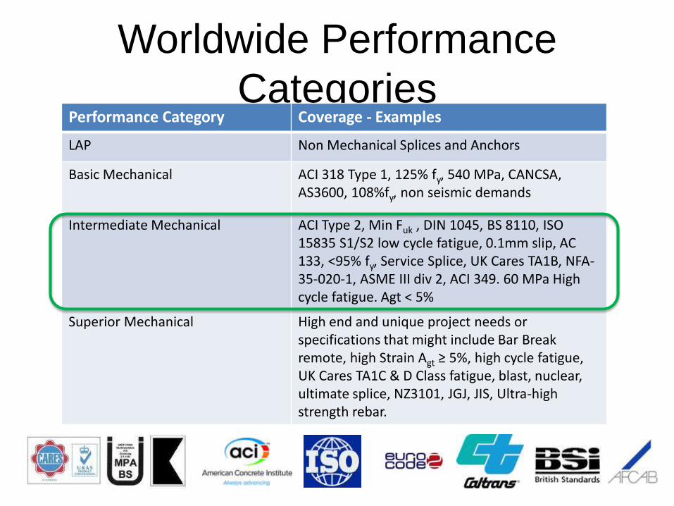

Strategic Expansion Performance Category
LAP
Basic Mechanical
Intermediate Mechanical
Superior Mechanical
Evaluation Criteria:
Performance & Codes Commercial Factors Installed Costs Constructability

Feedback From You
We would appreciate any comments or
suggestions to help us develop a product
that satisfies your needs.
As world-wide leader in reinforcing bar
splices, LENTON® is able to :
• Always offer the optimum technical solution
• Make a selection with you from our broad
product range that fits your project and
application
• Offer you the maximum advantages of
mechanical reinforcing bar splices
• Support your projects as a reliable logistic and
technical partner

Why use LENTON Mechanical Splice?
• Minimize Your Risk
– Array of products to meet the applications
– Meet the requirements
– Have Capacity
– Have the Quality systems in Place – NQA1
– Have the Expertise and Experience
– Have the Partnerships
– Make custom components to meet unique project
needs.

Thank you
Pentair Engineered Electrical &
Fastening Solutions
QUESTIONS ?
AFFILIATIONS

Testing at Purdue University