PENTAGON RENOVATION WEDGE 3 Arlington, VA Report.pdf · PENTAGON RENOVATION WEDGE 3 Arlington, VA...
82
PENTAGON RENOVATION WEDGE 3 Arlington, VA Julie Rankin Construction Management Advisor Dr. David Riley The Pennsylvania State University Architectural Engineering Senior Thesis
Transcript of PENTAGON RENOVATION WEDGE 3 Arlington, VA Report.pdf · PENTAGON RENOVATION WEDGE 3 Arlington, VA...

PENTAGON RENOVATION WEDGE 3
Arlington, VA
Julie Rankin Construction Management
Advisor Dr. David Riley
The Pennsylvania State University Architectural Engineering Senior Thesis

Pentagon-Wedge 3 Renovation Jefferson Davis Highway
Arlington, VA
Julie Rankin Construction Management
http://www.arche.psu.edu/thesis/eportfolio/current/portfolios/jlr380/
GENERAL PROJECT INFORMATION • Type: Demolition and Renovation • Building Purpose: Office space / US department of defense operations • Estimated cost: $367 million • Contract: Design Build, fast track • Start Date: June, 2005 • Finish Date: February 2, 2007 • LEED accredited: Silver Rating
PRIMARY PROJECT TEAM • Owner: PenRen—Pentagon Renovation • General Contractor: Hensel Phelps Construction Co. • Architect: Shalom Baranes Associates • Mechanical and Plumbing: Southland Industries • Electrical: M.C. Dean • Demolition: LVI • Carpentry: P&P Contractors • Masonry: Masonry ARts
ARCHITECTURE • Unique five sided geometry with five concentric rings • Approximately 1 million square feet—Wedge 3 • Five stories above grade, 77 feet tall • Each side 921 feet long • Universal Space Plan—open environment
STRUCTURAL SYSTEM • Existing Building built in 1941 • CIP Concrete Columns • CIP Concrete girders and beams—span 20’ to 40’ • One-way Concrete Slabs—5” to 10” thickness • Columns doubled at expansion joints
LIGHTING / ELECTRICAL • Highly efficient fluorescent lighting • High CCT—natural light look • Utilizes daylight for 15% energy savings • Telecommunication closets disperse local data
and communication wiring in 4” conduit and overhead cable trays
MECHANICAL • Air is conditioned off site from Wedge 3 • Overhead round duct delivery / no return ducts • Induction units

Advisor: Dr. Riley Julie Rankin i. 1 Construction Management
Pentagon Renovation Arlington, VAWedge 3
Executive Summary This report summarizes a year’s worth of research of the Pentagon Renovation
Wedge 3. The project background section provides details about the buildings history,
architecture and the current construction project. Pentagon 101 is a brief tutorial to
orient a stranger with the layout of Wedge 3.
The three analyses that were performed involved construction management and
other breadth research topics.
A green roof system was designed to place on the roof of the Pentagon,
including a structural breadth with loading calculations. It also explores the extensive
type of roofing required and the growth mediums ideal for the climate in Arlington, VA.
This requires durable plants that withstand drought, saturation and both hot and cold
temperature.
A second topic evaluates placing a raised access floor in a large portion of the
office and control room spaces. In addition, a mechanical breadth explores the existing
air circulation patterns and suggest an improvement by placing the return and supply air
in different locations.
A third evaluation looks at the demolition plan and proposes an alternative way
to remove debris during the summer demolition process.
Brief Table of Contents Project Background…………………………………………………………………………………………………ii
Pentagon 101………………………………………………………………………………………………………..iii
Green Roof……………………………………………………………………………………………………………1
Structural Breadth
Access Floor………………………………………………………………………………………………………….2
Mechanical Breadth
Demolition Plan……………………………………………………………………………………………………..3
Project Teams Research……………….…………………………………………………………………………4
Acknowledgements

Advisor: Dr. Riley Julie Rankin ii. 1 Construction Management
Pentagon Renovation Arlington, VAWedge 3
Project Background
Building History..................................................................... ii.2 Client Information.................................................................. ii.3
Cost.............................................................................................. ii.4 Quality .......................................................................................... ii.4 Schedule ...................................................................................... ii.5 Safety ........................................................................................... ii.6 Occupancy ................................................................................... ii.6
Project Delivery System........................................................ ii.7
Advisor: Dr. Riley Julie Rankin ii. 2 Construction Management
Pentagon Renovation Arlington, VAWedge 3
Building History
The well-known Pentagon structure owes much of its appearance to the political
and social climate during the time of its construction. It was built during World War II,
and in an effort to not exhaust the supply of metals needed for war machines, the
structure was designed as fully cast in place poured concrete. The only structural steel
originally found in the Pentagon was reinforcement in the concrete. Now in the
renovated area, there are steel reinforcing beams to support penetrations cut for utility
risers and people moving systems.
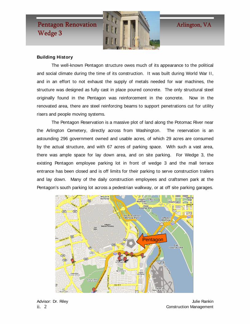
The Pentagon Reservation is a massive plot of land along the Potomac River near
the Arlington Cemetery, directly across from Washington. The reservation is an
astounding 296 government owned and usable acres, of which 29 acres are consumed
by the actual structure, and with 67 acres of parking space. With such a vast area,
there was ample space for lay down area, and on site parking. For Wedge 3, the
existing Pentagon employee parking lot in front of wedge 3 and the mall terrace
entrance has been closed and is off limits for their parking to serve construction trailers
and lay down. Many of the daily construction employees and craftsmen park at the
Pentagon’s south parking lot across a pedestrian walkway, or at off site parking garages.
Pentagon

Advisor: Dr. Riley Julie Rankin ii. 3 Construction Management
Pentagon Renovation Arlington, VAWedge 3
The land where the Pentagon was built was originally a swampy marshland on
the banks of the Potomac River. Though drained, it is susceptible to soggy ground
conditions. The foundation of the original concrete structure has settled, and the
ground below it has compressed, unevenly at times, over the years under the immense
weight of the building, but the structure is still sound.
As this building renovation project strives for LEED certification, it naturally
involves recycling in the construction process. Old materials are sorted and recycled
after their demolition, and new materials for the rebuilding are recycled as well. The
Pentagon reservation also is located near an alternative fuel station with higher
efficiency fuel, which helps to, giving another credit to the building for LEED
certification.
Client Information
The owner of the project is a government program known as
the Pentagon Renovation Program, commonly referred to as PenRen.
Wedge 3 is only one part of a large renovation plan to rebuild the
entire reservation, including not only the immediate structure, but
also a new metro entrance, and a remote deliveries facility. PenRen
was formed out of necessity to have a team of people leading the
renovation project.
This construction project is crucial because the building is now nearly sixty four
years old, and many of its’ major systems have yet to be updated. Tenants have
repeatedly enclosed areas for personal office space, reducing efficiency for flow of the
old air supply. Old pipes suffer from leaks, rust and corrosion. Asbestos materials were
common in construction in the 1940’s, and over 23 million pounds of asbestos material
are found throughout the Pentagon, including floor and ceiling tiles and various
insulation. PCB’s were visible in the ballasts of lighting systems and lead paints still coat
much of the space. In total, the building’s systems were outdated, inefficient,
hazardous, and ironically often times failing building codes. In recognition of this,
Advisor: Dr. Riley Julie Rankin ii. 4 Construction Management
Pentagon Renovation Arlington, VAWedge 3
PenRen initially developed guidelines and standards, for quality, cost and safety.
One of the prominent goals of PenRen was to achieve an economical, aesthetic,
and most importantly uniform new look for the Pentagon. Another expectation was that
the updates would last for at least fifty years before another major renovation was
necessary, prompting them to set the specifications in construction contracts for a fifty
year design.
Cost
The major cost concern that PenRen had during the developmental stages of
Wedges 2 through 5 was keeping the project on the predetermined budget. Wedge 3 is
comprised mostly of office space, with repetitive systems and floor plans. Therefore, if
a part of the design specified equipment of material that was less cost efficient than an
alternative, the price is multiplied throughout the entire floor plan, making the costs for
inefficiency substantial. To avoid this, the architect, general contractor and PenRen
worked closely through the design process, creating mock ups in an attempt to alleviate
issues during construction.
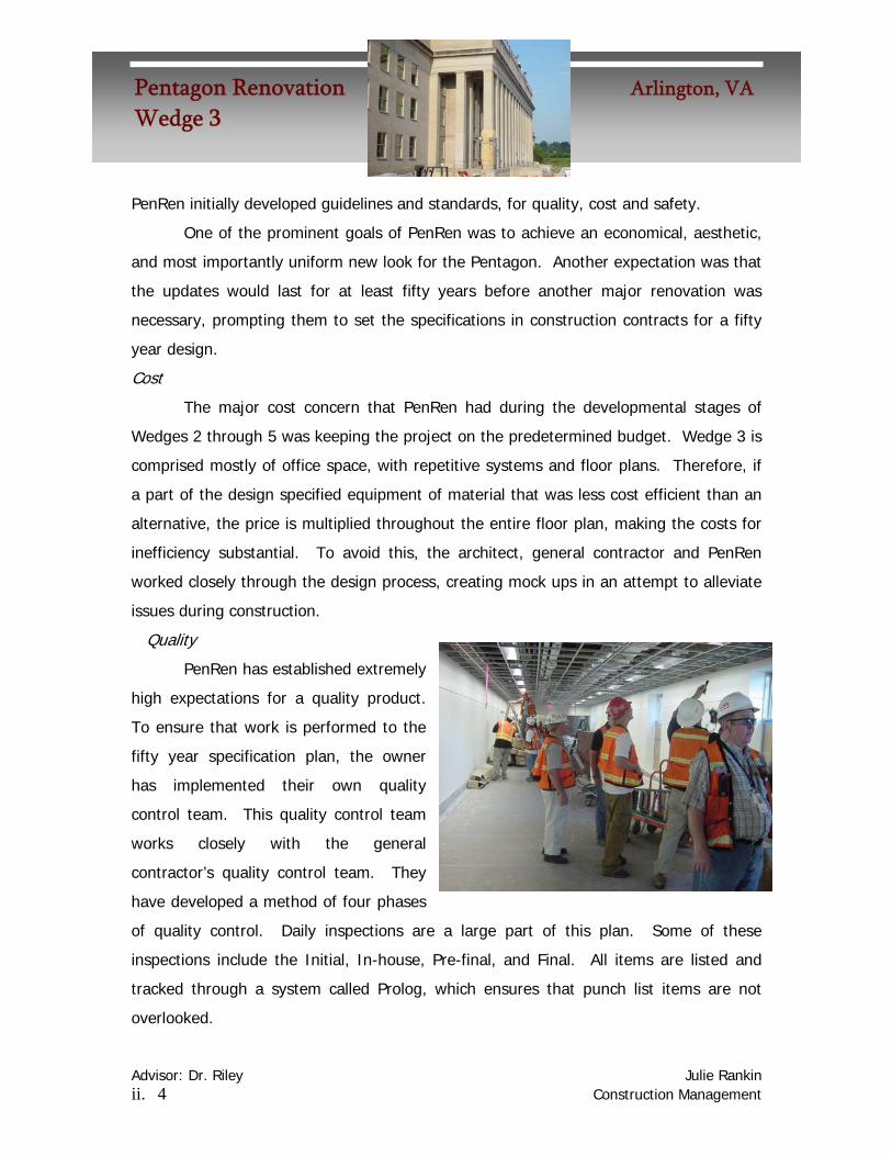
Quality
PenRen has established extremely
high expectations for a quality product.
To ensure that work is performed to the
fifty year specification plan, the owner
has implemented their own quality
control team. This quality control team
works closely with the general
contractor’s quality control team. They
have developed a method of four phases
of quality control. Daily inspections are a large part of this plan. Some of these
inspections include the Initial, In-house, Pre-final, and Final. All items are listed and
tracked through a system called Prolog, which ensures that punch list items are not
overlooked.

Advisor: Dr. Riley Julie Rankin ii. 5 Construction Management
Pentagon Renovation Arlington, VAWedge 3
A system of tagging is used during inspections. The tags are color coded, so
that various subcontractors recognize the tags hanging from objects and identify the
color as their own to know if they are involved in addressing the issue. The color coding
works as follows:
• Blue – Drywall / Carpentry
• Red – Mechanical
• Green – Electrical
• Orange – Caulk
• Purple – Other / Miscellaneous
All tagged items are entered into prolog
by the QC administrators and `tracked daily
by PenRen and Hensel Phelps inspectors.
Schedule
When dealing with a renovation project of such magnitude, schedule is
inherently a critical issue. Wedge 3 is only one wedge of five at the Pentagon, and with
each one having a size of approximately one million square feet, it was important to the
owner that each wedge was completed quickly, or else the space would be losing a lot
of potential office space, and hence efficiency of its operations.
Initially, the entire Pentagon Master Plan Renovation was projected to be
complete in 2014, with the finishing of the fifth wedge. This placed Wedge 3 at a
completion date of 2009 or 2010. However, combining some unique acceleration ideas
and SIPS, or short interval production schedules, the general contractor was able to
develop a fast track schedule that calls for completion of the fifth wedge by 2010,
setting Wedge 3 for full completion in 2007. This is one of the reasons that PenRen
chose Hensel Phelps as the major general contractor for Wedges 2 through 5. The first
phase of Wedge 3 will turn over to the owner in January of 2007, while the second
phase will be turned over in October of the same year.

Advisor: Dr. Riley Julie Rankin ii. 6 Construction Management
Pentagon Renovation Arlington, VAWedge 3
Safety
The owner, in conjunction with the general contractors, has set an extremely
high standard for safety on the construction site. A major concern is keeping civilians
and military personnel away from construction. The solution is to fully isolate all
construction areas. Only individuals with a proper construction badge may enter the site
at any time, and under no circumstances may escorted visitors enter. Properly trained
Pentagon Police officers patrol the site daily to enforce this regulation.
Another example of the safety standard is the barrier wall. A metal framed, fire
rated wall must separate usable Pentagon space from the construction zone. All
penetrations must be caulked and fireproofed, leaving no gaps. Metal doors are
installed for fire escape purposes, but they have plentiful signage discouraging any non-
construction traffic.
It is necessary for anyone who is given a construction badge to undergo a safety
training seminar, lead by a safety expert from the general contractor, Hensel Phelps.
The class is offered in both English and Spanish, and is an approximately four hour
session reviewing
A final example of the safety precautions is the enforcement of PPE, or personal
protective equipment. Any individual entering the site must wear three articles of PPE,
which are hardhat, a brightly colored construction vest, and safety glasses. The hardhat
must face forward, and the safety glasses must not be darkly shaded or worn over
glasses unless they are the proper design for that purpose.
Occupancy
Over 23,000 people work at the Pentagon everyday, some military and others
civilians and civil servants. While this is not considered any where near the full capacity
of the building, it is still a major concern of the owner that daily operations not be
disturbed or productivity decreased as a result of the construction. Though tenants
must be relocated during renovation, PenRen desires that the tenants are
Advisor: Dr. Riley Julie Rankin ii. 7 Construction Management
Pentagon Renovation Arlington, VAWedge 3
accommodated. Tenants are notified months ahead of time as to the date that they will
need to move their offices.
It is also important to the owner that each division of the military operating
inside the Pentagon has the opportunity to be involved in the design phase of their new
area. Involvement in the tenant fit out process ensures that the office spaces are
comfortable and have efficiencies not possible in the section not yet renovated.
Project Delivery System
The Pentagon Wedge 3 is a contract that is separate from all other wedges’
contracts. It is a design build project, with a fast track delivery. This was initially used
for Wedge 2 construction and was successful, and will most likely be implemented
throughout the remainder of the Pentagon Renovation.
The owner, PenRen, has a lump sum contract with the main general contractor,
Hensel Phelps, who in turn has lump sum contracts with each of its’ subcontractors. It
is written into the contract between PenRen and Hensel Phelps that if the work is not
completed on time and to the expected specifications, the general contractor must cover
the cost. Also, the general contractor is reviewed on a quarterly basis and is eligible for
bonuses depending on how their work is being performed.
The following organizational chart makes visible the contractual bonds between
the owner, the general contractor and architect, and the subcontractors involved.

Advisor: Dr. Riley Julie Rankin ii. 8 Construction Management
Pentagon Renovation Arlington, VAWedge 3
Project Delivery System – Primary ContractorsDesign BuildFast Track
OwnerPentagon Renovation
General ContractorHensel Phelps
Construction Co.
Shalom BaranesAnd Associates
Architect
Other GC’sFederal Security
Systems
Other GC’sGeneral
Dynamics
P&PCarpentry
Southland IndustriesMechanical/
Plumbing
M.C. DeanElectrical
LVIDemolition
Roman MosaicTerrazzo
ChesapeakeFireproofing
Masonry ArtsMasons
SterlingSpecial Abatement
Air ServicesSpecial Abatement
Lump SumContract
Lump SumContracts
Coordination / Scheduling

Advisor: Dr. Riley Julie Rankin iii. 1 Construction Management
Pentagon Renovation Arlington, VAWedge 3
Pentagon 101
This section was added to rid some of the confusion about the Pentagon.
Through this report, various regions will be referred to and this tutorial will help one
understand the areas being discussed.
The Pentagon is organized into ten bays, and for the purpose of construction
was divided into five wedges. Since September the 11th, a common question is, “Where
exactly did the plane contact the building?” This occurred in what is called Wedge 1,
and is shown below.
Advisor: Dr. Riley Julie Rankin iii. 2 Construction Management
Pentagon Renovation Arlington, VAWedge 3
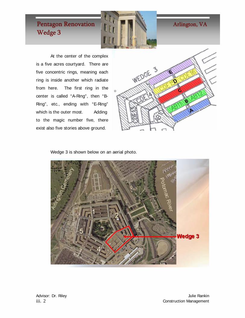
At the center of the complex
is a five acres courtyard. There are
five concentric rings, meaning each
ring is inside another which radiate
from here. The first ring in the
center is called “A-Ring”, then “B-
Ring”, etc., ending with “E-Ring”
which is the outer most. Adding
to the magic number five, there
exist also five stories above ground.
Wedge 3 is shown below on an aerial photo.

Advisor: Dr. Riley Julie Rankin iii. 3 Construction Management
Pentagon Renovation Arlington, VAWedge 3
The construction plan separates Wedge 3, into two phases, shown below. The
construction scope of Wedge 3 includes all five above ground levels and all five rings.
Corridors seven and eight will
be discussed throughout the
report, Corridor seven is along
the left side of phase I, will
Corridor 8 is between Phase I
and Phase II.
The ten bays are shown to
the right, labeled “bays 100”,
“bays 200”, etc, until the last
“bay 1000”. Wedge 3
belongs to the 700, 800 and
a section of the 900 bays.
Now, the reader should be
generally oriented to the
regions discussed.

Advisor: Dr. Riley Julie Rankin 1. 1 Construction Management
Pentagon Renovation Arlington, VAWedge 3
Analysis 1 Table of Contents
Introduction ...........................................................................1.2 Environmental Problems
Heat Island ................................................................................... 1.2 Energy Costs................................................................................ 1.3 Water table and Watersheds........................................................ 1.3 The Green Roof Solution.............................................................. 1.4
Design Considerations Green Roof Types ........................................................................ 1.4 Extensive Green Roof on the Pentagons ..................................... 1.4 Design Details .............................................................................. 1.5
Final Design Details .......................................................................................... 1.6 Drainage..................................................................................... 1.10 LEED Points............................................................................... 1.11 Size Estimate ............................................................................. 1.12
Structural Breadth Roof Slab Calculations ............................................................... 1.13
Costs Green Roof Cost Summary Table .............................................. 1.16
Conclusions ......................................................................... 1.16
Advisor: Dr. Riley Julie Rankin 1. 2 Construction Management
Pentagon Renovation Arlington, VAWedge 3
Green Roofing
This analysis determines the feasibility of implementing a green roof system at
the Pentagon, namely for Wedge 3 which is currently under construction. This system
would be placed on top of the existing roof.
Introduction
As the world becomes more cluttered with evidence of human civilization, the
effects of buildings and energy consumption on the environment become blatantly more
obvious. Issues such as suffering water tables, exhaustion of natural resources and
energy sources, and heat island effects plague urban areas in an upsetting foreshadow
of a bleak future. However, the health of our environment is not destined for disaster;
ecologists, engineers and others are not only aware that changes must be made, but
many of these changes are already in implementation.
One earth-friendly solution is the implementation of green roof systems. The
following problem section will discuss three important environmental issues, the way in
which the Pentagon structure contributes to the negative effects, and ways in which
implementing a green roof could reduce the impact
Problems
Heat Island
A heat island occurs in urban areas, and the phenomenon causes average
temperatures to be up to six to eight degrees hotter in the city than in the surrounding
suburbs and rural regions. This occurs because of heat absorbed by pavement,
concrete and other dark building materials replaces the natural water and vegetations.
The Pentagon Reservation is 583 acre complex. The 6.5 million square foot
structure covers twenty-nine acres with a five acre courtyard in the center. The
reservation itself and its’ infrastructures are expansive enough to cause a serious heat
island effects including smog in Arlington, VA.

Advisor: Dr. Riley Julie Rankin 1. 3 Construction Management
Pentagon Renovation Arlington, VAWedge 3
Some factors contributing to this heat island effect at the Pentagon Reservation are:
Energy Costs
The interior volume of the Pentagon is equivalent to three empire state buildings.
The massive amount of air requires heating, cooling and circulation just as any other
building, all of which results in excessive energy consumption. The electric bill alone for
the pentagon is an astounding $1.1 million per month. The renovation currently
underway inside the building includes centralized heating and cooling systems with zonal
control that may reduce this energy consumption by up to 40%, yet more can still be
done.
Though the technology is relatively new and limited long-term cost saving data is
unavailable, it is still estimated that green roofs may reduce energy costs up to
30%.
Water tables and water sheds
A water table is the upper limit of
abundant ground water
(http://en.wikipedia.org/wiki/Water_table),
or more simply, the area underground that
is saturated with water. The diagram gives
a visual of a water table. A water shed is
the area drained by a stream and all of its
tributaries. Pollution in one stream or
underground water system may affect all areas downstream from the site of the
pollution. The Pentagon lies near the end of the Chesapeake Bay watershed, one of the
largest and most vulnerable watershed regions.
Parking 67 acres Highway access 31 miles Overpasses and bridges 21 miles Sewage plant 1 acre Heating and refrigeration plant 1 acre

Advisor: Dr. Riley Julie Rankin 1. 4 Construction Management
Pentagon Renovation Arlington, VAWedge 3
When a large area such as the Pentagon reservation sprawls over the earth with
impermeable surfaces like concrete and asphalt, rainwater and runoff water cannot
penetrate into the ground to refresh the water table below. This in turn affects the
entire watershed.
The Green Roof Solution
It is possible to add a green roof to any existing structure, if the proper steps are
taken to ensure the structural soundness of the roof and the availability of drainage and
the other necessities for the roof. There are environmental, economical and aesthetic
benefits to this type of construction.
Green roofs allow heat to be pulled from the building in the summer to reduce
cooling bills, and serve to insulate a building during winter months. According to
emerging studies, these costs may be cut by up to twenty five percent. Green roofs
also serve to elongate the life of the roof by up to fifty percent. Rainwater is used for
the vegetation on the roof, thus reducing runoff in improper areas. The water can also
be collected and drained from the green roof and reused for watering other gardens or
returned to the earth naturally.
Design Considerations
Green Roof Types
Often green roofs are categorized into two types, intensive and extensive. An
intensive green roof often doubles as a public space for people to enjoy. These roofs
will have grass, shrubs and trees and may sustain loads of about 80 – 150 pounds per
square foot. However, extensive green roofs are not commonly intended for public
access, but aim to achieve purely ecological advantages. They use much lighter
vegetation and are designed to require minimum maintenance. Even sod and grasses
are often considered time-intensive for maintenance, causing plugs of vegetation to be
the most common.
The design of the green roof will be dictated by the limitations of the existing
roof. The green design should have a relatively light load and will not be used as an

Advisor: Dr. Riley Julie Rankin 1. 5 Construction Management
Pentagon Renovation Arlington, VAWedge 3
outdoor recreation space for people, thus a thin ecological cover. Because of this and
other factors that would prohibit pedestrians and employees at the Pentagon from
enjoying roof gardens, this roof would be an extensive design.
Extensive green roof on the Pentagon
Extensive roofs may be placed on flat roofs, though the ideal system has at least
a five percent slope for natural drainage, (the maximum practical slope is a forty five
degree angle). The inner and outer-most rings, A and E, have a pitched slate roof, a
material that can not support a green roof and must remain for aesthetic reasons. For
this reason and also to protect the neo-classical aesthetic of the Pentagons design when
viewed from both the outside and from the central courtyard, A and E will not be
considered in the plan. Yet rings B, C, and D are flat tar and gravel roofs. Also, to
create the most practical design, only the concentric rings, the areas between the
lightwells of B, C and D, will be considered for the green roof, and not the radial
corridors. These radial corridors also have the pitched slate roof. The existing roof
slabs are approximately five to six inches thick.
It is more practical to exclude
areas AB10, CDE13 and CDE14 (known
as Phase I) because of the radial slate
roof that runs through the center of it.
Therefore, the roof will be designed for
Phase II, shown here darkened. Rings
B.C. D are shaded a transparent green
to show where the green roof
would be.

Advisor: Dr. Riley Julie Rankin 1. 6 Construction Management
Pentagon Renovation Arlington, VAWedge 3
Final Design
Details The minimum components of a green roof
are waterproofing, drainage, growth media and
plants, but insulation though optional is highly
recommended with the system. The section
view below shows the layers to the extensive
green roof design that selected for this application.
While there is always typical drainage
layer, it will be necessary to add a filtration
layer as well because the roof here is flat.
Extensive Green Roofs 1. Roof deck, Insulation, Waterproofing 2. Protection and Storage Layer 3. Drainage and Capillarity Layer 4. Root permeable Filter Layer 5. Extensive Growing Media 6. Plants, Vegetation
The proposed design includes an ecological green cover, without the necessity of
public access. The existing vaults would remain as the primary access to the roof for
maintenance.

Advisor: Dr. Riley Julie Rankin 1. 7 Construction Management
Pentagon Renovation Arlington, VAWedge 3
The selected plants are Sedum acre “Aureum” and Sedum spurium “John
Creech”. Both plants are hardy, and tolerant of winter weather, as well as drought
conditions. These plants will likely need little maintenance to thrive.
Sedum acre “Aureum” Botanical Name: Sedum acre 'Aureum' Hardiness Zone: 4 Heat Zone: Flower Color: Yellow Bloom Time: May-June Winter Interest: Yes Height: 3” Spread: 10” Drought Tolerance: Very High Moisture Tolerance: High Shade Tolerance: Very High
Sedum spurium “John Creech”
Botanical Name: Sedum spurium ‘John Creech’ Hardiness Zone: 5 Heat Zone: 3-7 Flower Color: Pink Bloom Time: July-August Foliage Color: Green Winter Interest: No Height: 4” Spread: 10” Drought Tolerance: Very High Moisture Tolerance: Yes Shade Tolerance: Yes N. American Native: No

Advisor: Dr. Riley Julie Rankin 1. 8 Construction Management
Pentagon Renovation Arlington, VAWedge 3
There are four typical types of systems with drainage plates, which is necessary
to compensate for the flat roof. The selected one here is labeled P2, which will have a
load of 23 lbs/ sf dry and 37 lbs/sf saturated.

Advisor: Dr. Riley Julie Rankin 1. 9 Construction Management
Pentagon Renovation Arlington, VAWedge 3
Adding the layers of a green roof will add considerable load to the roof.
Therefore, the existing roof system must be structurally analyzed to determine its
maximum weight loads. Snow loads must also be considered with these calculations.
The roof is a one-way slab system resting on the columns beneath it. Beams connect
the columns in both the lateral and transverse directions. If the existing roof is not
sufficient to support a green roof, methods to reinforce the slab for extra strength will
be designed.
The first critical issue is determining the structural loads of the existing roof and
determining the maximum possible loads the structure can hold. From this, it can be
determined the maximum possible weight the roof system, including the water weight it
will retain in a saturated state. If the load is too high, or even at an unsafe level,
solutions for adding strength to the system will be researched.
One way to assist in the loading of a green roof is known as point loading, where
the heaviest parts of the green roof are placed over existing beams and points where
the roof is most sound. Another possibility is the addition of a steel reinforcement
underneath the roof slab.
Drainage from the roof is also a problem which must be researched. Fortunately,
the scope of Wedge 3 involves replacing the gutter and roof drainage systems already;
therefore it should be of little effort to resolve this issue.
Another area of interest is the cost and time of initial setup versus the potential
long-term benefits that a green roof might offer.

Advisor: Dr. Riley Julie Rankin 1. 10 Construction Management
Pentagon Renovation Arlington, VAWedge 3
Drainage
The roof drains water through piping that runs vertically down the sides of the
building. These pipes are hidden behind the limestone masonry and concrete facades.
The roof already has a
built-in gutter system in the plan
that is large enough to sustain
drainage from the green roof.
During heavy rains, the plant
growth and drainage layers will
actually slow the flow of rainwater
in the gutters, preventing
overflow and serious runoff issues.
These images are
details for the built-in gutter
system, which is a 2.5’ trough
around the roof edges.

Advisor: Dr. Riley Julie Rankin 1. 11 Construction Management
Pentagon Renovation Arlington, VAWedge 3
In the event that there would be an extensive amount of rainfall, the roof has
overflow scuppers already in existence. Installing new scuppers as detailed below is
already included in the scope of work for Wedge 3.
Article I.
Article II. LEED
This roof would contribute to several LEED points to assist in achieving a higher rating.
One point is awarded for each of the following:
Sustainable Sites (SS) credit 7.2 Urban Heat Island Reduction
Storm water Management (SS) credit 6.1
Storm water Treatment (SS) credit 6.2

Advisor: Dr. Riley Julie Rankin 1. 12 Construction Management
Pentagon Renovation Arlington, VAWedge 3
Section 2.01 Size Estimate
When designing the green spaces on the roof, there was a two foot walkway left
around the edges of the roof, as well as at expansion joints. These will serve as
walkways. Also, stepping-stones pavers may be placed on other parts for maintenance
walkway space. The green roof was divided into nine sections because of the location
of expansion joints. The following images show each section and the square footage.
Green Roof Size Section
# Area (sf)
1 1462.52 11996.03 2362.54 1462.55 11501.06 2362.57 3262.38 9360.09 2950.0Totals 46719.3
1 2 3
4 5 6
7 8 9
Green Cover
Utility Vault
Expansion Joint

Advisor: Dr. Riley Julie Rankin 1. 13 Construction Management
Pentagon Renovation Arlington, VAWedge 3
Solution Method
To analyze the structural loads, the typical calculations for the dead load on the
existing roof will be performed. Then various roof weights for the load of the green roof
will be added to see if the structure is still sound. Included in the load calculations will
be the addition of the water weight. This maximum water weight varies depending
upon the type of green roof soil layer chosen.
From these loads, it can be determined if the existing roof is strong enough, or if
additional support must be added.
Structural Calculations
Design for minimum reinforcement ( ρ ≥ 0.0018bh) 5” slab #4 @ 12” o.c. bottom #6 @ 12” o.c. top fC‘ = 3,000 psi Span = 20’
End span Interior Span
Expansion Joint – Treat as 2 End Spans

Advisor: Dr. Riley Julie Rankin 1. 14 Construction Management
Pentagon Renovation Arlington, VAWedge 3
Load capacity for typical end span
Flexure
ΦMn= ΦAsfy (d –a/2)
As = (12”/12”)*(0.2 in2) = 0.2 in2
a = ΦAsfy / (0.85 fC‘ b) = (0.2 in2 * 60)/(0.85 * 3ksi * 12”) = 0.39 in
d = 5” - 0.5 in/ 2 -1” = 3.75”
ΦMn= ΦAsfy (d –a/2)
= 0.9 * 0.2 in2 * 60 (3.75” - 0.39”/2) = 38.39 ft-kips/ft
MU = (wU ℓU 2)/11
(wU ℓU 2)/11 = 38.39 ft-kips/ft
wU = (38.39 ft-kips/ft) / ((20’) 2 /11) = 1.056 klf
Positive ΦMn governs flexural capacity, wU = 1,056 psf
Shear
Design Shear Strength = ΦVc= 2Φ (√fC‘)bwd
= 2(0.85) (√3000psi) (14”)(20”) / 1000 = 26.07kips/ft
Vu = ΦVc
Vu = 1.5 wU (ℓn/2 – d)
= 1.5 wU (20/2 – 3.75”) = 26.07 kips/ft
wU = 2.78 klf = 2,780 psf
END SPAN : FLEXURAL CAPACITY OF ROOF GOVERNS
LOAD CAPACITY = 1,056 psf
Load capacity for typical interior span
Flexure
ΦMn= ΦAsfy (d –a/2)
As = (12”/12”)*(0.2 in2) = 0.2 in2
a = ΦAsfy / (0.85 fC‘ b) = (0.2 in2 * 60)/(0.85 * 3ksi * 12”) = 0.39 in
d = 5” - 0.5 in/ 2 -1” = 3.75”

Advisor: Dr. Riley Julie Rankin 1. 15 Construction Management
Pentagon Renovation Arlington, VAWedge 3
ΦMn= ΦAsfy (d –a/2)
= 0.9 * 0.2 in2 * 60 (3.75” - 0.39”/2) = 38.39 ft-kips/ft
MU = (wU ℓU 2)/11
(wU ℓU 2)/11 = 38.39 ft-kips/ft
wU = (38.39 ft-kips/ft) / ((20’) 2 /11) = 1.056 klf
Top bars
MU = ΦMn
= 0.9 * 0.528 in2 * 60 (3.75” - 0.39”/2) = 101.36 ft-kips/ft
MU = (wU ℓU 2)/11
(wU ℓU 2)/11 = 101.36 ft-kips/ft
wU = 2.787 klf
Negative ΦMn governs flexural capacity, wU = 1,056 psf
Shear
Design Shear Strength = ΦVc= 2Φ (√fC‘)bwd
= 2(0.85) (√3000psi) (14”)(20”) / 1000 = 26.07 kips/ft
Vu = ΦVc
Vu = 1.5 wU (ℓn/2 – d)
= 1.5 wU (20/2 – 3.75”) = 26.07 kips/ft
wU = 2.78 klf = 2,780 psf
INTERIOR SPAN : FLEXURAL CAPACITY OF ROOF GOVERNS
LOAD CAPACITY = 1,056 psf
With the weight of the roof and the 37 lbs/sf saturated weight of the green roof, the slab is sufficient to hold the weight. With 30 psf added for snow load, the roof is still sufficiently strong.

Advisor: Dr. Riley Julie Rankin 1. 16 Construction Management
Pentagon Renovation Arlington, VAWedge 3
Cost Another problem with green roof systems is that they tend to be costly, at about
three times the cost of building a typical roof. In a scope where the roof of Wedge 3
needs only repair, it will greatly extend the cost of the project to install this roof.
Cost Summary Table
Section #
Perimeter (lf)
Area (sf)
Cost (US Dollar)
1 155.0 1462.5 19,743.752 626.0 11996.0 161,946.003 195.0 2362.5 31,893.754 155.0 1462.5 19,743.755 627.5 11501.0 155,263.506 195.0 2362.5 31,893.757 235.0 3262.3 44,041.058 506.0 9360.0 126,360.009 273.0 2950.0 39,825.00
Totals 2967.5 46719.3 $630,710.55
Conclusions
After structural and design analysis, it has been concluded that it is feasible to
construct a green roof along the flat roofs of Wedge 3. At $630,710.55 initial cost, the
46719.3 sf green roof will assist in reducing heating and cooling loads over time in the
building. Also all three LEED points may be attained with this implementation.

Advisor: Dr. Riley Julie Rankin 2. 1 Construction Management
Pentagon Renovation Arlington, VAWedge 3
Analysis 2 Table of Contents
Access Floor Universal Space Plan ................................................................... 2.2 Expansion Joints .......................................................................... 2.3
Design Access Floor Selection Criteria .................................................... 2.4 ConCore Panels ........................................................................... 2.4 Ceiling Clearance ......................................................................... 2.9 Square Foot Calculations .......................................................... 2.10
Mechanical Breadth Problem Statement .................................................................... 2.15 Air Handling Requirements ........................................................ 2.18 Duct Plan.................................................................................... 2.19 Existing Duct .............................................................................. 2.20 Riser Alterations ......................................................................... 2.21 Section ....................................................................................... 2.24
Costs Access Floor Cost Summary Table ............................................ 2.25
Schedule Impact SIPS Schedule- Existing ........................................................... 2.26 SIPS Schedule- Revised ........................................................... 2.27
Conclusions ......................................................................... 2.30

Advisor: Dr. Riley Julie Rankin 2. 2 Construction Management
Pentagon Renovation Arlington, VAWedge 3
Access Floor
Universal Space Plan
One major issue at the Pentagon is that there is often a need to renovate interior
spaces after only a few years of use. Therefore, the more flexible general office spaces
are, the easier and cheaper the adaptations will be.
The major function of rooms in
Wedge 3 is general office space, and
there are some areas with equipment
and serving room functions. The
universal space plan was designed to
maximize daylight and reduce lighting
costs. It involved running the
mechanical and electrical systems
through an overhead bulkhead in the
center on the ceiling of each ring, with
the window areas on either side being illuminated by outdoor light. The areas near
windows had higher ceilings for more daylight.
It was assumed that reducing the space to an even more open plan would
increase the flexibility
further. This involves
removing the overhead
bulkhead in the center of
each ring and keeping the
ceiling open. This could be
achieved by using access
panel flooring and running all
utilities below.
High ceilings near windows allow maximum daylight
Center bulkheads carry utilities

Advisor: Dr. Riley Julie Rankin 2. 3 Construction Management
Pentagon Renovation Arlington, VAWedge 3
Expansion Joints
Another problem with the
existing carpeted floor that could
be solved by access panels is
based around the expansion joints.
During the renovation of Wedge 2,
the carpet around several
expansion joints “bubbled”, or rose
because of shifts in the building
after the carpet was laid. In these
situations, the carpet was removed
and re-glued to the floor, yet over
time, settling will guarantee that
the carpets will again have
problems at expansion joints.
These details compensate
for the expansion joints’
movement, but not for the
carpet over it.

Advisor: Dr. Riley Julie Rankin 2. 4 Construction Management
Pentagon Renovation Arlington, VAWedge 3
Design
Access Floor Selection Criteria
The floor types were determined based on the following criteria:
General Office Space
• Wall To Wall Floor Required
• Server racks, desks and PC's ( < 1,000 pounds)
• Rolling Loads ( > 1,000 pounds)
• Moderate Under Floor Wiring: large cables, telephone, electrical boxes
Design Selection: ConCore1000
Computer Room
• Wall To Wall Floor Required
• Large Computer Systems ( < 1,250 pounds)
• Rolling Loads ( > 1,000 pounds)
• Heavy Under Floor Usage : Serious cables and cable trays, junction boxes
Design Selection: ConCore1250
Control Room
• Wall To Wall Floor Required
• Industrial and Large Mainframes( > 1500 pounds)
• Rolling Loads ( > 1,000 pounds)
• Heavy Under Floor Usage : Serious cables and cable trays, junction boxes
Design Selection: ConCore1500
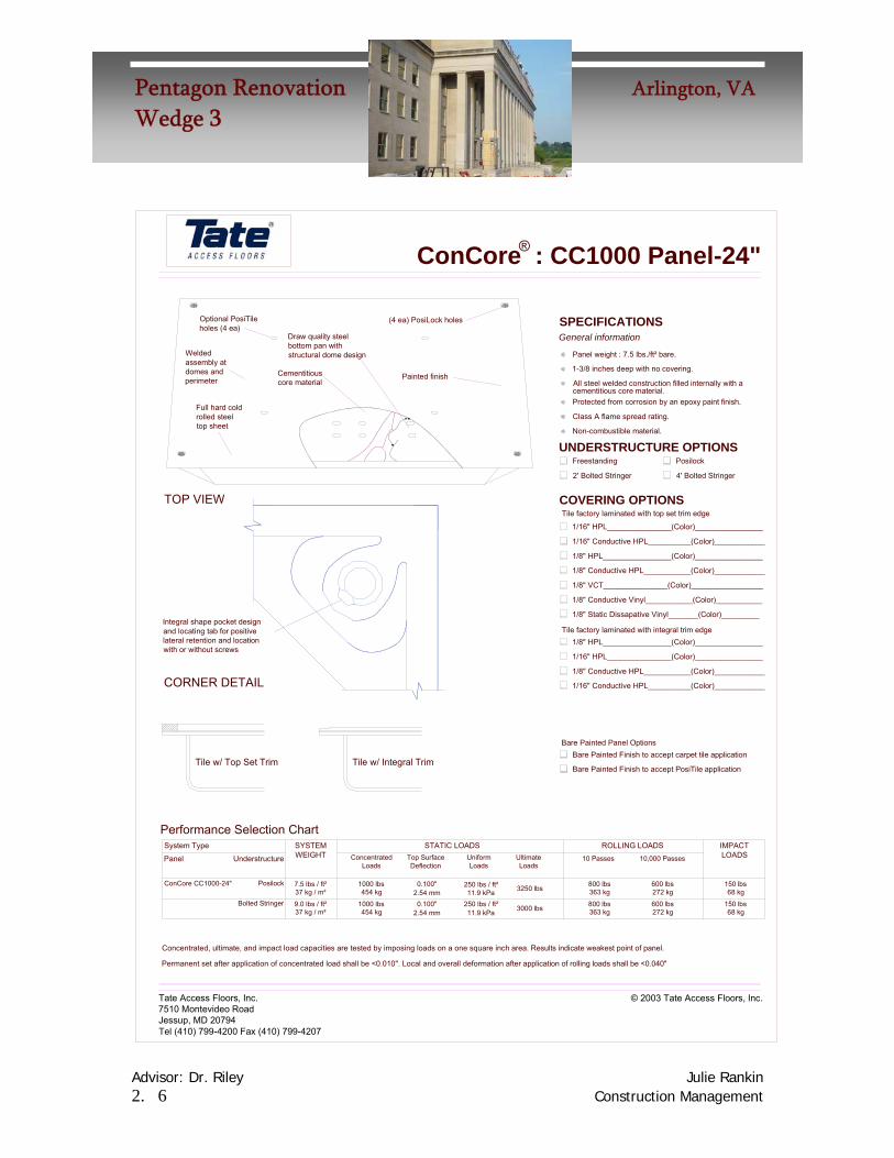
ConCore Panels
ConCore panels were chosen for their excellent
properties. They are fabricated from steel and filled with
controlled mixtures of cement. They offer extremely high
load tolerances, and create a solid floor system. The floor
is also free from noises occurring in the plenum space.

Advisor: Dr. Riley Julie Rankin 2. 5 Construction Management
Pentagon Renovation Arlington, VAWedge 3
This chart summarizes the most commonly available ConCore access panels. It
shows maximum static, rolling and impact loads, as well as the system total weight.
This is the chart that was used to select the most appropriate panels for general office,
control room and computer room spaces.
ConCore® Performance Selection Chart
SYSTEM TYPE STATIC LOADS ROLLING LOADS
Panel Understructure
SYSTEM WEIGHT
ConcentratedLoads
UniformLoads
UltimateLoads
10 passes
10,000 passes
IMPACT LOADS
ConCore 1000
Bolted Stringer
9.5 lbs/ft2 46 kg/m2
1000 lbs 454 kg
250 lbs 113 kg
3300 lbs1497 kg
800 lbs 363 kgs
600 lbs 272 kgs
150 lbs 68 kg
Posilock 8.5 lbs/ft2 41 kg/m2
1000 lbs 454 kg
250 lbs 113 kg
3200 lbs1452 kg
800 lbs
363 kg
600 lbs 272 kg
100 lbs 45 kg
ConCore 1250
Bolted Stringer
10.5 lbs/ft2 51 kg/m2
1250 lbs 567 kg
300 lbs 136 kg
3850 lbs1746 kg
1000 lbs
454 kg
800 lbs 363 kg
150 lbs 68 kg
Posilock 9.5 lbs/ft2 46 kg/m2
1250 lbs 567 kg
300 lbs 136 kg
3750 lbs1701 kg
1000 lbs
454 kg
800 lbs 363 kg
100 lbs 45 kg
ConCore 1500
Bolted Stringer
11.5 lbs/ft2 56 kg/m2
1500 lbs 680 kg
375 lbs 170 kg
5100 lbs2313 kg
1250 lbs
567 kg
1000 lbs
454 kg 150 lbs 68 kg
Posilock 10.5 lbs/ft2 51 kg/m2
1500 lbs 680 kg
375 lbs 170 kg
4600 lbs2087 kg
1250 lbs
567 kg
1000 lbs
454 kg 100 lbs 45 kg
ConCore 2000
Bolted Stringer
12.5 lbs/ft2 61 kg/m2
2000 lbs 907 kg
500 lbs 227 kg
6100 lbs2767 kg
1500 lbs
680 kg
1250 lbs
567 kg 150 lbs 68 kg
ConCore 2500
Bolted Stringer
13.5 lbs/ft2 66 kg/m2
2500 lbs 1134 kg
625 lbs 284 kg
6900 lbs3130 kg
1500 lbs
680 kg
2000 lbs
907 kg 150 lbs 68 kg
Note: Loads applied on a one square inch area. Results above indicate weakest point of panel.
Advisor: Dr. Riley Julie Rankin 2. 6 Construction Management
Pentagon Renovation Arlington, VAWedge 3
Tile factory laminated with integral trim edgeIntegral shape pocket designand locating tab for positivelateral retention and locationwith or without screws
Permanent set after application of concentrated load shall be <0.010". Local and overall deformation after application of rolling loads shall be <0.040"
Concentrated, ultimate, and impact load capacities are tested by imposing loads on a one square inch area. Results indicate weakest point of panel.
250 lbs / ft²0.100"1000 lbs7.5 lbs / ft²PosilockConCore CC1000-24"
Tate Access Floors, Inc.7510 Montevideo RoadJessup, MD 20794Tel (410) 799-4200 Fax (410) 799-4207
Bolted Stringer37 kg / m²9.0 lbs / ft²
37 kg / m²
454 kg1000 lbs
454 kg
2.54 mm0.100"
2.54 mm250 lbs / ft²11.9 kPa
11.9 kPa
Understructure
Performance Selection Chart
Panel
System Type
Tile w/ Top Set Trim
CORNER DETAIL
Tile w/ Integral Trim
SYSTEMWEIGHT Concentrated
Loads
STATIC LOADSTop SurfaceDeflection
UniformLoads
150 lbs600 lbs800 lbs3250 lbs
© 2003 Tate Access Floors, Inc.
68 kg150 lbs
68 kg
3000 lbs 363 kg800 lbs
363 kg
600 lbs272 kg
272 kg
1/8" Conductive HPL___________(Color)____________
1/16" Conductive HPL__________(Color)____________
Bare Painted Finish to accept PosiTile application
Bare Painted Finish to accept carpet tile application
1/8" HPL________________(Color)________________
1/16" HPL_______________(Color)________________
IMPACTLOADS
ROLLING LOADSUltimateLoads
10 Passes 10,000 Passes
Bare Painted Panel Options
ConCore : CC1000 Panel-24"
Weldedassembly atdomes andperimeter
Cementitiouscore material
TOP VIEW
Full hard coldrolled steeltop sheet
Painted finish
Optional PosiTileholes (4 ea)
(4 ea) PosiLock holes
Draw quality steelbottom pan withstructural dome design
1-3/8 inches deep with no covering.
4' Bolted Stringer
1/16" HPL_______________(Color)________________
1/8" Conductive Vinyl___________(Color)___________
1/8" Conductive HPL___________(Color)____________
1/8" Static Dissapative Vinyl_______(Color)_________
1/8" VCT_______________(Color)_________________
1/8" HPL________________(Color)________________
1/16" Conductive HPL__________(Color)____________
UNDERSTRUCTURE OPTIONS
Protected from corrosion by an epoxy paint finish.
All steel welded construction filled internally with a
COVERING OPTIONSTile factory laminated with top set trim edge
2' Bolted Stringer
Non-combustible material.
Class A flame spread rating.
cementitious core material.
Freestanding Posilock
Panel weight : 7.5 lbs./ft² bare.
General informationSPECIFICATIONS
®

Advisor: Dr. Riley Julie Rankin 2. 7 Construction Management
Pentagon Renovation Arlington, VAWedge 3
Integral shape pocket designand locating tab for positivelateral retention and locationwith or without screws
Permanent set after application of concentrated load shall be <0.010". Local and overall deformation after application of rolling loads shall be <0.040"
Concentrated, ultimate, and impact load capacities are tested by imposing loads on a one square inch area. Results indicate weakest point of panel.
Tate Access Floors, Inc.7510 Montevideo RoadJessup, MD 20794Tel (410) 799-4200 Fax (410) 799-4207
Bolted Stringer
PosilockConCore CC1250-24"
49 kg / m²10.0 lbs / ft²
41 kg / m²8.5 lbs / ft²
567 kg1250 lbs
567 kg1250 lbs
2.54 mm0.100"
2.54 mm0.100"
14.3 kPa300 lbs / ft²
300 lbs / ft²14.3 kPa
Understructure
Performance Selection Chart
Panel
System Type
Tile w/ Top Set Trim
CORNER DETAIL
Tile w/ Integral Trim
SYSTEMWEIGHT Concentrated
Loads
STATIC LOADSTop SurfaceDeflection
UniformLoads
© 2003 Tate Access Floors, Inc.
68 kg150 lbs
68 kg150 lbs
3500 lbs
3750 lbs
454 kg1000 lbs
454 kg1000 lbs
800 lbs
800 lbs
363 kg
363 kg
1/8" Conductive HPL___________(Color)____________
1/16" Conductive HPL__________(Color)____________
Bare Painted Finish to accept PosiTile application
Bare Painted Finish to accept carpet tile application
1/8" HPL________________(Color)________________
1/16" HPL_______________(Color)________________
IMPACTLOADS
ROLLING LOADSUltimateLoads
10 Passes 10,000 Passes
Bare Painted Panel Options
Tile factory laminated with integral trim edge
ConCore : CC1250 Panel-24"
Weldedassembly atdomes andperimeter
Cementitiouscore material
TOP VIEW
Full hard coldrolled steeltop sheet
Painted finish
Optional PosiTileholes (4 ea)
(4 ea) PosiLock holes
Draw quality steelbottom pan withstructural dome design
1/16" HPL_______________(Color)________________
4' Bolted Stringer
1/8" Conductive Vinyl___________(Color)___________
1/8" Conductive HPL___________(Color)____________
1/8" Static Dissapative Vinyl_______(Color)_________
1/8" VCT_______________(Color)_________________
1/8" HPL________________(Color)________________
1/16" Conductive HPL__________(Color)____________
UNDERSTRUCTURE OPTIONS
Protected from corrosion by an epoxy paint finish.
All steel welded construction filled internally with a
COVERING OPTIONSTile factory laminated with top set trim edge
2' Bolted Stringer
1-3/8 inches deep with no covering.
Non-combustible material.
Class A flame spread rating.
cementitious core material.
Freestanding Posilock
Panel weight : 8.0 lbs./ft² bare.
General informationSPECIFICATIONS
®

Advisor: Dr. Riley Julie Rankin 2. 8 Construction Management
Pentagon Renovation Arlington, VAWedge 3
Permanent set after application of concentrated load shall be <0.010". Local and overall deformation after application of rolling loads shall be <0.040"
Concentrated, ultimate, and impact load capacities are tested by imposing loads on a one square inch area. Results indicate weakest point of panel.
STATIC LOADS
(4 ea) PosiLock holes
ConCore : CC1500 Panel-24"
Tate Access Floors, Inc.7510 Montevideo RoadJessup, MD 20794Tel (410) 799-4200 Fax (410) 799-4207
Tile w/ Top Set Trim
Bolted Stringer
Understructure
Performance Selection Chart
Integral shape pocket designand locating tab for positivelateral retention and locationwith or without screws
CORNER DETAIL
ConCore CC1500-24"
System Type
Panel
52 kg / m²10.5 lbs / ft²
680 kg1500 lbs
2.54 mm0.100"
ConcentratedLoads
SYSTEMWEIGHT
Tile w/ Integral Trim
Top SurfaceDeflection
Optional PosiTileholes (4 ea)
Weldedassembly atdomes andperimeter
TOP VIEW
Full hard coldrolled steeltop sheet
Cementitiouscore material
Painted finish
Draw quality steelbottom pan withstructural dome design
© 2003 Tate Access Floors, Inc.
ROLLING LOADS
1000 lbs454 kg
10,000 Passes
Bare Painted Panel Options
1/16" Conductive HPL__________(Color)____________
1/8" Conductive HPL___________(Color)____________
1/8" HPL________________(Color)________________Tile factory laminated with integral trim edge
Bare Painted Finish to accept PosiTile application
Bare Painted Finish to accept carpet tile application
1/16" HPL_______________(Color)________________
375 lbs / ft²17.9 kPa 5000 lbs 567 kg
1250 lbs
UniformLoads
UltimateLoads
10 Passes
68 kg150 lbs
IMPACTLOADS
1-3/8 inches deep with no covering.
Tile factory laminated with top set trim edge
1/8" Conductive Vinyl___________(Color)___________
1/8" Conductive HPL___________(Color)____________
1/8" Static Dissapative Vinyl_______(Color)_________
1/8" VCT_______________(Color)_________________
1/8" HPL________________(Color)________________
1/16" Conductive HPL__________(Color)____________
1/16" HPL_______________(Color)________________
COVERING OPTIONS2' Heavy Duty Bolted Stringer
4' Heavy Duty Bolted Stringer
UNDERSTRUCTURE OPTIONSNon-combustible material.
Class A flame spread rating.
Protected from corrosion by an epoxy paint finish.cementitious core material.All steel welded construction filled internally with a
Panel weight : 9.0 lbs./ft² bare.
SPECIFICATIONS
®
General information

Advisor: Dr. Riley Julie Rankin 2. 9 Construction Management
Pentagon Renovation Arlington, VAWedge 3
Ceiling Clearance
Because the concrete work was done quickly, and with little attention to detail
compared to today’s standards, many of the floor-to-ceiling heights vary throughout the
building. However, for stories two through four, the typical ceiling height is about 11’-
6”. As shown in the figure, a
seven inch beam from the
ceiling offers a 10’-10” space
beneath. If the panels are set
18” off the ground and a
gypsum board ceiling or other
ceiling type is installed flush
with the under-slung beams,
there is still a clearance of 9’-
2”, more than ample for the
office spaces and computer
rooms. If the air is returned
through an overhead plenum in drop ceiling, this ceiling height may still be very shallow.
If it were 8”, there is still over 8’ clearance for usable space, and plenty of room in the
overhead plenum for the plumbing.
10’-3”
14”
12’-10”
10’-10”
7”
Advisor: Dr. Riley Julie Rankin 2. 10 Construction Management
Pentagon Renovation Arlington, VAWedge 3
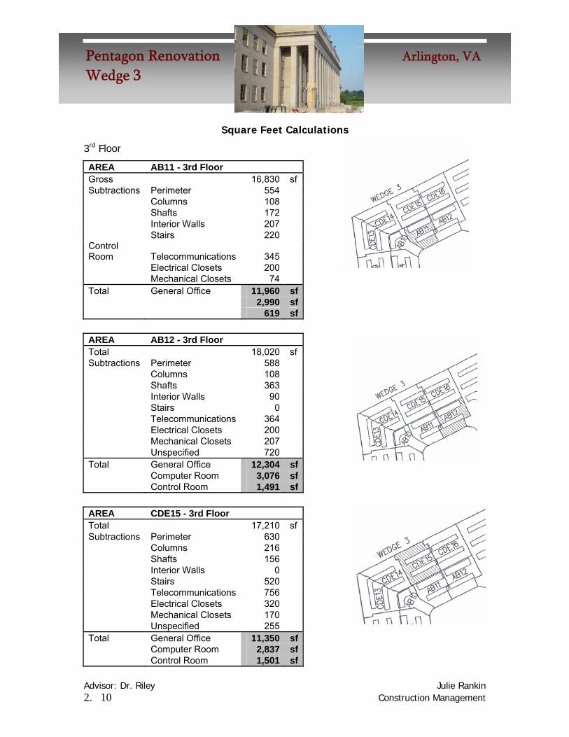
Square Feet Calculations
3rd Floor
AREA AB11 - 3rd Floor Gross 16,830 sf Subtractions Perimeter 554 Columns 108 Shafts 172 Interior Walls 207 Stairs 220 Control Room Telecommunications 345 Electrical Closets 200 Mechanical Closets 74 Total General Office 11,960 sf 2,990 sf 619 sf
AREA AB12 - 3rd Floor Total 18,020 sf Subtractions Perimeter 588 Columns 108 Shafts 363 Interior Walls 90 Stairs 0 Telecommunications 364 Electrical Closets 200 Mechanical Closets 207 Unspecified 720 Total General Office 12,304 sf Computer Room 3,076 sf Control Room 1,491 sf
AREA CDE15 - 3rd Floor Total 17,210 sf Subtractions Perimeter 630 Columns 216 Shafts 156 Interior Walls 0 Stairs 520 Telecommunications 756 Electrical Closets 320 Mechanical Closets 170 Unspecified 255 Total General Office 11,350 sf Computer Room 2,837 sf Control Room 1,501 sf
Advisor: Dr. Riley Julie Rankin 2. 11 Construction Management
Pentagon Renovation Arlington, VAWedge 3
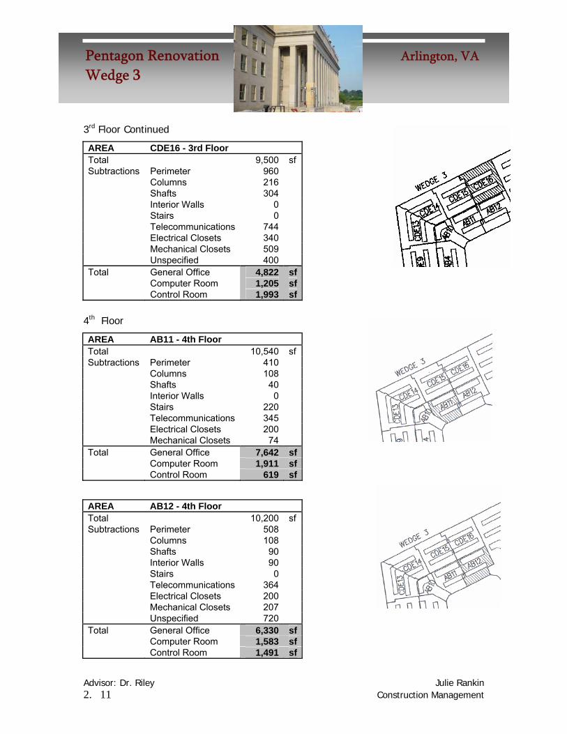
3rd Floor Continued
AREA CDE16 - 3rd Floor Total 9,500 sf Subtractions Perimeter 960 Columns 216 Shafts 304 Interior Walls 0 Stairs 0 Telecommunications 744 Electrical Closets 340 Mechanical Closets 509 Unspecified 400 Total General Office 4,822 sf Computer Room 1,205 sf Control Room 1,993 sf
4th Floor
AREA AB11 - 4th Floor Total 10,540 sf Subtractions Perimeter 410 Columns 108 Shafts 40 Interior Walls 0 Stairs 220 Telecommunications 345 Electrical Closets 200 Mechanical Closets 74 Total General Office 7,642 sf Computer Room 1,911 sf Control Room 619 sf
AREA AB12 - 4th Floor Total 10,200 sf Subtractions Perimeter 508 Columns 108 Shafts 90 Interior Walls 90 Stairs 0 Telecommunications 364 Electrical Closets 200 Mechanical Closets 207 Unspecified 720 Total General Office 6,330 sf Computer Room 1,583 sf Control Room 1,491 sf
Advisor: Dr. Riley Julie Rankin 2. 12 Construction Management
Pentagon Renovation Arlington, VAWedge 3
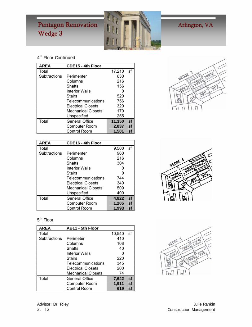
4th Floor Continued
AREA CDE15 - 4th Floor Total 17,210 sf Subtractions Perimenter 630 Columns 216 Shafts 156 Interior Walls 0 Stairs 520 Telecommunications 756 Electrical Closets 320 Mechanical Closets 170 Unspecified 255 Total General Office 11,350 sf Computer Room 2,837 sf Control Room 1,501 sf
AREA CDE16 - 4th Floor Total 9,500 sf Subtractions Perimenter 960 Columns 216 Shafts 304 Interior Walls 0 Stairs 0 Telecommunications 744 Electrical Closets 340 Mechanical Closets 509 Unspecified 400 Total General Office 4,822 sf Computer Room 1,205 sf Control Room 1,993 sf
5th Floor
AREA AB11 - 5th Floor Total 10,540 sf Subtractions Perimeter 410 Columns 108 Shafts 40 Interior Walls 0 Stairs 220 Telecommunications 345 Electrical Closets 200 Mechanical Closets 74 Total General Office 7,642 sf Computer Room 1,911 sf Control Room 619 sf

Advisor: Dr. Riley Julie Rankin 2. 13 Construction Management
Pentagon Renovation Arlington, VAWedge 3
5th Floor Continued
AREA AB12 - 5th Floor Total 10,200 sf Subtractions Perimeter 508 Columns 108 Shafts 90 Interior Walls 90 Stairs 0 Telecommunications 364 Electrical Closets 200 Mechanical Closets 207 Unspecified 720 Total General Office 6,330 sf Computer Room 1,583 sf Control Room 1,491 sf
AREA CDE15 - 5th Floor Total 17,210 sf Subtractions Perimeter 630 Columns 216 Shafts 156 Interior Walls 0 Stairs 520 Telecommunications 756 Electrical Closets 320 Mechanical Closets 170 Unspecified 255 Total General Office 11,350 sf Computer Room 2,837 sf Control Room 1,501 sf
AREA CDE16 - 5th Floor Total 9,500 sf Subtractions Perimeter 960 Columns 216 Shafts 304 Interior Walls 0 Stairs 0 Telecommunications 744 Electrical Closets 340 Mechanical Closets 509 Unspecified 400 Total General Office 4,822 sf Computer Room 1,205 sf Control Room 1,993 sf

Advisor: Dr. Riley Julie Rankin 2. 14 Construction Management
Pentagon Renovation Arlington, VAWedge 3
Total Square Footages
WEDGE 3 TOTALS Subdivisions General Office 100,723 Computer Room 25,181 Control Room 16,812 Total 142,716 sf

Advisor: Dr. Riley Julie Rankin 2. 15 Construction Management
Pentagon Renovation Arlington, VAWedge 3
Mechanical Breadth
Problem Statement
As shown in the beginning of this section, the utilities including the treated air
are delivered through an overhead bulkhead in several of the office areas. The air is
delivered overhead, and the return grills are also located overhead in the same ceiling.
There are some problems associated with this. If the air is supplied and returned from
the ceiling, there may not be optimal circulation. This is especially so in the winter,
when the warm treated air will stay near the ceiling, potentially causing drafts or less
than optimal comfort.
I think that with a raised floor, it would be more efficient to deliver the air from
the floor near the windows and have the return air go through the ceiling in the center.
The following diagram demonstrates the logic of the analysis by showing the
probable air circulation from each system.
Current System Proposed System
Supply
ReturnSupply
Return
Advisor: Dr. Riley Julie Rankin 2. 16 Construction Management
Pentagon Renovation Arlington, VAWedge 3
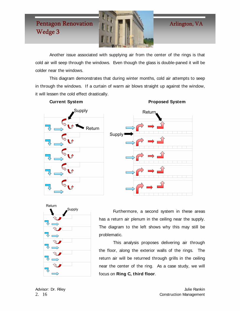
Another issue associated with supplying air from the center of the rings is that
cold air will seep through the windows. Even though the glass is double-paned it will be
colder near the windows.
This diagram demonstrates that during winter months, cold air attempts to seep
in through the windows. If a curtain of warm air blows straight up against the window,
it will lessen the cold effect drastically.
Current System Proposed System
Furthermore, a second system in these areas
has a return air plenum in the ceiling near the supply.
The diagram to the left shows why this may still be
problematic.
This analysis proposes delivering air through
the floor, along the exterior walls of the rings. The
return air will be returned through grills in the ceiling
near the center of the ring. As a case study, we will
focus on Ring C, third floor.
Supply
ReturnSupply
Return
SupplyReturn

Advisor: Dr. Riley Julie Rankin 2. 17 Construction Management
Pentagon Renovation Arlington, VAWedge 3
During summer months, the warm air will also be stopped at the window and
mixed with the cool air rising from the floor.
Current System Proposed System
SupplyReturn
Supply
Return
Advisor: Dr. Riley Julie Rankin 2. 18 Construction Management
Pentagon Renovation Arlington, VAWedge 3
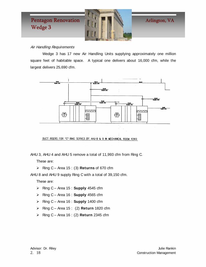
Air Handling Requirements
Wedge 3 has 17 new Air Handling Units supplying approximately one million
square feet of habitable space. A typical one delivers about 16,000 cfm, while the
largest delivers 25,690 cfm.
AHU 3, AHU 4 and AHU 5 remove a total of 11,993 cfm from Ring C.
These are:
Ring C – Area 15 : (3) Returns of 670 cfm
AHU 8 and AHU 9 supply Ring C with a total of 39,150 cfm.
These are:
Ring C – Area 15 : Supply 4545 cfm
Ring C – Area 16 : Supply 4565 cfm
Ring C – Area 16 : Supply 1400 cfm
Ring C – Area 15 : (2) Return 1820 cfm
Ring C – Area 16 : (2) Return 2345 cfm

Advisor: Dr. Riley Julie Rankin 2. 19 Construction Management
Pentagon Renovation Arlington, VAWedge 3
The universal space plan is quite efficient in that it uses minimal duct work. A quick
summary of the take-offs show that there is a total of 1,830 lf of duct work on third
floor, C Ring, of which 410 lf is flexible 10” diameter duct work. A major goal for this
analysis is to attempt the new delivery system without using any more duct.
C - 15 C - 16 Size lf Size lf
Flex 10Φ 210 Flex 10Φ 21010Φ 469 6Φ 1612Φ 135 8Φ 2212x10 15 10Φ 33016x10 20 12Φ 30524x12 6 12x10 92 Total 855 Total 975
Total Wedge 3 1830 lf

Advisor: Dr. Riley Julie Rankin 2. 20 Construction Management
Pentagon Renovation Arlington, VAWedge 3
Duct Plan
Existing Duct
This is a copy of the HVAC
design for a small section of Ring C
third floor. It depicts the supply
ducts, diffusers and the return ducts
for a general office space. It shows
flexible duct work that delivers air
from the supply ducts to each
diffuser.
Changes
In the new plan all flexible duct is removed, because the metal duct delivers the
air directly to the diffusers under the windows. This saves 410 lf of flexible 10” diameter
duct. In these places, there is no additional rectangular duct required either. This
figure shows how the flexible duct is eliminated and the rectangular duct is rerouted.
Lightwell Space
Exterior Wall
Air supply
Flexible Duct
Supply Duct
Return Duct
Lightwell Space
Exterior Wall
Supply Duct
Re-Route Duct along window(uses no more material here)
Supply Duct
Diffuser

Advisor: Dr. Riley Julie Rankin 2. 21 Construction Management
Pentagon Renovation Arlington, VAWedge 3
Riser Alterations
The two drawings below show an example of the existing riser diagrams. These
will all need to be redesigned so that the return and supply air are in the right place.
The following two pages show the existing riser diagram for this area and the
proposed new one, where the supply vents are in different locations.

Original Riser Diagram This diagram shows the supply and relief flow in cfm for an existing section of Ring C.

Revised Riser Diagram This image shows how the supply sections could be cut near the slab floor, rather than near the ceiling. The duct work could then deliver the air underneath the access floor.

Access Floor Section This section demonstrates where the major utilities will run through one level of one floor. The supply and return air, the e” fire protection pipes, and the cable trays and conduit are shown.

Advisor: Dr. Riley Julie Rankin 2. 25 Construction Management
Pentagon Renovation Arlington, VAWedge 3
Cost
The use of less duct work has a small cost savings. Removing the 3,960 lf of
flexible duct work amounts to a savings of $5,904.
However, the cost of installing access floor will be much greater than installing
carpet. The table below summarizes the cost of installing access flooring.
Material Labor Totals
General Office
$755,422.50 $302,169.00 $1,057,591.50
Computer Room
$188,857.50 $75,543.00 $264,400.50
Control Room
$126,090.00 $50,436.00 $176,526.00
Totals $1,070,370.00 $428,148.00 $1,498,518.00

Schedule SIPS Schedule – Existing The following key and schedule show the existing SIPS (Short Interval Production Schedule).

The existing SIPS schedule is complete on August 27th, 2007.

SIPS Schedule – Revised To successfully install the access floor, first the pedestals on which the panels rest are laid out, then bolted into the concrete
slab. After all the underneath utilities are installed, such as mechanical duct, cable trays and conduit, the floor panels may be installed.
For this process to fit into one SIPS block, the entire process must take up to one week per zone to install. It is a generous assumption to give a full day for the following tasks: One day is required to lay out the grid for the support pedestals, one day to place the pedestals, one day to bolt them into the concrete, and two days to install the panels. Therefore, this fits easily into a five day week. However, after the first three days, a five day slot will be used to install conduit and cable trays. Then the panels will be installed. This results in an additional week at week nine of the SIPS schedule.
The new key is shown below.
Week 1 Week 2 Task Mon Tue Wed Thurs Fri Mon Tue Wed Thurs Fri
Layout a grid of 2'x2' for pedestals Place pedestals onto 2'x2' grid
Bolt pedestals into concrete Install cable tray
Pull conduits Install access panels

The new schedule with the additional week is shown below. The new completion date is September 3rd, 2007. However, the SIPS schedule will be complete two months before substantial completion and turnover, meaning this additional week has no effect on the overall schedule.

Advisor: Dr. Riley Julie Rankin 2. 30 Construction Management
Pentagon Renovation Arlington, VAWedge 3
Conclusions
Access floor makes a lot of sense in these office regions. It will be easy to
maintain all mechanical and electrical systems. Also, it will keep the plumbing away
from the mechanical systems, preventing some trade clashing.
The major benefit is the improved air circulation which will improve the comfort
level for the tenants. The new system also seems more efficient. In Ring C third floor
alone, 410 linear feet of duct was saved, and a total of 3,690 lf throughout the designed
spaces.
The space under the raised floor may hold all the electrical power in cable trays,
data and telecommunications wires, environmental control and air conditioning and
mechanical supply ducts. This will improve the construction speed and ease future
tenant space changes.
However, the cost of installing an access floor is much greater than standard
commercial carpet. For about one million extra dollars, the improved circulation and
ease for future maintenance and expansion of the under floor utilities should be worth
this cost. It is important to note that the SIPS schedule will be extended by one extra
week’s length for the installation of the floor, but the overall project schedule will not be
affected.

Advisor: Dr. Riley Julie Rankin 3. 1 Construction Management
Pentagon Renovation Arlington, VAWedge 3
Demolition
Background .............................................................................3.2 Problem Statement..................................................................3.3 Proposal ..................................................................................3.3 Exisiting Situation ....................................................................3.3 New Plan .................................................................................3.7 Costs ..................................................................................... 3.10 Conclusion............................................................................. 3.10
Advisor: Dr. Riley Julie Rankin 3. 2 Construction Management
Pentagon Renovation Arlington, VAWedge 3
Demolition
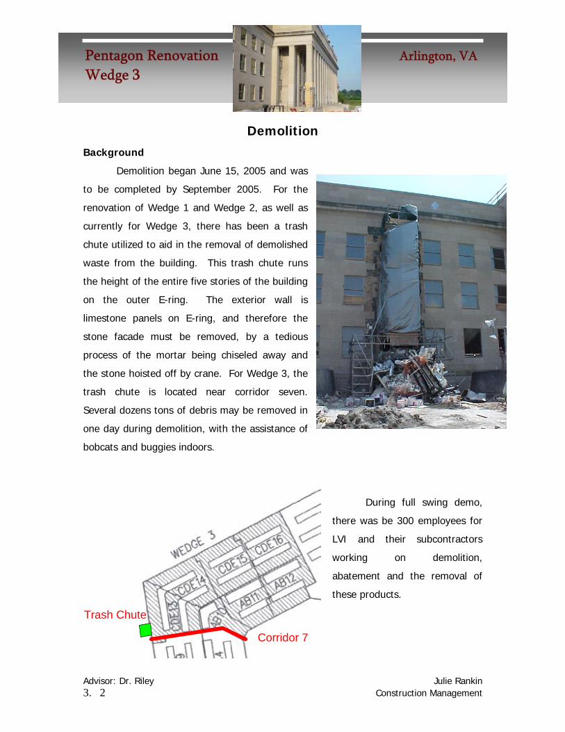
Background
Demolition began June 15, 2005 and was
to be completed by September 2005. For the
renovation of Wedge 1 and Wedge 2, as well as
currently for Wedge 3, there has been a trash
chute utilized to aid in the removal of demolished
waste from the building. This trash chute runs
the height of the entire five stories of the building
on the outer E-ring. The exterior wall is
limestone panels on E-ring, and therefore the
stone facade must be removed, by a tedious
process of the mortar being chiseled away and
the stone hoisted off by crane. For Wedge 3, the
trash chute is located near corridor seven.
Several dozens tons of debris may be removed in
one day during demolition, with the assistance of
bobcats and buggies indoors.
During full swing demo,
there was be 300 employees for
LVI and their subcontractors
working on demolition,
abatement and the removal of
these products.
Corridor 7
Trash Chute
Advisor: Dr. Riley Julie Rankin 3. 3 Construction Management
Pentagon Renovation Arlington, VAWedge 3
Problem Statement
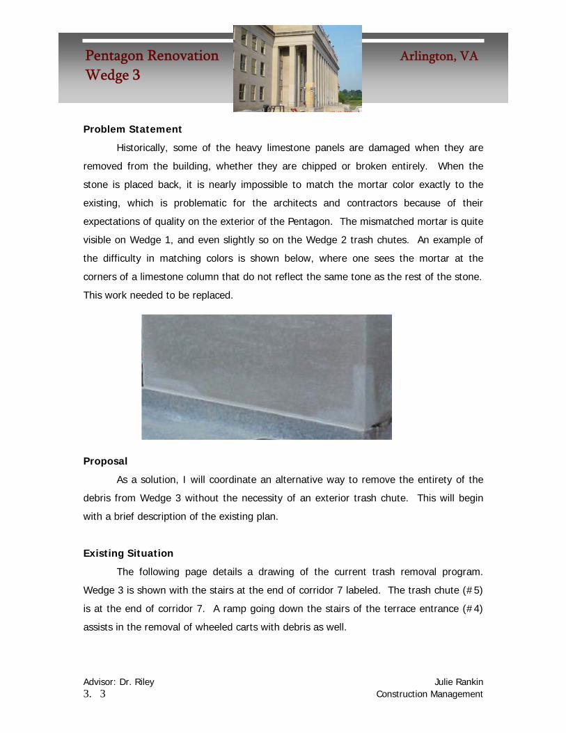
Historically, some of the heavy limestone panels are damaged when they are
removed from the building, whether they are chipped or broken entirely. When the
stone is placed back, it is nearly impossible to match the mortar color exactly to the
existing, which is problematic for the architects and contractors because of their
expectations of quality on the exterior of the Pentagon. The mismatched mortar is quite
visible on Wedge 1, and even slightly so on the Wedge 2 trash chutes. An example of
the difficulty in matching colors is shown below, where one sees the mortar at the
corners of a limestone column that do not reflect the same tone as the rest of the stone.
This work needed to be replaced.
Proposal
As a solution, I will coordinate an alternative way to remove the entirety of the
debris from Wedge 3 without the necessity of an exterior trash chute. This will begin
with a brief description of the existing plan.
Existing Situation
The following page details a drawing of the current trash removal program.
Wedge 3 is shown with the stairs at the end of corridor 7 labeled. The trash chute (#5)
is at the end of corridor 7. A ramp going down the stairs of the terrace entrance (#4)
assists in the removal of wheeled carts with debris as well.


Advisor: Dr. Riley Julie Rankin 3. 5 Construction Management
Pentagon Renovation Arlington, VAWedge 3
Utility Risers
The scope of Wedge 3 involves several new utility risers, many of which are
located along the main radial corridors 7 and 8. These penetrations are cut during the
demolition process. If these penetrations are used to lower trash from the upper levels
to the ground level, the debris may be removed from the entrance at corridor 7. This
means that no limestone masonry shall be removed from the façade.
Also, there are several existing penetrations that are scheduled to be infilled
after the demolition process is complete. One such slab that is the most conveniently
located exists between column line 7.22 and 7.23. It is directly near the mall terrace
entrance which will serve as the exit route for the trash. From level 2 through 5, there
is a 9’ by 7’ square. The details describe that it is to be eventually filled with a metal
deck and a concrete slab. However, during demolition this shaft could serve as the main
trash chute, for it is equivalent in size to the one that was on the exterior façade of the
building.

Advisor: Dr. Riley Julie Rankin 3. 6 Construction Management
Pentagon Renovation Arlington, VAWedge 3
Another existing penetration that will be filled exists along corridor 8. It is a 10’
by 7’ space and rises from the ground ceiling to the fifth floor, making it another ideal
location for an interior trash chute.
These pictures below show a shaft along ring C where it meets the corridor. This
shaft is a trapezoid of the approximate dimensions 6’ by 10’, and was cut during the
demolition phase of Wedge 3 in June 2005. This is another example of a space large
enough for an interior trash chute to be installed.
Advisor: Dr. Riley Julie Rankin 3. 7 Construction Management
Pentagon Renovation Arlington, VAWedge 3
New Plan
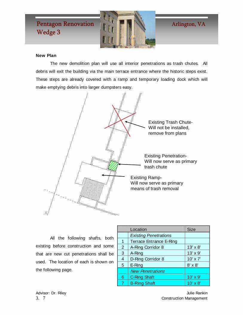
The new demolition plan will use all interior penetrations as trash chutes. All
debris will exit the building via the main terrace entrance where the historic steps exist.
These steps are already covered with a ramp and temporary loading dock which will
make emptying debris into larger dumpsters easy.
Existing Ramp-Will now serve as primarymeans of trash removal
Existing Penetration-Will now serve as primarytrash chute
Existing Trash Chute-Will not be installed,remove from plans
All the following shafts, both
existing before construction and some
that are new cut penetrations shall be
used. The location of each is shown on
the following page.
Location Size Existing Penetrations 1 Terrace Entrance E-Ring 2 A-Ring Corridor 8 13' x 8' 3 A-Ring 13' x 9' 4 D-Ring Corridor 8 10' x 7' 5 E-Ring 8' x 8' New Penetrations 6 C-Ring Shaft 10' x 9' 7 B-Ring Shaft 10' x 8'


Advisor: Dr. Riley Julie Rankin 3. 9 Construction Management
Pentagon Renovation Arlington, VAWedge 3
Under the new proposition, the same bobcats will still be used. However they
will deliver demolished material to the interior trash chutes.
Part of the new plan is also to show what regions will use which trash chute.
Below is a color coded scheme showing the flow of debris.
Advisor: Dr. Riley Julie Rankin 3. 10 Construction Management
Pentagon Renovation Arlington, VAWedge 3
Costs
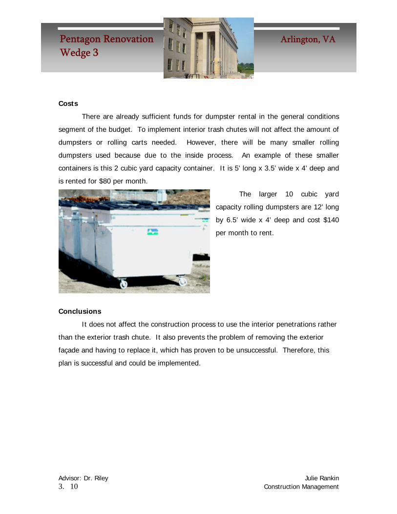
There are already sufficient funds for dumpster rental in the general conditions
segment of the budget. To implement interior trash chutes will not affect the amount of
dumpsters or rolling carts needed. However, there will be many smaller rolling
dumpsters used because due to the inside process. An example of these smaller
containers is this 2 cubic yard capacity container. It is 5’ long x 3.5’ wide x 4’ deep and
is rented for $80 per month.
The larger 10 cubic yard
capacity rolling dumpsters are 12’ long
by 6.5’ wide x 4’ deep and cost $140
per month to rent.
Conclusions
It does not affect the construction process to use the interior penetrations rather
than the exterior trash chute. It also prevents the problem of removing the exterior
façade and having to replace it, which has proven to be unsuccessful. Therefore, this
plan is successful and could be implemented.

Advisor: Dr. Riley Julie Rankin 4. 1 Construction Management
Pentagon Renovation Arlington, VAWedge 3
Dynamic and Large Project Teams Research
Introduction ........................................................................................... 4.2 Team Development ............................................................................... 4.4
Team Dynamics..................................................................................... 4.6
When Problems Arise........................................................................... 4.6
Large Project Teams............................................................................. 4.6 Case Study – The Pentagon............................................................. 4.8 Problem 1 – Document Control......................................................... 4.9

Advisor: Dr. Riley Julie Rankin 4. 2 Construction Management
Pentagon Renovation Arlington, VAWedge 3
Dynamic and Large Project Teams – Dealing With Less Than Ideal Project Situations
Introduction
It has been researched that most teams fall into the category of two to twenty-
five members. The groups that are considered the most manageable and efficient are
groups involving five to nine people. When a project is so large that there are many
more people involved, there are several potential problems. With teams of people over
nine members, often conversation becomes centralized. No one person gets across
their opinions effectively, simply from the lack of time and confusion from the numbers.
Another odd phenomenon with large groups of people is that each person’s
productivity decreases when they work with increasingly large numbers of people on any
one assignment. In any case where
the productivity of a team can be
measured numerically, it is related
directly to the number of people
working in the team. These two
charts aid in visualizing this
phenomenon.
It is important to have a team
filled with individuals with the
appropriate skills necessary for the
proper and efficient completion of the
project. When there needs to be a staff
of several dozen people, these skills
tend to become more specialized. As
an example, I will discuss the project
teams for two separate projects.

Advisor: Dr. Riley Julie Rankin 4. 3 Construction Management
Pentagon Renovation Arlington, VAWedge 3
Project 1
Project: Renovation and addition to the Recreation Hall on the Penn State Campus
Cost: Approximately $11 million
General Contractor: Gilbane
Gilbane Project Team: 1 project manager, 1 superintendent, 1 intern
Project 2
Project: Renovation of Wedge 3 at the Pentagon in Arlington, VA
Cost: Approximately $370 million
General Contractor: Hensel Phelps
HP Project Team: About five dozen employees
This diagram shows only the management at the Pentagon Wedge 3 Project
Advisor: Dr. Riley Julie Rankin 4. 4 Construction Management
Pentagon Renovation Arlington, VAWedge 3
These two scenarios demonstrate the vast difference between smaller
construction projects and larger ones. The members of this first team are responsible
for all project management, as well as recording daily onsite work, communicating with
subcontractors, and tracking their own paper work. The second project is a strong
example of specialized work, where there are entire departments of people working on
specific tasks such as Document Control, Quality Control, Office Engineering tasks, Field
Engineering Tasks, and more.
Both teams, whether of three individuals or fifty have the same responsibilities.
These individual responsibilities include:
Carrying out all tasks which are assigned
Providing administrative support
Assist managers in achieving all team objectives and goals
Advising managers in risky situations or crises
Provide all required documentation and information
Maintain organized and efficient work environment
Team Development
A major concern when dealing with larger teams arises in the development of
the team. A survey of industry members resulted in a better understanding of some of
the major concerns when developing unusually large project teams:
How will many individuals function together?
Will there be personal interactions affecting the team goals?
Will the level of professionalism remain high?
How can several people remain a cohesive and functioning team throughout the entirety of the project?

Advisor: Dr. Riley Julie Rankin 4. 5 Construction Management
Pentagon Renovation Arlington, VAWedge 3
After interviewing several industry members, there were some conclusions drawn
about selecting members for project teams, and dealing with the diversities of people:
When developing project teams during the preconstruction phase, project
managers make several decisions regarding their management and staff positions. A
summary of their responses for strong team member selection follows:
When selecting employees for management positions in a project team:
• Select those who focus on establishing costumer relationships
• Individuals with a vision of the finished project
• Those with goal setting, negotiation and problem solving skills
• Ones who have demonstrated leadership and team development skills
When selecting employees for staff positions, to work under upper management,
the idea criteria these managers look for in their personnel includes:
• Those with technical proficiency in all necessary disciplines
• Wide variety of experiences
• Amount of previous experience of similar successful projects
• Individuals who demonstrate willingness to teach subordinates to grow in
knowledge and responsibility
Two very important points mentioned over and over by industry leaders suggest
finding people for all levels of a project team with high levels of self confidence in their
abilities, as well as a desire to grown and learn in new areas.

Advisor: Dr. Riley Julie Rankin 4. 6 Construction Management
Pentagon Renovation Arlington, VAWedge 3
Team dynamics
When dealing with teams of various sizes, it is important for managers to promote
learning and development for individuals for their future growth in responsibility. This
involves continual reinforcement to all members of the importance of the finish product,
as well as reminders of the customers’ confidence in each member and their
expectations of quality for the product for which they are paying. The manager of
Industrial Resources, Inc. in Pittsburgh advises to “… try to establish open customer
relations at each level of responsibility. We try to team-up with our customer’s team at
each level, while reporting communications up the ladder.” A strong manager will
inform their team of all major issues regarding the budget and schedules, as well as
involving them by asking for suggestions to solve problems.
Perhaps the most crucial thing for a team to do initially is to develop goals.
Having a common purpose is the reason for creating teams, but generating concern
about the purpose from each member is crucial with large numbers.
When Problems Arise
It commonly occurs that a less than ideal project team is created, often because
of the lack of staff availability. There are several steps that should be taken by
managers to alleviate any friction between members of a team. Friction occurs most
often when a new member is introduced into a team, or at the upstart of a project,
when members are familiarizing themselves with the practices and personal behaviors of
the people they work with.
As stated by one manager, “Friction (in the work place) comes from someone
thinking that the other guy isn’t doing his job or share of the work.” This manager
recommends focusing on the successful project outcome as the reason for teaching and
learning. By explaining the expectations to both the teacher and the learner in a one-
on-one setting, there is an opportunity for a face to face discussion which should remind
members of the importance of having mutual respect for all parties involved in the

Advisor: Dr. Riley Julie Rankin 4. 7 Construction Management
Pentagon Renovation Arlington, VAWedge 3
project. Each team member should report to a manager if they are not receiving this
respect.
Managers may make all team members feel this respect by announcing an open
door policy for resolution of any problems they occur, while continually reminding them
that a successful project is the outcome in the balance. Managers must also infer that
unproductive friction won’t be tolerated, as it puts the entire company’s reputation and
success at risk.
Suggestions for alleviating issues between team members:
1. Consider each day a team development exercise in real time.
2. Be communicative to all members about problems they are creating. Private
meetings with members will remind them of their responsibilities privately.
3. Remember that “trouble makers”, or those who are difficult to work with have
probably heard this before from a previous manager and are aware that they
need to correct their behavior. Reinforcement of this will remind them to
redevelop personal goals.
4. Remind any members involved in conflict that the successful outcome should be
their vision, goal, and obligation to the company, and that the company can not
tolerate behavior disruptive to the common goal.
Some common responses of failed methods of dealing with team members:
1. “I don’t believe off-site seminars are effective by themselves. People who are
sent to these feel singled-out as bad apples, and may become more defensive
and build more excuses around their private fortress.”
2. Do not embarrass trouble makers by reprimanding them in front of others.
Private discussions will not make them feel alienated from the team.
Team members, especially in larger groups, tend to work too independently on
problems. Often times this occurs in the more senior people of a company, where upper

Advisor: Dr. Riley Julie Rankin 4. 8 Construction Management
Pentagon Renovation Arlington, VAWedge 3
managers try to do all the problem solving themselves. To create a more cohesive team,
close supervision by all team members of each other’s progress is recommended to
identify this tendency. Once identified, the solution is often simple and involves proper
communication of the problem. Though it is often difficult to approach senior team
members with advice, the stalled problem solver often welcomes this approach. It
reminds them that their team is indeed capable of more responsibility and that they are
present to continually reinforce the managers decisions with their own personal problem
solving skills.
All members should schedule personal brain-storming sessions of self-evaluation.
Often these personal “time-outs” offer some new directions to explore for developing
solutions.
Research Focus – Large Teams
Case Study – The Pentagon
Now that some issues such as personal dynamics and problem solving strategies
have been discussed, the focus of this research points to unusually large project teams.
The general contractor Hensel Phelps employs a team at the Pentagon Renovation
project of several dozen people.
Communication is important, but often is disrupted when passing information
along such a long chain of people. Everyone needs to collaborate with each other, the
customer, and the subcontractors.
The following challenges are real challenges that occur at the Pentagon project.
After the problems are discussed and analyzed, there will be some proposed solutions to
reduce the problems.

Advisor: Dr. Riley Julie Rankin 4. 9 Construction Management
Pentagon Renovation Arlington, VAWedge 3
Typical Pentagon Challenge – Document Control
At the Pentagon, the overlapping matrix teams serve multiple functions to one
another. By inspection of the Operations Team, one notes the major operations
managers in green, the office staff highlighted by blue, the secretarial staff in purple,
and the document control staff in red. Each of these teams has its own designated
manager or leader. Take note that the document control team has five members to its
single team.
A major problem with so many people working on such a large project arises
with the document control. This team is responsible for continually updating and
maintaining copies of the plans and specification sheets for Wedge 3. They are separate
from the office team. A task of the office team is sending the proper drawings to the

Advisor: Dr. Riley Julie Rankin 4. 10 Construction Management
Pentagon Renovation Arlington, VAWedge 3
subcontractors under their responsibility. It is a common occurrence for a subcontractor
to receive drawings from an office engineer, while another updated set of drawings
exists in document control. However, there is no record of which drawings are mailed
to subcontractors and at what time, and it is difficult for an office engineer to track the
changes made by document control. This has lead to subcontractors having incomplete
or entirely incorrect plans on multiple occasions. The documents change throughout
construction as it is a design build delivery, as well as the fact that tenants of the
building make design changes rather often, causing change orders and redesigned
interior spaces.
Proposed Solution
Going digital is a major advantage for any sized project, however I see the
benefit of being more digital as exponentially higher for a scenario such as this. All
employees of Hensel Phelps and PenRen at the Pentagon have access to a shared
intranet for information sharing. However, the project plans are kept on paper copies in
a control center near the job site. At this center, the document control manager has
access to the digital plans, but the others in the office do not. Sharing these plans over
the intranet, for members of the contractors team would not only minimize this chance
for office employees to send obsolete drawings, it would also greatly increase efficiency
in sending drawings.
Document control exists as a way to maintain who is receiving this confidential
plans and specifications. I believe that if electronic plans were available, it would be
more difficult to track who was viewing and sending them, which could become
problematic for PenRen. Therefore, I believe that there could exist a special access
password so that only those who had absolute necessity for the digital plans could have
access to them. This alleviates any problems with people attaining documents without
authorization, and allows document control to know which people have access to the
plans.
Setting this up digitally will increase efficiency and eliminate the chance for
subcontractors to receive outdated drawing versions, since they are continually changed
Advisor: Dr. Riley Julie Rankin 4. 11 Construction Management
Pentagon Renovation Arlington, VAWedge 3
during design. Also, there would be a huge savings from printing much less paper
copies. With a $50,000 a month office supplies and printing expense, these costs add
up much faster than many realize.

Personal Acknowledgements A special thanks to:
Penn State Advisor Dr. David Riley Hensel Phelps Tom Miller—Project Manager Eric D’Cruz—Project Executive David Allen—MEP Quality Control Inspector Sara Michalski—Wedge 2/Wedge 3 Intern Architectural Engineering Peers Gregory Eckel—Structural Option Anthony Lucostic– Construction Management Option Brian Quinn—Construction Management Option Industry Professionals J. Boyd Rankin, P.E. Michael Greco Christopher Knestaut
The Pennsylvania State University Architectural Engineering Senior Thesis
This years work dedicated in Loving Memory to Josephine Oprosky
1931-2006