
PENSTOCKS AND OTHER DEVICESplasitence.com/.../uploads/2017/07/chapter-3-penstocks-.pdfTBS SOEST bbv...
29
PENSTOCKS AND OTHER DEVICES TBS S O EST b v b b R SPECIALISED IN WATER MANAGEMENT PRODUCTS SEALING ON FOUR SIDES 3.0 AN INTRODUCTION IN PENSTOCKS 3.1 HDPE PENSTOCK PRA-G 3.12 HDPE PENSTOCK WITH FLUSH INVERT PRA-FI 3.19 HDPE WEIR PENSTOCK PRA-GDS 3.20 HDPE PENSTOCK FLAP VALVE COMBINATION PATK 3.21 HDPE COMBINATION PENSTOCK PCA 3.22 HDPE HAND GATE PHA 3.23 HDPE PIPE VALVE PLA 3.24 INSTALLATION INSTRUCTIONS 3.26
Transcript of PENSTOCKS AND OTHER DEVICESplasitence.com/.../uploads/2017/07/chapter-3-penstocks-.pdfTBS SOEST bbv...

PENSTOCKS AND OTHER DEVICESTBS SOEST bvbbR
SPECIALISED IN WATER MANAGEMENT PRODUCTS
SEALING ON FOUR SIDES
3.0
AN INTRODUCTION IN PENSTOCKS 3.1
HDPE PENSTOCK PRA-G 3.12
HDPE PENSTOCK WITH FLUSH INVERT PRA-FI 3.19
HDPE WEIR PENSTOCK PRA-GDS 3.20
HDPE PENSTOCK FLAP VALVE COMBINATION PATK 3.21
HDPE COMBINATION PENSTOCK PCA 3.22
HDPE HAND GATE PHA 3.23
HDPE PIPE VALVE PLA 3.24
INSTALLATION INSTRUCTIONS 3.26


AN INTRODUCTIONIN PENSTOCKS
TBS SOEST bvbbR
SPECIALISED IN WATER MANAGEMENT PRODUCTS
HISTORY
From its beginnings in 1942, TBS SOEST bv hasnot only been a supplier of manhole covers andgullies, but has also established a reputation as asupplier of 100% watertight cast iron penstocks.
These penstocks found a ready market all overthe world. However, increased agressiveness ofthe environment resulted in more and more cor-rosion problems. Penstocks jammed, maintenancebecame more expensive and special coatings hadto be applied to give protection. The service life ofsuch cast iron penstocks was reduced considerably.
NEW MATERIALS
The introduction of plastics in water managementgave rise to new opportunities.
Polyvinyl chloride (PVC) was the first material tobe applied. However, PVC is known to deteriorateon aging. The plasticizers (softeners) disappearfrom the material and the PVC becomes moresusceptible to fracture.
This is the reason why tougher thermoplasticsare now being used although they were and stillare considerably more expensive.
These tough thermoplastics are High DensityPolyethylene (HDPE) and Polypropylene (PP). PPis used for high-temperature applications where-as HDPE is seen as an addition to or even substi-tution for PVC in water works.
HDPE PIONEERS
In 1984 the company Kunststof SysteemTechnologie (Plastic System Technology) inHolland pioneered the use of HDPE for water con-trol products.
In 1992 TBS SOEST bv acquired this companybecause of the opportunities these non-corrosiveproducts offered both within and outside Holland.TBS SOEST bv complemented and perfected itsdelivery programme with this new product line.
Compared with traditional materials HDPE hasmuch better characteristics for application in(waste) water:- corrosion free- good chemical resistance against acids, salts
and alkalis in aqueous solutions, many solvents, oil, etc.
- high UV protection by addition of carbon to the material to stabilise for outside use
- non-toxic so it can be used in food-related industries
- use between -50º C and +70º C- low density and lightweight- a material as easy to machine as wood- dimensional stability - no rotting- no material fatigue- impact resistant- high flexibility- economic design and material
These characteristics result in the followingcustomer benefits:
- long service life because the material is corro-sion free
- no special coatings are required for very aggressive environments
- minimal maintenance- lightweight construction- easy to install and handle- HDPE is a solid material
Possible damage to the outside will not resultin corrosion inside
- flexibility in design. The unique production system enables TBS SOEST bv to make spe-cial designs and provide tailor made solutionswith short project lead times. Products can beadapted to a specific pressure or installation situation.
More than 50 % of the products made are special, tailor made designs.
TBS PENSTOCK SEALING SYSTEM
The TBS PRA-G penstock is a standardised pen-stock with sizes up to diameter 2000 mm to meetpressures of up to 5 meter water column both on-seating and off-seating.
Penstocks can also be supplied for rectangularopenings, with or without a flush invert bottomand for greater water pressures.
A special feature of the PRA-G penstock is itswatertight operation.
The special sealing system is also incorporated inother products such as gates and weirs.
Modifications reserved.3.1

AN INTRODUCTIONIN PENSTOCKS
TBS SOEST bvbbR
SPECIALISED IN WATER MANAGEMENT PRODUCTS
Although in most countries people still accept lea-kage in penstocks as a fact of life, TBS SOEST bvhas developed a flexible seal that guarantees verylow leakage rates with a maximum of 1% of whatis allowed in the American standard for pen-stocks. (C 501 of the American Water WorksAssociation AWWA).
The unique design enables TBS SOEST bv toguarantee the same low leakage rates on–seatingas well as off-seating.
So, during the design stage of a project no extraattention has to be paid to the exact location ofthe penstock. It has the same watertight proper-ties for both on-seating and off-seating.
In the on-seating situation the EPDM sealing (inthe door) is compressed and pushed against theframe plate. The rounded part of the seal is incomplete contact with the frame.
In the off-seating situation the lip of the EPDMseal still maintains contact with the frame plate.The water pushes the lip onto the frame plate.The TBS sealing system uses the water pressureto obtain a good seal.
There is no weak spot where a leak can occur, asthe seal is one continuous piece for round, square or rectangular openings.
The unique TBS penstock sealing system func-tions without wedges.Penstocks are supplied from our factory fullywatertight and do not have to be adjusted on site.
As the penstock is a self-contained unit it is readyfor operation and requires the customer to dominimal installation work.
After installation, no adjustment with wedges isneeded, ensuring minimal maintenance and thehighest user friendliness.
Be sure to check the smoothness of the wall befo-re installation to obtain the best watertight pro-perties.
SELECTION CRITERIA
We provide a checklist that takes numerous fac-tors into account to help establish what exactly isrequired. People in different countries use diffe-rent names for the same product, such as sluicegate, gate or penstock, and the same name fordifferent products with different functions. Usingthis checklist we can provide the correct solutionfor each situation.
SELECTION CONSIDERATIONS
To determine which product is suitable for whichsituation the following have to be taken into con-sideration:
- dimensions of the opening- flow direction – is the pressure from the front
or back or both?- what is the maximum water pressure in
meter water column?- is it wall or channel mounting?- operational functions such as local or remote
operation / rising or non-rising spindle
Modifications reserved.3.2
Pressure off-seating
Pressure on-seating

AN INTRODUCTIONIN PENSTOCKS
TBS SOEST bvbbR
SPECIALISED IN WATER MANAGEMENT PRODUCTS
DIRECTION OF FLOW
On-seating pressure means the front of the penstock is under pressure.
Off-seating pressure means the back of the penstock is under pressure.
On-seating and off-seating pressure means pressure from both sides.
WATER PRESSURE: FOUR-SIDED SEAL
VERSUS THREE-SIDED SEAL
If the pressure is higher than the height of thedoor and the customer wants to isolate the flow,a penstock type PRA-G with a continuous sealaround the opening is required.
We call this four-sided seal; double acting (sea-ling in both directions).
A penstock type PRA-G has the seal in the doorand the lip directed inwards to withstand the off-seating pressure.
Modifications reserved.3.3
Pressure on-seating
Pressure off-seating
Pressure on- and off-seating
pressure on-seating
pressure off-seating
PRA penstock sealing system
Pressure is higher than door height

AN INTRODUCTIONIN PENSTOCKS
TBS SOEST bvbbR
SPECIALISED IN WATER MANAGEMENT PRODUCTS
If the pressure is equal to the height of the doorand the customer wants to block the flow, a sluice gate type PKS with a continuous seal on three sides of the opening is required.
We call this three-sided seal; in most cases singleacting (sealing in on-seating direction).
The standard application is to block the flow inone direction: on-seating.
In this design the seal is placed in the frame plateand the lip directed outwards to withstand on-seating pressure. This is used for products suchas sluice gates type PKS and for overflow gates,type POS/DPOS.
Off-seating pressure should be clearly stated.
WATER PRESSURE DETERMINATION
We measure the pressure on the penstock inmeters water column by taking the distance frombottom of opening to the highest water level.
INSTALLATION SITUATION / SILL OF PENSTOCK
The most common installation situation for pen-stocks is wall mounting.
Be sure there is sufficient space below the opening to mount the penstock. See the point labelled 1 in the diagram above.The PRA-G penstocks have a 100 mm to 125 mmsill depending on the dimensions of the opening(see Z-measurement in following penstock tables).
A penstock with a standard sill always requires arecess to accommodate the bottom of the pen-stock. This can allow dirt to settle in the recess.
As an alternative, a flush invert bottom can beincorporated in the design of the penstock sill.The advantage of such a seal is that it preventsany accumulation of dirt around the opening asthere is no recess in the bottom where the dirtcan settle.
Modifications reserved.3.4
Pressure is less than door height
Height in meters water column
PKS sluice gate sealing system
Side view of sill of penstock
sill of the penstock
1
Bottom invert
Top water level

AN INTRODUCTIONIN PENSTOCKS
TBS SOEST bvbbR
SPECIALISED IN WATER MANAGEMENT PRODUCTS
MOUNTING POSSIBILITIES
WALL MOUNTING
The most common mounting is on concrete wallsusing anchor studs and chemical capsules.
The seal between the wall and the frame plate ismade using a neoprene gasket.
Before installation always check the smoothnessof the wall. Unevenness in the wall can seriouslyaffect the function of the penstock.
CHANNEL MOUNTING
Channel mounting is generally used for sluicegates that seal on three sides up to door height.These products are often installed in channels,although wall mounting is also possible.Channel mounting can be done by mounting thegate using an additional stainless steel or HDPEframe. This is often used in existing channels without arebate / recess.
If there is a recess in the channel the valve can begrouted in.
This can also be done in combination with a flushinvert seal at the bottom.
An interesting and easy installation option ismounting in a recess using HDPE wedges. The advantage of this system is that the sluicegate can be easily removed.
Modifications reserved.3.5
Side view of penstock with flush invert seal
200
100
150
Wall mounting
Mounting in channel with additional frame (PKS)
Grouting-in in a rebate
additional frame
Y
X
neoprene gasket
Concretestructure
Sealinggrout
Mounting in a rebate with HDPE-wedges
Concretestructure

AN INTRODUCTIONIN PENSTOCKS
TBS SOEST bvbbR
SPECIALISED IN WATER MANAGEMENT PRODUCTS
OPERATIONAL POSSIBILITIES
TBS SOEST bv can supply penstocks and sluicegates for almost every installation situation andoperation requirement:
- Local or remote operation (with extension)- Manual operation with floor column, bevel
gear box, hand wheel or key.- Cylinder- Actuator with rising or non-rising spindle.
To calculate the required spindle extension, usethe H-measurement in the penstock tables.The H-measurement indicates the installationdepth from the bottom of the invert / opening tothe top of the penstock.
If you have the deck level and bottom invert level,you know the installation depth. If you deduct theH-measurement from the installation depth youknow the required extension length.(See page 3.9)
Modifications reserved.3.6

AN INTRODUCTIONIN PENSTOCKS
TBS SOEST bvbbR
SPECIALISED IN WATER MANAGEMENT PRODUCTS
OPERATION:
LOCAL AND REMOTE WITH NON RISING SPINDLE
Modifications reserved.3.7
Actuator or bevelgearbox on wall bracket
Operation keysSmallLarge
HandwheelT-key
Extension
Floor columnwith bevelgearbox and handwheel
Floor columnwith actuator
Floor columnwith handwheel
Conical square
Socket with keyway
Guide bracket
Eccentricfloor columnwith handwheel
Coupling
1 2 3 4 5 6
T-keyHandwheel
SmallOperation keys
LargeActuatorwith console
Bevelgearboxwith handwheel and console
Conical square socket Socket with keyway
2 31 4
7
direct on frame
remote operation

TBS SOEST bvbbR
SPECIALISED IN WATER MANAGEMENT PRODUCTS
OPERATION:
LOCAL AND REMOTE WITH RISING SPINDLE
Modifications reserved.3.8
Actuator or bevelgearbox on wall bracket
Extension
Floor columnwith bevelgearbox and handwheel
Floor columnwith actuator
Floor columnwith handwheel
Guide bracket
1 2 3 5
Actuatorwith console
Bevelgearbox with handwheel and console
2 31Pneumaticcylinder with console
Pneumatic cylinder with groundplate
4remote operation
AN INTRODUCTIONIN PENSTOCKS
direct on frame

AN INTRODUCTIONIN PENSTOCKS
TBS SOEST bvbbR
SPECIALISED IN WATER MANAGEMENT PRODUCTS
EXPLANATION FOR SPINDLE EXTENSION REQUIREMENT
Modifications reserved.3.9
COPING LEVEL
Advice:1 guide bracketper max. 3 meterextension
min
.250
E
50L=
ext
ensi
on le
ngth
(dep
ends
on
inst
alla
tion
sit
uati
on)
H=
inst
alla
tion
dep
th P
enst
ock
ID=
inst
alla
tion
dep
th
G o
r D
h
BOTTOM INVERT LEVEL

TBS SOEST bvbbR
SPECIALISED IN WATER MANAGEMENT PRODUCTS
Modifications reserved.3.10
SPINDLE OPERATION
AN INTRODUCTIONIN PENSTOCKS
PENSTOCK
OPERATION MODE
T-KEY OROPERATION KEY(LARGE OR SMALL)
OPERATION SOCKETON EXTENSION
UNIVERSIALCOUPLINGBETWEENEXTENSIONTUBES
GUIDE BRACKET
EXTENSIONL<=6000 mm.
OPERATION SOCKETDIRECT ONSPINDLE SHAFT
BARE SHAFT
DIA. 150 - 1000 MM DIA. 1100 - 1500 MM DIA. 1600 - 2000 MM
DIRECT MANUAL ORELECTRICAL OPERATION
MANUAL OPERATION WITH REDUCTION,ELECTRICAL OPERATION,OR EVENTUALLY MANUAL OPERATION.
ELECTRICAL OPERATIONOR MANUAL OPERATION WITHREDUCTION.
TSL SSL-L SSL-K
VL25-CON VL25-AS
TSL
VL38-AS VL38-CON
CONICALSQUARESOCKETOPTIONAL
VL48-AS
SL25 SL38 SL48
VL25 VL38 VL48
ø25x2 ø38x3 ø48x3
M8 M12 M16
OC20 OA20 OA30 OC30
ø20
ø30
OA40
ø40
CONICALSQUARESOCKETOPTIONAL

TBS PENSTOCKS AROUND THEWORLD
TBS SOEST bvbbR
SPECIALISED IN WATER MANAGEMENT PRODUCTS
Modifications reserved.3.11
Penstock 1600 x 1600mm inMaasbommel Holland
Weir penstock wwtp in Korea
Penstock dia 2000mm in factory
Penstocks located in Tubli wwtp Bahrain
➤➤

HDPE PENSTOCK PRA-GTBS SOEST bvbbR
SPECIALISED IN WATER MANAGEMENT PRODUCTS
PRA-G WITH PASSAGE Ø 150 - 2000 MM
Modifications reserved.3.12
1
2
3
4
5
14
16
6
7
8
9
10
15
11
13
12
Part Material
1 cross bar Stainless steel AISI 3162 guides Stainless steel AISI 3163 frame plate HDPE4 door HDPE5 reinforcement profiles Stainless steel AISI 3166 bearing house POM7 bearing Stainless steel AISI 3168 bearing ring Polymer9 spindle Stainless steel AISI 316
10 nut Bronze11 distance block HDPE12 sealing door / frame plate EPDM13 sealing penstock / concrete Neoprene14 conical socket Stainless steel AISI 31615 end stop Stainless steel AISI 31616 bare shaft Stainless steel AISI 316

HDPE PENSTOCKTBS SOEST bvbbR
SPECIALISED IN WATER MANAGEMENT PRODUCTS
PRA-G WITH PASSAGE Ø 150 - 400MM
Modifications reserved.3.13
Product TBS HDPE Penstock type PRA-GApplication End valve in sewer systems, waste water treatment plants etcStandard pressure 5 meter water column on and off-seating pressure from bottom of invert
higher pressures on requestOperation possibilities see introductionInstallation instructions see page 3.26/3.27
Diameter Ø 150 Ø 200 Ø 250 Ø 300 Ø 400
X 400 400 500 500 600K 175 200 225 250 300L 625 600 775 750 900Y 800 800 1000 1000 1200J 660 660 860 860 1060F 500 500 600 600 700W 115 115 115 115 124E 68 68 68 68 68H 700 700 900 900 1100Z 100 100 100 100 100
number of chemical anchors 4 xM8 4 xM8 4 xM8 4 xM8 4 xM8number of counter sunk head screws 4 xM10 4 xM10 4 xM10 4 xM10 4 xM10
spindle bare shaft Ø 20 Ø 20 Ø 20 Ø 20 Ø 20thread TR20X4L TR20X4L TR20X4L TR20X4L TR20X4Lnumber of turns open / close 62 62 87 87 112
weight in kg 20 19 24 24 30
note 1 door of PRA-G diameter 400 mm will be executed with 2 small profilesnote 2 nut block is polyacetal (POM)
B.I.L.
E=
W=
G=ø
K=
X=
Z=
L=
H=
Y=
J=
F=
front view side view

HDPE PENSTOCKTBS SOEST bvbbR
SPECIALISED IN WATER MANAGEMENT PRODUCTS
PRA-G WITH PASSAGE Ø 500 - 2000MM
Modifications reserved.3.14
B.I.L.
E=W=
G=
Z=H
=
K=
L=
X=
Y=
J=F=
Product TBS HDPE Penstock type PRA-GApplication End valve in sewer systems, waste water treatment plants etc.Standard pressure 5 meter water column on and off-seating pressure from bottom of invert
higher pressures on requestOperation possibilities see introductionInstallation instructions see page 3.26/3.27
Diameter Ø 500 Ø 600 Ø 700 Ø 800 Ø 900 Ø 1000 Ø 1100 Ø 1200 Ø 1300 Ø 1500 Ø 1600 Ø 1800 Ø 2000
X 700 800 900 1000 1100 1200 1300 1400 1500 1850 2000 2200 2400K 350 400 450 500 550 600 650 700 750 875 925 1025 1125L 1050 1200 1350 1500 1650 1800 1990 2140 2290 2725 2975 3275 3575Y 1400 1600 1800 2000 2200 2400 2640 2840 3040 3600 3900 4300 4700J 1260 1460 1660 1860 2060 2260 2460 2660 2860 3420 3675 4075 4475F 800 940 1040 1140 1240 1340 1440 1540 1640 1900 2000 2400 2600W 154 154 154 154 187 187 187 187 187 256 256 295 295E 94 94 94 94 104 104 104 104 104 104 114 114 114H 1300 1500 1700 1900 2100 2300 2540 2740 2940 3475 3775 4175 4575Z 100 100 100 100 100 100 100 100 100 125 125 125 125number of che-mical anchors 6 xM8 6 xM10 8 xM10 8 xM10 10 xM10 12 xM10 12 xM12 14 xM12 16 xM12 16 xM12 18 xM16 20 xM16 22 xM16number of counter sunk head screws 8 xM10 8 xM10 8 xM10 8 xM10 12 xM10 12 xM10 12 xM10 12 xM10 16 xM10 16 xM10 20 xM10 20 xM10 20 xM10spindle bare shaft: Ø 20 Ø 20 Ø 20 Ø 20 Ø 20 Ø 20 Ø 30 Ø 30 Ø 30 Ø 30 Ø 40 Ø 40 Ø 40thread: TR20x4L TR20x4LTR24x5L TR24x5L TR30x6L TR30x6L TR36X6L TR36X6L TR36X6L TR40X7L TR50X8L TR50X8L TR50X8Lnumber ofturns open/close 137 162 150 170 158 175 191 208 225 225 209 234 259
weight in kg 59 76 89 106 150 169 195 239 315 369 440 585 745
front view side view

HDPE PENSTOCKTBS SOEST bvbbR
SPECIALISED IN WATER MANAGEMENT PRODUCTS
PRA-G WITH ROUND PASSAGE
Modifications reserved.3.15
Product TBS HDPE Penstock type PRA-GApplication End valve in sewer systems, waste water treatment plants etcStandard pressure 5 meter water column on and off-seating pressure from bottom of invert
higher pressures on requestOperation possibilities see introductionInstallation instructions see page 3.26/3.27
note 1 if a round penstock is required with a dimension in between a hundredfold in mm, the outside dimensions of a penstock with first coming hundredfold in mm will be followed. for instance a penstock with opening diameter 925 mm will follow the outside dimensions of a penstock with diameter 1000 mm (so X=1000+200 and Y=2x1000+400)
note 2 Z measure is 100 mm for penstocks up to diameter 1300 mmZ measure is 125 mm for penstocks starting from diameter 1400 mm
B.I.L.
X=G+200
Y=2
xG+4
00 (b
are
shaf
t ø20
)Y
=2xG
+440
(bar
e sh
aft ø
30)
W=
E=
H=2
xG+3
00 (b
are
shaf
t ø20
)H
=2xG
+340
(bar
e sh
aft ø
30)
G=
Z=10
0
J=2x
G+2
60
F=G
+340
front view side view

HDPE PENSTOCKTBS SOEST bvbbR
SPECIALISED IN WATER MANAGEMENT PRODUCTS
PRA-G WITH PASSAGE 150X150 - 300X300MM
Modifications reserved.3.16
Product TBS HDPE Penstock type PRA-GApplication End valve in sewer systems, waste water treatment plants etcStandard pressure 5 meter water column on and off-seating pressure from bottom of invert
higher pressures on requestOperation possibilities see introductionInstallation instructions see page 3.26/3.27
Dimensions 150x150 200x200 250x250 300x300
X 500 500 600 600K 175 200 225 250L 625 600 775 750Y 800 800 1000 1000J 660 660 860 860F 500 500 600 600W 115 115 115 115E 68 68 68 68H 700 700 900 900Z 100 100 100 100
number of chemical anchors 4 xM8 4 xM8 4 xM8 4 xM8number of counter sunk head screws 4 xM10 4 xM10 4 xM10 4 xM10
spindle bare shaft Ø 20 Ø 20 Ø 20 Ø 20thread TR20X4L TR20X4L TR20X4L TR20X4Lnumber of turns open / close 62 62 87 87
weight in kg 22 22 27 27
note: nut block is polyacetal (POM)
B.I.L.
E=W=
Db=
X=
K=
L=Y
=
Dh=
Z=H
=
F=J=
front view side view

HDPE PENSTOCKTBS SOEST bvbbR
SPECIALISED IN WATER MANAGEMENT PRODUCTS
PRA-G WITH PASSAGE 400X400 - 1200X1200MM
Modifications reserved.3.17
Product TBS HDPE Penstock type PRA-GApplication End valve in sewer systems, waste water treatment plants etcStandard pressure 5 meter water column on and off-seating pressure from bottom of invert
higher pressures on requestbigger dimensions on request
Operation possibilities see introductionInstallation instructions see page 3.26/3.27
Diameter 400x400 500x500 600x600 700x700 800x800 900x900 1000x1000 1200x1200
X 700 800 900 1000 1100 1200 1300 1500K 300 350 400 450 500 550 600 700L 900 1050 1200 1350 1500 1650 1800 2140Y 1200 1400 1600 1800 2000 2200 2400 2840J 1060 1260 1460 1660 1860 2060 2260 2660F 700 840 940 1040 1140 1240 1340 1540W 154 154 154 154 187 187 187 187E 94 94 94 94 104 104 104 104H 1100 1300 1500 1700 1900 2100 2300 2740Z 100 100 100 100 100 100 100 100
number of chemical anchors 4 xM8 6 xM8 6 xM10 8 xM10 8 xM10 10 xM10 12 xM10 14 xM12number of counter sunk head screws 8 xM10 8 xM10 8 xM10 8 xM10 12 xM10 12 xM10 12 xM10 16 xM10
spindle bare shaft Ø 20 Ø 20 Ø 20 Ø 20 Ø 20 Ø 20 Ø 20 Ø 30thread TR20X4L TR20X4L TR20X4L TR24X5L TR30X6L TR30X6L TR30X6L TR36X6Lnumber of turns open / close 112 137 162 150 141 158 175 208
weight in kg 44 70 81 97 136 154 184 253
B.I.L.
K=
Y=
E= W=
L=
Db=X=
Dh=
Z=H=
F=J=
front view side view

HDPE PENSTOCKTBS SOEST bvbbR
SPECIALISED IN WATER MANAGEMENT PRODUCTS
PRA-G WITH RECTANGULAR PASSAGE DB X DH
Modifications reserved.3.18
Product TBS HDPE Penstock type PRA-GApplication End valve in sewer systems, waste water treatment plants etcStandard pressure 5 meter water column on and off-seating pressure from bottom of invert
higher pressures on requestOperation possibilities see introductionInstallation instructions see page 3.26/3.27
note 1 if a rectangular penstock is required with a dimension in between a hundredfold in mm, the outside dimensions of a penstock with first coming hundredfold in mm will be followed.for instance a penstock with opening dimensions 315 x 475 mm will follow the outside dimensions of a penstock with dimensions 400 x 500 mm (so X=400+300 and Y=2x500+400)
note 2 Z measure is 100 mm for penstocks up to 1200 x 1200 mmZ measure is 125 mm for penstocks starting from 1300 x 1300 mm
B.I.L.
Db=
X=Db+300
Y=2
xDh+
400
(bar
e sh
aft ø
20)
Y=2
xDh+
440
(bar
e sh
aft ø
30)
W=
E=
H=2
xDh+
300
(bar
e sh
aft ø
20)
H=2
xDh+
340
(bar
e sh
aft ø
30)
Dh=
Z=
J=2x
Dh+
260
F=D
h+34
0
front view side view

HDPE PENSTOCK PRA-FITBS SOEST bvbbR
SPECIALISED IN WATER MANAGEMENT PRODUCTS
WITH FLUSH INVERT/RECTANGULAR PASSAGE DB X DH
Modifications reserved.3.19
Product TBS HDPE Penstock type PRA-FI (flush invert)Bottom seal is made of polyurethane, the EPDM seal is placed in the frame plate and forms one continuous piece with the bottom seal
Application End valve in sewer systems, waste water treatment plants etcStandard pressure 5 meter water column on and off-seating pressure from bottom of invert
higher pressures on requestOperation possibilities see introduction
note 1 if a rectangular penstock is required with a dimension in between a hundredfold in mm, the outside dimensions of a penstock with first coming hundredfold in mm will be followed.for instance a penstock with opening dimensions 315 x 475 mm will follow the outside dimensions of a penstock with dimensions 400 x 500 mm (so X=400+300 and Y=2x500+300)
note 2 the flush invert model will only be supplied in rectangular openings
B.I.L.
Db=
X=Db+300
Y=2
xDh+
300
(bar
e sh
aft ø
20)
Y=2
xDh+
340
(bar
e sh
aft ø
30)
W=
E=
H=2
xDh+
300
(bar
e sh
aft ø
20)
H=2
xDh+
340
(bar
e sh
aft ø
30)
J=2x
Dh+
160
Dh =F=
Db+
240
100
front view side view

HDPE WEIR PENSTOCKTBS SOEST bvbbR
SPECIALISED IN WATER MANAGEMENT PRODUCTS
PRA-GDS
Modifications reserved.3.20
B.I.L.
X=G+200
Y=2
xG+5
00 (b
are
shaf
t ø20
)Y
=2xG
+540
(bar
e sh
aft ø
30)
W=
E=
H=G
+350
(bar
e sh
aft ø
20)
H=G
+390
(bar
e sh
aft ø
30)
J=2x
G+3
60
G=
Z=G
+150
F=G
+340
Product TBS HDPE Weir penstock type PRA-GDS (opening downwards)Application End valve in sewer systems, waste water treatment plants etc in most cases for
installation in areas with limited installation height, but sufficient space below the opening
Standard pressure 5 meter water column on and off-seating pressure from bottom of inverthigher pressures on request
Operation possibilities see introductionInstallation instructions see page 3.26/3.27
note 1 if a round penstock is required with a dimension in between a hundredfold in mm, the outside dimensions of a penstock with first coming hundredfold in mm will be followedfor instance a penstock with opening diameter 925 mm will follow the outside dimensions of a penstock with diameter 1000 mm (so X=1000+200 and Y=2x1000+500)
note 2 Following the standard design the sealing is located in the doorSo in this design the penstock is not suitable for water level regulation Regulation should be clearly indicated by the customer so that the sealing can be placed in frame plate. product code will be PRA-GDS R
front view side view

HDPE PENSTOCKTBS SOEST bvbbR
SPECIALISED IN WATER MANAGEMENT PRODUCTS
FLAP VALVE COMBINATION PATK
Modifications reserved.3.21
Product TBS HDPE penstock flap valve combination type PATKApplication PATK combines the function of a flap valve and a penstock in one
product. In lowered position the door closes the opening (indicated with "G") and the valve works as a penstock sealing on 4 sides in bothdirectionsIn lifted postion the flap valve is placed before the opening and the valve works as a flap valve
Standard pressure for the flap valve not applicable / product is designed on the basis of the exact situation of the customer
Operation possibilities see introduction Installation instructions see page 3.26/3.27
Y=3
xG+7
50 (b
are
shaf
t ø20
)Y
=3xG
+790
(bar
e sh
aft ø
30)
X=G+300
Y=2
xG+4
50 (b
are
shaf
t ø20
)Y
=2xG
+490
(bar
e sh
aft ø
30)
E=
G
B.I.L.
Z=G
+300
Opening angle
see PTK___A
W=DC-100(DC see PTK___A)
J=3x
G+6
10F=
2xG
+590
front view side view

HDPE COMBINATIONTBS SOEST bvbbR
SPECIALISED IN WATER MANAGEMENT PRODUCTS
PENSTOCK PCA
Modifications reserved.3.22
Product TBS HDPE Penstock type PCA
Application End valve in sewer systems, waste water treatment plants etc
Depending upon the situation the customer can close one of the 2 openings (G1 or G2)
Standard pressure not applicable / product is designed on the basis of the exact situation of the customer
Operation possibilities see introduction
Installation instructions see page 3.26/3.27
W=
E=
X=G+200
J=2x
G1+
T+G
2+28
5
F=G
1+T+
G2+
340
G2=
G
1=
H=2
xG1
+ T+
G2+
325
(bar
e sh
aft ø
20)
H=2
xG1
+ T+
G2+
365
(bar
e sh
aft ø
30)
Y=2
xG1
+ T+
G2+
245
(bar
e sh
aft ø
20)
Y=2
xG1
+ T+
G2+
285
(bar
e sh
aft ø
30)
Z=
front view side view

HDPE HAND GATE PHA-GTBS SOEST bvbbR
SPECIALISED IN WATER MANAGEMENT PRODUCTS
WITH PASSAGE Ø 150 - 500MM
Modifications reserved.3.23
Product TBS HDPE Hand gate type PHA-GApplication End valve for all kinds of application for small dimensions and low
pressuresStandard pressure maximum pressure on and off-seating is equal to height of constructionMaterials Door HDPE
Frame HDPESealing EPDM
Diameter Ø 150 Ø 200 Ø 250 Ø 300 Ø 400 Ø 500
X 350 400 450 500 600 700K 175 200 225 250 300 350L 375 450 525 600 750 900Y 650 750 850 950 1150 1350W 80 80 80 97 97 117H 550 650 750 850 1050 1250Z 100 100 100 100 100 100
number of chemical anchors 6 xM8 6 xM8 6 xM8 6 xM8 8 xM8 8 xM8number of counter sunk head screws 2 xM10 2 xM10 2 xM10 2 xM10 2 xM10 2 xM10
weight in kg 8 9 12 14 20 26
note diameter 150 - 250 mm door executed without reinforcementdiameter 300 mm door executed with one HDPE reinforcement ribdiameter 400 - 500 mm door executed with two HDPE reinforcement ribs
X=
K=
L=10
0
W=
Y=
G=
Z=H
=
B.I.L.
front view side view

HDPE PIPE VALVE PLA-PTBS SOEST bvbbR
SPECIALISED IN WATER MANAGEMENT PRODUCTS
WITH PASSAGE Ø 160 - 500MM
Modifications reserved.3.24
B.I.L.
X=
BW=W=
K=
L=
Y=
E=
Z=H
=Du=ø Di=ø
Product TBS HDPE Pipe valve type PLA-P Application Valve in pipe systems with connection to pvc tubes (P-connection)Standard pressure 7,5 meter water column on and off-seating pressure from bottom of invert
higher pressures on requestbigger dimensions on request
Operation possibilities see introductionMaterials Body HDPE
Reinforcement Stainless steel AISI 316Door Stainless steel AISI 316Spindle Stainless steel AISI 316Sealing EPDMNut POM
Diameter Ø 160 Ø 200 Ø 250 Ø 315 Ø 400 Ø 500
X 380 430 480 530 630 730K 225 250 275 300 350 400L 475 550 625 700 850 1000Y 855 955 1055 1158 1356 1557H 705 799 897 1005 1193 1391Di 150 187 234 295 375 469Du 160 200 250 315 400 500E 120 127 134 146 223 233BW (body width) 90 90 90 90 90 90W (width) 274 288 302 326 480 500Z 150 157 158 153 163 166
spindle bare shaft Ø 20 Ø 20 Ø 20 Ø 20 Ø 20 Ø 20thread TR20X4L TR20X4L TR20X4L TR20X4L TR20X4L TR20X4Lnumber of turns open / close 44 56 69 81 106 131
weight in kg 31 41 50 63 94 130
front view side view
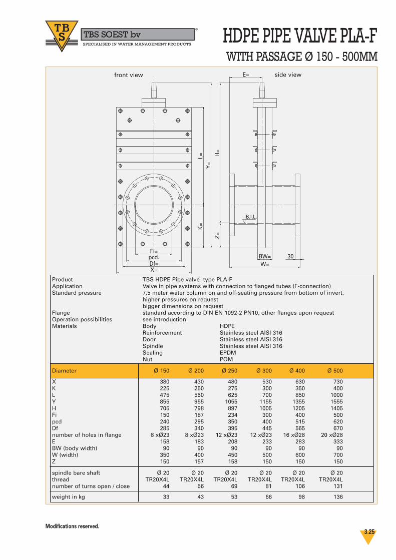
HDPE PIPE VALVE PLA-FTBS SOEST bvbbR
SPECIALISED IN WATER MANAGEMENT PRODUCTS
WITH PASSAGE Ø 150 - 500MM
Modifications reserved.3.25
Fi=
X=
BW=W=
K=
L=Y
=
E=
30pcd.Df=
Z=H
=B.I.L.
Product TBS HDPE Pipe valve type PLA-F Application Valve in pipe systems with connection to flanged tubes (F-connection)Standard pressure 7,5 meter water column on and off-seating pressure from bottom of invert.
higher pressures on requestbigger dimensions on request
Flange standard according to DIN EN 1092-2 PN10, other flanges upon requestOperation possibilities see introductionMaterials Body HDPE
Reinforcement Stainless steel AISI 316Door Stainless steel AISI 316Spindle Stainless steel AISI 316Sealing EPDMNut POM
Diameter Ø 150 Ø 200 Ø 250 Ø 300 Ø 400 Ø 500
X 380 430 480 530 630 730K 225 250 275 300 350 400L 475 550 625 700 850 1000Y 855 955 1055 1155 1355 1555H 705 798 897 1005 1205 1405Fi 150 187 234 300 400 500pcd 240 295 350 400 515 620Df 285 340 395 445 565 670number of holes in flange 8 xØ23 8 xØ23 12 xØ23 12 xØ23 16 xØ28 20 xØ28E 158 183 208 233 283 333BW (body width) 90 90 90 90 90 90W (width) 350 400 450 500 600 700Z 150 157 158 150 150 150
spindle bare shaft Ø 20 Ø 20 Ø 20 Ø 20 Ø 20 Ø 20thread TR20X4L TR20X4L TR20X4L TR20X4L TR20X4L TR20X4Lnumber of turns open / close 44 56 69 81 106 131
weight in kg 33 43 53 66 98 136
front view side view

INSTALLATION TBS SOEST bvbbR
SPECIALISED IN WATER MANAGEMENT PRODUCTS
PENSTOCK TYPE PRA - G
WALL MOUNTING
RECEIPT OF GOODSOn delivery the customer must check the goodssupplied by TBS for completeness and damage orbreakages. If the goods are not complete or aredamaged the customer must respond by return,but at the latest within 1 week after receipt ofgoods.
The customer can not claim under guarantee if:- these installation instructions are not strictly
followed.- on installation of the goods supplied the
conditions for installation do not conform with our installation manual.
- a third party has modified the goods suppliedby TBS. (The penstock forms a complete “selfcontained” unit that may not be disassembledor modified by any party other than personnelof TBS.)
Take good notice of the maximum pressure forwhich the products are designed.
PREPARING FOR INSTALLATION- The penstock is designed for mounting
against a smooth and clean wall.Smoothness of wall is in accordance with
DIN 18 202 table 3 item 7 with a maximum
deformation of 2 mm over a distance of
2 meters.
- Check the door is completely closed. If not close the door. Before installation use a straightedge to check the smoothness of the wall at the location of the penstock.
- Also check the concrete wall for small local pits and lumps so that the neoprene tape (which will be fixed to the back plate) can function properly and seal well between the frame plate and the wall.
- Moving the penstock on site has to be done carefully. Lifting the penstock must be done vertically.
INSTALLATION- Position the penstock in such manner that the
passage of the penstock is exactly in front of the outlet in the civil structure.
- Mark the two upper frame plate anchor holes on the wall. Marking can be done by pre dril-ling of the holes (through the frame).
- Remove the penstock.- Drill the two (marked) holes and mount the
anchors as instructed by the supplier of the chemical anchors. Note the time required for the hardening of the chemical substance.
- Mount the penstock by hanging it on these two anchors, after they have been fixed in place.
- Check the penstock is positioned vertically and mark the positions of all the remaining mounting holes onto the wall. Marking can be done by pre drilling. When pre drilling the holes in the horizontal
position do not damage the HDPE frame
plate, which is relatively soft and flexible.
- Remove the penstock.- Drill all the remaining holes.- Drill the holes for the wedge anchors 55 mm
deep into the concrete wall (for the countersunk head bolt M10x60).
- Place the chemical capsules in the holes and drill the anchor studs into the holes.
- Remove the resin of the chemical capsule that is coming out of the holes. Strictly follow the instructions of the supplier
of the chemical anchors. Note the time required
for the hardening of the chemical substance.
- Fix the neoprene sealing tape all round the opening and over the anchor holes at the back of the frame plate. The neoprene tape may possibly overlap at the edges of the frame.
- Make the holes for the anchors in the neo-prene tape.
- Position the penstock and put it over the anchor bars.
- Only tighten the two upper anchor bars.
- First mount the wedge anchors above and below the door as instructed by the wedge anchor supplier.
INSTRUCTIONS
Modifications reserved.3.26

INSTALLATION TBS SOEST bvbbR
SPECIALISED IN WATER MANAGEMENT PRODUCTS
- Start with the anchors in the middle above the door and work your way equally from centre to left/right side of penstock in order toprevent deformations in the frame plate. Tighten the countersunk head bolts into the wedge anchors evenly so that a good seal to the wall is obtained without deforming the frame plate.
- Do the same for the anchors below the door. - The countersunk head bolts must not protrude
as they might damage the seal on the sliding movement of the door.
- Than tighten the anchors in the guides gradu-ally one by one so that a good seal to the wallis obtained without deforming the penstock itself (frame plate and guides). Check the smoothness using a straightedge. Work your way from the bolts in the highest locations to the lowest; after tightening the bolts repeat
once again to check if the anchors are hand
tight.
INSTALLATION OF THE SPINDLE
EXTENSION (OPTIONAL)- Put the spindle extension with guide bracket
on top of the threaded spindle of the penstock.- Position the guide bracket approx. 250 mm
below the deck or upper side of the spindle extension.
- Mark the anchor holes for the guide bracket onto the wall when the spindle extension is inposition, vertical and straight, and temporarilyremove the extension.
- Drill the holes and mount the anchors as instructed by the supplier of the chemical anchors. Note the time required for the harde-ning of the chemical substance.
- Mount the spindle extension again and fix theguide bracket.
- Afterwards adjust the location of the adjustableblock on the guide bracket so that the adjustableblock is positioned at right angles to the exten-sion. Some space for moving the spindle extension will remain in the guide bracket.
COMMISSIONING
- Remove any dirt present on penstock. Especially clean the opening between the doorand the frame plate as this is a place where dirtcan easily accumulate.
- Not removing small particles as grit could
damage the seal when opening the door.
- Penstocks until dia. 400mm or square 300 mminclusive are equipped with polyacetal nut-block and for this reason never require greaseon the spindle. Only grease the spindle when the penstock is supplied with a bronze nutblock.
- Moisturize the sealant before operation /
commissioning.
- Check the functioning of the penstock by openingand closing the door.
- Do not over force the spindle. Increasing torquemeans that you have reached the end of the stroke. Do not continue operation. Over forcing the spindle can cause serious damage of the penstock
MAINTENANCE
- Check the penstock by opening and closing thedoor at least two times a year.
- Remove dirt on spindle and door. - Grease the spindle if required.
INSTALLATION OF ELECTRIC ACTUATORS
- Installation of actuators must be effected by experienced staff following the exact guide lines of the supplier of the actuator.
- TBS supplies the actuators with pre-settings ofthe required operation torque for the specific penstock.
SPECIAL CARE ABOUT CHEMICAL ANCHORS
INSTRUCTIONS
Modifications reserved.3.27
Installation diagram