Penrith City Council · Engineering Construction Specification for Civil Works Page | 2 Penrith...
84
Transcript of Penrith City Council · Engineering Construction Specification for Civil Works Page | 2 Penrith...


Penrith City Council
ENGINEERING CONSTRUCTION SPECIFICATION FOR CIVIL WORKS
UPDATES REGISTRATION
If you would like to register for updates of this specification, please email the following details to Council’s Development Engineering team at:
Name: _________________________________________________________
Organisation: _
Position: ________________________________________________________
E-mail: ________________________________________________________
Telephone: ________________________________________________________
Amendment History
Amendment Date
Council adopted working draft issue 14 October 2013
Exhibition issue 20 November 2013
Report to Council 30 November 2015
Adopted at Councils Policy Review Committee
30 November 2015
Amended 22 June 2016
Amended June 30 2017
Amended October 31 2017

CONTENTS
1. INTRODUCTION 1
2. ENGINEERING PROCEDURES FOR CONSTRUCTION OF CIVIL WORKS 2
2.1 Prior to Commencement of Works .......................................................................... 2
2.1.1 Appointment of Project Personnel .................................................................... 2
2.1.2 Consultation with Authorities and Private landowners ...................................... 4
2.1.3 Notice of Intention to Commence Works .......................................................... 5
2.1.4 Pre-Construction Site Meeting ......................................................................... 5
2.1.5 Provision for Traffic .......................................................................................... 5
2.1.6 Erosion and Sediment Control ......................................................................... 6
2.1.7 Public Liability Insurance Policy ....................................................................... 6
2.1.8 Site Fencing ..................................................................................................... 6
2.1.9 Performance Bond ........................................................................................... 6
2.2 Construction of Works ............................................................................................. 7
2.2.1 Inspections ...................................................................................................... 7
2.2.2 Disputes ........................................................................................................... 9
2.2.3 Improved Construction Methods ...................................................................... 9
2.3 Completion of Works ............................................................................................. 10
2.3.1 Compliance Documentation ........................................................................... 10
2.3.2 Final Inspection .............................................................................................. 12
2.4 Subdivision/Occupation Certificate ........................................................................ 12
2.4.1 Statement of Compliance with the Development Consent .............................. 12
2.4.2 Compliance Certificate ................................................................................... 12
2.4.3 Acceptance of Works by the Principal Certifying Authority ............................. 13
2.4.4 Subdivision Plan and 88B Instrument............................................................. 13
2.4.5 Section 73 Sydney Water and other Utility Authorities Certificate................... 13
2.4.6 Bonds ............................................................................................................ 13
2.5 Bonded Works ...................................................................................................... 13
2.5.1 Subdivisions................................................................................................... 14
2.5.2 Other Development ........................................................................................ 14
2.5.3 Contributions for Outstanding Works ............................................................. 14
2.5.4 Contributions for Outstanding Works ............................................................. 14
3. SOIL AND WATER MANAGEMENT 15
3.1 General ................................................................................................................. 15
3.2 Erosion and Sediment Control Devices ................................................................. 15
3.3 Temporary Construction Access ........................................................................... 15
3.4 Sediment Basins ................................................................................................... 16
3.5 Dust Control .......................................................................................................... 16
3.6 Maintenance ......................................................................................................... 16
3.7 Stabilisation of Disturbed Areas ............................................................................ 16
4. EARTHWORKS 18
4.1 Removal of Trees.................................................................................................. 18
4.2 Clearing and Disposal of Material ......................................................................... 18
4.3 Stripping of Topsoil ............................................................................................... 18
4.4 Unsuitable Material/Improper Works ..................................................................... 19
4.5 Embankments ....................................................................................................... 19
4.6 Grading and/or Filling of Lots ................................................................................ 19
4.7 Catch Drains ......................................................................................................... 20
4.8 Table Drains ......................................................................................................... 20
4.9 Earth Retaining Structures .................................................................................... 20
5. ROADWORKS 22
5.1 Pavement.............................................................................................................. 22
5.1.1 Boxing and Subgrade .................................................................................... 22
5.1.2 Sub-Base Course .......................................................................................... 23
5.1.3 Base Course .................................................................................................. 24
5.1.4 Roundabouts ................................................................................................. 24
5.1.5 Rural Road Shoulders .................................................................................... 24
5.1.6 Alternative Pavement Designs ....................................................................... 25
5.1.7 Recycled Pavement Materials ........................................................................ 25
5.2 Wearing Course .................................................................................................... 26
5.2.1 Single Coat Flush Seal .................................................................................. 26
5.2.2 Two Coat Flush Seal ...................................................................................... 26
5.2.3 Asphaltic Concrete (AC) ................................................................................ 26
5.2.4 Rural Access Driveways / Roadways ............................................................. 27
5.3 Classified Roads ................................................................................................... 28
5.4 Public Utility Conduits ........................................................................................... 28
6. DRAINAGE WORKS 29
6.1 General ................................................................................................................. 29
6.2 Materials ............................................................................................................... 29
6.2.1 Steel Reinforced Concrete Pipes ......................................................................... 29
6.2.2 Fibre Reinforced Concrete Pipes (FRC)............................................................... 30
6.2.3 Unplasticised PVC Pipes ..................................................................................... 30
6.2.4 Other Pipe Materials ............................................................................................ 30
6.2.5 Precast Reinforced Concrete Box Culverts .......................................................... 30
6.3 Pipe Bedding ........................................................................................................ 30
6.4 Pipe Laying & Laying of Culvert Sections .............................................................. 31

6.5 Backfilling.............................................................................................................. 31
6.6 Subsoil Drains ....................................................................................................... 32
6.7 Inter-allotment Drainage........................................................................................ 32
6.8 Road Drainage Pits ............................................................................................... 32
6.9 Open Drains .......................................................................................................... 33
6.10 Drainage Structures .............................................................................................. 34
6.11 Pipe Repairs ......................................................................................................... 34
7. CONCRETE WORKS 35
7.1 General ................................................................................................................. 35
7.2 Kerb and Gutter .................................................................................................... 35
7.3 Concrete Dish Crossings ...................................................................................... 36
7.4 Concrete Vehicular Crossings ............................................................................... 36
7.5 Concrete Footpath Paving and Pathways ............................................................. 37
7.6 Paving Units .......................................................................................................... 38
7.7 Traffic Management Decorative Thresholds .......................................................... 39
7.8 Kerb Ramps .......................................................................................................... 39
7.9 Concrete Access Driveways.................................................................................. 39
7.10 RoundAbouts ........................................................................................................ 39
8 SIGNAGE AND LINEMARKING 40
8.1 Guide Posts and Protection Fences ...................................................................... 40
8.2 Installation and Location of Road Signage ............................................................ 40
8.3 Holding Rail /”U” Rail ............................................................................................ 42
8.4 Street Name Signs ................................................................................................ 42
8. 5 Linemarking .......................................................................................................... 42
9. LANDSCAPINGWORKS 43
9.1 Grassing ............................................................................................................... 43
9.1.1 Preparation .................................................................................................... 43
9.1.2 Grassing by Seeding ...................................................................................... 43
9.1.3 Fertilisers for Seeding .................................................................................... 43
9.1.4 Sowing ........................................................................................................... 45
9.1.5 Conventional Sowing and Mulching with Bitumen .......................................... 45
9.1.6 Supply and Planting of Turf Strips .................................................................. 46
9.1.7 Care and Maintenance of Grassed Areas ...................................................... 46
9.1.8 Establishment ................................................................................................ 46
9.2 Landscaped Areas ................................................................................................ 46
9.2.1 Clearing ......................................................................................................... 47
9.2.2 Ground Improvement ..................................................................................... 47
9.2.3 Topdressing of Existing Grassed Areas ......................................................... 47
9.2.4 Trees and/or Shrubs ...................................................................................... 47

9.3 Stone Pitching and Rockwalls ............................................................................... 48
9.3.1 Stone Pitching................................................................................................ 48
9.3.2 Rock Walls ..................................................................................................... 48
9.3.3 Materials ........................................................................................................ 48
9.3.4 Foundation Preparation – Rock...................................................................... 49
9.3.5 Foundation Preparation – Soil ........................................................................ 49
9.3.6 Foundation Preparation – Inspection ............................................................. 49
9.3.7 Foundation Depth .......................................................................................... 49
9.3.8 Placement of Rock ......................................................................................... 49
9.3.9 Backfill – Materials ......................................................................................... 49
9.3.10 Backfill –Compaction ..................................................................................... 50
9.3.11 Appurtenant Structure .................................................................................... 50
9.3.12 Drainage – Surface Runoff ............................................................................. 50
9.3.13 Drainage – Subsoil Drain ............................................................................... 50
10. GLOSSARY 51
11. STANDARD DRAWINGS 55

ATTACHMENTS
Attachment 1 – Contractors Check List

Engineering Construction Specification for Civil Works Page | 1
Penrith City Council
1. INTRODUCTION This Specification has been prepared to provide engineering construction requirements for the subdivision and development of land within the Penrith City Council area. This Specification should be read in conjunction with Council’s Engineering Design Guidelines.
The aim of the Specification is to ensure that infrastructure associated with any development is constructed to be safe, serviceable, economical to maintain and meets community expectations.
Applicants should be aware that each development is required to be treated on its merits, and that approval is dependent on the overall impact of the development and not solely on compliance with minimum engineering standards.
Nothing in this Specification is to be construed as limiting, in any way, Council's rights to impose differing conditions when approving development proposals, nor limiting the discretion of Council's Engineering Services or City Works Managers or a nominated representative to vary any necessary engineering requirements in respect of a particular development or Council project, having regard to good engineering practice.
Any construction procedure or material that is not covered by this Specification shall only be permitted where explicit written approval has been granted by Council’s Engineer. This may require the submission of certification or compliance reports where appropriate.
Where work to be undertaken is not covered by this Specification, the relevant Australian Standard, NATSPEC (AUSPEC), RMS Specification or industry best practice shall be deemed to apply.
This Specification will be revised periodically to embrace new ideas and technologies and to co-ordinate with updated Council planning and engineering policy.
Where discrepancies exist between this Specification and the Adopted “Design Guidelines for Engineering Works for Subdivisions & Developments – 1997”, this Specification shall take precedence.
For further clarification contact Council’s Development Engineer Section.
All standards and specifications referred to in this document are to be the current issue.

Engineering Construction Specification for Civil Works Page | 2
Penrith City Council
2. ENGINEERING PROCEDURES FOR CONSTRUCTION OF CIVIL WORKS
2.1 PRIOR TO COMMENCEMENT OF WORKS
Before any works are to commence, it is the responsibility of the Applicant to ensure that any engineering approvals required, e.g. Construction Certificate, Roads Act Approval, Local Government Approval etc. have been obtained. A copy of the engineering approval and stamped approved Engineering Drawings shall be kept on site at all times. Refer to Council’s Engineering Design Guidelines for further information in relation to obtaining approvals.
For all works that are to be undertaken within a dedicated public road, or where otherwise conditioned on the development consent, the Applicant shall ensure that a performance bond has been lodged with Penrith City Council in accordance with its Bond Policy.
2.1.1 APPOINTMENT OF PROJECT PERSONNEL
It should be noted clearly by all parties that project personnel are contracting to the Developer/Applicant and not to Council. It is the responsibility of the Applicant to ensure that all works are carried out in a sound, efficient and workmanlike manner, in accordance with sound engineering practice and principles, and are completed in accordance with the approved Engineering Drawings and Specifications.
Final approval of the works rests with the Council, on the assurance of Council’s Engineer or the accredited certifier that the Engineering Drawings and Specifications have been complied with, and the construction satisfactorily completed.
If irregularities occur and are not rectified to the satisfaction of Council’s Engineer or the accredited certifier or if work is covered before an inspection has been made, no guarantee is given that the works will be accepted when application is made.
Project Manager
For developments involving complex engineering issues it is recommended that the Applicant engages the services of an experienced Project Manager. It is the Project Manager’s responsibility to ensure the works are carried out in accordance with the development consent and to co-ordinate the delivery of the works.
Once the Project Manager has been engaged, Council's officers will have only one contact that is co-ordinating the progress of the development. Time delays often arise where inexperienced Applicants try to share the project management role.
The Project Manager must be readily available and have sufficient authority and ability to discuss and resolve problems and act as the principal contact with Council.
A Developer who chooses to adopt this role must be aware that Council does not become involved in co-ordinating activities or giving advice beyond Council responsibilities.

Engineering Construction Specification for Civil Works Page | 3
Penrith City Council
Principal Certifying Authority
The Applicant must appoint a Principal Certifying Authority (PCA) for each development project. The PCA must be appointed a minimum of 2 days before the commencement of works.
Council must be appointed as the Principal Certifying Authority for subdivisions, unless an Accredited Certifier is permitted to act in this role under the Environmental Planning & Assessment Act, or where permitted by an Environmental Planning Instrument.
An application form to nominate Council as the Principal Certifying Authority can be located on Council’s website.
Certifying Authority
Council or an Accredited Certifier must be appointed to issue a Construction Certificate for proposed subdivision and development works, and Council or an Accredited Certifier must be appointed to undertake Compliance Inspections for subdivision and development works. These roles are mutually exclusive and need not be carried out by the same Certifying Authority.
The Certifying Authority for the compliance inspections will inspect the work to ensure the contractor carries out the work in accordance with the approved Engineering Drawings and Council's Specification. Any critical stage inspections nominated by the PCA will also need to be carried out by the Certifying Authority.
Accredited Certifiers do not have authority to carry out inspections for works on Public Roads where approval for the works is granted pursuant to the Roads Act, unless authorised by the Roads Authority.
Superintendent/Supervisor
The Project Manager is to nominate a person to supervise all works on site. It is not the Certifying Authority’s role to supervise construction. The Superintendent/Supervisor is to liaise with the Project Manager regarding any instruction by the Certifying Authority. It is the Superintendent/Supervisor’s role to ensure that all works are carried out in accordance with the contract, approved Engineering Drawings, Council’s Specification, relevant legislation and engineering best practice.
Principal Contractor
The Project Manager must appoint a Principal Contractor for the works who must be the holder of a contractor licence (if any residential building work is involved), and notify the Principal Certifying Authority of any such appointment.
It is the Principal Contractor’s role to ensure that all works are carried out in accordance with the contract, approved Engineering Drawings, Council's Specification, relevant legislative requirements and engineering best practice.
The Principal Contractor is responsible for the actions of any sub contractors on the site. Any instruction issued by Council’s Engineer or the accredited certifier to a sub contractor is considered to be an instruction issued to the Principal Contractor. It is the Principal Contractor’s responsibility to ensure that procedures are in place on site to ensure that instructions to the sub contractor are directed through appropriate channels.

Engineering Construction Specification for Civil Works Page | 4
Penrith City Council
The Principal Contractor must ensure that they comply with their responsibilities under the Work Health and Safety Act. All contractors must have a current Workers Compensation Insurance Policy for all employees as required by Statute.
2.1.2 CONSULTATION WITH AUTHORITIES AND PRIVATE LANDOWNERS
Compliance with Development Consent conditions may require payments, approvals, authorisations or works under the control of Utility Authorities, State and Federal Authorities or Private Landowners. It is the responsibility of the Project Manager to make enquiries and meet any additional requirements to enable compliance with the Development Consent and relevant legislation.
Where conditions have been imposed by other authorities or private landowners the works are required to be carried out in accordance with their requirements and Council’s.
The Developer is responsible for obtaining any permits and licences, meeting inspection and works standards and gaining final approval of relevant Authorities and private landowners.
Principal Contractors are to ensure that they hold all relevant documentation regarding requirements from other Authorities and private landowners before commencing any site activities.
Utility Authorities
It is essential that Utility Authorities are consulted and that information is obtained regarding the existence and location of utility mains and installations. Prior to the commencement of the works the Applicant shall ascertain from the appropriate Public Utility Authority, Dial Before You Dig (1100), and/or the Council, the position and depth of all existing services which may be interfered with during the excavation and/or construction of the works. The Applicant shall take every precaution to avoid damage to any utility service within, or adjacent to, the limits of the works and will be held responsible for any such damage caused by him or his agents, directly or indirectly.
If, during the conduct of the works, any alteration or damage to existing services is occasioned, it will be the responsibility of the Applicant to make the necessary arrangements for rectification with the appropriate authority. All alterations and repairs will be carried out to the requirements of the appropriate authority and written clearance is to be obtained from the relevant authority prior to the final inspection.
Where required, water, sewer, electricity supply, street lighting, communication and, gas services shall be provided in accordance with the relevant Authority requirements and any other conditions set by Council.
Utility drawings shall be provided to the Principal Certifying Authority and Certifying Authority by the principal contractor prior to the Commencement of Works.
State and Federal Authorities
There is a number of State and Federal Authorities which have control over development works in various ways. A consent, licence, permit, permission or form of authorisation may be required by these authorities. These Authorities may hold powers to impose penalties, halt works or require restoration works.
Irrespective of any Council requirement or absence thereof, all work shall be carried out in accordance with the requirements of these Authorities and related Legislation and Regulations.

Engineering Construction Specification for Civil Works Page | 5
Penrith City Council
The Project Manager is generally responsible for ensuring all necessary approvals are obtained and that any requirements are conveyed to his Principal Contractor through the provision of relevant plans and documents.
Private Landowners
Private property is often directly affected by development related works. It is the responsibility of the Developer to obtain landowners’ consents to enter onto private lands to undertake works. The Applicant or his representative(s) shall not commit any act of trespass and shall effectively protect all adjoining properties and owners thereof against any loss, damage or injury that may occur through the carrying out of the works.
In such cases Council may require that a deed of agreement protected by a caveat be entered into between the Developer, the Landowner and Council to ensure the creation of easements, rights of way or restrictions as to user.
Where an adjoining owner’s consent or right-of-entry was obtained for work on adjoining lands, the Applicant must obtain a written clearance from that adjoining owner confirming that they are satisfied with the completed works, and a copy of such written clearance shall be forwarded to the PCA.
2.1.3 NOTICE OF INTENTION TO COMMENCE WORKS
A minimum of 2 days before commencement of works, the developer must notify to the Council, and the Principal Certifying Authority (if that is not the Council), of intention to commence works.
The notice of intention to commence work must be in writing and shall be accompanied by the following documentation as relevant or as described in the Development Consent.
Sediment and Erosion Control Plan
Traffic Control Plan/Traffic Management Plan
Application for the use of alternative or recycled materials not covered by this
Specification
Management of the Worksite Plan
Road Naming Application
Street Tree Plan
Pavement Design
Street Lighting (forms for Council’s acceptance)
Proof of all contractors’ Public Liability Insurance
2.1.4 PRE-CONSTRUCTION SITE MEETING
Prior to the Commencement of Works the Project Manager shall arrange for and co-ordinate a site meeting including the Principal Certifying Authority, Certifying Authority, Superintendent/Supervisor, Principal Contractor and Council. The aim of the meeting is to review the Engineering Drawings on site and identify any constraints or issues that require further consideration. The site meeting is an opportunity to raise any issues with the Engineering Drawings or clarify conditions of consent with all parties present and handover of Council’s latest specifications.
2.1.5 PROVISION FOR TRAFFIC
Where applicable, the Applicant shall provide a Traffic Management Plan and/or any Traffic Control Plans to Council prior to commencement of works. The Traffic Management Plan shall consider site access and the route in which construction traffic will travel to and from the site.

Engineering Construction Specification for Civil Works Page | 6
Penrith City Council
In respect of construction work adjoining existing streets or pavements, the Applicant shall provide proper fencing, barriers, signs, lighting and supervision of all work and such temporary roadwork and footways, as may be necessary for the accommodation and protection of pedestrians, vehicles, the public and animals.
Appropriate traffic warning signs shall be erected in accordance with the requirements of AS1742 (2014) – “Manual of Uniform Traffic Control Devices” and/or RMS Work Near Traffic “Traffic Control at Work Sites Version 4”.
If necessary, the Applicant shall provide for traffic by its diversion to an alternative route approved by Council’s Engineer, or by the formation of side tracks alongside the work, or by the construction of one-half of the road at a time, leaving the other half available for traffic.
The temporary closing of a road and/or the provision of a temporary road shall be undertaken in accordance with the provisions of the Local Government Act and Roads Act. All costs involved shall be borne by the Applicant. It is recommended that early contact be made with Council’s Engineer for any road closure proposal to ensure all necessary approvals are obtained, including that of the Local Traffic Committee where necessary.
All Traffic Control Plans must be prepared by a suitably qualified contractor with the appropriate training and certification from the Roads & Maritime Services (RMS).
2.1.6 EROSION AND SEDIMENT CONTROL
Prior to Commencement of Works, sediment and erosion control measures shall be installed in accordance with Part 3 of this Specification.
Prior to undertaking any further works, the sediment and erosion control measures are to be inspected by the Certifying Authority for compliance with the approved sediment and erosion control plan.
2.1.7 PUBLIC LIABILITY INSURANCE POLICY
Contractors or sub-contractors engaged on Development or Subdivisional Works or when working in or connecting to public roads shall obtain Public Liability Insurance for a minimum cover value of $20million before commencing construction. The policy shall specifically indemnify Council from all claims arising from the execution of works.
A copy of the Public Liability Insurance policy shall be forwarded to Council prior to commencement of works noting the policy expiration date. The period of the policy must be sufficient to complete the subject works.
2.1.8 SITE FENCING
Each Construction / Development site shall be adequately fenced in accordance with the requirements of Work Cover NSW.
2.1.9 PERFORMANCE BOND
Prior to the issue of a Roads Act approval or Construction Certificate a Performance Bond may be lodged with Council to ensure the satisfactory completion of the works. The bond may be called up if works are not completed to the satisfaction of Council. At the completion of works the Performance Bond will be refunded upon lodgement of a Maintenance Bond. The Maintenance Bond will be held for a period of 12 months to cover the defects liability period. The value of the Performance Bond and Maintenance Bond is determined in accordance with Council’s adopted fees and charges.

Engineering Construction Specification for Civil Works Page | 7
Penrith City Council
2.2 CONSTRUCTION OF WORKS
This section sets out requirements to be considered and monitored during the construction of the works. It is the responsibility of the Applicant to ensure that the construction site is kept in a safe and tidy manner at all times, including where the site interfaces with public roads or lands. Security safety fencing and any traffic control measures are to be continually maintained to ensure the site is safe to the public and to prevent unauthorised vehicle and pedestrian traffic from entering the site. The ongoing maintenance of sediment and erosion control and dust control measures shall be monitored at all times in accordance with Section 3 of this Specification.
2.2.1 INSPECTIONS
All civil works carried out as part of the subdivision or development works shall be inspected by Council’s Engineers or the accredited certifier for compliance with the Development Consent, approved Engineering Drawings and Council’s Specification.
It should be noted that inspections by Council’s Engineer or the Accredited Certifier do not relieve the Applicant of the responsibility to supervise, or arrange the supervision of, the work as indicated. An inspection by Council’s Engineer or the accredited certifier is for the purpose of enabling certification to the Council, when the works have been completed, that they have been properly carried out in accordance with the approved Engineering Drawings and Council’s Specification, and they are in a satisfactory state for the Council to take them over. Consequently, any defects that develop before the work is finally accepted by the Council shall be rectified, even though the defective work may have been previously inspected by Council’s Engineer or the Accredited Certifier. Failure by the Applicant to comply with all reasonable requests and directions from Council’s Engineer or the accredited certifier will be sufficient reason for the Council to withhold final acceptance of the works.
Where inspections are required outside normal Council working hours, it will be necessary to request such inspections in writing to Council or the accredited certifier and will be conditional upon the Applicant accepting all costs involved in Council’s Engineer or the Accredited Certifier undertaking such inspections.
Twenty four hours (one working day) notice must be given to Council’s Engineer or the Accredited Certifier for any inspection and subsequent work is not to be carried out until after the inspection. A Certificate of Inspection will be issued following each inspection by Council’s Engineer noting whether or not the works have been approved.
The following schedule contains what Council requires as mandatory inspections. It is the responsibility of the Project Manager/Applicant to ensure that mandatory inspections are carried out in accordance with the schedule.
Soil Erosion and Sediment Control
Implementation of erosion and sediment controls, Construction of major controls (i.e. basins, gabions, mattresses, shot-creting etc), Internal sediment/pollution control devices, Removal of sediment basins/fencing etc, Revegetation and stabilisation of disturbed areas, and Final inspection.
Traffic Control
Implementation of traffic control, Maintenance of traffic control during works, and

Engineering Construction Specification for Civil Works Page | 8
Penrith City Council
Removal of traffic control.
Bulk Earthworks / Filling
Embankments as per Section 4.5
Construction of Drainage Works (including inter-allotment drainage)
Sub soil pipes in the trench before back fill of aggregate Pipes before backfilling (alignment, trench excavation, bedding and pipe class), Bedding material compacted to haunch Trench backfill compaction, Pit bases and headwall aprons, Pit walls/wing walls/head walls, Pipe to pre-fabricated pit connections Internal inspection of pipeline Concrete pit tops/ lintels Connection to existing system, Tailout works, and Final inspection.
Construction of Road Pavement
Boxing, including depth and profile, Sub-grade proof roll, Sub-soil drainage, Sub-base proof roll for kerb and gutter, Sub-base proof roll between kerbs (layers not exceeding 200mm), Dish crossings prior to pouring, Formwork and reinforcement for concrete pavements, Kerb during laying, including provision of roofwater outlets, laybacks and pram ramps, Segmental paving units, Sub-base depth and profile, Kerb alignment, Base course proof roll, Base course profile, One coat flush seal, 1st layer of AC and wearing course, Kerb final, Final inspection.
Provision of Street Furniture
Street furniture (including street signs, guideposts, guardrail etc), and Erection of fencing adjoining public/drainage reserves.
Vehicular Crossings
Laybacks,
Vehicular Crossings.
Engineering Construction Specification for Civil Works Page | 9
Penrith City Council
Verge Works
Footpath trimming and turfing (to ensure 4% fall), Formwork, including reinforcing jointing etc, for cycleways, path paving and pram
ramps, Foothpath paving units Inspection of sub-grade for all concrete Service adjustments, Footpath alignment, and Final inspection.
Other Structural Works
Bases, Footings, Formwork, including reinforcing, jointing etc, Final inspection.
Stormwater Quality Control
Installation of stormwater quality control devices, Steel and formwork for concrete structures, Installation of subsoil drainage and filter materials, and. Final inspection (includes inspection of any GPTs and specialist landscaping).
Final Inspections
Overall final inspection. Inspection of first layer of AC and inspection of defect repairs, crack sealing prior to
placing final wearing course Prior to final inspection the Principle Contractor must certify that the works have been
completed satisfactorily. This certification must include the completion of the “Final Inspection” check list at Appendix ‘A’.
2.2.2 DISPUTES
Any dispute with an instruction issued by the Certifying Authority or interpretation of Engineering Drawings and Council’s Specification shall be addressed by the Principal Certifying Authority, Certifying Authority, Superintendent/Supervisor, Project Manager and Principal Contractor prior to acting on the terms of the instruction.
2.2.3 IMPROVED CONSTRUCTION METHODS
Council encourages the consideration of new and improved construction practices and techniques. Any proposed use of new construction practice or techniques shall be discussed with and approved by Council’s Engineer or the Accredited Certifier prior to proceeding.
Trenchless techniques can have advantages where appropriate for the provision of new installations. Such techniques include micro tunnelling, directional drilling, pipe jacking, impact moling and boring. Requirements for space for plant operation may be critical to the use of these methods.
Engineering Construction Specification for Civil Works Page | 10
Penrith City Council
2.3 COMPLETION OF WORKS
When the Project Manager considers that the works have been completed, they will arrange for the lodgement of all necessary compliance documentation for the review of the Certifying Authority and make arrangements for a final inspection.
2.3.1 COMPLIANCE DOCUMENTATION
The following documentation must be reviewed by the Certifying Authority prior to the issue of a Compliance Certificate attesting to the satisfactory completion of the works. If the review of this documentation identifies any non compliances then these matters shall be brought to the attention of the Principal Certifying Authority for further action. One hard copy and one electronic copy of all compliance documentation must be submitted to Council.
Pipe repairs that have been endorsed by Council Engineers must be detailed and included in the subdivision compliance documentation. The Work-As-Executed plans shall clearly note the location of any repaired pipeline. Additional documentation shall be included that demonstrates testing documentation of the repair product and the applicators warranty that the repairer has guaranteed and both meet the pipelines minimum design life of 100 years.
Works-As-Executed (WAE) Plans
Following the completion of engineering works of a subdivision or development, WAE plans are required to be prepared and signed by a Registered Surveyor noting the survey company, Surveyors name and date of survey. The WAE plans and WAE Checklist are to be submitted to the Certifying Authority prior to the final inspection.
The WAE plans shall indicate:
Confirmation of all civil components as constructed Invert levels of all drainage pipes and/or box culverts (within pits), at entrance and exit Location and size of pipes, and/or box culverts and subsoil lines Pipe grades Location of all pits Location of service conduits Verge and road widths at all TP’s, centre of curves, beginning and end of construction,
at 50 metre intervals on straights and where the width varies by more than 10% from approved width
Footpaving widths Road centreline levels and kerb levels at all TP’s, crests, sags, end of construction,
and elsewhere at 50 metre intervals. Road cross sectional information notation on plans as to whether road surface levels were taken on first or final layer of
asphalt Location of vehicle entries and pram ramps Location and depth of slope junctions and pits relative to property boundaries on inter-
allotment drainage lines Site regrading details – finished surface levels and natural surface levels prior to
regrading, at lot boundaries, centre of front and rear boundaries, 12 metres from front boundary on sides and centre of the lot
Contour depth of fill plans with depths in 0.3m increments indicated by cross-hatching or shading
Details of all variations from the approved design Signage and linemarking

Engineering Construction Specification for Civil Works Page | 11
Penrith City Council
The WAE plans must be prepared on a stamped (original) copy of the approved plan, and all WAE information notated in red. The original notated plan shall be forwarded to Council.
CCTV
At the completion of all works, CCTV footage of all stormwater drainage infrastructure and an inspection report in Sewrat format shall be undertaken and submitted to the Certifying Authority. Pipelines are to be clean and free of debris and silt. CCTV of dirty silted lines will not be accepted. The CCTV inspection shall be undertaken following stabilisation of the site and cleaning of the system. Where defects are identified, repairs shall be performed in accordance with the manufacturer’s recommendations. Defects shall be notified to Council / PCA for approval of repair procedures prior to any repairs being made. Repairs are to be made to the satisfaction of the Council and revised CCTV footage and inspection report submitted to demonstrate rectification works have been completed. All repairs are to have certification of 100 years design life.
Geotechnical Report
The final submission requires lodgement of a geotechnical report prepared by a practising geotechnical engineer.
The report is to detail the matters relating to road pavement compaction, lot filling, earthworks and lot classification and compliance with Council’s Specification. The report is to be accompanied by the Geotechnical Engineer Certificate certifying that the required compactions were achieved in accordance with Council’s Specification and/or relevant Australian Standards.
A lot fill diagram must be provided where lots have been filled. The diagram will show fill areas in different colours or hatching for depths of fill in 300mm increments. The diagram will apply to all lots that have been filled in excess of 300mm.
Easement Certificates
The final submission requires lodgement of a Surveyor's Certificate from a Registered Surveyor. This certificate will certify that all pipes, structures and services are located within their respective easements.
Material Compliance Certificates
Material Compliance Certificates for all road pavement materials will be required to be submitted prior to issue of the Subdivision Certificate or upon completion of the works.
All materials shall comply strictly with Council’s Specification or Council’s written approval of alternate materials.
Engineer's Certificates
Where structural work has been undertaken on a project, a certificate from a suitably qualified Registered Structural Engineer must be lodged, certifying the adequacy of the structure.
Slope Junction Plan (Inter-allotment Drainage)
A slope junction plan indicating location, depth and off-sets from boundaries of all slope junctions shall be prepared by the project engineer/surveyor and submitted to Council.
Street/Public Lighting and Utility Installations

Engineering Construction Specification for Civil Works Page | 12
Penrith City Council
Utility Authority Compliance Certificates are to be provided demonstrating that all necessary services have been installed to the standards and requirements of the respective authority.
Adjoining Owners Clearance
Where work has been carried out on adjoining properties, a written clearance from the respective owners stating their satisfaction with completed works must be lodged with the final document submission.
2.3.2 FINAL INSPECTION
Following review of the compliance documentation including the “Final Inspection” checklist, the Certifying Authority shall undertake a final inspection of the works. Any defects or non compliances identified in the review of compliance documentation or during the inspection are to be rectified prior to the issue of a Compliance Certificate certifying that the works have been satisfactorily completed.
Where Council is not the Certifying Authority it is recommended that Council is invited to participate in the final inspection so that any issues are identified at the same time as those raised by an independent Certifying Authority. It is advised that where Council is the Principal Certifying Authority for subdivisions and other development a final inspection shall be undertaken prior to the issue of any Subdivision/Occupation Certificate.
Note: The Final Inspection Certificate issued by the Certifying Authority at the time of inspection of s68 (EP&A Act) or s138 Roads Act) works is not the final sign-off. Final sign-off does not occur until a formal letter from Council’s Development Engineering Unit is issued to the Applicant.
2.4 SUBDIVISION/OCCUPATION CERTIFICATE
Prior to the issue of a Subdivision/Occupation Certificate the Principal Certifying Authority shall be satisfied that all matters specified in the EP&A Act and the development consent have been met. In this regard any application for a Subdivision/Occupation Certificate shall be accompanied by the following documentation:
2.4.1 STATEMENT OF COMPLIANCE WITH THE DEVELOPMENT CONSENT
The development consent needs to be reviewed regularly during the works. The application for a Subdivision/Occupation Certificate shall be accompanied by a Statement of Compliance detailing how each condition of the development consent has been met.
2.4.2 COMPLIANCE CERTIFICATE
Prior to the issue of a Subdivision/Occupation Certificate, where Council is the PCA and an Accredited Certifier has undertaken inspections, Council will require the submission of a final Part 4A Compliance Certificate, with one hard copy and one electronic copy of supporting compliance documentation, including WAE plans, as required by Council’s Specification.
Where Council is not the Principal Certifying Authority the same documentation shall accompany the prescribed notice of issue of the Subdivision/Occupation Certificate.
It is the responsibility of the Certifying Authority to ensure that all works have been carried out in accordance with the development consent, approved Engineering Drawings and Council’s Specification. The final Compliance Certificate shall clearly certify that these requirements have been met. The final Compliance Certificate shall not be issued if any works, other than works that are to be bonded, are outstanding.

Engineering Construction Specification for Civil Works Page | 13
Penrith City Council
2.4.3 ACCEPTANCE OF WORKS BY THE PRINCIPAL CERTIFYING AUTHORITY
The Principal Certifying Authority must undertake a final inspection of the subdivision or development works. Prior to the issue of a Subdivision Certificate / Occupation Certificate any deficiencies identified with the works must be rectified to the satisfaction of the Principal Certifying Authority.
2.4.4 SUBDIVISION PLAN AND 88B INSTRUMENT
Any subdivision plan and/or 88B Instrument must be consistent with the plan and conditions approved with the development consent. The subdivision plans and 88B shall indicate:
Road Names in accordance with Council’s “Road Naming Policy”. A copy of the policy can be found on Council’s website.
All necessary legal instruments required to effect the development consent
2.4.5 SECTION 73 SYDNEY WATER AND OTHER UTILITY AUTHORITIES
CERTIFICATE
All subdivision applications in the Penrith Local Government Area must be accompanied by a s73 Certificate from Sydney Water as required by the EP&A Act.
Compliance Certificates from other Utility Authorities may be required by conditions of the development consent.
2.4.6 BONDS
Prior to the issue of Subdivision Certificate/Occupation Certificate the following bond types are to be lodged, as required by Council’s Engineer
Maintenance Asphaltic Concrete – final layer Outstanding Works (where permitted by Council’s Engineer or the Accredited Certifier)
Council will not accept Outstanding Works Bonds for works on private lands or land not in Council’s future ownership.
All bonds must be in accordance with Council's adopted Fees and Charges..
Bond amounts must be verified by Council. Confirmation of bond amounts will be undertaken by Council upon written request.
2.5 BONDED WORKS
The Developer’s obligations will be complete when the defects liability period has elapsed and all bonds have been returned.
A request for the release on a Maintenance bond shall be supported by new CCTV footage (maximum 4 weeks old) of all stormwater drainage infrastructure and an inspection report in Sewrat format shall be undertaken and submitted to the Certifying Authority. Pipelines are to be clean and free of debris and silt. CCTV of dirty silted lines will not be accepted. Defects shall be notified to Council / PCA for approval of repair procedures prior to any repairs being made. Repairs are to be made to the satisfaction of the Council and revised CCTV footage and inspection report submitted to demonstrate rectification works have been completed. All repairs are to have certification of 100 years design life.
Engineering Construction Specification for Civil Works Page | 14
Penrith City Council
2.5.1 SUBDIVISIONS
Upon the issue of a Subdivision Certificate the works will enter the Maintenance Period. During this period any defects which become evident will be the responsibility of the Applicant to rectify. The Maintenance Period is a minimum of 12 months from the issue of the Subdivision Certificate. The Maintenance Period may be extended by the Council subject to consideration of the development status and for the purposes of further monitoring any matters that become evident during this period. An inspection shall be undertaken by Council at the end of the Maintenance Period, with any defects identified to be rectified to the satisfaction of Council’s Engineer and a satisfactory inspection by Council. At the end of the Maintenance Period, following the rectification of any defects, and a satisfactory inspection by Council, bonds will be released and Council will issue a formal acceptance of the works.
Letter of Undertaking in Lieu of Bond
2.5.2 OTHER DEVELOPMENT
Following the Final Inspection by the Principal Certifying Authority the works will come under a Maintenance Period of at least 12 months. The Maintenance Period may be extended by the Council subject to consideration of the development status and for the purposes of further monitoring any defects that become evident during this period. At the end of the Maintenance Period, following the rectification of any defects, bonds will be released and Council will issue a formal acceptance of the works.
2.5.3 CONTRIBUTIONS FOR OUTSTANDING WORKS
In limited circumstances Council may accept a monetary payment for outstanding works, in lieu of a bond, to discharge the developer of their obligations. An application to make a monetary payment in lieu of providing a bond shall be made in writing. If agreed to, any such payment will be subject to a quotation by Council. The quotation shall allow for relevant administration costs and a surcharge allowing for indexation where works will be delayed.
2.5.4 CONTRIBUTIONS FOR OUTSTANDING WORKS
Additional CCTV may be required at the end of defects inspection as directed by Council.

Engineering Construction Specification for Civil Works Page | 15
Penrith City Council
3. SOIL AND WATER MANAGEMENT Suitable erosion and sediment controls shall be provided and maintained by the contractor where shown on the approved Engineering Drawings or where directed by Council’s Engineer or the Accredited Certifier. Such controls shall be in accordance with the requirements of the Protection of the Environment Operations Act, these Specifications and the Office of Environment and Heritage’s “Managing Urban Stormwater: Soils and Construction – Volume 1” (commonly referred to as the Blue Book).
3.1 GENERAL
Perimeter control measures shall be placed prior to or in conjunction with the first phase of earthworks. Construction shall be phased if directed by Council’s Engineer or the Accredited Certifier so that land disturbance is confined to areas of workable size. This will limit the duration for which disturbed areas are exposed to erosion. Stabilisation measures shall be applied on the first disturbed section before the next section is opened up.
Topsoil stockpiles shall be located outside hazard areas such as drainage depressions and shall have appropriate erosion and sediment control devices installed around the perimeter.
Where site regrading or filling is being undertaken, surface water shall be directed away from the face of batters.
All areas not subject to construction works shall be retained free from disturbance or damage during the works. Should these areas become disturbed or damaged they shall be reinstated at no cost to the Council.
3.2 EROSION AND SEDIMENT CONTROL DEVICES
Where shown on the approved Engineering Drawings or otherwise specified, erosion and sediment control devices shall be constructed and maintained. Unless the device is a permanent structure, it shall be removed when the areas above it have been stabilised. The control devices shall be constructed in the locations shown on the Drawings unless an alternative location is directed by Council’s Engineer or the Accredited Certifier.
Erosion and sediment control devices shall be constructed and maintained in accordance with “Managing Urban Stormwater: Soils and Construction – Volume 1”, and may include, but not be limited to:
Diversion channels/banks Level spreader systems Straw bale barriers Gravel outlets Rip Rap / Stone Pitching Sediment traps for surface and kerb inlets and culverts Filter dams Sediment basins
3.3 TEMPORARY CONSTRUCTION ACCESS
A temporary construction exit from the site is to be provided to shake off site material from vehicles exiting onto public roads to the satisfaction of Council’s Engineer or the Accredited Certifier Generally this shall consist of a tyre wash station and precast or prefabricated steel “cattle grid” type shaker and/or pad of coarse crushed rock, crushed slag or gravel (75mm to 150mm range) having a minimum depth of 200mm, a minimum length of 25m and a width as

Engineering Construction Specification for Civil Works Page | 16
Penrith City Council
nominated on the Drawings. Any such device shall be maintained and/or replaced as directed by Council’s Engineer or the accredited certifier.
3.4 SEDIMENT BASINS
Sediment basins, where specified, shall be constructed to the details shown on the drawings and in accordance with “Managing Urban Stormwater: Soils and Construction – Volume 1”. The basin shall be constructed as the first phase of the earthworks operation.
3.5 DUST CONTROL
Appropriate dust control methods are to be employed to prevent the loss of soil via airborne dust. Prompt revegetation or mulching of disturbed areas will reduce surface and airborne movement of sediment.
Other methods of dust control include:
The retention of existing trees and shrubs to act as a windbreak The control of traffic movement over the construction site Wetting the site surface is an emergency treatment which can be repeated as
necessary (control of sediment laden runoff from over-watering must be closely monitored).
Council’s Engineer or the Accredited Certifier may stipulate that work cease until such time as any particular dust nuisance has been appropriately controlled.
3.6 MAINTENANCE
All sediment and erosion control devices shall be maintained in accordance with the approved erosion and sediment control plan and “Managing Urban Stormwater: Soils and Construction – Volume 1”, throughout the Construction and Maintenance Period or until such time as the area has been stabilised and Council’s Engineer or the Accredited Certifier directs that the device be removed.
The Contractor shall inspect the devices after each storm for structural damage or clogging by silt and other debris and make prompt repairs or replacement. All sediment deposited within ponded areas shall be periodically removed to a disposal area. Gravel or other filter materials shall be cleaned and restacked or replaced so as to maintain effective performance.
Sediment basins shall be flocculated and dewatered following major storm events so as to maintain storage capacity. Water reclaimed from sediment basins may be used back on the development site and may not be disposed of in the drainage system.
In the case of the temporary construction exit, the contactor shall undertake weekly or daily surface cleaning by road broom or equivalent, to remove all build up of foreign material to the satisfaction of Council’s Engineer.
To control bank growth and to maintain healthy ground cover in channels and on banks, mowing shall be undertaken. All costs associated with this Clause shall be borne by the Applicant.
3.7 STABILISATION OF DISTURBED AREAS
Stabilisation of disturbed areas shall be in accordance with the following and “Managing Urban Stormwater: Soils and Construction – Volume 1”.

Engineering Construction Specification for Civil Works Page | 17
Penrith City Council
Where practical the following principles shall be applied for the control of erosion and sedimentation, and shall be undertaken within seven (7) days of the areas being disturbed:
Stabilisation of denuded areas. Stabilisation of the area over all stormwater drainage lines and sewer mains not within
road reserves. All temporary earth diversion channels/banks and sediment basin embankments shall
be seeded with approved seed mix.
At the completion of works, all disturbed areas are to be grassed in accordance with Section 9.1 of this Specification and verge areas are to be turfed for the full width from back of kerb to property boundary (excluding the hard paved areas)
All stabilisation measures shall be undertaken prior to the final inspection by Council’s Engineer or the accredited certifier
Engineering Construction Specification for Civil Works Page | 18
Penrith City Council
4. EARTHWORKS 4.1 REMOVAL OF TREES
The Applicant is advised that no trees are to be removed without Council permission.
Engineering Drawings are to show all trees, and shall clearly define any trees proposed for removal. (Penrith City Council’s Tree Preservation Order defines a Tree as “any tree or other vegetation having a height of three (3) metres or more or a trunk circumference exceeding 300mm at 400mm above ground level”).
Removal of trees is limited to those approved for removal in the Development Consent. Other trees that are directly affected by road and/or drainage construction or as specified herein will require special approval prior to removal.
Trees which, in the opinion of Council, are considered to be dangerous or may damage any part of the road, proposed road or public place, drainage structure of any public utility installation, or may affect visibility, shall be removed or trimmed as directed by Council’s Engineer or the Accredited Certifier at no cost to Council.
The removal of trees in fill areas may only be undertaken with the express permission of Council’s Engineer or the Accredited Certifier, and will be dependent upon the depth of fill and/or the type of tree.
Trees and/or shrubs to be retained are to be adequately protected at all times and particular care shall be taken to avoid damage to the roots, trunks and branches.
The removal of any other tree is to conform to Penrith City Council’s Tree Preservation Order.
4.2 CLEARING AND DISPOSAL OF MATERIAL
For the full area of the site specified or shown on the Engineering Drawings the prescribed materials, being fences, concrete and/or brick foundations and/or floors, structures of all descriptions, trees, shrubs, scrub, stumps, logs, boulder and roots – except those fences, structures, trees, shrubs and/or items which Council’s Engineer or Accredited Certifier may direct to be retained, shall be cleared and/or wholly grubbed.
All material cleared and/or grubbed in accordance with these Specifications shall become the property of the Applicant and shall be removed from site and disposed of in an appropriate manner.
The burning of materials is prohibited throughout the Penrith City Council area.
4.3 STRIPPING OF TOPSOIL
Topsoil is to be stripped from the construction area to a depth specified on the approved Engineering Drawings, or as directed by Council’s Engineer or the Accredited Certifier, stockpiled and replaced upon the earthworks at the completion of the construction and/or spread over those areas of the site indicated on the approved Engineering Drawings.
Appropriate erosion and sediment control measures are to be implemented for stockpile sites and those areas where topsoil has been replaced.
Engineering Construction Specification for Civil Works Page | 19
Penrith City Council
4.4 UNSUITABLE MATERIAL/IMPROPER WORKS
Following the stripping of topsoil as specified in Section 4.3 and before any excavation, filling or other works are commenced, any underlying material which in the opinion of Council’s Engineer, the Accredited Certifier or the contractor is unsuitable for the placing of filling or as a subgrade material shall be removed and disposed of, as directed, to an approved site.
If at any time during the progress of the work Council’s Engineer or the Accredited Certifier is of the opinion that any material or work, whether fixed or not, is of inferior or improper nature, it may be directed for the removal or amendment of the same by the Applicant, notwithstanding that it may have previously been expressed to be satisfactory. The removal or amendment of the said material or work shall be done to the satisfaction of Council’s Engineer or the Accredited Certifier.
4.5 EMBANKMENTS
Placing of filling on prepared areas shall not commence until a mandatory inspection has been completed.
Embankments shall be constructed from approved sound material placed in horizontal layers not greater than 250mm thickness loose measurement and shall be compacted to give a density ratio of at least 95% Standard, determined using AS1289.5.4.1 (2007) – “Methods of Testing Soils for Engineering Purposes”. Frequency of testing to be in accordance with AS3798 (2007) – “Guidelines on Earthworks for Commercial and Residential Developments”. Compaction certificates, from a N.A.T.A. registered laboratory, verifying this are to be submitted to Council’s Engineer prior to final clearance of the works.
Where the cross slope of the natural surface is steeper than 1:4, the base of the entire embankment shall be stepped and roughened to prevent slipping and shall be benched to hold the toe of the embankment. Before an existing embankment is widened, the slopes shall be ploughed thoroughly to give a bond with the new material. The construction of any section of an embankment shall not be commenced until the seating has been inspected by Council’s Engineer or the Accredited Certifier.
4.6 GRADING AND/OR FILLING OF LOTS
The lots shall be graded to produce a surface which will discharge water to the roads or an approved drainage system and which shall not impound or concentrate water on adjoining property. The adopted gradient shall be 1% minimum as per the approved Engineering Drawings.
Upon completion of the grading, topsoil shall be spread uniformly to a depth of at least 50mm over the excavated and filled parts of the land and shall be seeded to establish grass cover immediately.
The Applicant shall arrange for levels to be taken on the prepared surface prior to the placing of filling. Placing of filling on the prepared areas shall not commence until the mandatory inspection has been completed.
Where sufficient material is not available on site, additional imported material is to be provided. However, no fill material is to be imported to the site unless specified in the Development Consent. Before any fill is imported to site, a validation certificate (with a copy of any report forming the basis for the validation) issued by an appropriately qualified person is to be provided to the Principal Certifying Authority. The validation certificate must demonstrate that the fill material is free from contaminants and weeds, that it is suitable for its intended purpose and land use, and that it will not pose an unacceptable risk to human

Engineering Construction Specification for Civil Works Page | 20
Penrith City Council
health or the environment. Where Council is not the Principal Certifying Authority, a copy of the validation certificate is to be submitted to Council for endorsement. If not approved in the Development Consent additional imported material to the site may require a S96 application prior to importation.
Filling shall be carried up in horizontal layers, extend the full width of the area being filled, of not more than 300mm loose thickness. Each layer shall be compacted to a density ratio of at least 95% Standard, using AS1289.5.4.1 (2007) – “Methods of Testing Soils for Engineering Purposes”.
The depths of fill and the compaction thereof are to be verified by the submission of compaction certificates from a N.A.T.A. registered laboratory, and a plan showing contoured depths of fill in relation to lot boundaries. Frequency of testing and treatment of failed areas to be in accordance with AS3798 (2007) – “Guidelines on Earthworks for Commercial and Residential Developments”.
4.7 CATCH DRAINS
On the top side of cuttings, catch drains shall be provided with a cross-sectional area not less than 0.2 square metres, side slopes not steeper than adjacent road batter, and a minimum depth of 300mm over a width of at least 300mm. The minimum gradient of catch drains shall be 1%. The catch drain shall be located a minimum 2.5 metres from the edge of the cutting.
Where the longitudinal grade of the catch drain exceeds 6%, scour protection shall be provided in accordance with “Managing Urban Stormwater: Soils and Construction – Volume 1” shall be provided to the requirements of Council’s Engineer. The types of scour protection provided shall be sufficient to completely restrict scour.
Proper outlet drains shall be provided leading to culverts and in earth cuttings. Stone pitching of the outlet drain is to be provided to prevent scour.
The Applicant may, with the approval of Council’s Engineer or the Accredited Certifier, construct an embankment not less than 500mm high, 300mm wide on top, with 2:1 slopes in lieu of cutting catch drains.
4.8 TABLE DRAINS
Table drains shall be aligned and graded parallel to the shoulders of the roadway and diverted at intervals not exceeding 150 metres into culverts, side drains or watercourses.
Mowable batters are to be provided at a horizontal gradient of a maximum 1:5. Where the longitudinal grade of the table drain exceeds 6%, scour protection in accordance with “Managing Urban Stormwater: Soils and Construction – Volume 1” shall be provided to the requirements of Council’s Engineer or the Accredited Certifier.
4.9 EARTH RETAINING STRUCTURES
All retaining walls shall be of masonry construction and must be wholly located within the lot boundary in the locations shown on the approved Engineering Drawings. Subsoil drainage shall be provided behind the retaining wall and connected to the nearest piped drainage system.
Any retaining walls greater than 0.9m in height from ground level on the low side to the top of the wall shall be structurally certified pre and post construction by a suitably qualified registered structural engineer. The maximum height of any retaining wall structure shall be

Engineering Construction Specification for Civil Works Page | 21
Penrith City Council
1.5m. All retaining walls must be constructed in future private lands. Retaining walls constructed on land to be dedicated to Council will not be accepted without separate written approval by Councils Engineers.
A compliance certificate by a qualified registered structural engineer will be required to confirm the construction is in accordance with the design.
Engineering Construction Specification for Civil Works Page | 22
Penrith City Council
5. ROADWORKS 5.1 PAVEMENT
Road pavement shall be constructed in accordance with the pavement design as shown on the approved Engineering Drawings or as approved separately by Council’s Engineer or the Accredited Certifier following the confirmation of geotechnical testing.
Where a pavement design has adopted an assumed CBR, additional geotechnical testing shall be undertaken on the subgrade to confirm the actual on site CBR values. The pavement design shall be amended to reflect the actual on site CBR values.
Where the design subgrade CBR is less than 3, the subgrade shall be chemically stabilised to a minimum depth of 150mm, with the pavement design based on a CBR of 3.
5.1.1 BOXING AND SUBGRADE
The formation shall be finished with a boxing for the reception of the pavement. The boxing is to extend a minimum 300mm behind the back of kerb or 300mm outside the edge of seal in rural construction.
The finished subgrade shall be graded parallel to the designed finished surface of the roadway and at a depth compatible with the approved pavement design. Shoulders and/or footpaths shall be finished true to profile as shown on the approved Engineering Drawings. Permission to construct a stabilised subgrade will only be given where, in the opinion of Council, the subgrade soil lends itself to this type of construction. Results of all soil tests carried out on the subgrade material shall be submitted to Council along with details of the type and quantity of stabilising material to be used prior to placement of pavement materials.
At points on the road where, by reason of the design grading and the boxing, water would tend to accumulate, temporary provision for drainage shall be made by cutting the shoulder at suitable and frequent points and diverting the water. Care shall be taken to prevent scour of any part of the construction. All cuts for temporary drainage, unless otherwise directed to be retained as catch drains or shoulder drains, shall be restored to the satisfaction of Council’s Engineer or the Accredited Certifier prior to the placement of pavement materials. Alternatively, with Council’s Engineer’s permission, temporary connection may be made to the pipe drainage system, provided all necessary restoration is carried out under the direction of Council’s Engineer or the Accredited Certifier, and adequate filter surrounds are provided to the pipe system inlet, to intercept sediment in accordance with “Managing Urban Stormwater: Soils and Construction – Volume 1”.
The subgrade shall be compacted to give a density ratio of 100% Standard determined using AS1289.5.4.1 (2007) – “Methods of Testing Soils for Engineering Purposes”. Compaction certificates, from a N.A.T.A. registered laboratory, verifying this are to be submitted to Council’s Engineer or the Accredited Certifier prior to placement of the pavement materials. Non-cohesive soils are to be compacted to give a density index of 80%, determined using AS1289.5.6.1 (1998) – “Methods of Testing Soils for Engineering Purposes”. Testing to be carried out at the rate of one test per 50 lineal metres of road, with a minimum of two tests on any one road.
Inspection of the subgrade by Council’s Engineer or the Accredited Certifier in accordance with Section 2.2.1 will be a roller test, using a steel wheeled three point roller having a weight of at least ten (10) tonnes or at Council’s discretion. The placement of pavement material shall not commence until after a satisfactory inspection by Council’s Engineer or the Accredited Certifier.

Engineering Construction Specification for Civil Works Page | 23
Penrith City Council
Where areas of subgrade fail a roller test the defective material shall be removed and replaced with similar sound material or other material approved by Council’s Engineer or the Accredited Certifier and shall be re-tested to ensure a satisfactory inspection.
5.1.2 SUB-BASE COURSE
The sub-base material shall satisfy the requirements for a class “DGS” material as specified in RMS Specification 3051 “Granular Base and Subbase Materials for Surfaced Road Pavements”.
Materials classified under RMS Specification 3071 “Selected Material for Formation” are not permitted for sub-base course layers.
Alternatively, the sub-base may consist of crushed or ripped sandstone, 75mm nominal size, derived from a well cemented, medium grained quartz sandstone free from overburden, clay seams, shale and other deleterious material, excessively friable materials and flat or elongated pieces.
Sandstone used as sub-base material shall have the following properties:
Property Requirement Test Method
Plasticity index 12% maximum AS1289.3.3.1 (2009)
Linear shrinkage 5% maximum AS1289.3.4.1 (2008)
CBR 30 minimum AS1289.6.1.1 (2014)
The road pavement shall be constructed on the sub-grade in uniform layers to provide the pavement thickness in accordance with the pavement design. No individual layer shall be more than 200mm or less than 100mm compacted thickness.
The sub-base material shall be uniformly compacted at the required moisture content and shall be graded and trimmed parallel to the designed road profile.
The minimum compacted thickness of the sub-base course shall be 175mm.
The sub-base course material is to be compacted to give a density ratio of at least 95% Modified, determined using AS1289.5.4.1 (2007) – “Methods of Testing Soils for Engineering Purposes”. Compaction certificates from a N.A.TA. Registered laboratory, verifying this, are to be submitted to Council’s Engineer or the Accredited Certifier prior to placement of the base course. Testing shall be carried out at the rate of one test per 50 lineal metres of road, with a minimum of two tests on any one road
Inspection of the sub-base by Council’s Engineer or the Accredited Certifier in accordance with Section 2.2.1 will be a roller test, using a steel wheeled three point roller having a weight of at least ten (10) tonnes. The placement of additional pavement material shall not commence until after a satisfactory inspection by Council’s Engineer or the Accredited Certifier.
Engineering Construction Specification for Civil Works Page | 24
Penrith City Council
5.1.3 BASE COURSE
The base course material shall satisfy the requirement for a class “DGB 20” material as specified in RMS Specification 3051 “Granular Base and Subbase Materials for Surfaced Road Pavements”.
Materials classified under RMS Specification 3071 “Selected Material for Formation” are not permitted for base course layers.
The road pavement shall be constructed on the sub-base in uniform layers to provide the pavement thickness in accordance with the pavement design. No individual layer shall be more than 200mm or less than 100mm compacted thickness.
The base course material shall be uniformly compacted with the required moisture content to achieve satisfactory compaction and shall be graded and trimmed parallel to the designed finished surface.
Where stabilised crushed rock is used as the base course material, it shall be spread and compacted within twenty four (24) hours of delivery.
The minimum compacted thickness of the granular base course shall be 150mm.
The base course material is to be compacted to give a density ratio of at least 98% Modified, determined using AS1289.5.4.1 (2007) – “Methods of Testing Soils for Engineering Purposes”. Compaction certificates from a N.A.T.A. registered laboratory, verifying this are to be submitted to Council’s Engineer or the Accredited Certifier prior to placement of the wearing course. Testing to be carried out at the rate of one test per 50 lineal metres of road, with a minimum of two tests on any one road.
Inspection of the base course by Council’s Engineer or the Accredited Certifier in accordance with Section 2.2,1 will be a roller test, using a three point steel wheeled roller having a weight of at least ten (10) tonnes. The placement of the wearing course shall not commence until after the appropriate inspection by Council’s Engineer or the Accredited Certifier.
5.1.4 ROUNDABOUTS
The pavement design for roundabouts shall consist of a minimum one layer of 75mm AC14 polymer-modified asphalt wearing course, on 200mm deep-lift AC28 material, placed on a compacted sub-base of select fill material, in accordance with an approved geotechnical report and associated pavement design.
The finished pavement layer shall finish 50mm below the lip of the annulas of the roundabout.
5.1.5 RURAL ROAD SHOULDERS
Rural road shoulders shall be a minimum 2 metres wide and shall consist of a minimum of 150mm of approved base course material.
The material shall be uniformly compacted with required moisture content to achieve satisfactory compaction and shall be trimmed to the designed finished level.
For roads with Annual Average Daily traffic (AADT) less than 1,000 the shoulders shall be sealed for at least the first 1.0 metre with 120mm wide painted edgeline.
For roads with AADT greater than 1,000 the shoulder shall be sealed for at least 2 metres with a 120mm wide painted edgeline.
Engineering Construction Specification for Civil Works Page | 25
Penrith City Council
For roads with discretionary stopping for cars and trucks the shoulder is to be widened to a minimum 3 metres with a 120mm wide painted edgeline.
The shoulder adjacent to a barrier centreline is to be widened to a minimum 3.0 metres with a 120mm painted edgeline.
5.1.6 ALTERNATIVE PAVEMENT DESIGNS
The use of alternative pavements shall only be permitted where explicit written approval has been granted by Council’s Engineer or the Accredited Certifier. Council may consider the use of such materials where it can be satisfactorily demonstrated by the Applicant that the design is fit for purpose and is adequately supported by geotechnical investigation and certification by an appropriately qualified engineer.
5.1.7 RECYCLED PAVEMENT MATERIALS
Recycled road pavement materials may be used in road pavements only with the approval of Council’s Engineer or the Accredited Certifier and where the following criteria have been met:
RMS Specification 3051 “Granular Base and Sub-Base Materials for Surfaced Road Pavements”
Unconfined Compressive Strength (UCS) less than1.0 MPa (28 Days) Free Lime not exceeding 0.6% Plasticity Index no greater than 6 Wet/ Dry Strength of not greater than 35%
Materials classified under RMS Specification 3071 “Selected Material for Formation” are not permitted for sub-base or base course layers.
Prior to the importation of recycled materials onto the development site a written request for the use of recycled road pavement materials must be submitted to and approved by Council. Any request must be accompanied by the following documentation:
A Certificate of Compliance from the supplier, prepared by a suitably qualified person stating that the recycled material meets the above criteria; makes clear reference to the material type and certified stockpile number and states that the material complies with the Recovered Aggregates Exemption.
Copies of test results demonstrating that the recycled material meets the above criteria
and the requirements of the exemption. Written confirmation from the pavement designer that the specified recycled pavement
material is compatible for use in accordance with the approved pavement design report.
During construction, documentation, including delivery dockets stating the supplier, material type and stockpile number, shall be collected and retained. The placement location of recycled road pavement materials shall also be recorded on a road layout plan. The plan shall be segregated into areas according to the placement of recycled materials from different stockpiles and include the date/s that the material was placed.
Prior to the issue of a Subdivision Certificate or final Compliance Certificate/approval, copies of the recycled material placement plans shall be provided to Council. Council may also request delivery dockets and other documentation to confirm that the materials which have been delivered to site match the approvals issued.

Engineering Construction Specification for Civil Works Page | 26
Penrith City Council
5.2 WEARING COURSE
The surface of the base course shall be swept free of loose stones, dust, dirt and foreign matter prior to sealing.
All necessary precautions shall be taken to prevent bituminous materials from entering gratings or drainage outlets. During spraying and spreading operations, hydrant boxes, sewer manholes and the like shall be adequately protected with sand or other approved protection devices and shall, on completion of the work, be cleared off and left in a satisfactory condition.
Overspray of bituminous materials on kerb and gutter shall be removed.
After the completion of the placement of the wearing course, all material swept into the gutters and onto the footpath area is to be removed and disposed of off site.
All siltation socks and fabric are to be removed from pits, grates etc.
5.2.1 SINGLE COAT FLUSH SEAL
All aggregate shall be pre-coated and conform to the requirements of RMS Specification 3258 –“Aggregate pre coating agent (for bitumen)” Aggregate shall be either 7mm or 10mm nominal size.
Application rates for a single coat flush seal are to be in accordance with RMS Specification R106-R107 – “Sprayed Bituminous Surfacing”.
Where directed by Council’s Engineer or the Accredited Certifier, the flush seal shall be protected from scour by the application of a second seal coat 1.0-1.5 metres wide in front of the lip of the gutter and/or the placement of sand bag deflectors.
5.2.2 TWO COAT FLUSH SEAL
All aggregate shall be pre-coated and conform to the requirements of RMS Specification 3258 – “Aggregate pre-coating agent (for bitumen)”. Aggregate shall generally be 10mm or 14mm nominal size.
Application rates for a two coat flush seal are to be in accordance with RMS Specification R106-R107 – “Sprayed Bituminous Surfacing”.
Where the seal adjoins an existing pavement, the second coat shall overlap that pavement by a minimum of 500mm.
5.2.3 ASPHALTIC CONCRETE (AC)
All new roads and widening of existing roads are to have a wearing surface consisting of minimum 50mm of Asphaltic Concrete on a single coat hot bitumen flush seal. The AC layers shall be determined by the class of road in accordance with the following minimum depths:
For local roads, one 25mm layer of AC 10 and the final 25mm layer of RM10 (“Residential mix”)
For collector roads, two 25mm layers of AC10. For roundabouts, one 75mm layer of AC14, polymer-modified. For industrial roads, one 50mm layer of AC14. For industrial cul-de-sacs or roundabouts, one 75mm layer of AC14 SBS polymer-
modified bitumen.

Engineering Construction Specification for Civil Works Page | 27
Penrith City Council
Laying, spreading, jointing and compaction of the asphaltic concrete shall be in accordance with the requirements of RMS Specification R116 – “Specifications for Supplying and Laying Asphaltic Concrete”.
Prior to the installation of AC, the flush seal shall be swept and any contaminants (clay, mud, silt, diesel spills, etc) shall be washed off and all damage to the flush seal shall be repaired to the satisfaction of Council.
The whole of the area to be sheeted with asphaltic concrete shall be lightly and evenly coated with a rapid setting bitumen emulsion (tack coat) in accordance with the requirements of AS2150 (2005) – “Hot mix asphalt – A guide to good practice”. Care shall be taken to ensure that bitumen emulsion is not sprayed on, or allowed to coat any concrete kerbing adjacent to the pavement. Any over spray shall be removed.
Any depressions or uneven areas are to be brought up to the general level of the surrounding seal by the application of a compacted AC correction course before the main course is laid.
The placement of the first AC layer shall not be undertaken until all services have been installed and permission obtained from Council’s Engineer or the Accredited Certifier. Works are to be completed prior to the final inspection by Council’s Engineer or the Accredited Certifier.
Placement of the final AC wearing course for local and collector residential roads will generally be delayed for a period of twelve (12) months or until the majority (approx. 80%) of dwellings have been erected within the subdivision. Prior to the final layer of AC all pits shall be cleaned of all rubbish including sediment control bags. At this time, a Roads Act application is required to be lodged and approved by Penrith City Council for works on a public road.
A bond covering the cost of the placement of the final AC layer is to be lodged with Council prior to the release of the linen plan of subdivision. The value of this bond will be determined in accordance with Council’s Fees & Charges.
Council may accept a contribution in lieu of a bond, in order for Council to undertake the final AC layer. The value of the contribution is to be determined by written quotation from Council’s City Works department, which will include a project management fee.
The final AC wearing course shall finish flush with any existing pavements. Service manholes and covers shall be adjusted for level and grade to suit the new pavement level.
For AC works adjacent to existing kerb and gutter, the level of the original AC shall be adjusted by milling to achieve a depth of new AC of minimum 50mm and shall finish flush with the lip level of the gutter.
5.2.4 RURAL ACCESS DRIVEWAYS / ROADWAYS
Rural access driveways/roadways shall be inspected in accordance with Section 2.1.1 of this specification and shall consist of:
Concrete Pavement – a pavement of 150mm of reinforced concrete on minimum 30mm compacted granular material on a compacted sub-grade. The concrete shall be reinforced with one layer of SL82 mesh with 50mm top cover supported on bar chairs with full depth dowelled expansion key joints at 6m centres and dummy joints at 2m centres. The driveway shall have a minimum cross fall of 2%.
Engineering Construction Specification for Civil Works Page | 28
Penrith City Council
Asphalt Pavement – a pavement of a minimum 150mm of compacted DGB 20 or a pavement material in accordance with Section 5.1.7. of this specification on a compacted sub-grade, using a 10 tonne steel wheeled roller, or at the discretion of Council’s Engineer with a minimum 25mm AC wearing course or 2 coat seal with a minimum 2% cross fall.
Note: the pavement design is intended for typical residential use. If it is intended for frequency and vehicles greater than residential uses the pavement design should reflect the fact.
5.3 CLASSIFIED ROADS
All works on or adjacent to Classified Roads shall be constructed to the requirements of the Roads and Maritime Services (RMS). Contact the RMS for their Construction Standards and supervision requirements.
5.4 PUBLIC UTILITY CONDUITS
Prior to the commencement of the works, the Applicant shall obtain details from the various Public Utility Authorities, of their requirements for service conduits in the work area.
Service conduits shall be provided at locations specified by the relevant Authority and in accordance with their requirements.
Conduits within the road reserve shall be laid normal to the road centre line and be of sufficient length to extend minimum 300mm beyond the back edge of the kerb. The conduits shall be laid prior to the construction of the pavement sub-base, backfilled in accordance with the requirements of Section 6.5 of these Specifications and shall have a minimum cover of 500mm below lip of gutter level.
The location and type of conduit shall be clearly and permanently marked on the kerb and gutter. Water conduits shall be marked “W”, electricity conduits marked “E”, telecommunications conduits marked “T” and gas conduits marked “G”.
Services are to be laid concurrently with the construction works where possible and are to be in place prior to final acceptance by Council.
Service trench excavation shall be no closer than 300mm from the back of kerb.
Where service conduits are laid in existing sealed roads the trench shall be backfilled with 14:1 sand/cement mix to 200mm below finished pavement level followed by 150mm of compacted DGB 20 and 50mm of hot-mix asphalt.
The existing road shall be saw cut 300mm beyond the trench on each side. The sections shall be removed and the new asphalt minimum 50mm installed flush with the adjoining roadway.

Engineering Construction Specification for Civil Works Page | 29
Penrith City Council
6. DRAINAGE WORKS 6.1 GENERAL
All drainage is to be carried out in accordance with the pipe sizes, levels, pit and headwall locations, etc, as shown on the approved Engineering Drawings and in accordance with these guidelines.
All drainage works within the road reserve shall be performed by licensed contractors suitably experienced in such works. Prior examples of work may be required prior to commencement.
Drainage lines shall be constructed so that their centreline coincides with the centreline of the wall of the drainage structure or as detailed on the approved Engineering Drawings. Where constructed under the kerb and gutter, pipes shall not extend beyond the back edge of the kerb.
Drainage lines within proposed drainage easements shall be centrally located within the easement, unless shown differently on the approved plan and no segment of a pipe, culvert or drainage structure shall be constructed outside the easement boundaries.
For all lots draining to the street in new residential subdivisions, stormwater connections from the property boundary to the street system shall be provided prior to release of the subdivision certificate. Kerb outlets for stormwater shall be provided concurrently with the kerb and gutter, and are to be of an approved galvanised steel section fabricated to match the kerb profile for the full height of the kerb, or similar style approved stormwater kerb adaptors.
Notwithstanding the extent of the drainage shown on the approved Engineering Drawings, additional drainage may be required if, during construction of the works, undisclosed features affect the proposed drainage.
All pipes are to be the class and type specified on the approved Engineering Drawings. The use of “Factory Seconds” or “recovered” pipes will not be permitted.
Inspections of all drainage lines will be as detailed in Section 2.2.1.
6.2 MATERIALS
All pipes shall have a design life of minimum 100 years.
6.2.1 STEEL REINFORCED CONCRETE PIPES
Steel reinforced concrete pipes shall conform to AS4058 (2007) – “Precast Concrete Pipes” for classes 2, 3 and 4. Spigot and socket rubber ring jointed pipes are to be used.
One class of pipe only shall be used in constructing or extending any pipeline section or between any two drainage structures.
All road crossings shall be Class 4.
Engineering Construction Specification for Civil Works Page | 30
Penrith City Council
6.2.2 FIBRE REINFORCED CONCRETE PIPES (FRC)
Fibre reinforced concrete pipes shall conform to AS4139 (2003) – “Fibre Reinforced Concrete Pipes and Fittings”. Rubber ring jointed pipes with collars are to be used. FRC pipes shall not be used below the water table or in submerged situations.
FRC pipes shall be minimum Class 3. Pipelines not protected by kerb and gutter, such as in splay corners and road crossings, shall be Class 4.
6.2.3 UNPLASTICISED PVC PIPES
Unplasticised PVC pipes and fittings used for common and private drainage lines shall confirm to AS1254 (2010) – “PVC-U Pipes and Fittings for Stormwater and Surface Water Applications” and shall be of heavy duty stormwater type. Where UPVC pipes are used to cross footway areas, they shall conform to AS1260 (2009) – “PVC-U Pipes and Fittings for Drain, Waste and Vent Application” and shall be non-pressure sewerage grade. Pipes and fittings shall be jointed by either solvent welded bonding or flexible rubber ring joints.
6.2.4 OTHER PIPE MATERIALS
The use of other pipe materials such as aluminium, steel and high density polyethylene (HDPE), will require the written approval of Council’s Engineer or the Accredited Certifier prior to installation. Installation shall be in accordance with the manufacturer’s requirements.
6.2.5 PRECAST REINFORCED CONCRETE BOX CULVERTS
Precast box culverts shall conform to the requirements of AS1597.1 – 2010 and AS1597.2 - 2013– “Precast Reinforced Concrete Box Culverts”.
6.3 PIPE BEDDING
Bedding material shall consist of sand and/or gravel complying with the requirements of AS3725 (2007) – “Design for the Installation of Buried Concrete Pipes”. Other alternative materials, including recycled materials, are subject to the written approval of Council’s Engineer or the Accredited Certifier, and it must be clearly demonstrated that they comply with the requirements of AS3725 (2007).
Any request to use alternative materials or recycled materials must be accompanied by the following documentation:
A Certificate of Compliance from the supplier, prepared by a suitably qualified person stating that the recycled material meets the above standard; makes clear reference to the material type and certified stockpile number and states that the material complies with the Recovered Aggregates Exemption.
Copies of test results demonstrating that the recycled material meets the above criteria
and the requirements of the exemption. Written confirmation from the pavement designer that the specified recycled material
is compatible for use in accordance with the approved pavement design report.
Additional testing may be required for alternative materials.
The thickness of the bed material shall be 100mm for pipes up to 1200mm nominal diameter and 150mm for larger diameters. The bed material shall extend over the full width of the trench and shall be compacted by tamping, rolling and/or vibration.
Engineering Construction Specification for Civil Works Page | 31
Penrith City Council
For pipes with collars protruding beyond the barrel, chases shall be excavated into the bed and foundation if necessary, in the appropriate positions, so that each pipe is supported along its full length.
6.4 PIPE LAYING & LAYING OF CULVERT SECTIONS
Pipes shall be laid true to line, level and grade with lifting holes if provided to the top or in accordance with the manufacturers requirements and shall have their full length in contact with the prepared bedding as specified. Pipeline trenches shall be a minimum 300mm wider than the pipe taken at the outside of the collar (i.e. minimum 150mm clear of the collar on each side).
Where two or more lines of pipes are to be laid in parallel, the space between the outside of each pipe barrel shall be 300mm or one third the diameter of the pipe, whichever is greater.
Laying shall commence at the low points of the drainage lines and proceed upstream, with the spigot end of the pipe located downstream from the socket end.
Pipe bungs shall be capped and concreted over with fresh concrete or shall be expoxyed in prior to backfilling.
A subsoil drainage pipe shall be provided adjacent to every inlet stormwater pipe at each pit for a distance upstream of 3 metres. The subsoil pipe shall be fitted with a filter sock tied at the upstream end to preclude the entry of the filter material. The subsoil pipe shall be laid at the same grade as the stormwater pipeline at invert level.
Rubber jointing rings in pipes shall be placed in position and the spigot forced home to its full length without twisting or displacing the ring from the joint.
Precast concrete box culvert crown units shall be positioned true to line, level, on grade and in recesses in precast or cast insitu bases and the sections closely butted together. The sides and top of the crown units shall, for the full length of the butt joint, be covered with a 300mm wide strip of polypropylene fabric bonded with coat tar epoxy or similar so as not to allow backfill material into the joint. The foot of the culvert units shall be grouted into the recess in the base.
6.5 BACKFILLING
Backfilling pipes is to be carried out in accordance with the requirements of AS3725 (2007) – “Design for the Installation of Buried Concrete Pipes” and is dependent upon the type of pipe support specified.
Where drainage lines of any description are laid wholly or in part under road carriageways or kerb and gutter, the trench shall be backfilled with compacted material conforming to the requirements of Section 6.3 of these Specifications, compacted to a minimum density index of 70%, by watering or other approved methods, up to subgrade level of the pavement. In deep trenches in roadways, Council’s Engineer may require the submission of compaction certificates, from a N.A.T.A. registered laboratory, verifying this.
Where drainage lines are not located under the road, the trench shall be backfilled with compacted material conforming to the requirements of Section 6.3 of these Specifications to a point 300mm above the pipe. Selected backfilling above this height shall be placed and compacted by mechanical means in layers not exceeding 150mm compacted thickness.
Backfilling of pipes crossing existing Council roads shall consist of 14:1 sand/cement mix. The existing wearing course shall be saw cut 300mm beyond the trench on either side and shall be re-sealed with new AC to form a ‘bridge” over the trench.

Engineering Construction Specification for Civil Works Page | 32
Penrith City Council
No backfilling shall take place until after the satisfactory inspection by Council’s Engineer.
6.6 SUBSOIL DRAINS
Subsoil drainage shall generally be constructed under all kerb and gutter where no drainage pipes are to be installed or as shown on the approved Engineering Drawings or in positions nominated by Council’s Engineer or the accredited certifier and shall be connected into the stormwater drainage system.
Subsoil pipes shall be perforated corrugated or smooth wall UPVC, Class 400, confirming to AS2439.1 (2007) – “Perforated Drainage Pipes and Associated Fittings” or, slotted PVC and shall be fitted with filter socks for the full length of the pipe.
The subsoil drain shall be laid in line and on grade centrally in trenches at least 300mm wide extending at least 500mm below the subgrade level or 250mm into solid rock, or sufficiently deep to drain service conduits.
Subsoil pipes shall be laid on a graded clean floor, and shall have a minimum grade of 1.0%. Trenches shall be backfilled with the filter material 10mm aggregate (Blue Metal) to subgrade level and the trench covered with a geo-textile fabric overlapping the trench by a minimum 150mm on both sides.
Flushing points are to be installed to a maximum of 50 metres.
All subsoil drainage pipes including joins and pit connections shall be inspected by Council’s Engineer prior to backfilling.
6.7 INTER-ALLOTMENT DRAINAGE
Inter-allotment drainage shall be provided for all lots which do not have direct access to a public drainage system. The minimum pipe size for inter-allotment drainage shall be 150mm diameter.
Inter-allotment drainage pipes shall be laid in line and on grade centrally within the easement.
Where inter-allotment drainage lines are to be provided adjacent to retaining walls, the drainage lines shall be installed prior to construction of the retaining wall in order to minimise damage to the “no-fines” and geofabric behind the retaining wall.
Slope junctions shall be provided at the low point of the drainage line within each allotment were no pit is provided. The end of the slope junction pipe shall be fitted with a plug or cap and shall be located by survey prior to backfilling. Pits shall be provided at all changes in direction and pipe intersection points and at spacings not exceeding 40m from the previous pit.
Pit lids for inter-allotment drainage lines can be square drop-in grated or square hinged grated lids. Round or square concrete lids shall be pressed with the words “stormwater”.
Any Inter-allotment pit greater than 900mm deep shall have a concrete lid.
6.8 ROAD DRAINAGE PITS
All road drainage pits shall be constructed with fully welded skirted grates. The type of grate shall be approved by Council prior to ordering.

Engineering Construction Specification for Civil Works Page | 33
Penrith City Council
Road drainage pits on grade shall have a minimum 1.8m lintels (internal dimension) and maximum 3.6m (internal dimensions) unless directed otherwise by Council’s Engineer or the Accredited Certifier.
Sag pits shall be constructed with slotted grates to conform to Weldlok GGSB95SD (or equivalent). Sag pits shall have a minimum 2.4m lintels (internal dimension) and maximum 3.6 m (internal dimension) unless directed otherwise by Council’s Engineer or the Accredited Certifier.
Drainage pits shall be constructed to the levels and locations indicated on the approved Engineering Drawings, in accordance with Penrith City Council’s Standard Drawing SD2001 and SD2002 with a maximum spacing of 75m from the previous kerb inlet pit.
All pits shall be constructed to finish flush with the design surface levels.
Where the depth of the pit exceeds 1.0 metres, galvanised or other approved step-irons are to be provided at a spacing of 300mm with the first step no deeper than 300mm from the surface to provide access for inspection and cleaning.
Step Irons are to be placed on the wall opposite the hinge of the grate unless directed otherwise by Council.
Where drainage pits exceed 1.5 metres in depth, the pit shall be constructed of steel reinforced concrete.
Pit bases shall be appropriately benched up to one third of the diameter of the pipe.
Pits shall be constructed with sufficient internal dimensions to avoid “birdsmouthing” of pipes in the corners of the pit. Full details of non-standard pits shall be included in the Engineering Drawings. The minimum internal dimensions of drainage pits shall be 900mm x 600mm up to a depth of 1.2m. Pits over 1.2m in depth shall be 900mm x 900mm to subgrade (to achieve max height) and chimneying to the surface for grate installation. Cast in-situ pit walls are to be minimum 150mm thick and shall be formed on both the inside and outside faces.
Over excavation shall be backfilled and compacted with appropriate material to the satisfaction of Council’s Engineer or the Accredited Certifier
Precast concrete pits shall be customised and constructed from design drawings with full openings for pipe and subsoil drainage installation (no punch outs), and are to be structurally engineered and certified. Excavated areas shall be 150mm from the outside of the pit walls. A compacted base of 100mm uniform granular aggregate material shall be provided. Granular material complying with Section 6.6 of this Specification shall be used as backfilling and shall be compacted to the top of subgrade, to the requirements of Section 6.5.
Precast concrete lintels of a size indicated on the approved Engineering Drawings are to be used and all grates shall be of galvanised steel. Combined precast lintel and grate system will be accepted by Council on a case by case basis.
6.9 OPEN DRAINS
Open drains shall be cut to the approved dimensions and grade and be located wholly within drainage easements or reserves.
Open drains are to be adequately grassed with batters constructed at a minimum grade of 1:4 or flatter.
Engineering Construction Specification for Civil Works Page | 34
Penrith City Council
6.10 DRAINAGE STRUCTURES
Gully pits, junction boxes, inlet sumps and similar structures are to be in accordance with Engineering Drawings, except where directed by Council’s Engineer or the Accredited Certifier. All pits are to have streamlined inverts, and shall be benched with a smooth finish using a steel float. Saddle pits over existing stormwater lines shall have pit inverts formed by using quarter pipe sections.
Concrete headwalls shall be either Precast or constructed in-situ.
6.11 PIPE REPAIRS
Repairs to any damaged pipelines must be approved in writing by Penrith City Council prior to any repair work being commissioned or commencing. Unapproved repairs may result in Council’s instruction to remove and replace the entire line. Any repairs to pipelines must be strictly in accordance with the manufacturer’s specifications and in consultation with Council Engineers. In some instances Council reserves the right to have a higher level of repair than that in the manufacturer’s specification. As such all pipelines repairs must have a design life to match the design life of the pipeline (i.e.: “life of 100 years) minimum

Engineering Construction Specification for Civil Works Page | 35
Penrith City Council
7. CONCRETE WORKS 7.1 GENERAL
Compressive Strength
Dish crossings, heavy duty layback crossovers, GPT pads etc shall be min 32 MPA.All concrete shall have a minimum compressive strength of 25MPa at 28 days except where otherwise specified.
Where directed by Council’s Engineer or the Accredited Certifier the Applicant shall be responsible for the making of test cylinders to test the compressive strength of the concrete and shall bear the cost of transport and testing of the cylinders at a laboratory to be approved by Council’s Engineer or the Accredited Certifier.
Test cylinders that fail the compression test may result in that pour of concrete being rejected and Council’s Engineer or the Accredited Certifier may direct removal and replacement of the failed concrete at the contractor’s expense.
Tests to be taken at the Applicant’s expense at the rate of two cylinders per 25 cu.m of concrete or as directed by Council’s Engineer or the Accredited Certifier. Tests to be carried out in a N.A.T.A. Registered Laboratory.
Ready mixed concrete shall be obtained from a source acceptable to Council’s Engineer or the Accredited Certifier and shall consist of a mixture of best quality cement, fine and course aggregates and water, complying in all respects with the requirement of the current AS1379 (2007) – “Specification and Supply of Concrete”.
Placing
Concrete shall be transported, placed, compacted and cured to the satisfaction of Council’s Engineer or the Accredited Certifier.
Poured in-situ concrete shall have a minimum slump of 90mm + or – 10%.
Additional water shall not be added to the concrete mix. Finished surfaces with a powdery finish will be rejected and will be subject to removal and replacement at the contractor’s expense
Curing and Protection
New work shall be adequately protected from damage by weather conditions, extremes of temperature, traffic or other causes and all necessary barriers and signs for the control of vehicular and pedestrian traffic shall be erected and maintained for the specified period of concrete curing. Council’s Engineer or the Accredited Certifier may direct that concrete work that has been damaged as a result of the above conditions may be required to be removed and replaced at the contractor’s expense.
7.2 KERB AND GUTTER
The kerb and gutter shall be constructed in place with the kerb built upon and integral with the gutter.
The kerb shall be aligned in straight lines and in smooth circular curves as shown on the approved Engineering Drawings, and shall be true to the grades shown on the Engineering Drawings.

Engineering Construction Specification for Civil Works Page | 36
Penrith City Council
The sub-base for the kerb and gutter shall be formed at the required depth, in accordance with Section 5.1.2 of this specification. A sub-base of compacted thickness not less than the road pavement sub-base thickness shall be provided on the subgrade, and this shall extend 300mm beyond the back of the kerb.
Rough ends of the kerb and gutter shall be removed by saw cutting prior to forming the next section and shall be doweled into the existing using 3 x 12mm galvanised dowels.
Unless otherwise specified kerb moulding machines or slip-form machines are to be used for the construction of kerb and gutter to the specified profile. Where short lengths of kerb and gutter are to be constructed, Council’s Engineer or the Accredited Certifier may permit formwork to be used.
Vertical full depth expansion joints of approved bitumen impregnated jointing material shall be placed at the end of each day’s construction, at junctions with the existing old work and at every pit. Weakened plane joints (dummy joints) shall be cut full depth through the kerb and gutter at regular intervals of 3 metres. A dummy joint shall be cut at the centre of all vehicular crossings and at the ends of precast lintels. Joints shall be located at least 500mm from any drainage holes.
A maximum tolerance of +/-5mm along the top of kerb and/or face of kerb over a length of 5 metres shall be adopted. Tolerances outside these parameters may result in rejection of that section of kerb and gutter resulting in removal and replacement of that section. For machines with a milling attachment the maximum cut shall be 20mm.
Driveway and kerb laybacks shall be provided in conjunction and concurrently with the construction of the kerb and gutter. Stormwater outlets through the kerb shall also be provided concurrently in accordance with Section 6.1 of this Specification.
Inspection of the kerb and gutter will be as detailed in Section 2.2.1 of this Specification.
Backfilling behind the kerb and gutter shall not be undertaken until at least two days after placement.
Where directed by Council’s Engineer or the Accredited Certifier core samples of the concrete kerb and gutter are to be taken and tested for compliance with compressive strength requirements.
7.3 CONCRETE DISH CROSSINGS
Where shown on the approved Engineering Drawings, concrete dish crossings 0.9 metres wide shall be constructed at intersections with integral concrete aprons.
All dish crossing shall be min 32 MPA.
The dish crossing shall be constructed in accordance with Penrith City Council’s Standard Drawing SD1003/2.
Inspection of the dish crossing will be as detailed in Section 2.2.1 of this Specification. Ponding of water in the dish crossing may lead to rejection by Council’s Engineer or the Accredited Certifier requiring removal and replacement of the defective dish crossing.
7.4 CONCRETE VEHICULAR CROSSINGS
Where shown on the approved Engineering Drawings, concrete vehicular crossings shall be constructed to the following standards –

Engineering Construction Specification for Civil Works Page | 37
Penrith City Council
All vehicular crossings shall be constructed using plain concrete between the property boundary and the layback.
Residential Single Dwellings
Crossings are to be a minimum of 100mm thick with one layer of SL72 reinforcing mesh, supported on chairs, on 30mm of compacted sand or granular base, dowelled into the back of the layback and adjoining footpath with galvanised 12mm dowels (starting 350mm from each side then at 900mm centres). Laybacks shall be poured separately to the crossing.
Light Commercial / Light Industrial Units / Townhouses
Crossings are to be a minimum of 150mm thick with one layer of SL82 reinforcing mesh, supported on chairs, on 30mm of compacted sand or granular base, dowelled into the back of the layback and footpath adjoining with galvanised 12mm dowels (starting 500mm from each side then at 900mm centres). Laybacks shall be poured separately to the crossing.
Industrial Properties Heavy Commercial / Heavy Industrial
Crossings are to be a minimum 225mm thick with two layers of SL82 reinforcing mesh, supported on chairs, on 30mm of compacted sand or granular base, dowelled into the back of the layback and adjoining footpath with galvanised 20mm dowels (starting 500mm from each side then at 900mm centres). Laybacks shall be poured separately to the crossing.
Concrete strength min 32 MPA
Inspection of the concrete driveways will be as detailed in Section 2.2.1 of this specification.
7.5 CONCRETE FOOTPATH PAVING AND PATHWAYS
All footpaths are to be constructed prior to the issue of a Subdivision Certificate.
All footpath subgrades shall be trimmed, compacted and inspected prior to laying.
The paving shall be aligned in straight lines and smooth circular curves and be constructed parallel to the kerb and gutter. Footpaths shall be constructed 900mm from the property boundary. The crossfall of the road reserve shall grade towards the road at 4% from back of kerb to footpath, 2% across the footpath, and a maximum of 4% to the property boundary or as specified by Council’s Engineer or the Accredited Certifier. All stormwater connections and utilities shall be in place prior to placement of the footpath.
All footpaving and pathways / shareways shall be dowelled into existing pathways, structures, driveways, pram ramps and kerb and gutter with 12mm galvanised dowels (starting 300mm from each side and then 900 centres). A minimum of 3 dowels shall be provided.
The extent of the concrete pour with respect to prevailing weather conditions shall be discussed with Council’s Engineer or the Accredited Certifier. Inspection of the concrete footpath paving and concrete pathways will be as detailed in Section 2.2.1 of this specification.
All service pits and boxes shall be adjusted to finished footpath level prior to pouring the concrete.
Backfilling against new pathways shall be done using premium weed free top soil as detailed in Section 9.2.3 of this specification and shall be lightly compacted or wheel rolled after the formwork has been stripped. The finished topsoil shall be flush with the adjoining footpath.
Engineering Construction Specification for Civil Works Page | 38
Penrith City Council
Standard Footpath
Where shown on the approved Engineering Drawings, concrete footpath paving 1.5 metres wide shall be constructed on a compacted subgrade. Full depth dowelled expansion jointing is to be used every 6 metres with a dummy joint, 25mm saw-cut or 25mm mechanical cracker joint every 2 metres (saw-cutting must be carried out within the required time frame of 24 hours). A broom finish perpendicular to the path of travel with longitudinal edging is required and all expansion joints and dummy joints shall be edged.
Hand placed footpaths shall be a minimum depth of 100mm concrete with one chaired layer of SL72 mesh (centrally placed), on 30mm of compacted sand or granular base on a compacted subgrade. Every second bar of the steel reinforcing mesh shall be cut at all dummy joints.
Reconstruction work shall match existing works.
Machine placed slip-form footpaths shall be a minimum depth of 100mm concrete on a compacted subgrade. A guillotine joint every 6m with a saw cut or dummy joint every 2m shall be provided.
Shared Ways/Cycleways
Where shown on the approved Engineering Drawings, minimum 2.5 wide concrete shared cycleways shall be constructed. A broom finish perpendicular to the path of travel with longitudinal edging is required and all expansion joints and dummy joints shall be edged. All cycleways are to be appropriately signposted and linemarked, and shall be in accordance with the RMS publication “NSW Bicycle Guidelines” and AS1742.9 – 2000 “Manual of Uniform Traffic Control Devices – Bicycle Facilities”.
Hand placed cycleways shall be a minimum depth of 125mm concrete with one chaired layer of SL72 mesh (centrally placed), on 30mm of compacted sand or granular base on a compacted subgrade. Full depth expansion jointing is to be used every 6 metres using keyed expansion joints with minimum 12mm dowels (starting 300mm from each side then at 900mm centres) with a 25mm deep saw-cut or 45mm mechanical cracker joint every 3 metres (saw-cutting must be carried out in the required time frame of 24 to 48 hours).
Machine placed slip-form cycleways shall be a minimum depth of 125mm concrete, on a compacted subgrade. It will be the contractor’s responsibility to ensure that the finish and quality of the final product is to the satisfaction of Council’s Engineer or the Accredited Certifier. The method of jointing shall be undertaken at the discretion of Council’s Engineer or the Accredited Certifier as determined prior to commencement of the pour.
7.6 PAVING UNITS
Segmental paving units may be used only where permitted by Council and as shown on the approved Engineering Drawings.
Prior written approval is required by Council’s Engineer or the Accredited Certifier of the paving unit to be used and a sample shall be submitted for evaluation together with the manufacturer’s specification.
Inspections by Council’s Engineer are required in accordance with Section 2.2.1 of this Specification.
Engineering Construction Specification for Civil Works Page | 39
Penrith City Council
7.7 TRAFFIC MANAGEMENT DECORATIVE THRESHOLDS
Traffic management thresholds shall be constructed where shown on the approved Engineering Drawings.
Pavement construction shall not commence until a satisfactory inspection has been conducted of the subgrade.
All concrete used in the construction of thresholds, shall have a minimum strength of 32MPa at 28 days.
Thresholds shall be constructed from decorative concrete, paving or similar as approved by Council either –
150mm thick, reinforced concrete with one layer of SL82 reinforcing fabric supported on bar chairs, with a minimum cover of 40mm to the top, on a compacted sandstone sub-base 200mm thick, or
200mm thick, reinforced with two layers of SL82 reinforcing fabric supported on bar chairs, with a minimum cover of 40mm to the top, on nominal 50mm of compacted sand.
7.8 KERB RAMPS
Kerb ramps shall be constructed in accordance with drawing SD1002, minimum depth 150mm on a compacted base with one layer of SL72 mesh, doweled into the back of kerb and adjoining footpath 400mm from the edges then 800mm centres.
Reconstruction works shall match existing works.
Inspections in accordance with 2.2.1 of this specification.
7.9 CONCRETE ACCESS DRIVEWAYS
Concrete access driveways shall be 150mm of reinforced concrete on minimum 30mm compacted granular material on compacted sub-grade. The concrete shall be reinforced with one layer of SL82 mesh with 50mm top cover supported on bar chairs with full depth dowelled expansion key joints at 6m centres and dummy joints at 3m centres. The driveway shall have a minimum cross fall of 2%.
7.10 ROUNDABOUTS
Refer to drawing SD4001

Engineering Construction Specification for Civil Works Page | 40
Penrith City Council
8 SIGNAGE AND LINEMARKING 8.1 GUIDE POSTS AND PROTECTION FENCES
Guide posts shall be erected at locations shown on the approved Engineering Drawings or as directed by Council’s Engineer or the Accredited Certifier. The guide posts shall be white and fitted with retro-reflective delineators. Guide posts shall comply with the requirements of RMS Delineation Section 16 – “Guide Posts and Delineation of Safety Barriers”.
Protection fences shall be erected at locations shown on the approved Engineering Drawings or as directed by Council’s Engineer or the Accredited Certifier. Chain wire guard fencing shall comply with the requirements of RMS Specification R201 “Fencing”. Corrugated steel guard rails shall comply with the requirements of RMS Specification R132 “Safety Barrier Systems”.
Brifen Wire Rope Safety Barrier (or equivalent) shall be installed in accordance with the manufacturer’s specifications.
8.2 INSTALLATION AND LOCATION OF ROAD SIGNAGE
All regulatory signs are to be installed in accordance with the approved Engineering Drawings endorsed by Local Traffic Committee and as required by AS1742-13 (2009) – “Manual of Uniform Traffic Control Devices – Local Area Traffic Management” and AS1742.2 - 2009 “Manual of Uniform Traffic Control Devices – Traffic Control Devices for General Use” All signage is to be installed prior to the issue of a Subdivision Certificate. Any variations from this Specification shall be subject to the approval of Council’s Engineer.
All signs are to have company name and date stamped on the back of the sign.
All posts are to be capped and of equal height above the sign e.g. 50mm. All signs shall be anti-graffiti coated.
All chevrons are to be ribbed.
Council approved Anti vandal bolts are to be used on all signage.
For posts that are to be set in concrete islands or full concrete behind kerbs etc, Council approved locking devices such as Lock Sockets, or similar shall be used to aid in easy post replacement if necessary. Flexible posts are required for narrow islands and where heavy vehicles can be a problem.
Posts erected in grass or soil behind kerb or on shoulders, verges etc shall be set in concrete and pinned at the pole base or the pole base flattened to eliminate the twisting of poles. Hole diameter shall be a minimum 300mm, with a depth 400mm of concrete. The top of the concrete shall finish a minimum of 100mm below finished ground level to allow for topsoiling and turfing.
Longitudinal Placement
The longitudinal placement of certain signs is fixed by the nature of their message or their characteristic use.
Special care is required in the siting of such signs to ensure they are prominently displayed to approaching drivers. Signs shall not be obscured by trees or power poles etc. Relocations in these cases should be towards the traffic.

Engineering Construction Specification for Civil Works Page | 41
Penrith City Council
The distance between repeated signs, e.g. “No Parking”, is generally 30m in rural and urban areas.
Lateral Placement
Lateral placement shall be measured from the edge of the sign nearest the road.
On unkerbed roads in rural areas, the outer edge of the sign shall be at least 600mm (for low speed roads) clear of the outer edge of the road shoulder, line of guide posts or face of guard rail.
On kerbed roads in urban areas the outer edge of the sign shall be 300mm from the face of kerb.
Where mountable or semi-mountable kerbs are used, e.g. on traffic islands, the minimum clearance should be 500mm from face of kerb.
On urban roads that are unkerbed the rural distances should be applied.
Height
The height shall be measured from the underside of the sign or the lowest sign in an assembly of signs.
In rural areas roadside signs shall be mounted clear of roadside vegetation and clearly visible under headlight illumination by night. The height of the sign should normally be not less than 1.5m clear above the nearest edge of the road.
In urban areas on kerbed roads the underside of regulatory signs shall be set a minimum of 2m above the top of the kerb or 2.2m above the road surface in accordance with AS1742.2 – 2009 “Manual of Uniform Traffic Control Devices – Traffic Control Devices for General Use”.
Signs that overhang a footway or cycle way shall have a minimum height to the underside of the sign of 2.5m above the footway or cycleway.
Street name blades mounting height shall be not less than 2.5m and not more than 3m measured from ground level at the sign post to the underside of the lowest sign in accordance with Standard Drawing SD1006.
Keep left, hazard markers or chevrons on medians or traffic island are normally set at 1m to 1.2m from the top of the island to the bottom of the sign. Where sight distance should be considered signs can be set as low as 0.5m or lower if necessary. Keep left sign R-209 1150mm x 150mm can be mounted as low as 100mm.
Note: R209 shall only be used in existing residential areas. For Keep Left signs in new subdivision use R2-3AA(L)
Overhead Mounting
Overhead signs shall be mounted a minimum of 5.3m from the underside of the sign to the highest level of the roadway.
Sign Orientation
Signs should be oriented at approximately right angles to, and facing the traffic they are intended to serve, e.g. “Giveway”, “Stop” signs etc. At curved alignments, the angle of
Engineering Construction Specification for Civil Works Page | 42
Penrith City Council
placement should be determined by the course of the approaching traffic rather than by the road edge at the point where the sign is located.
In typical locations where parallel signs are installed, e.g. “No Stopping”, “No Parking”, timed parking etc., they should be turned through 30°±10° (AS1742.11 (1999) – “Manual of Uniform Traffic Control Devices – Parking Controls”) to partially face the oncoming traffic on the near side.
8.3 HOLDING RAIL /”U” RAIL
All holding or U rails shall be 800mm to the outside of posts. The U rail posts shall be inserted into a locking device approved by Council’s Engineer.
8.4 STREET NAME SIGNS
Street name signs shall be provided for all new roads and shall be erected prior to the issue of a Subdivision Certificate. Names on the street sign blades shall be in accordance the names approved by Council.
Street name signs shall be provided incorporating Council’s standard layout and logo in accordance with and at the locations shown on Penrith City Council’s Standard Drawing SD1006.
No through roads, except those designated “Place” or “Close”, shall be provided with 200mm blades complete with the wording ‘NO THROUGH ROAD’.
Council is able to undertake the works associated with the provision of street name signage. The value of the works is to be determined by written quotation from Council’s City Works department, which will include a project management fee.
8. 5 LINEMARKING
All linemarking shall be in accordance with the approved Engineering Drawings endorsed by the Local Traffic Committee, and shall be installed prior to the issue of a Subdivision Certificate.
All areas to be linemarked shall be dry and swept prior to undertaking of the works.
On the first sacrificial AC layer, waterborne paint with drop-on glass beading, to the requirement of RMS Specification 3353, shall be used.
Upon laying the final AC layer, all linemarking shall be reinstated in non-slip, thermoplastic paint.

Engineering Construction Specification for Civil Works Page | 43
Penrith City Council
9. LANDSCAPING WORKS 9.1 GRASSING
These Specifications provide for the preparation, fertilising, sowing, turfing, watering, mowing and generally caring for grasses on defined areas so as to provide a dense uniformly distributed cover of the various varieties of grasses specified.
9.1.1 PREPARATION
Areas to be grassed shall be ripped along the contour to a depth of 200mm prior to topsoiling to provide a key for the topsoil and improve infiltration of water. Following ripping, the areas shall be topsoiled.
If considered necessary by Council’s Engineer or the Accredited Certifier the area to be grassed shall be rotary hoed along the contour to a depth not exceeding that of the topsoil and generally to a depth of 100mm.
On steep slopes and on other areas of high erosion hazard a rough surface shall be developed. A fine tilth shall be acceptable only on areas of low slope.
Light grading to affect the required surface profile may also be necessary.
Council’s Engineer or the Accredited Certifier, may direct that the topsoil of areas to be grassed by turfing be compacted with the light roller.
All weeds and the roots of all noxious weeds shall be thoroughly cleared from the site. Trees existing on the site shall not be disturbed other than by being trimmed as directed.
9.1.2 GRASSING BY SEEDING
The seed used shall be of the best quality available, shall have good germination characteristics and be true to variety. The seed shall be obtained from reputable seed merchants and satisfactory evidence shall be provided to Council’s Engineer or the Accredited Certifier of compliance with these requirements. Until used, any seed shall be stored off the ground in a cool, dry place and shall not be stored any longer than possible before being used.
9.1.3 FERTILISERS FOR SEEDING
The fertiliser to be used shall be an approved Nitrogen, Phosphoric Acid, Potash compound starter fertiliser with an analysis of 10:3.9:6.2 respectively.
Unless otherwise specified, fertiliser shall be spread at the rate of 250kg/ha for footways, median strips, embankments and reserves and 300kg/ha for drainage channels.
Where clay panning is evident or where hard packing river loams are used, the Engineer may direct that Gypsum be spread at the rate of 200-500kg/ha.

Engineering Construction Specification for Civil Works Page | 44
Penrith City Council
GENERALISED SEED AND FERTILISER RECOMMENDATIONS
FOR PENRITH COUNCIL AREA
Area & Timing Rate Species Rate Fertiliser
kg/ha Kg/ha
Recreational Area (Mowed Grass)
NPK11-34-11
- Spring Couch
New Zealand Rye
White Clover
Japanese Millet
7
6
2
20
250
- Autumn Wimmera Rye
White Clover (Haifa)
Red Clover (Redquin)
Highlands Bent
Cereal Rye
5
2
2
5
30
250
Critical Areas
- Spring Couch
New Zealand Rye
Tall Fescue (Demeter)
White Clover (Haifa)
Japanese Millet
6
6
6
6
20
250
- Autumn Kangaroo Valley Rye
Phalaris (Sirosa)
Highlands Bent
Sub Clover
Cereal Rye
10
5
5
5
30
250

Engineering Construction Specification for Civil Works Page | 45
Penrith City Council
9.1.4 SOWING
When the area to be sown has been brought to a condition suitable for the sowing of grass seed the seeding mixture shall be proportioned.
After proportioning, the various quantities of seeds shall be thoroughly mixed so that each variety will be uniformly distributed throughout the whole.
The seed mixture shall then be uniformly distributed at the prescribed rate of application per hectare and unless otherwise specified, the prescribed quantity per hectare of fertiliser shall be distributed at the same time.
After sowing by hydroseeding or by conventional methods, the whole of the area shall be uniformly watered. The volume of water to be applied at this time shall be equivalent to 10mm of rain unless weather conditions dictate otherwise, in which case Council’s Engineer or the Accredited Certifier shall determine the volume of water to be applied.
Care shall be taken to avoid the formation of rills in the surface by a too rapid application of water.
If Council’s Engineer or the Accredited Certifier is of the opinion that excessive tilling has occurred in the surface, from whatever cause, he shall have the right to direct that affected areas be re-prepared and re-sown.
9.1.5 CONVENTIONAL SOWING AND MULCHING WITH BITUMEN
When sowing is to be carried out by conventional methods the seed and fertiliser may be distributed uniformly by means of a mechanical seed sower to be followed by an application of bitumen emulsion.
No area shall be sown with seed whilst it is in such a softened state due to excessive moisture that it cannot support the weight of the loaded bitumen sprayer.
These seeds shall be covered by 5mm of soil by means of rolling or other method.
As soon as practicable after the application of the water in accordance with these guidelines, the area shall be sprayed with bitumen emulsion by means of an approved power sprayer fitted with a fixed spray bar set at the maximum width per row.
An approved solution of slow-breaking anionic bitumen emulsion and water mixed in the ratio 1:1 shall be used for this purpose. The application rate shall be one litre per square metre for general work and four litres per square metre on drainage channels subject to concentrated water flows.
In areas where it is impracticable to utilise the fixed spray bar of the sprayer, the bitumen emulsion may be applied by means of an approved hand spray attached to the power sprayer.
Any areas deformed and/or rutted shall be repaired and resewn to the satisfaction of Council’s Engineer or the Accredited Certifier.
All concrete structures shall be protected from overspray of emulsion and any surfaces sprayed shall be cleaned to the satisfaction of Council’s Engineer or the Accredited Certifier.

Engineering Construction Specification for Civil Works Page | 46
Penrith City Council
9.1.6 SUPPLY AND PLANTING OF TURF STRIPS
Turf strips are to be of kikuyu grass unless otherwise specified, are to show healthy growth and to be of even thickness when delivered to site. The area from which the supply of grass is to be obtained is to be mowed before the turf strips are cut.
Council will not support the use of Kikuyu grass in any road, drainage or landscaping works associated with rural road or adjacent to sensitive areas including national parks and reserves, other bushland area and waterways.
The placing of the turf strips shall be commenced immediately the soil has been watered and fertilised.
On completion of the laying of the turf strips they are to be compacted by watering and rolling with a 100 to 150 kg roller. Each turf strip should be butted against the previously laid turf strip and no gaps shall remain between the turf strips after laying.
Sites too steep for the above compaction treatment shall be covered with a locating mesh of a type approved by Council’s Engineer or the Accredited Certifier.
Immediately after the turf strips have been rolled, approved topsoil shall be spread to a depth of 10mm over the whole area and thoroughly watered.
9.1.7 CARE AND MAINTENANCE OF GRASSED AREAS
All grassed areas shall be regularly maintained until the expiration of the maintenance period. This maintenance shall include mowing of the grassed areas, watering, etc to the satisfaction of Council.
All damage done to all grassed areas (from whatever cause) shall immediately be restored to the satisfaction of Council’s Engineer or the Accredited Certifier
9.1.8 ESTABLISHMENT
The Applicant shall take all steps necessary to establish a dense grass cover and will not be regarded as having fully discharged obligations under the consent until such time as the required dense grass cover has been established, and inspected for acceptance by Council’s Engineer or the Accredited Certifier.
9.2 LANDSCAPED AREAS
This Specification provides for the improvement of reserves and other site areas, as detailed on the Engineering Drawings, in the form of clearing and ground improvement by rotary hoeing, trimming, topdressing, turfing, seeding and fertilising, together with planting of new trees or shrubs.
All verge areas are to be turfed for the full width (apart from the concrete footpath) from back of kerb to property boundary at the completion of the works, and street trees planted in accordance with approved Landscaping Plans.
Where a Landscaping Plan has been prepared for the Project by a Landscape Consultant, a separate Specification for special Conditions of Contract may, with the approval of Council’s Engineer or the Accredited, replace these Specifications in whole or in part.
Embellishment works for parks, stormwater management basins and other specialist treatments are to be in accordance with details and specifications to be approved by Council.

Engineering Construction Specification for Civil Works Page | 47
Penrith City Council
9.2.1 CLEARING
All dead trees, logs, stumps and fallen timber shall be removed from the site unless otherwise directed by Council.
Existing trees within the area specified shall be protected during construction operations by fencing or other method In accordance with the requirements of Work Cover NSW. This protective work shall be carried out prior to the commencement of any grading or earth trimming and shall remain in position until practical completion of the works. No cutting or filling will be allowed around existing trees within the canopy of the tree.
Plant or materials shall not be stored within three metres of any tree indicated for preservation.
When branch cuts are directed, these shall be made close to and parallel to the main trunk and carefully finished to ensure quick callousing. An approved sound dressing shall be applied to all cut surfaces in accordance with the printed recommendations of the Manufacturer.
All weeds, fallen branches, and wind-blown debris such as papers are to be collected and removed once a week and the site is to be kept in a tidy condition.
9.2.2 GROUND IMPROVEMENT
All builders’/ contractors’ debris, surface stones, heaps of clay and any other material unsuitable for propagation of growth shall be removed from the site.
9.2.3 TOPDRESSING OF EXISTING GRASSED AREAS
Imported topsoil shall be free from any material toxic to plant growth, stumps, roots, stones, clay lumps or other extraneous material. Imported soils shall be guaranteed to be free from noxious or troublesome weeds such as nut grass, water couch, mullumbinby couch, onion weed or oxalis. Should any such weeds appear in the grassed areas before the end of the maintenance period, they shall be eradicated.
Soil required for the final preparation and topdressing of existing grassed areas shall be friable sandy loam, rich in organic matter, non-hard setting, composed of a minimum of 65% sand, a maximum of 20% clay and a maximum of 15% silt with no more than 0.05% salt content, measured on an oven dry basis. The “pH” value should be within the range of 5.5 to 6.5.
Approved topsoil to a depth of 50mm loose measurement shall be spread and raked uniformly into the grass over those areas specified to be top-dressed.
An approved nitrogen, phosphoric acid, potash compound fertiliser with an analysis of 10:3.9:6.2 respectively shall be supplied, spread and raked into the topsoil at the rate of 200kg per hectare and well watered.
Two months later an application of Sulphate of Ammonia at the rate of 250kg per hectare shall be watered into the grassed soil surface.
9.2.4 TREES AND/OR SHRUBS
Trees to be planted shall have a height of at least 1.2 metres and shrubs 0.5 metres, both measured from ground level, unless specified otherwise on the approved drawings.
The planting hole shall then be filled with approved soil suitable for tree growth and this shall be lightly tamped until 0.3 metres from surface, flooded with water and allowed to settle before planting takes place.

Engineering Construction Specification for Civil Works Page | 48
Penrith City Council
Sixty grams of an approved slow release fertiliser shall be placed in the bottom of the hole immediately prior to planting and covered with a 10mm layer of topsoil.
The trees and/or shrubs shall be thoroughly watered in the containers, which will be subsequently removed, care being taken not to disturb and roots during planting and firming of the backfill, which shall finish as a saucer 50mm deep and 400mm in diameter. Fertiliser of an approved Nitrogen, Phosphoric Acid and Potash Compound type with an analysis of 10:3.9:6.2 respectively shall be lightly raked into the planting area at the rate of 30 grams per plant.
Each plant shall be securely tied to a 40mm x 40mm stake 2.0m long, driven 0.6m into the ground.
After planting, each plant shall be immediately watered, and the Applicant shall ensure that sufficient watering is carried out to keep the soil moist for the period of establishment, including the maintenance period.
The area within 500mm radius of the plant shall be kept free of all grass and weed growth and shall maintain a fine tilth on the surface. The applicant shall ensure that plants are kept free of insect and fungus attack and at the end of the maintenance period shall give an additional application of fertiliser as above specified at the rate of 60 grams per plant followed by watering. Plants shall have a healthy and vigorous appearance at the time of final completion.
Any plants which die or are vandalised prior to the expiration of the maintenance period shall be immediately replaced with plants of the same species in accordance with the requirements of these Specifications.
9.3 STONE PITCHING AND ROCKWALLS
Stone pitching and rockwalls may be required to be structurally certified post construction by a suitably qualified registered structural engineer, with consideration to height, bulk and location.
9.3.1 STONE PITCHING
Where indicated on the drawings, embankments shall be protected from erosion or slipping by hand - placed stone pitching.
The stone pitching shall be of sound durable stone, hammer-dressed and of at least one thirtieth (1/30) cubic metre in volume. Alternatively, rectangular blocks of 1:3:6 concrete one thirtieth (1/30) cubic metre in volume may be used. The stone shall be placed in courses with the beds at right angles to the slope, the larger stones being used in the bottom, and the smaller ones at the top, the minimum thickness of wall at right angles to slope being 250mm. The stones shall be laid in close contact so as to create joints, the weight of all stones being carried by the filling and not by adjacent pitching stones. The spaces between the stone shall generally not exceed 10mm in any case. The finished wall shall present an even tight and reasonable smooth surface of the require contour.
9.3.2 ROCK WALLS
Rock walls in excess of 900mm shall be structurally certified by a suitably qualified structural engineer.
9.3.3 MATERIALS
Materials used for the construction of the wall shall be large, sound and durable boulders, in general at least 0.5 square metres in area. Prior to placing the material, a representative sample of the boulders proposed to be used shall be made available to Council’s Engineer

Engineering Construction Specification for Civil Works Page | 49
Penrith City Council
or the Accredited Certifier. Approval of the proposed material shall be required prior to its placement.
9.3.4 FOUNDATION PREPARATION – ROCK
Where the wall is to be founded on bedrock the preparation of the foundation shall include the removal of all vegetation, loose rock, soil, clay and friable weathered rock. Any irregularities in the level of the bedrock shall be filled with mass concrete. In particular, the surface shall be shaped so that the foundation in cross-section is level or inclined into the slope. The lowest course of boulders forming the wall may be set into this concrete. Where the rock surface falls away below the toe of the wall, particular care shall be taken to ensure that the wall is founded on intact bedrock and not on a foundation of floaters. Under no circumstances shall a wall be supported on undercut material.
9.3.5 FOUNDATION PREPARATION – SOIL
Where the wall will be founded on soil (maximum height 2.5m), any material containing a high proportion of organic material shall be stripped, the exposed foundation shall be scarified to a minimum depth of 200mm, brought to near the Standard Optimum Moisture Content and compacted to a minimum dry density ratio of not less than 95% Standard, determined using AS.1289 5.4.1-2007 “Methods of Testing Soils for Engineering Purposes – Soil Compaction and Density Tests – Compaction control tests – Dry density ratio, moisture variation and moisture ratio”.. All fill should be placed in layers with a maximum loose thickness of 250mm and compacted in the manner described above. The wall shall be founded in the key excavation specified below.
9.3.6 FOUNDATION PREPARATION – INSPECTION
Inspection of the foundation by Council’s Engineer or the Accredited Certifier shall be required prior to placement of the wall materials.
9.3.7 FOUNDATION DEPTH
The wall shall be constructed in such a manner that the toe is in adequate contact with the foundation material. Where the wall is to be founded on bedrock, keying of the wall into rock shall not normally be required but the prepared surface must be level or inclined into the slope. In no circumstances may a wall be founded on an outward sloping foundation.
Where a wall, more than one metre high, is to be founded on soil, the base of the wall shall be at a level which is a minimum depth of 400mm below the finished surface level at the toe of the wall. The area of the toe shall be graded so that water does not pond at the toe of the wall.
Where a wall, one metre or less in height, is to be founded in soil, the base of the wall may be at the finished surface level at the toe of the wall. The area at the toe shall be graded so that water does not pond at the base of the wall.
9.3.8 PLACEMENT OF ROCK
Rock shall be place to ensure that individual blocks are interlocking. To achieve this, blocks should be laid roughly coursed and bedded on their broadest bases. All vertical joints between blocks shall be discontinuous. For walls more than 1m high, the first layer of boulders forming the wall shall be set in a bed of 15MPa concrete, and the joints between these boulders shall be filled with concrete or (3:1) sand cement mortar so that all voids below the finished surface level at the toe are filled. Walls one metre high or less may be founded directly on the prepared surface.
9.3.9 BACKFILL – MATERIALS
Material used for backfilling behind the wall shall be granular material consisting of sand, clayey sand, ripped sandstone or other approved granular material.
Engineering Construction Specification for Civil Works Page | 50
Penrith City Council
9.3.10 BACKFILL –COMPACTION
Compaction of fill placed behind the wall shall be carefully carried out to minimise the induced lateral stress against the wall.
All fill shall be placed in layers with a maximum loose thickness of 250mm and compacted to give a dry density ratio of not less than 95% Standard determined using AS,1289 5.4.1--2007 “Methods of Testing soils for Engineering Purposes – Soil Compaction and Density Tests – Compaction Control Tests – Dry Density Ratio, Moisture Variation and Moisture Ratio”.
9.3.11 APPURTENANT STRUCTURE
Where pipes are to pass through or beneath the rock wall they shall be encased in concrete to ensure that the base of the wall is founded on stable material.
9.3.12 DRAINAGE – SURFACE RUNOFF
All surface runoff shall be directed away from the back of the wall so as to prevent infiltration of such surface runoff into the granular backfill. All surface runoff works shall be approved by Council’s Engineer or the Accredited Certifier prior to construction. In the case of walls founded on soil the surface runoff shall be directed so as to prevent erosion and possible undercutting along the toe of the wall.
9.3.13 DRAINAGE – SUBSOIL DRAIN
Where the wall foundation consists of soil or where the wall height exceeds 3m a 100m diameter subsoil drain shall be installed at the rear of the wall foundation.
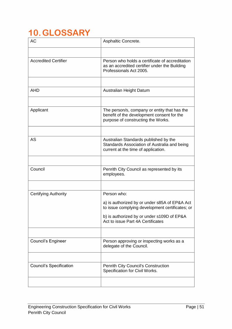
Engineering Construction Specification for Civil Works Page | 51
Penrith City Council
10. GLOSSARY AC Asphaltic Concrete.
Accredited Certifier Person who holds a certificate of accreditation as an accredited certifier under the Building Professionals Act 2005.
AHD Australian Height Datum
Applicant The person/s, company or entity that has the benefit of the development consent for the purpose of constructing the Works.
AS Australian Standards published by the Standards Association of Australia and being current at the time of application.
Council Penrith City Council as represented by its employees.
Certifying Authority Person who:
a) is authorized by or under s85A of EP&A Act to issue complying development certificates; or
b) is authorized by or under s109D of EP&A Act to issue Part 4A Certificates
Council’s Engineer Person approving or inspecting works as a delegate of the Council.
Council’s Specification Penrith City Council's Construction Specification for Civil Works.
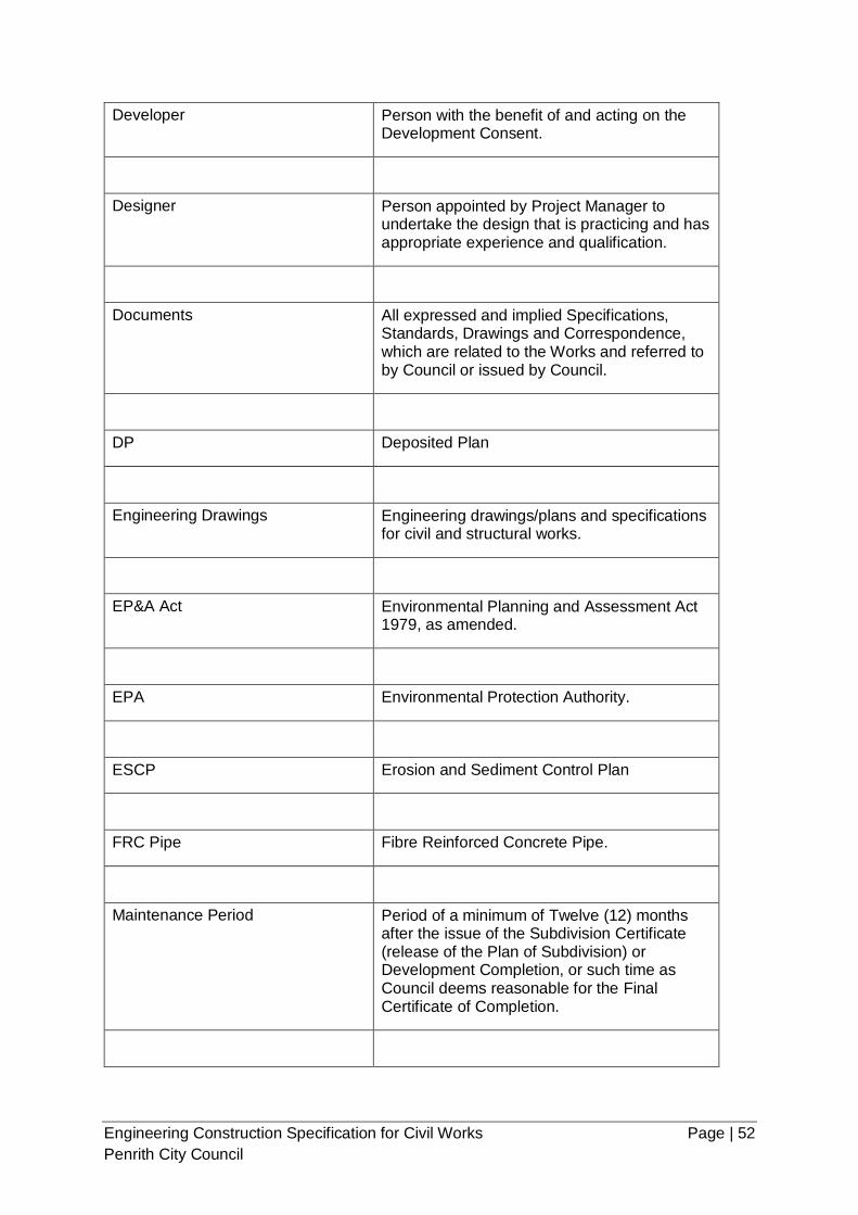
Engineering Construction Specification for Civil Works Page | 52
Penrith City Council
Developer Person with the benefit of and acting on the Development Consent.
Designer Person appointed by Project Manager to undertake the design that is practicing and has appropriate experience and qualification.
Documents All expressed and implied Specifications, Standards, Drawings and Correspondence, which are related to the Works and referred to by Council or issued by Council.
DP Deposited Plan
Engineering Drawings Engineering drawings/plans and specifications for civil and structural works.
EP&A Act Environmental Planning and Assessment Act 1979, as amended.
EPA Environmental Protection Authority.
ESCP Erosion and Sediment Control Plan
FRC Pipe Fibre Reinforced Concrete Pipe.
Maintenance Period Period of a minimum of Twelve (12) months after the issue of the Subdivision Certificate (release of the Plan of Subdivision) or Development Completion, or such time as Council deems reasonable for the Final Certificate of Completion.
Engineering Construction Specification for Civil Works Page | 53
Penrith City Council
NATA National Association of Testing Authorities, Australia.
WHS Work Health & Safety.
PM Permanent Mark
Project Manager Appointed by the developer to manager the development and has sufficient authority and ability to discuss and resolve problems and acts as the principal contact with Council.
Principal Certifying Authority
PCA
The consent authority, the Council, or Accredited Certifier appointed (for building or subdivision work to be carried out on a site) to carry out functions as described in s109E of the EP&A Act.
Principal Contractor The person responsible for the overall co-ordination and control of the carrying out of the works
RCP Reinforced Concrete Pipe.
Registered Engineer Person who is a practising Engineer registered on the Engineers Australia, National Professional Engineers Register (NPER) in the relevant field of work
RL Reduced Level
RMS Roads & Maritime Services, New South Wales.
Engineering Construction Specification for Civil Works Page | 54
Penrith City Council
RRJ Concrete Pipes Rubber ring jointed concrete pipe
Site Area of land being developed under the Subdivision or Development Approval.
SSM State Survey Mark
Superintendent/Supervisor The person appointed by the Project Manager to supervise the construction of the Works on site.
Surveyor Surveyor registered under the Surveying and Spatial Information Act 2002.
SWMP Soil and Water Management Plan
UCS Unconfined Compressive Strength.
UPVC Unplasticised Polyvinyl Chloride (referring to pipe).
VENM Virgin Excavated Natural Material
WAE Works as Executed
Works The development of land as described by the Development Consent and drawings and specifications (the Documents) as proposed by the Applicant and as cited and approved by Council "For Construction" including all the area of the land being developed.
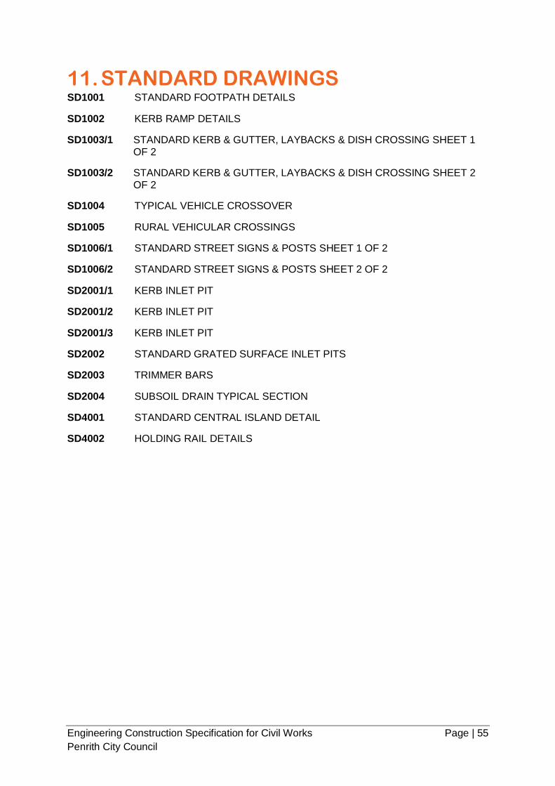
Engineering Construction Specification for Civil Works Page | 55
Penrith City Council
11. STANDARD DRAWINGS SD1001 STANDARD FOOTPATH DETAILS
SD1002 KERB RAMP DETAILS
SD1003/1 STANDARD KERB & GUTTER, LAYBACKS & DISH CROSSING SHEET 1
OF 2
SD1003/2 STANDARD KERB & GUTTER, LAYBACKS & DISH CROSSING SHEET 2
OF 2
SD1004 TYPICAL VEHICLE CROSSOVER
SD1005 RURAL VEHICULAR CROSSINGS
SD1006/1 STANDARD STREET SIGNS & POSTS SHEET 1 OF 2
SD1006/2 STANDARD STREET SIGNS & POSTS SHEET 2 OF 2
SD2001/1 KERB INLET PIT
SD2001/2 KERB INLET PIT
SD2001/3 KERB INLET PIT
SD2002 STANDARD GRATED SURFACE INLET PITS
SD2003 TRIMMER BARS
SD2004 SUBSOIL DRAIN TYPICAL SECTION
SD4001 STANDARD CENTRAL ISLAND DETAIL
SD4002 HOLDING RAIL DETAILS
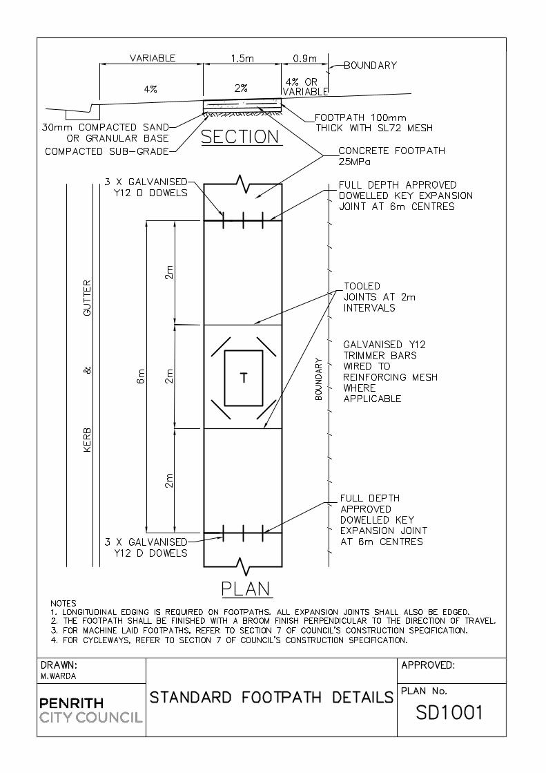


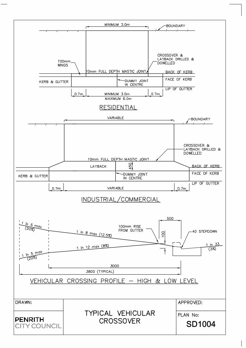
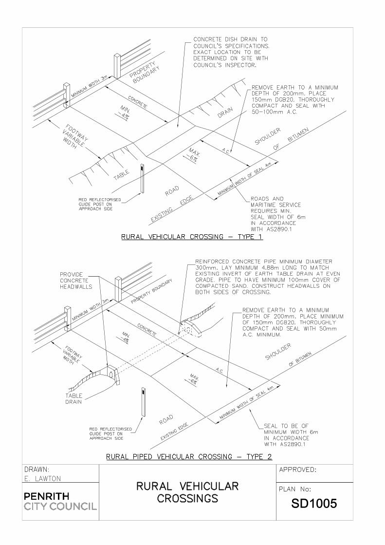

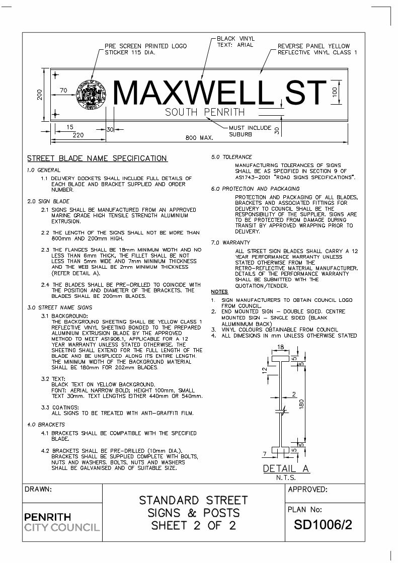


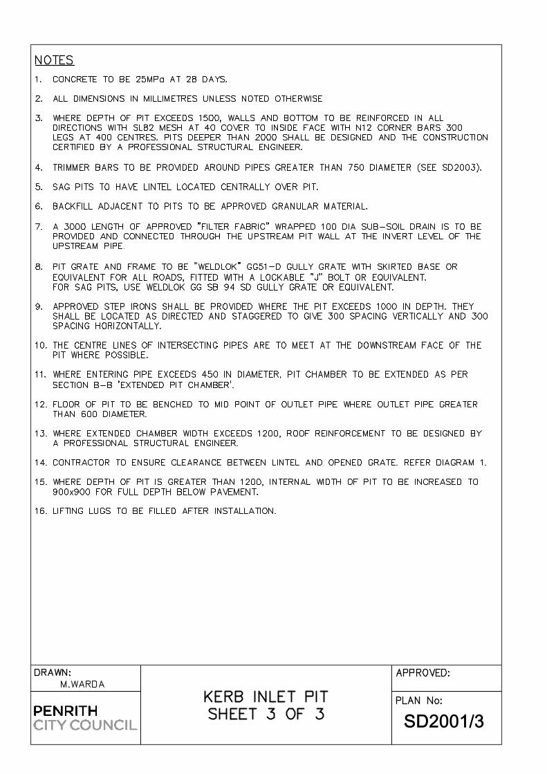
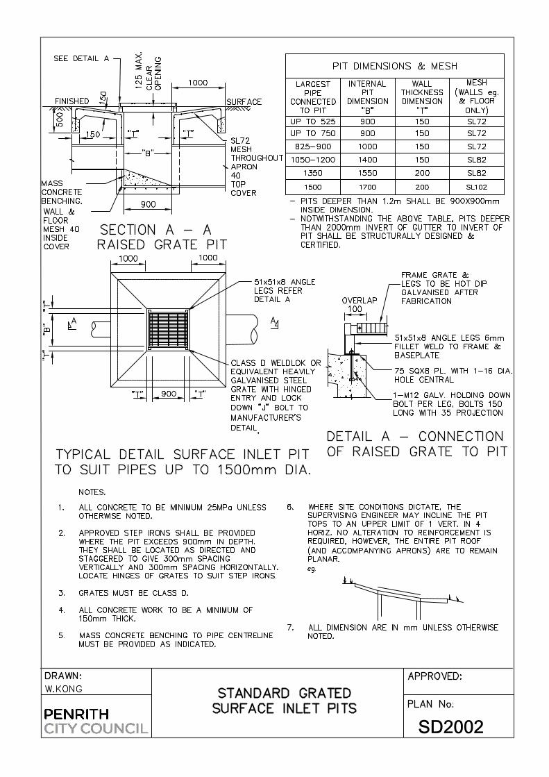


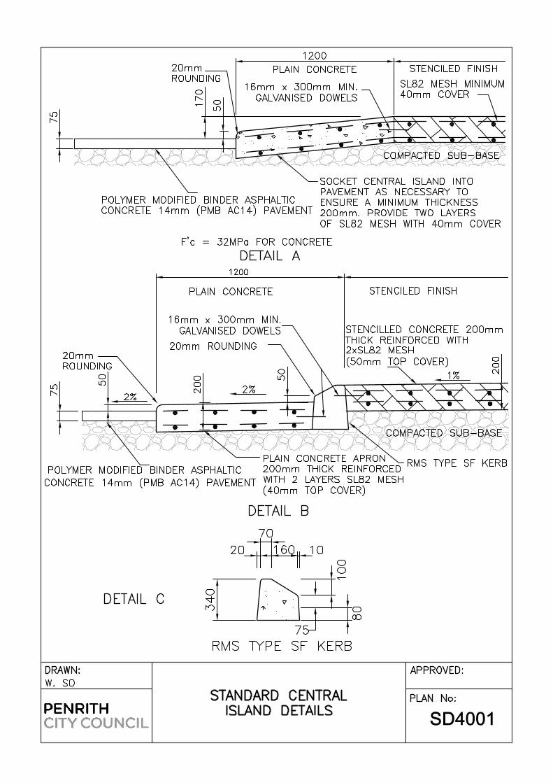
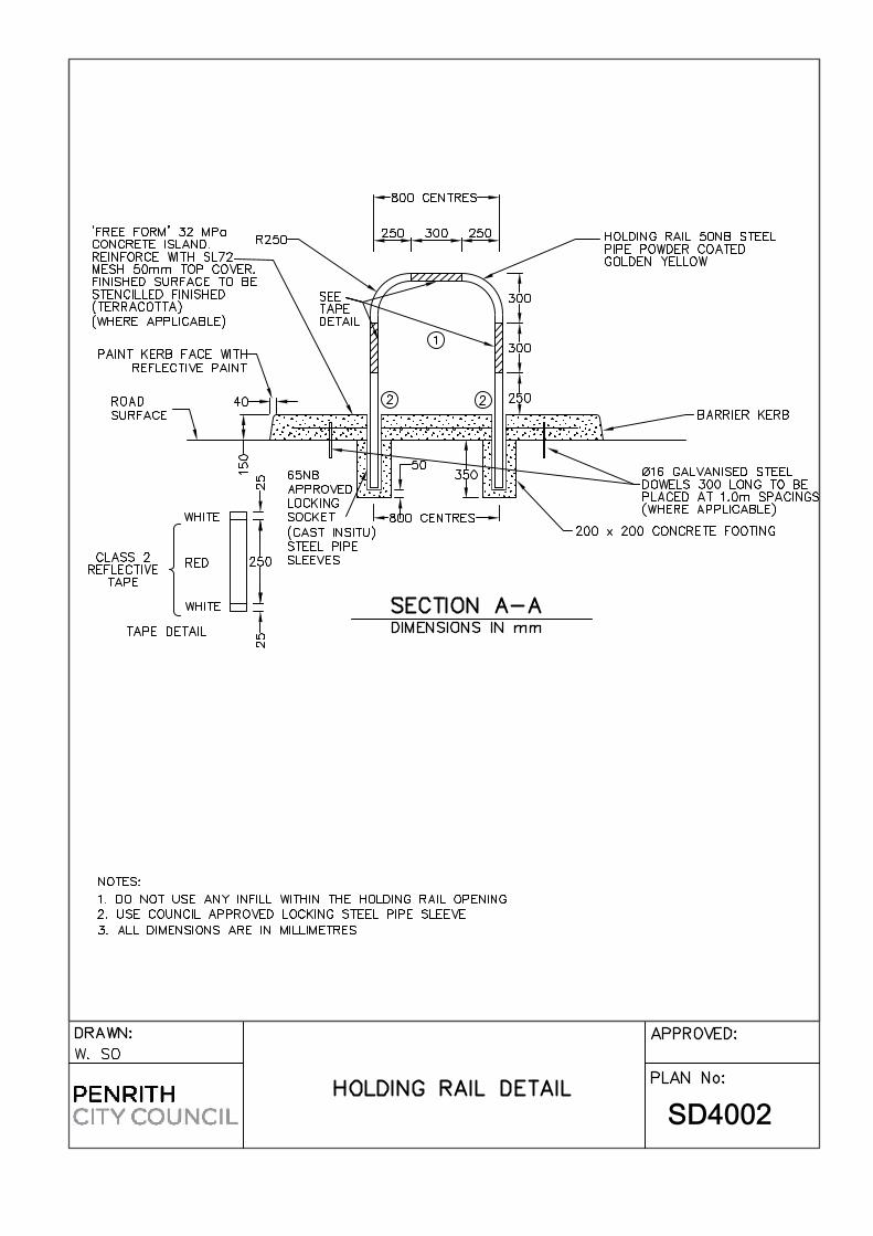

ATTACHMENTS ATTACHMENT 1
CONTRACTORS CHECK LIST

Contractor’s Final Inspection Checklist (To be completed by Contractor)
DA No. CCX No.
Contractor:
Location:
The purpose of this check list is for the contractor to inspect their work prior to booking Council for a final inspection.
It is the contactor’s responsibility to ensure that all works included but not limited to those in this checklist are
completed to Council’s standards.
All WAE plans, CCTV and Road Construction Material Compliance Reports have been submitted to Council for
review prior to the Final Inspection.
Once the checklist has been completed signed and dated by the contractor’s representative it can be submitted
to Council together with a request for Council to conduct the Final Inspection.
The completion of this checklist does not guarantee a satisfactory final inspection.

Y N
1.0 Pavement 1.1 Pavement cleaned, swept and washed where required.
1.2 Gouges or failures repaired with AC. Cold Mix repairs will not be accepted.
1.3 Pavement crack sealed with approved crack sealer.
2.0 Kerb & Gutter 2.1 Kerb and gutter clean swept and washed as required.
2.2 Any bay of kerb & gutter or laybacks (joint to joint) with two cracks or
more have been replaced. (minimum ½ bay replacement)
2.3 Any bay of kerb & gutter with displaced crack or crack equal to or greater than
0.5mm in a bay has been replaced. (Minimum ½ bay replacement).
2.4 Any bay with large chips or gouges (>100mm approx.) has been replaced.
(Minimum ½ bay replacement).
2.5 All silt socks and fabric have been removed from grates and gutter.
2.6 All kerb stormwater outlets clean
Y N 3.0 Stormwater / GPT Pits 3.1 All pits benched (where required) and washed clean
3.2 All step irons installed in pits greater than 1m deep
3.3 All pipes cut flush with the pit walls
3.4 All pits, pipes and lintels rendered.
3.5 All GPT units cleaned
3.6 All CDL pits, stormwater pits and GPT units will be open for final inspection
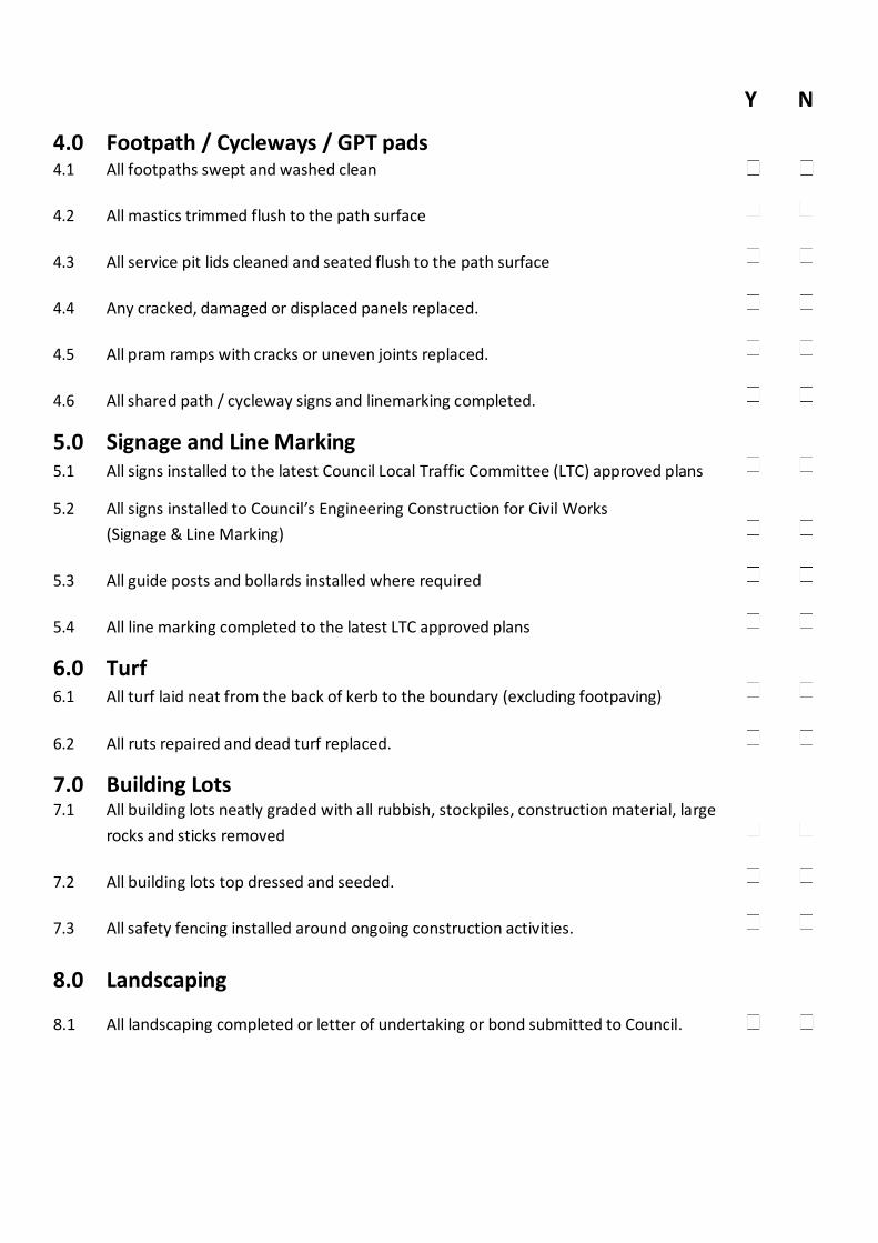
Y N
4.0 Footpath / Cycleways / GPT pads
4.1 All footpaths swept and washed clean
4.2 All mastics trimmed flush to the path surface
4.3 All service pit lids cleaned and seated flush to the path surface
4.4 Any cracked, damaged or displaced panels replaced.
4.5 All pram ramps with cracks or uneven joints replaced.
4.6 All shared path / cycleway signs and linemarking completed.
5.0 Signage and Line Marking 5.1 All signs installed to the latest Council Local Traffic Committee (LTC) approved plans
5.2 All signs installed to Council’s Engineering Construction for Civil Works
(Signage & Line Marking)
5.3 All guide posts and bollards installed where required
5.4 All line marking completed to the latest LTC approved plans
6.0 Turf 6.1 All turf laid neat from the back of kerb to the boundary (excluding footpaving)
6.2 All ruts repaired and dead turf replaced.
7.0 Building Lots 7.1 All building lots neatly graded with all rubbish, stockpiles, construction material, large
rocks and sticks removed
7.2 All building lots top dressed and seeded.
7.3 All safety fencing installed around ongoing construction activities.
8.0 Landscaping 8.1 All landscaping completed or letter of undertaking or bond submitted to Council.

Y N
9.0 Services
9.1 All services installed and functioning.
9.2 Letter of undertaking submitted to Council for all incomplete works.
Additional Comments:
I confirm that all works associated with DA / have been (Name)
completed to the standards of _and Penrith City Council. (Company)
Signature: Position: Date: