Pennsylvania Department of Agriculture Bureau of Ride … Training/Mondial TopScan - Space... ·...
556
Pennsylvania Department of Agriculture Bureau of Ride and Measurement Standards Ride Approval Checklist Name and address of the manufacturer of the Ride or Attraction Mondial PO Box 331 8440 AH Heerenveen Holland Telephone # +31 (0)513 61 01 70 Fax # +31 (0)513 62 24 12 Web site – www.mondial.com Manufacturers name of the Ride – TopScan Pet name of the Ride (if applicable) – Space Roller Minimum/Maximum Height Requirement – Persons under 1.40 m. or 56” may NOT ride. Minimum/Maximum Age Requirement– 12 & older Minimum/Maximum Weight Requirement (not applicable) – Name and address of Pennsylvania Licensed Engineer providing certification Bill Kelley, P.E. (PA License #042731R) Dynamic Designs Inc. 1361 S. Winchester Blvd – 210 San Jose, CA 95128-4328 Telephone # 408-374-7630 Fax # 408-374-1199 E Mail – [email protected] First company to register the ride (if applicable) – Deggeller Attractions (O-493) Danny Abner – 910-279-6018 [email protected] PO Box 238 Stuart, FL 34995 Has the Department received an owner’s manual? – Yes Has the Department received a photograph of the ride or attraction? – Yes Approved name of the ride or attraction – TopScan Notes: Class 1
Transcript of Pennsylvania Department of Agriculture Bureau of Ride … Training/Mondial TopScan - Space... ·...

Pennsylvania Department of Agriculture Bureau of Ride and Measurement Standards
Ride Approval Checklist
Name and address of the manufacturer of the Ride or Attraction Mondial PO Box 331 8440 AH Heerenveen Holland Telephone # +31 (0)513 61 01 70 Fax # +31 (0)513 62 24 12 Web site – www.mondial.com Manufacturers name of the Ride – TopScan Pet name of the Ride (if applicable) – Space Roller Minimum/Maximum Height Requirement – Persons under 1.40 m. or 56” may NOT ride. Minimum/Maximum Age Requirement– 12 & older Minimum/Maximum Weight Requirement (not applicable) – Name and address of Pennsylvania Licensed Engineer providing certification Bill Kelley, P.E. (PA License #042731R) Dynamic Designs Inc. 1361 S. Winchester Blvd – 210 San Jose, CA 95128-4328 Telephone # 408-374-7630 Fax # 408-374-1199 E Mail – [email protected] First company to register the ride (if applicable) – Deggeller Attractions (O-493) Danny Abner – 910-279-6018 [email protected] PO Box 238 Stuart, FL 34995 Has the Department received an owner’s manual? – Yes Has the Department received a photograph of the ride or attraction? – Yes Approved name of the ride or attraction – TopScan Notes: Class 1
CONSTRUCTION AND OPERATING INSTRUCTIONS FOR THE `TOPSCAN'
11 1/4741 I I rilf4117/ o 1141.r/i0 try • v xv tu<
eel` / 8440 AH Hee° ,1vS
a
ad/ 1 / fax 41
CONTENTS
1 CONSTRUCTING THE TOPSCAN
2 CONSTRUCTING THE PLATFORM
3 REAR PANEL
4 ELECTRICAL CONNECTION
5 INSPECTION AFTER CONSTRUCTION AND DAILY INSPECTION
6 OPERATION
7 COMPLETE POWER FAILURE
8 NORMAL OPERATION
9 FAULTS
10 MAINTENANCE AND LUBRICATION
4
6
8
9
10
13
14
15
17

EMERGENCY STOP
Brake I, Release 2. Lock
Arm 2 Speeds
Arm 2 Speeds
Mast
f Mast
(Green) Hydr. unit 1 Turn arm
(Red) Hydr. unit Raisefiower Mast
(Green) Hydr. unit 2 Rel. gondolabrake Turn gondolas
Construction and operating instructions for the Toe.Scan
1 CONSTRUCTING THE TOPSCAN
1.1 Manoeuvre the middle construction trailer into the correct location. Fit the front and rear supports. Connect the auxiliary unit. Raise the middle construction trailer using the four hydraulic cylinders. If necessary the tractor unit (truck) can be uncoupled from the middle construction trailer, Place the wooden prop boards and support plates underneath the ends of the supports and adjust to the correct height (see drawing 115-05-276). Now allow the middle construction trailer to lower onto the support plates.
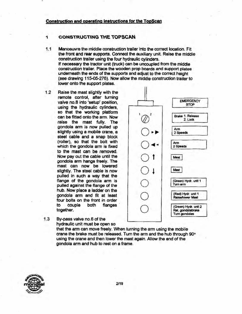
1.2 Raise the mast slightly with the remote control, after turning valve no.8 into 'setup' position, using the hydraulic cylinders, so that the working platform can be fitted onto the arm. Now raise the mast fully. The gondola arm is now pulled up slightly using a mobile crane, a steel cable and a snap block (roller), so that the bolt with which the gondola arm is fixed to the mast can be removed. Now pay out the cable until the gondola arm hangs freely. The mast can now be lowered slightly. The steel cable is now pulled in such a way that the flange of the gondola arm is pulled against the flange of the hub. Now place a ladder on the gondola arm and fit at least four bolts on the front in order to couple both flanges together.
1.3 By-pass valve no.6 of the hydraulic unit must be open so that the arm can move freely. When turning the arm using the mobile crane the brake must be released, Turn the arm and the hub through 90° using the crane and then lower the mast again. Allow the end of the gondola arm and hub to rest on a frame.
1 2/19

• Construction and operatinc instruc tions can
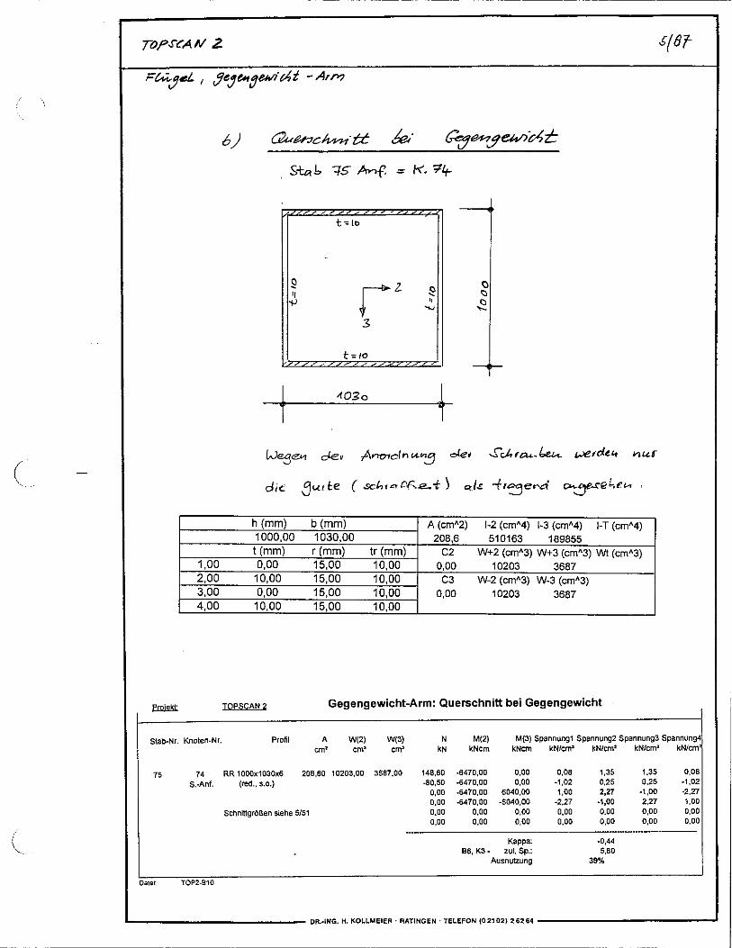
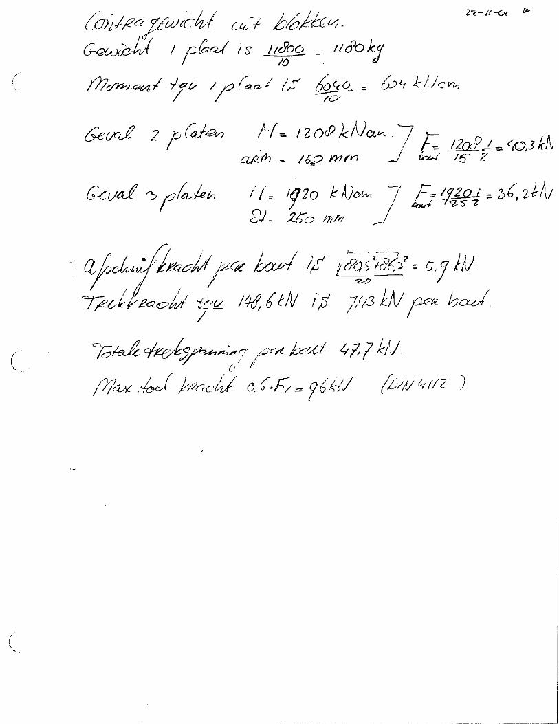
1.4 Fit the counter-arm and raise the mast again, after closing bypass valve n°6. The hydraulic lifting cylinders now need to be locked mechanically. Turn the arm with the hub through 900 so that the counter-arm is at the bottom. Fit a 3.8 T counterweight. Turn arm and hub through 180° and fit two gondolas. The further sequence of assembly is 2.5 T counterweight > 2 gondolas > 3.7 T counterweight > 2 gondolas > 2.5 T counterweight.
1.5 Put valve N08 into 'operation' position.
•

Construction and operating jnstructioni for the TooScan
2 CONSTRUCTING THE PLATFORM
2.1 Place the part of the support, indicated on the drawing by 'Mark 1', which is beside the front-most support legs, on the appropriate stays on the chassis. Lock this part of the support using two 'Mark 1' struts which run towards the chassis.
Suspend support parts Mark 2 and 3 on both sides of support part Mark 1 and prop up with wood in such a way that it is precisely horizontal (for propping up see drawing 115-05-276). Also fit struts Merk 2 as well as Mark 3 and Merk 4 between support part Merk 2/3 and the chassis. Hook in support part Merk 11 and 12 (mirror image) to the frame Mark 2 and 3. Prop these up until they are horizontal,
2.2 Fit support part Merk 4 using strut Mark 5 and adjust to the correct height. The underside of the support part is to be at the same height as the underside of support part Mark 2 or 3. Now fit auxiliary strut Merk 10. Suspend support parts Merk 5 and 6 on both sides of the support part 4 and prop them up such that they are precisely horizontal. Fit the auxiliary supports and hook support part Mark 11/12 into support part Mark 5/6. Hook supports part Mark 13 and 14 at 90° into the frame Mark 516. Prop them up until they are horizontal.
mon al 4/19

Construction and operating instructions for the TopScan
2.3 Fit support part Merk 7b using struts Merk 7 and 8 and auxiliary support Merk 11 and adjust to the correct height. The underside must be horizontal and at the same height as support part Merk 4. Fit both support parts Merk 7a on both sides of support part Merk 7b and prop up until they are horizontal. All of this is adjusted using support Merk 11. Support part Merk 8a and 8b can now be fitted and propped up. Using support Merk 12 the support part is moved into the correct position. Support part Merk 13 (14) are secured to support part Merk 8a (8b), into which support Merk 13 is placed.
2.4 Place gangboards 13, 1 to 6 and 16 on the back row of supports. The platform steps are placed on top of 13 and 16, and on top of them gangboards 14 and 17. Gangboards 18, 12 to 7 and 15 are then fitted.
11 • Supportleg
Supp. 11
Supp. 8a
2.5 Place support legs underneath the platform.
410 2.6 Lay out beams Merk 6-8, fit them together, and fit struts Merk 9 and 10 to support parts Merk 7a or 7b. Prop up the beams so that struts Merk 9 are lying horizontally. Raise frames 1-5 and suspend the end parts Merk 21-29 in between them. The gangboards can now be slid in between them or placed on top of them. These are secured using bolts.
2.7 Suspend the front row of platforms no's. 31-34, 36 to Merk 6-8 and prop up on the front. Now the steps Merk 35 can be fitted. Place the cash desk in the desired position and fit the gates which are to be fixed into position using the appropriate bolts. Fit the spotlight frames.
2.8 Prop up the entire platform in accordance With drawing 115-05-276. All
•pins must be locked using sprung locking pins.
5/19

Merk 5
Merk 9
Merk 2A
Merk 1A
Merk 3A
onstruction and operating instructions for the TooScan
3 REAR PANEL
3.1 Position Merk 4 vertically and fit using pins, work platform Mark 5 can now be swung over. Fit rear panel part 1A (lower) and frames Merk 3A with struts Mark 8 to the platform support. Prop up the frame such that Merk lA is horizontal. Fit struts Mark 9 between the hydro container and
rear wall. Now Merk 2A (upper) must be fitted.
3.2 The support for the work platform Merk 19 can now be secured to the rear panel. Panels 1 R-8R and 11.-81_ can now be hooked in, and on top of these the light riggings 1-9 can be fitted .
6/19

Construction and operating instructions for the TopScan
3.3 Finally, sign 13 can be fitted. Merk 9 and 10 must be inserted into the open square pipes of the support legs. After this strut 11 can be suspended between Merk 9 and 10. The sign Merk 13 can then be hung up using a mobile crane. The sign Merk 13 must be locked to supports Merk 9 and 10 using pins Merk 70. •
•
S
7/19

Construction and ooeratina instructions for the TooScan
4 ELECTRICAL CONNECTION
4.1 The electrical supply is 210 kW. Connection to the public mains may only be carried out by authorised persons.
4.2 After connection the earth switch should first be checked for short circuiting and correct operation.
4.3 Check that the operating position is receiving power.
4A Check the direction of rotation of the machine. The direction of rotation is indicated. If the direction of rotation is incorrect, then the electrician will need to change the wires around.

Construction and operating instructions for the TopScan
5 INSPECTION AFTER CONSTRUCTION AND DAILY INSPECTION
5.1 Inspect all assembly connections to ensure that they are in the correct position and that they are locked to prevent coming loose.
5.2 Inspect the props.
5.3 Inspect the restraints.
The inspection must be carried out daily. A damaged component must be replaced immediately.
a. All check lamps on the gondolas must be intact in order to be able to carry out a proper inspection. Therefore a push-button has been fitted for checking the lamps.
b. All restraints are open - no lamps should be on. If a lamp is on, the restraint or a proximity switch could be broken for example.
c. By operating knobs 3 and 4 on the gondolas followed immediately by knobs 1 and 2, you should be able to hear a click 8 times (teeth).
d. On the first click a check lamp comes on (LED). If the lamp only comes on the second click, then a proximity switch could for example be broken or the tooth may be stuck. On every click the check lamp (LED) stays on. If not, then the lock may be broken or the tooth may be stuck.
e. The restraints are open. When operating knobs 4 and 3 all restraints close. Now turn knob 4 to 'open'. The restraints should now remain hydraulically locked. After three minutes check to see whether a restraint has more than 3 cm of play (has risen). If this is the case then the hydraulic system of these restraints must be bled (see 10.14) using a special hand pump, or a magnetic valve or hydraulic cylinder needs to be replaced. Weekly inspections must be made of the proximity switch to see whether it has a play of 2 mm in relation to the switch plate when the tooth is locked at the lowest point.
5.4 Check the emergency stop switch at low speed.
5.5 Hang up any warning signs which are required.
5.6 Check the main brake. The arm must be in the exit position. When pushing the gondola hub with two persons the arm may not move.
• 9/19

Hydraulic Locking
.f.aw4, ,,,,,,, ,,TIONSONIMIMAINWSOIPOYMANftwAMF.Avvewptor...7.,x,,tomman.v...nlneevor,psrviva,-:7,-rmwo.*,
„
et
. , .
Construction and operating instructions for the TopScan
6 OPERATION
6.1 Both hydraulic units must be switched on. The arm must be in the zero position. The 'zero position arm' and 'brake system release' lamps on the operating panel must be on. If the mast is in the lowest position, the 'mast down' lamp comes on and the gondolas can be boarded.
6.2 The restraints are closed using the knobs which are located on the end of the gondola. The attendance should see to it that all the restraints are all the way to the clients body. The operating sequence is as follows: 4 > 3 > 2 > 1. Readiness is indicated by the lamps.
6.3 If this is not the case, then inspection of the lamps will indicate which restraint is not closed properly. By either manually correcting or by repeating the opening and closing sequence the problem should pass If all of the inspection lamps are on, then all of the ready lamp should also be on.
10/19

The back solid against chair back
•
I
Construction and o eratin • instructions for the To • Scan
After he has closed and locked the restrainbars, the employee of the gondolas is obliged to check if the restrainbar is up to the body. It is prohibited to take bags, loose clothing or other objects into the gondola and to put them in between the body and the restrainbar.
The employee of the gondolas has to check:
1. The back solid against chair back 2. To both sides of the horn a leg 3. No loose objects in between body and restrainbar 4. Hold grip
6.4 All gondolas must be closed in this way. Once all 12 ready lamps are on then the ready lamp will also be on at the operating panel in the cash desk. The 'restraint locks open' lamp goes out, The 'restraints locked' lamp comes on.
6,5 Press the button 'start raising mast' - the mast will rise up. Once the mast has reached its highest position, the 'mast up' lamp will come on. The 'mast locked' lamp should automatically come on. Now the 'brake system release' button can be operated. The brake button does not need to operated if it is set to 'brake system release' and semi-automatic operation is being used. The arm as well as the gondolas can now be rotated by turning the 'arm joystick arm' or the 'gondola joystick' to the left or right. The gondolas do not have a zero position.
11119

WSNUT.1•11•711111WW1011.1.1010.,MPO....1101.16.4.1VA.r.V....M.,...A.0.1.5
Construction and operatinq instructions for the TopScan
6.6 Ending of the ride.
Both joysticks must be turned to 0. The arm must be brought to the zero position using the joystick. The brake can be operated when the 'arm zero position' lamp is on. Operation of the brake is not necessary during semi-automatic operation.
By pressing the 'start lowering mast' button, the mast moves to its lowered position. The 'mast down' lamp should come on. The restraints are opened, after the mast is in its lowest position, by pressing the buttons on the gondolas in the following sequence: 1 > 2 > 3 > 4. The movement of the mast can be stopped using the 'stop mast rising/lowering' button.
6.7 The 'emergency stop' button may only be used in situations where real danger exists. The function of this button can be tested at low speed operation.
12/19

Construction and operating instructions for the TopScan
7 COMPLETE POWER FAILURE
7.1 In the case of power failure or drive failure it must be ensured that the passengers are able to leave the gondolas without any danger to them. To this end the following procedures are to be carried out:
7.2 Situation in the case of more than 15 persons seated in the gondolas:
a Turn off main switch. b By-pass valve no.6 beside the main unit must be opened. Valve 7
must be closed. c Pump the brake on the main drive free using the hydraulic hand
pump. d The gondolas will automatically turn down. When they are down
the brake must be applied again. e To lower the mast the by-pass valve of the hydraulic cylinders
must be opened. Therefore valve 9 must be closed and a hydraulic hand pump connected to the matching test nipple. By generating a pressure of at least 30 Bar the mast will lower slowly.
f The restraints can be opened using batteries. The cable connection on the batteries and the connection to the gondola is present. The rest of the operation is the same as during normal operation. (There is still sufficient air in the tank).
g The batteries must be inspected weekly.
7.3 In the case of there being less than 15 persons seated in the gondolas:
a Turn off main switch. b By-pass valve no. 6 beside the main unit must be opened. Valve
7 must be closed. c The steel cable (which is already fitted between mast head and
counter weight) must be lowered at the counterweight. The steel cable must now be fitted to tackle.
d This tackle is fitted to the platform depending on where the gondolas are located. The steel cable must now be pulled tight (See image on page 15).
e The brake of the main drive must now be pumped free using the hand pump.
f The gondolas can now be pulled down using the tackle. g Before the cable is changed from position no. 1 to position no. 2
for example, the brake must first be applied. Now continue from point e) until the gondolas are just above the platform.
h Once the gondolas are in the middle above the platform the brake must be applied again. Be sure that the gondolas are in null position. As described from point 7.2 (e).
13/19 sal

Arm turning speed Arm acceleration time Braking time Arm over-pressure valve Gondola cross turning speed Gondola cross acceleration Gondola cross braking time Gondola cross over-pressure valve
8.3 t/min. 8 sec. 8 sec. 220 bar 10 t/min 6 sec. 6 sec. 190 bar
rj
r.4
en,
Construction and operating instructions for the TopScan
8 NORMAL OPERATION
8.1 The maximum turning speeds, acceleration time, braking time, over- pressure valves setting and mechanical pump limiting set during the final inspection may not be changed. The machine has been set up with the following values:
8.2 During operation the operating position must be constantly manned by a trained person of at least 18 years of age.
8.3 During the ride no member of the public or operating personnel may be in the danger zone.
8.4 A member of staff must stand beside the boarding and exit platform.
a.s When the passengers take their seats, a member of staff has to check that they have their back solid to the chairback and on both sides of the
horn a leg. Furthermore he is obliged to check that, after he has closed and locked the restrainbars, the restrainbar is up to the body. It is prohibited to take bags, loose clothing or other objects into the gondola and to put them in between the body and the restrainbar.
8.6 Operating personnel must continually monitor the machine.
8.7 Passengers should be spread between gondolas as evenly as possible.
8.8 Children under the age of 12 and persons under 1.40 m. may not board the ride.
8.9 Persons intoxicated with alcohol may not board the ride.
8.10 Loose articles (such as hats, scarves, glasses, etc.) must be handed in to a member of staff before boarding the ride.
8.11 Instructions 8, 9 and 10 must be illustrated clearly using signs.
•
14/19
Construction and operating instructions for the TopScan
9 FAULTS
9.1 A number of fault lamps are located on every switch box: control pressure too low oil temperature too high
- oil level too low - power fault
direction of rotation check cooling motor fault
If one of these lamps is on then the fault must be resolved first before the machine may be started again. If a fault can not be resolved then the supplier must be consulted.
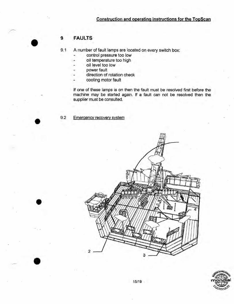
9.2 Emergency recovery system
•

Construction and operating instructions for the TopScan
The possibility of bringing the arm above the platform in the event of a
fault: a See point 7.2. b Mechanically.
Using the Tirford tackle to pull the arm down (see description c Hydraulically.
1. Close valve no. 1 + 2 2. Open valve no. 3 + 4 3 Open valve no. 5 . Switch on auxiliary hydraulic unit, open the valve on the outside
of the container and the arm will begin to move. 5. Check oil level in the oil tank after using this pomp. If the level
is too low, then open valve no. 0 and fill the oil tank. 6. After all passengers have alighted, turn all valves back to their
original positions.
16/19

1"711 ---- i L." lbgillrriohi linfliritil iiii)̀ j:1117-11111 1iii
Construction and operating instructions for the TopScan
10 MAINTENANCE AND LUBRICATION
10.1 All bolt connections must be inspected for tension after every 50 operating hours or at least every week.
10.2 Main rotary ring, gondola cross rotary ring and gondola rotary rings must be lubricated every 50 hours or 1 x week. They are lubricated with ESSO Beacon 2 prior to delivery.
10.3 Gearbox of the arm drive. Capacity approximately 36 litres of SHELL Omala EP150. Check the oil level approximately every 200 operating hours.
10.4 Gearbox of the gondola drive. Capacity approximately 8 litres of SHELL Omala EP150. Check the oil level approximately every 200 operating hours.
10.5 Changing the oil in the gearbox of the arm drive
The first oil change must be carried out after 200 operating hours, and then after 400 operating hours, though at least 3 times a year.
Instructions for changing the oil in the gearbox of the arm drive.
1. Move the safetyfences 8 at the back and fences 2 at the right of the main platform.
2. Turn the gondola-arm and contraweight-arm to horizontal position.
3. Lower the mast until the centre-shaft of the gearbox is in horizontal position.
4. Rotate now the gondola-arm and contraweight-arm counterclockwise/ I est*.
17/19

10.10 All parts of the passenger locking system (restraint locking, pneumatic and hydraulic) and the frames of the seats must be inspected at least once per week for correct operation. The polyester covers on the backs
- of the seats will have to be removed for this. Hydraulic locking: if the
18/19 /*as mkt\
1011
Construction and operating instructions for the TopScan
until the contraweights almost touch the platform at the right.
5. The oil changepoints are know in right position. To accelerate the oilchange, open the uppermost changepoint after the undermost_
1111111111111111V111111111111111 I I = I 1 lll 111 i 111
1111 1 111111111111111111111111 1111111111111111111111111 1111111111111111111111111111111111111111111111 Jo .110
111611411rit
10.6 Hydraulic unit of the main drive.
Capacity approximately 600 litres of SHELL Tellus T46. Also see instructions from Mannesmann Rexroth.
10.7 Hydraulic unit of gondola drive.
Capacity approximately 100 litres of SHELL Tellus T46. Also see instructions from Mannesmann Rexroth.
10.8 Main lubricating point on the mast: to be inspected 1 x year by the manufacturer.
10.9 Air installation
Pneumatic. The compressor is oil free. The water in the tank must be drained weekly.
rk

Connection
Construction and operating instructions for the TopScan
•
•
restraints do not close quickly enough, the hydraulic cylinders must be topped up with oi( (SHELL Tel lus 22T). The pre-tension (when the restraints are closed) is at least 8 bar. The maximum pre-tension is 10 bar. Note: check for air in the hydraulic system, if present, then vent. See 10.14.
10.11 The battery of the PLC must be changed every year (if present).
10.12 The most important parts of the ride (gondolas, arm and mast) must be checked regularly for crack formation.
10.13 Inspection of the hydraulic locking system. See 5.3 (e).
10.14 Venting of the hydraulic locking system. Restraints must all be open. Knob 3 to "open". Check oil level in the hand pump (SHELL Tellus 22T).
Connect the hand pump as described below: the valve on the pump must be closed; connect the transparent hose to the top connection; connect the black hose to the bottom connection; pump slowly using the hand pump until all the "air" is out of the system. Fit the transparent hose; open and close the restraints a few times. Fit the transparent hose once again and resume pumping with the hand pump until all of the air has been removed; remove the transparent hose; with the restraints open, slowly pump to approximately 16 bar (with accumulator of 4 bar); continue inspection of the hydraulic locking system. See 5.3 (e).
if the restraint closes too slowly - then the pressure is too low therefore increase the pressure
=> if the restraint closes too quickly - then the pressure is too high therefore reduce the pressure
=>
if the restraint closes the same as all the other restraints - then the everything is in order
=> if the restraint does not close at all - the accumulator is broken or empty.
S
19/19


CONSTRUCTION AND OPERATING INSTRUCTIONS FOR THE `TOPSCAN'
11 1/4741 I I rilf4117/ o 1141.r/i0 try • v xv tu<
eel` / 8440 AH Hee° ,1vS
a
ad/ 1 / fax 41
CONTENTS
1 CONSTRUCTING THE TOPSCAN
2 CONSTRUCTING THE PLATFORM
3 REAR PANEL
4 ELECTRICAL CONNECTION
5 INSPECTION AFTER CONSTRUCTION AND DAILY INSPECTION
6 OPERATION
7 COMPLETE POWER FAILURE
8 NORMAL OPERATION
9 FAULTS
10 MAINTENANCE AND LUBRICATION
4
6
8
9
10
13
14
15
17
EMERGENCY STOP
Brake I, Release 2. Lock
Arm 2 Speeds
Arm 2 Speeds
Mast
f Mast
(Green) Hydr. unit 1 Turn arm
(Red) Hydr. unit Raisefiower Mast
(Green) Hydr. unit 2 Rel. gondolabrake Turn gondolas
Construction and operating instructions for the Toe.Scan
1 CONSTRUCTING THE TOPSCAN
1.1 Manoeuvre the middle construction trailer into the correct location. Fit the front and rear supports. Connect the auxiliary unit. Raise the middle construction trailer using the four hydraulic cylinders. If necessary the tractor unit (truck) can be uncoupled from the middle construction trailer, Place the wooden prop boards and support plates underneath the ends of the supports and adjust to the correct height (see drawing 115-05-276). Now allow the middle construction trailer to lower onto the support plates.
1.2 Raise the mast slightly with the remote control, after turning valve no.8 into 'setup' position, using the hydraulic cylinders, so that the working platform can be fitted onto the arm. Now raise the mast fully. The gondola arm is now pulled up slightly using a mobile crane, a steel cable and a snap block (roller), so that the bolt with which the gondola arm is fixed to the mast can be removed. Now pay out the cable until the gondola arm hangs freely. The mast can now be lowered slightly. The steel cable is now pulled in such a way that the flange of the gondola arm is pulled against the flange of the hub. Now place a ladder on the gondola arm and fit at least four bolts on the front in order to couple both flanges together.
1.3 By-pass valve no.6 of the hydraulic unit must be open so that the arm can move freely. When turning the arm using the mobile crane the brake must be released, Turn the arm and the hub through 90° using the crane and then lower the mast again. Allow the end of the gondola arm and hub to rest on a frame.
1 2/19

• Construction and operatinc instruc tions can
1.4 Fit the counter-arm and raise the mast again, after closing bypass valve n°6. The hydraulic lifting cylinders now need to be locked mechanically. Turn the arm with the hub through 900 so that the counter-arm is at the bottom. Fit a 3.8 T counterweight. Turn arm and hub through 180° and fit two gondolas. The further sequence of assembly is 2.5 T counterweight > 2 gondolas > 3.7 T counterweight > 2 gondolas > 2.5 T counterweight.
1.5 Put valve N08 into 'operation' position.
•

Construction and operating jnstructioni for the TooScan
2 CONSTRUCTING THE PLATFORM
2.1 Place the part of the support, indicated on the drawing by 'Mark 1', which is beside the front-most support legs, on the appropriate stays on the chassis. Lock this part of the support using two 'Mark 1' struts which run towards the chassis.
Suspend support parts Mark 2 and 3 on both sides of support part Mark 1 and prop up with wood in such a way that it is precisely horizontal (for propping up see drawing 115-05-276). Also fit struts Merk 2 as well as Mark 3 and Merk 4 between support part Merk 2/3 and the chassis. Hook in support part Merk 11 and 12 (mirror image) to the frame Mark 2 and 3. Prop these up until they are horizontal,
2.2 Fit support part Merk 4 using strut Mark 5 and adjust to the correct height. The underside of the support part is to be at the same height as the underside of support part Mark 2 or 3. Now fit auxiliary strut Merk 10. Suspend support parts Merk 5 and 6 on both sides of the support part 4 and prop them up such that they are precisely horizontal. Fit the auxiliary supports and hook support part Mark 11/12 into support part Mark 5/6. Hook supports part Mark 13 and 14 at 90° into the frame Mark 516. Prop them up until they are horizontal.
mon al 4/19

Construction and operating instructions for the TopScan
2.3 Fit support part Merk 7b using struts Merk 7 and 8 and auxiliary support Merk 11 and adjust to the correct height. The underside must be horizontal and at the same height as support part Merk 4. Fit both support parts Merk 7a on both sides of support part Merk 7b and prop up until they are horizontal. All of this is adjusted using support Merk 11. Support part Merk 8a and 8b can now be fitted and propped up. Using support Merk 12 the support part is moved into the correct position. Support part Merk 13 (14) are secured to support part Merk 8a (8b), into which support Merk 13 is placed.
2.4 Place gangboards 13, 1 to 6 and 16 on the back row of supports. The platform steps are placed on top of 13 and 16, and on top of them gangboards 14 and 17. Gangboards 18, 12 to 7 and 15 are then fitted.
11 • Supportleg
Supp. 11
Supp. 8a
2.5 Place support legs underneath the platform.
410 2.6 Lay out beams Merk 6-8, fit them together, and fit struts Merk 9 and 10 to support parts Merk 7a or 7b. Prop up the beams so that struts Merk 9 are lying horizontally. Raise frames 1-5 and suspend the end parts Merk 21-29 in between them. The gangboards can now be slid in between them or placed on top of them. These are secured using bolts.
2.7 Suspend the front row of platforms no's. 31-34, 36 to Merk 6-8 and prop up on the front. Now the steps Merk 35 can be fitted. Place the cash desk in the desired position and fit the gates which are to be fixed into position using the appropriate bolts. Fit the spotlight frames.
2.8 Prop up the entire platform in accordance With drawing 115-05-276. All
•pins must be locked using sprung locking pins.
5/19

Merk 5
Merk 9
Merk 2A
Merk 1A
Merk 3A
onstruction and operating instructions for the TooScan
3 REAR PANEL
3.1 Position Merk 4 vertically and fit using pins, work platform Mark 5 can now be swung over. Fit rear panel part 1A (lower) and frames Merk 3A with struts Mark 8 to the platform support. Prop up the frame such that Merk lA is horizontal. Fit struts Mark 9 between the hydro container and
rear wall. Now Merk 2A (upper) must be fitted.
3.2 The support for the work platform Merk 19 can now be secured to the rear panel. Panels 1 R-8R and 11.-81_ can now be hooked in, and on top of these the light riggings 1-9 can be fitted .
6/19

Construction and operating instructions for the TopScan
3.3 Finally, sign 13 can be fitted. Merk 9 and 10 must be inserted into the open square pipes of the support legs. After this strut 11 can be suspended between Merk 9 and 10. The sign Merk 13 can then be hung up using a mobile crane. The sign Merk 13 must be locked to supports Merk 9 and 10 using pins Merk 70. •
•
S
7/19

Construction and ooeratina instructions for the TooScan
4 ELECTRICAL CONNECTION
4.1 The electrical supply is 210 kW. Connection to the public mains may only be carried out by authorised persons.
4.2 After connection the earth switch should first be checked for short circuiting and correct operation.
4.3 Check that the operating position is receiving power.
4A Check the direction of rotation of the machine. The direction of rotation is indicated. If the direction of rotation is incorrect, then the electrician will need to change the wires around.

Construction and operating instructions for the TopScan
5 INSPECTION AFTER CONSTRUCTION AND DAILY INSPECTION
5.1 Inspect all assembly connections to ensure that they are in the correct position and that they are locked to prevent coming loose.
5.2 Inspect the props.
5.3 Inspect the restraints.
The inspection must be carried out daily. A damaged component must be replaced immediately.
a. All check lamps on the gondolas must be intact in order to be able to carry out a proper inspection. Therefore a push-button has been fitted for checking the lamps.
b. All restraints are open - no lamps should be on. If a lamp is on, the restraint or a proximity switch could be broken for example.
c. By operating knobs 3 and 4 on the gondolas followed immediately by knobs 1 and 2, you should be able to hear a click 8 times (teeth).
d. On the first click a check lamp comes on (LED). If the lamp only comes on the second click, then a proximity switch could for example be broken or the tooth may be stuck. On every click the check lamp (LED) stays on. If not, then the lock may be broken or the tooth may be stuck.
e. The restraints are open. When operating knobs 4 and 3 all restraints close. Now turn knob 4 to 'open'. The restraints should now remain hydraulically locked. After three minutes check to see whether a restraint has more than 3 cm of play (has risen). If this is the case then the hydraulic system of these restraints must be bled (see 10.14) using a special hand pump, or a magnetic valve or hydraulic cylinder needs to be replaced. Weekly inspections must be made of the proximity switch to see whether it has a play of 2 mm in relation to the switch plate when the tooth is locked at the lowest point.
5.4 Check the emergency stop switch at low speed.
5.5 Hang up any warning signs which are required.
5.6 Check the main brake. The arm must be in the exit position. When pushing the gondola hub with two persons the arm may not move.
• 9/19

Hydraulic Locking
.f.aw4, ,,,,,,, ,,TIONSONIMIMAINWSOIPOYMANftwAMF.Avvewptor...7.,x,,tomman.v...nlneevor,psrviva,-:7,-rmwo.*,
„
et
. , .
Construction and operating instructions for the TopScan
6 OPERATION
6.1 Both hydraulic units must be switched on. The arm must be in the zero position. The 'zero position arm' and 'brake system release' lamps on the operating panel must be on. If the mast is in the lowest position, the 'mast down' lamp comes on and the gondolas can be boarded.
6.2 The restraints are closed using the knobs which are located on the end of the gondola. The attendance should see to it that all the restraints are all the way to the clients body. The operating sequence is as follows: 4 > 3 > 2 > 1. Readiness is indicated by the lamps.
6.3 If this is not the case, then inspection of the lamps will indicate which restraint is not closed properly. By either manually correcting or by repeating the opening and closing sequence the problem should pass If all of the inspection lamps are on, then all of the ready lamp should also be on.
10/19

The back solid against chair back
•
I
Construction and o eratin • instructions for the To • Scan
After he has closed and locked the restrainbars, the employee of the gondolas is obliged to check if the restrainbar is up to the body. It is prohibited to take bags, loose clothing or other objects into the gondola and to put them in between the body and the restrainbar.
The employee of the gondolas has to check:
1. The back solid against chair back 2. To both sides of the horn a leg 3. No loose objects in between body and restrainbar 4. Hold grip
6.4 All gondolas must be closed in this way. Once all 12 ready lamps are on then the ready lamp will also be on at the operating panel in the cash desk. The 'restraint locks open' lamp goes out, The 'restraints locked' lamp comes on.
6,5 Press the button 'start raising mast' - the mast will rise up. Once the mast has reached its highest position, the 'mast up' lamp will come on. The 'mast locked' lamp should automatically come on. Now the 'brake system release' button can be operated. The brake button does not need to operated if it is set to 'brake system release' and semi-automatic operation is being used. The arm as well as the gondolas can now be rotated by turning the 'arm joystick arm' or the 'gondola joystick' to the left or right. The gondolas do not have a zero position.
11119

WSNUT.1•11•711111WW1011.1.1010.,MPO....1101.16.4.1VA.r.V....M.,...A.0.1.5
Construction and operatinq instructions for the TopScan
6.6 Ending of the ride.
Both joysticks must be turned to 0. The arm must be brought to the zero position using the joystick. The brake can be operated when the 'arm zero position' lamp is on. Operation of the brake is not necessary during semi-automatic operation.
By pressing the 'start lowering mast' button, the mast moves to its lowered position. The 'mast down' lamp should come on. The restraints are opened, after the mast is in its lowest position, by pressing the buttons on the gondolas in the following sequence: 1 > 2 > 3 > 4. The movement of the mast can be stopped using the 'stop mast rising/lowering' button.
6.7 The 'emergency stop' button may only be used in situations where real danger exists. The function of this button can be tested at low speed operation.
12/19

Construction and operating instructions for the TopScan
7 COMPLETE POWER FAILURE
7.1 In the case of power failure or drive failure it must be ensured that the passengers are able to leave the gondolas without any danger to them. To this end the following procedures are to be carried out:
7.2 Situation in the case of more than 15 persons seated in the gondolas:
a Turn off main switch. b By-pass valve no.6 beside the main unit must be opened. Valve 7
must be closed. c Pump the brake on the main drive free using the hydraulic hand
pump. d The gondolas will automatically turn down. When they are down
the brake must be applied again. e To lower the mast the by-pass valve of the hydraulic cylinders
must be opened. Therefore valve 9 must be closed and a hydraulic hand pump connected to the matching test nipple. By generating a pressure of at least 30 Bar the mast will lower slowly.
f The restraints can be opened using batteries. The cable connection on the batteries and the connection to the gondola is present. The rest of the operation is the same as during normal operation. (There is still sufficient air in the tank).
g The batteries must be inspected weekly.
7.3 In the case of there being less than 15 persons seated in the gondolas:
a Turn off main switch. b By-pass valve no. 6 beside the main unit must be opened. Valve
7 must be closed. c The steel cable (which is already fitted between mast head and
counter weight) must be lowered at the counterweight. The steel cable must now be fitted to tackle.
d This tackle is fitted to the platform depending on where the gondolas are located. The steel cable must now be pulled tight (See image on page 15).
e The brake of the main drive must now be pumped free using the hand pump.
f The gondolas can now be pulled down using the tackle. g Before the cable is changed from position no. 1 to position no. 2
for example, the brake must first be applied. Now continue from point e) until the gondolas are just above the platform.
h Once the gondolas are in the middle above the platform the brake must be applied again. Be sure that the gondolas are in null position. As described from point 7.2 (e).
13/19 sal

Arm turning speed Arm acceleration time Braking time Arm over-pressure valve Gondola cross turning speed Gondola cross acceleration Gondola cross braking time Gondola cross over-pressure valve
8.3 t/min. 8 sec. 8 sec. 220 bar 10 t/min 6 sec. 6 sec. 190 bar
rj
r.4
en,
Construction and operating instructions for the TopScan
8 NORMAL OPERATION
8.1 The maximum turning speeds, acceleration time, braking time, over- pressure valves setting and mechanical pump limiting set during the final inspection may not be changed. The machine has been set up with the following values:
8.2 During operation the operating position must be constantly manned by a trained person of at least 18 years of age.
8.3 During the ride no member of the public or operating personnel may be in the danger zone.
8.4 A member of staff must stand beside the boarding and exit platform.
a.s When the passengers take their seats, a member of staff has to check that they have their back solid to the chairback and on both sides of the
horn a leg. Furthermore he is obliged to check that, after he has closed and locked the restrainbars, the restrainbar is up to the body. It is prohibited to take bags, loose clothing or other objects into the gondola and to put them in between the body and the restrainbar.
8.6 Operating personnel must continually monitor the machine.
8.7 Passengers should be spread between gondolas as evenly as possible.
8.8 Children under the age of 12 and persons under 1.40 m. may not board the ride.
8.9 Persons intoxicated with alcohol may not board the ride.
8.10 Loose articles (such as hats, scarves, glasses, etc.) must be handed in to a member of staff before boarding the ride.
8.11 Instructions 8, 9 and 10 must be illustrated clearly using signs.
•
14/19

Construction and operating instructions for the TopScan
9 FAULTS
9.1 A number of fault lamps are located on every switch box: control pressure too low oil temperature too high
- oil level too low - power fault
direction of rotation check cooling motor fault
If one of these lamps is on then the fault must be resolved first before the machine may be started again. If a fault can not be resolved then the supplier must be consulted.
9.2 Emergency recovery system
•

Construction and operating instructions for the TopScan
The possibility of bringing the arm above the platform in the event of a
fault: a See point 7.2. b Mechanically.
Using the Tirford tackle to pull the arm down (see description c Hydraulically.
1. Close valve no. 1 + 2 2. Open valve no. 3 + 4 3 Open valve no. 5 . Switch on auxiliary hydraulic unit, open the valve on the outside
of the container and the arm will begin to move. 5. Check oil level in the oil tank after using this pomp. If the level
is too low, then open valve no. 0 and fill the oil tank. 6. After all passengers have alighted, turn all valves back to their
original positions.
16/19

1"711 ---- i L." lbgillrriohi linfliritil iiii)̀ j:1117-11111 1iii
Construction and operating instructions for the TopScan
10 MAINTENANCE AND LUBRICATION
10.1 All bolt connections must be inspected for tension after every 50 operating hours or at least every week.
10.2 Main rotary ring, gondola cross rotary ring and gondola rotary rings must be lubricated every 50 hours or 1 x week. They are lubricated with ESSO Beacon 2 prior to delivery.
10.3 Gearbox of the arm drive. Capacity approximately 36 litres of SHELL Omala EP150. Check the oil level approximately every 200 operating hours.
10.4 Gearbox of the gondola drive. Capacity approximately 8 litres of SHELL Omala EP150. Check the oil level approximately every 200 operating hours.
10.5 Changing the oil in the gearbox of the arm drive
The first oil change must be carried out after 200 operating hours, and then after 400 operating hours, though at least 3 times a year.
Instructions for changing the oil in the gearbox of the arm drive.
1. Move the safetyfences 8 at the back and fences 2 at the right of the main platform.
2. Turn the gondola-arm and contraweight-arm to horizontal position.
3. Lower the mast until the centre-shaft of the gearbox is in horizontal position.
4. Rotate now the gondola-arm and contraweight-arm counterclockwise/ I est*.
17/19

10.10 All parts of the passenger locking system (restraint locking, pneumatic and hydraulic) and the frames of the seats must be inspected at least once per week for correct operation. The polyester covers on the backs
- of the seats will have to be removed for this. Hydraulic locking: if the
18/19 /*as mkt\
1011
Construction and operating instructions for the TopScan
until the contraweights almost touch the platform at the right.
5. The oil changepoints are know in right position. To accelerate the oilchange, open the uppermost changepoint after the undermost_
1111111111111111V111111111111111 I I = I 1 lll 111 i 111
1111 1 111111111111111111111111 1111111111111111111111111 1111111111111111111111111111111111111111111111 Jo .110
111611411rit
10.6 Hydraulic unit of the main drive.
Capacity approximately 600 litres of SHELL Tellus T46. Also see instructions from Mannesmann Rexroth.
10.7 Hydraulic unit of gondola drive.
Capacity approximately 100 litres of SHELL Tellus T46. Also see instructions from Mannesmann Rexroth.
10.8 Main lubricating point on the mast: to be inspected 1 x year by the manufacturer.
10.9 Air installation
Pneumatic. The compressor is oil free. The water in the tank must be drained weekly.
rk

Connection
Construction and operating instructions for the TopScan
•
•
restraints do not close quickly enough, the hydraulic cylinders must be topped up with oi( (SHELL Tel lus 22T). The pre-tension (when the restraints are closed) is at least 8 bar. The maximum pre-tension is 10 bar. Note: check for air in the hydraulic system, if present, then vent. See 10.14.
10.11 The battery of the PLC must be changed every year (if present).
10.12 The most important parts of the ride (gondolas, arm and mast) must be checked regularly for crack formation.
10.13 Inspection of the hydraulic locking system. See 5.3 (e).
10.14 Venting of the hydraulic locking system. Restraints must all be open. Knob 3 to "open". Check oil level in the hand pump (SHELL Tellus 22T).
Connect the hand pump as described below: the valve on the pump must be closed; connect the transparent hose to the top connection; connect the black hose to the bottom connection; pump slowly using the hand pump until all the "air" is out of the system. Fit the transparent hose; open and close the restraints a few times. Fit the transparent hose once again and resume pumping with the hand pump until all of the air has been removed; remove the transparent hose; with the restraints open, slowly pump to approximately 16 bar (with accumulator of 4 bar); continue inspection of the hydraulic locking system. See 5.3 (e).
if the restraint closes too slowly - then the pressure is too low therefore increase the pressure
=> if the restraint closes too quickly - then the pressure is too high therefore reduce the pressure
=>
if the restraint closes the same as all the other restraints - then the everything is in order
=> if the restraint does not close at all - the accumulator is broken or empty.
S
19/19