PennDOT Pedestrian Facilities Pocket Guide - … Pedestrian Facilities Pocket Guide PennDOT DRAFT...
57
PennDOT Pedestrian Facilities Pocket Guide PennDOT DRAFT Publication 655 November 2012
Transcript of PennDOT Pedestrian Facilities Pocket Guide - … Pedestrian Facilities Pocket Guide PennDOT DRAFT...

PennDOT Pedestrian
Facilities Pocket Guide
PennDOT DRAFT Publication 655
November 2012

Remember…
1. Level landings are required where pedestrians perform turning maneuvers (2.00% maximum longitudinal and cross slope).
2. Slopes indicated are maximum slopes and cannot be exceeded.
3. Diagonal curb ramps are not preferred.
4. Any pedestrian facility that is “altered” must meet the latest standards.

- 1 -
1.0 General Information 1.1 Standard Notes
1. Provide materials and construction meeting the requirements of Publication 408, sections 350, 409, 630, 676 and 695.
2. Provide expansion joint material 1/2" thick where curb ramp adjoins any rigid pavement, sidewalk or structure with the top of joint filler flush with adjacent concrete surface.
3. Construct curb ramps with a minimum 4'-0" x 4'-0" clear space beyond the curb face, within the width of the crosswalk and wholly outside the parallel vehicle travel lane. See RC-67M sheet 7 for crosswalk details.
4. Seal joints with an approved sealing material. 5. Provide slip resistant texture on curb ramp by coarse brooming transverse to
the slope of the ramp. Extend texture the full width and length of the curb ramp including flared side ramps.
6. Modify construction details to adapt dimensions to existing curb heights where the curb is less than the standard 8" height.
7. Curb ramp and side flare lengths are variable and based on curb height and the sidewalk slope.
8. To avoid chasing grade indefinitely when traversing the height of curb, ramp length not to exceed 15'-0". Adjust ramp slope as needed to provide access to the maximum extent feasible.
9. Non-walk area is an obstructed or grass/non-paved area adjacent to the pedestrian access route that is not used by the pedestrian for access.
10. The RC-67M details depict pedestrian pushbutton poles to illustrate the recommended placement of pedestrian pushbuttons. For alteration projects, provide access to existing pedestrian pushbuttons to the maximum extent feasible. Install pedestrian pushbutton stub poles, where applicable, so as not to create pedestrian obstructions.
11. See TC-8803 for additional pedestrian pushbutton details not shown. 12. Align detectable warning surface truncated domes on a square grid in the
predominant direction of the ramp and perpendicular to curb. See RC-67M sheet 9 for installations along curved surfaces.
13. Provide detectable warning surfaces (DWS) 24" minimum (in the direction of pedestrian travel) across full width of ramp at the grade break near street edge. Provide DWS that contrast visually with adjacent walkway surfaces, either light-on-dark or dark-on-light for the full width of ramp.
14. For new construction, do not exceed 2.00% cross slope on the curb ramp or pedestrian access route.
15. For new construction and alterations, construct curb ramp and flare slopes with the flattest slope possible. The slopes indicated in the details show the maximum slope allowable. Slopes that exceed those indicated in the details, or contract documents as applicable, will not be accepted and will be reconstructed.

- 2 -
1.0 General Information 1.1 Standard Notes (continued)
16. Construct sidewalks at a longitudinal slope not to exceed 5.00%. For roadway profile slopes that exceed 5.00%, construct parallel sidewalks adjacent to roadway at a longitudinal slope not to exceed roadway profile slope.
17. The change in grade at the bottom of the curb ramp and adjoining road surface is not to exceed an algebraic difference of 13.33%. The counter slope of the gutter or road at the foot of a curb ramp, landing or blended transition is not to exceed 5.00%. See RC-67M sheet 8 for details.
18. The construction standards depicted are most appropriate for new construction. All construction must meet the standards contained herein unless otherwise noted or directed.
19. All slopes are measured with respect to a level plane. Therefore, the length of ramp is not solely dependent on the height of curb. For example, a 6" curb does not necessarily mean a ramp length of 6'-0" for a 12:1 slope.
20. Sidewalk width may be reduced to 4'-0", when passing areas 5'-0" x 5'-0" are provided every 200'.
21. The travel lane is defined by the outside edge of the white pavement marking line. If a white pavement marking line does not exist, the travel lane is defined by the contract documents.
22. Construct depressed curb for curb ramps flush to adjacent roadway. Grade edge of road elevations at the flow line to ensure positive drainage and prevent ponding. For level landings behind depressed curb, adjust slopes to provide positive drainage. At the depressed curb joint, remove excess joint sealer and cover the sealed area with a light application of dry sand.
23. Cheek walls are permitted when adjacent to non-walk areas or elevation differences cannot be accommodated by flares or grading. Grade grass areas or other non-walk areas at 3:1 or flatter. Do not install cheek walls that intersect the pedestrian access route.
24. Construct top of plain cement concrete depressed curb to be flush with adjacent surfaces (ramps, sidewalks, flares).
25. For curb ramps that lead to a single crosswalk, the ramp (excluding flares) to be fully inside of marked crosswalk lines. See RC-67M sheet 7 for details.
26. A 4'-0" maximum digital display level will be used to verify the slopes of curb ramps and sidewalks.
27. Install dummy joints where ramps, landings, flares, and sidewalks abut. 28. Construct depressed curb slope to match roadway profile and have a flush
connection. Transition curb ramp cross slope to match roadway profile as gradually as possible. Do not exceed 3.00% per 1’-0” cross slope rate of change when transitioning to roadway profile.
29. Do not score or make grooves on sloped surfaces. Lines shown on RC-67M details are for illustration only.

- 3 -
1.0 General Information
1.2 Definitions
1. Alteration Project. A change to a facility in the public right-of-way that affects or could affect pedestrian access, circulation, or use. Alterations include, but are not limited to, resurfacing, rehabilitation, reconstruction, historic restoration, or changes or rearrangement of structural parts or elements of a facility.
2. Blended Transition. A pedestrian walkway connection with a grade of 5
percent or less between the level of the walkway and the level of the roadway crosswalk.
3. Cross Slope. The slope that is perpendicular to the direction of travel.
When pedestrians perform turning maneuvers, the cross slope changes direction with relationship to the pedestrian. See Landing.
4. Curb Ramp. A short pedestrian ramp cutting through a curb or built up
to a curb from a lower level.
5. Detectable Warning Surface (DWS). A standardized truncated dome grid surface built in or applied to the pedestrian access route to warn visually impaired people of hazards. The surface is placed where pedestrians will encounter the presence of hazards in the line of travel, such as the edge of roadway and railroads, indicating that they should stop and determine the nature of the hazard before proceeding further.
6. Landing. An approximately level [1V:50H (2.00%) maximum in
longitudinal slope and cross slope] part of a pedestrian accessible route or walkway that provides a space for performing turning maneuvers, resting or accessing pushbuttons.
7. Pedestrian Access Route (PAR). A continuous and unobstructed walkway within a pedestrian circulation path that provides accessibility. Pedestrian accessible routes may include parking access aisles, curb ramps, crosswalks at vehicular ways, walks, ramps, and lifts
8. Ramp. Any part of a constructed pedestrian pathway with a slope
greater than 1V:20H (5.00%).
9. Running Slope. The slope that is parallel to the direction of travel, also known as longitudinal slope.

- 4 -
1.0 General Information
1.2 Definitions (continued)
10. Technically Infeasible. A finding that alterations to an existing facility cannot fully meet the standards because of existing site conditions that would require additional work, right-of-way acquisition or impacts, not included in the original scope or limits of the alteration project. Existing site constraints such as limited right-of-way, existing utilities, existing structures, environmental/historic impacts or other site constraints may also prohibit modification or addition of elements, spaces, or facilities that are in full and strict compliance with the standards (e.g., curb ramps may be constructed with slopes greater than 1V:12H (8.33%) where space limitations prohibit the use of flatter slopes). Where full compliance is found to be technically infeasible, these curb ramps must use slopes that provide access to the maximum extent feasible.
11. Traveled Way. The portion of the roadway for the movement of vehicles,
exclusive of roadway shoulders, berms, sidewalks and parking lanes.
- 5 -
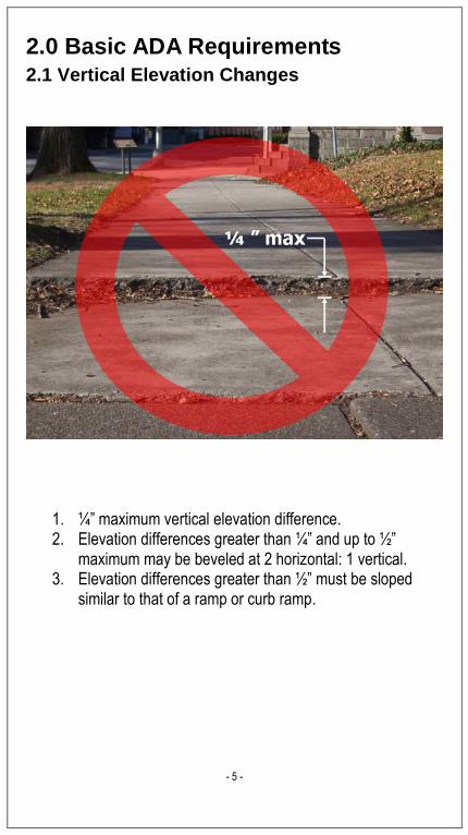
2.0 Basic ADA Requirements 2.1 Vertical Elevation Changes
1. ¼” maximum vertical elevation difference. 2. Elevation differences greater than ¼” and up to ½”
maximum may be beveled at 2 horizontal: 1 vertical. 3. Elevation differences greater than ½” must be sloped
similar to that of a ramp or curb ramp.

- 6 -
2.0 Basic ADA Requirements 2.2 Inlet Openings or Horizontal Gaps
For Inlets located within the pedestrian path: 1. ½” maximum grate openings or horizontal gaps. 2. The long opening must be positioned so that it is
perpendicular to the pedestrian path. See RC-45M. 3. Inlet shall not be located in the pedestrian path for new
construction.
- 7 -
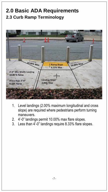
2.0 Basic ADA Requirements 2.3 Curb Ramp Terminology
1. Level landings (2.00% maximum longitudinal and cross slope) are required where pedestrians perform turning maneuvers.
2. 4’-0” landings permit 10.00% max flare slopes. 3. Less than 4’-0” landings require 8.33% flare slopes.
- 8 -
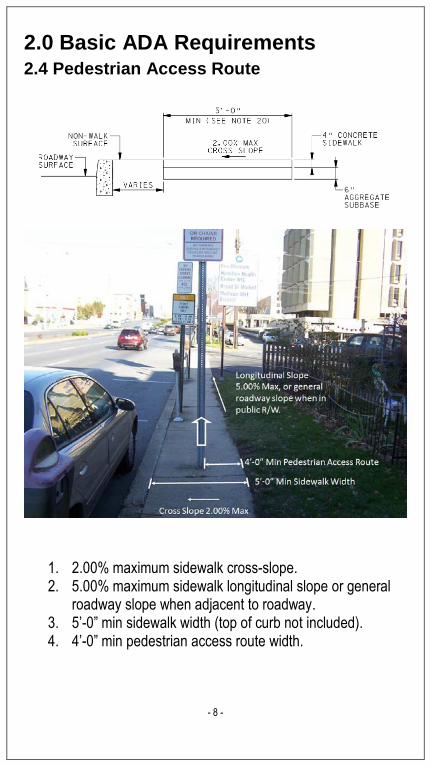
2.0 Basic ADA Requirements 2.4 Pedestrian Access Route
1. 2.00% maximum sidewalk cross-slope. 2. 5.00% maximum sidewalk longitudinal slope or general
roadway slope when adjacent to roadway. 3. 5’-0” min sidewalk width (top of curb not included). 4. 4’-0” min pedestrian access route width.
- 9 -
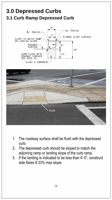
3.0 Depressed Curbs 3.1 Curb Ramp Depressed Curb
1. The roadway surface shall be flush with the depressed curb.
2. The depressed curb should be sloped to match the adjoining ramp or landing slope of the curb ramp.
3. If the landing is indicated to be less than 4’-0”, construct side flares 8.33% max slope.

- 10 -
3.0 Depressed Curbs 3.2 Driveway Depressed Curb
1. For driveways, a 1 ½” maximum vertical lip at the depressed curb is acceptable since it is not designed for pedestrians to cross the lip.
2. The depressed curb for driveways should be sloped to match the adjoining ramp or landing slope of the driveway.

- 11 -
4.0 Curb Ramp Details 4.1 Type 1 Curb Ramp
1. Ramp shall be perpendicular to curb. Note: if the ramp is installed in line with crossing (non-perpendicular), a triangular level landing will be required to prevent an uneven surface for wheel chair users. See section 4.11 for landing details.
2. 4’-0” landing required due to turning maneuver. 3. If landing is indicated to be less than 4’-0”, construct side
flares 8.33% max slope.

- 12 -
4.0 Curb Ramp Details 4.2 Type 1A Curb Ramp
Truncated domes may be arranged in a linear strip (above) if the grade break is less than 5’-0” from the back of curb. If 5’-0” is exceeded, install truncated domes in a radial installation (below) or as a linear strip at the back of curb as shown on sheet 9 of RC-67M.
Note: Patterns on ramp are for illustrative purposes only and are not to be constructed.
Note: Patterns on ramp are for illustrative purposes only and are not to be constructed.

- 13 -
4.0 Curb Ramp Details 4.3 Type 2 Curb Ramp
1. 5’-0” landing required due to turning maneuver. 2. 8.33% maximum ramp slope; 2.00% maximum cross-
slope. 3. For level landings behind depressed curb, adjust slopes
to provide positive drainage.
- 14 -
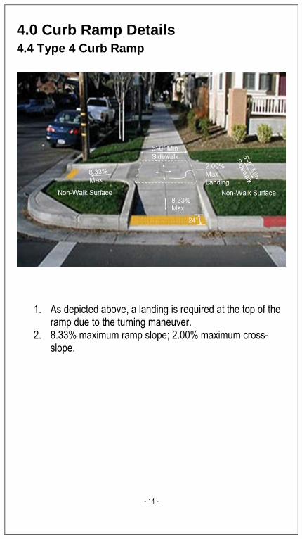
4.0 Curb Ramp Details 4.4 Type 4 Curb Ramp
1. As depicted above, a landing is required at the top of the ramp due to the turning maneuver.
2. 8.33% maximum ramp slope; 2.00% maximum cross-slope.

- 15 -
4.0 Curb Ramp Details 4.5 Type 4A Curb Ramp
1. 8.33% maximum ramp slope; 2.00% maximum cross-slope.
2. As depicted above, a landing is required at the top of the ramp due to the turning maneuver.

- 16 -
4.0 Curb Ramp Details 4.6 Type 6 Curb Ramp
1. 8.33% maximum ramp slope. 2. An intermediate level landing between ramps is required
to perform turning maneuvers.
- 17 -
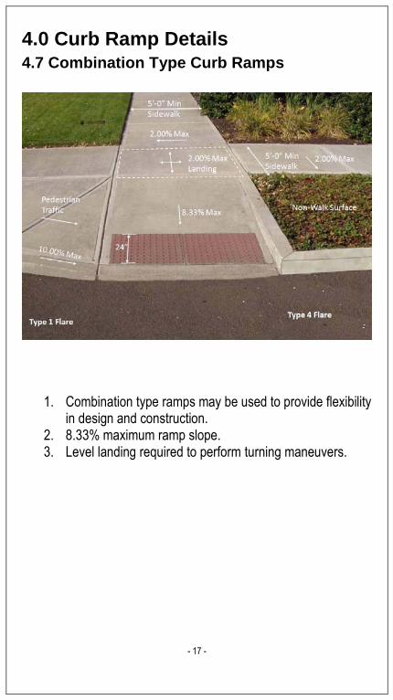
4.0 Curb Ramp Details 4.7 Combination Type Curb Ramps
1. Combination type ramps may be used to provide flexibility in design and construction.
2. 8.33% maximum ramp slope. 3. Level landing required to perform turning maneuvers.
- 18 -
4.0 Curb Ramp Details
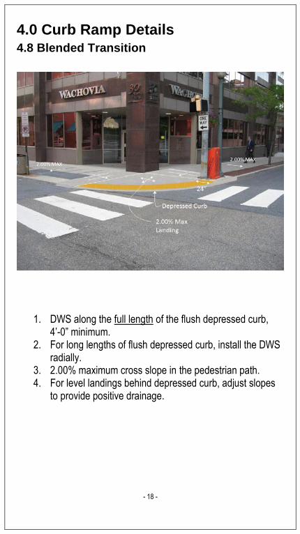
4.8 Blended Transition
1. DWS along the full length of the flush depressed curb, 4’-0” minimum.
2. For long lengths of flush depressed curb, install the DWS radially.
3. 2.00% maximum cross slope in the pedestrian path. 4. For level landings behind depressed curb, adjust slopes
to provide positive drainage.
- 19 -
4.0 Curb Ramp Details
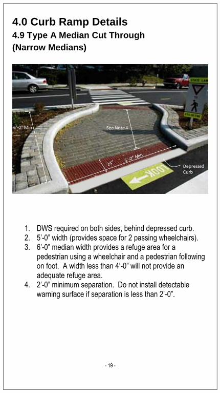
4.9 Type A Median Cut Through
(Narrow Medians)
1. DWS required on both sides, behind depressed curb. 2. 5’-0” width (provides space for 2 passing wheelchairs). 3. 6’-0” median width provides a refuge area for a
pedestrian using a wheelchair and a pedestrian following on foot. A width less than 4’-0” will not provide an adequate refuge area.
4. 2’-0” minimum separation. Do not install detectable warning surface if separation is less than 2’-0”.
- 20 -
4.0 Curb Ramp Details 4.10 Type B Median Cut Through
(Narrow Medians)
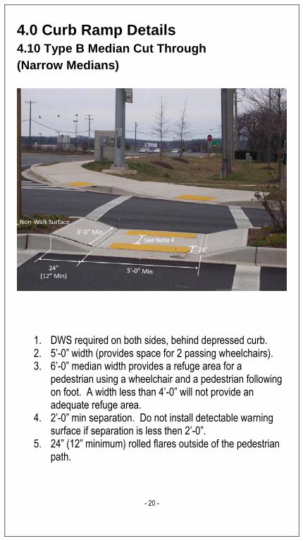
1. DWS required on both sides, behind depressed curb. 2. 5’-0” width (provides space for 2 passing wheelchairs). 3. 6’-0” median width provides a refuge area for a
pedestrian using a wheelchair and a pedestrian following on foot. A width less than 4’-0” will not provide an adequate refuge area.
4. 2’-0” min separation. Do not install detectable warning surface if separation is less then 2’-0”.
5. 24” (12” minimum) rolled flares outside of the pedestrian path.

- 21 -
4.0 Curb Ramp Details 4.11 Triangular Landings for Curb Ramps not perpendicular to the curb
1. To prevent an uneven surface for wheelchair users, a triangular level landing is required at the bottom of the curb ramp.
2. The grade break (start of the ramp) is after the level landing and perpendicular to the travel direction. This will allow for both wheels of the wheelchair to make contact with the grade break at the same time.
3. For level landings behind depressed curb, adjust slopes to provide positive drainage.
Note: Patterns on ramp are for illustrative purposes only and are not to be constructed.

- 22 -
4.0 Curb Ramp Details 4.12 Type 1 Curb Ramps with Shared Landing
1. Type 1 curb ramps may share a landing at the top of the ramp.
2. 8.33% maximum ramp slope; 2.00% maximum cross-slope for ramp and shared landing.
3. 10.00% maximum flare slope with 4’-0” landing depth. 4. If landing is indicated to be less than 4’-0”, construct side
flares 8.33% max slope.

- 23 -
4.0 Curb Ramp Details 4.13 Type 4 Curb Ramps with Shared Landing
1. Type 4 and Type 4A curb ramps may share a landing at the top of the ramp.
2. 8.33% maximum ramp slope; 2.00% maximum cross-slope for ramp and shared landing.
- 24 -
4.0 Curb Ramp Details 4.14 Type 6 Curb Ramps with Shared Landing
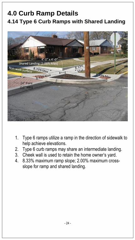
1. Type 6 ramps utilize a ramp in the direction of sidewalk to help achieve elevations.
2. Type 6 curb ramps may share an intermediate landing. 3. Cheek wall is used to retain the home owner’s yard. 4. 8.33% maximum ramp slope; 2.00% maximum cross-
slope for ramp and shared landing.

- 25 -
4.0 Curb Ramp Details 4.15 Transition Curb Ramp Cross Slope to
Match Existing Roadway Profile
1. Transition curb ramp cross slope to match existing roadway profile. Transition to roadway profile as gradually as possible. Do not exceed a cross slope rate of change of 3.00% per linear foot.
2. Complete cross slope transition behind DWS or use 12” square tiles.
3. This allows pedestrians to adjust to roadway profile behind the curb as well as keep storm water out of cart path.

- 26 -
5.0 Driveway Details 5.1 Driveway Type 1
1. DWS only required for high volume driveways (shopping centers, hotels).
2. 5’-0” wide continuous sidewalk with a 2.00% cross slope preferred. At a minimum a continuous 4’-0” wide pedestrian access route shall be maintained.
3. For driveways, a 1 ½” maximum vertical lip at the depressed curb is acceptable since it is not designed for pedestrians to cross the lip.
4. 8.00% maximum algebraic grade difference between roadway slope and driveway ramp slope.
5. 24” (12” minimum) flares when the pedestrian path is separated with a non-walk surface.

- 27 -
5.0 Driveway Details 5.2 Driveway Type 1A
1. DWS only required for high volume driveways (shopping centers, hotels).
2. 5’-0” wide continuous sidewalk with a 2.00% cross slope preferred. At a minimum a continuous 4’-0” wide pedestrian access route shall be maintained.
3. For driveways, a 1 ½” maximum vertical lip at the depressed curb is acceptable since it is not designed for pedestrians to cross the lip.
4. 8.00% maximum algebraic grade difference between roadway slope and driveway ramp slope.
5. 10.00% flares when the pedestrian path is adjacent to driveway flare.

- 28 -
5.0 Driveway Details 5.3 Driveway Type 2
1. DWS only required for high volume driveways (shopping centers, hotels).
2. 5’-0” wide continuous sidewalk with a 2.00% cross slope preferred. At a minimum a continuous 4’-0” wide pedestrian access route shall be maintained.
3. For driveways, a 1 ½” maximum vertical lip at the depressed curb is acceptable since it is not designed for pedestrians to cross the lip.
4. 8.00% maximum algebraic grade difference between roadway slope and driveway ramp slope.
5. As shown, return curb may be used when the pedestrian path is separated with a non-walk surface.

- 29 -
5.0 Driveway Details 5.4 Driveway Type 3A
1. DWS only required for high volume driveways (shopping centers, hotels).
2. 5’-0” wide continuous sidewalk with a 2.00% cross slope preferred. At a minimum a continuous 4’-0” wide pedestrian access route shall be maintained.
3. For driveways, a 1 ½” maximum vertical lip at the depressed curb is acceptable since it is not designed for pedestrians to cross the lip.
4. 8.00% maximum algebraic grade difference between roadway slope and sidewalk slope.
5. Ramp sidewalk down at 8.33% maximum.

- 30 -
5.0 Driveway Details 5.5 Driveway Type 4
1. DWS only required for high volume driveways (shopping centers, hotels).
2. 5’-0” wide continuous sidewalk with a 2.00% cross slope preferred. At a minimum a continuous 4’-0” wide pedestrian access route shall be maintained.
3. For driveways, a 1 ½” maximum vertical lip at the depressed curb is acceptable since it is not designed for pedestrians to cross the lip.
4. 8.00% maximum algebraic grade difference between roadway slope and driveway ramp slope.
5. Transition sidewalk away from curb at a 2:1 minimum as shown to provide additional driveway ramp slope length.

- 31 -
6.0 Surfaces 6.1 Surface Mounted Utilities
1. Existing surface mounted utilities may be in the pedestrian path but must be:
a. stable, firm, slip resistant b. less than ¼” vertical lip c. less than ½” horizontal gap d. meet inlet requirements (See section 2.2) e. outside of the detectable warning surface area
2. Place proposed utilities outside of the pedestrian path.

- 32 -
6.0 Surfaces 6.2 Curb Ramp Changes in Grade
1. Grade difference between roadway slope and curb ramp slope not to exceed 13.33%.
2. Where grade difference exceeds 13.33%, provide a 24” transition strip across the DWS surface so that the grade difference is not exceeded. Transition strip not to exceed 5.00%.
3. The counter slope of the gutter or road at the foot of a curb ramp, landing or blended transition is not to exceed 5.00% maximum slope.
Algebraic grade difference greater than 13.33%
Provide Transition Strip

- 33 -
7.0 Pedestrian Signals 7.1 Pedestrian Signal Heads
1. Install new pushbuttons at 40” to 44” from surface occupied by pedestrian during operation. See TC-8803 for more details.
2. Existing pushbuttons placed between 36” to 46” are accessible.
- 34 -
8.0 Detectable Warning Surfaces 8.1 Approved vs. Not Approved DWS
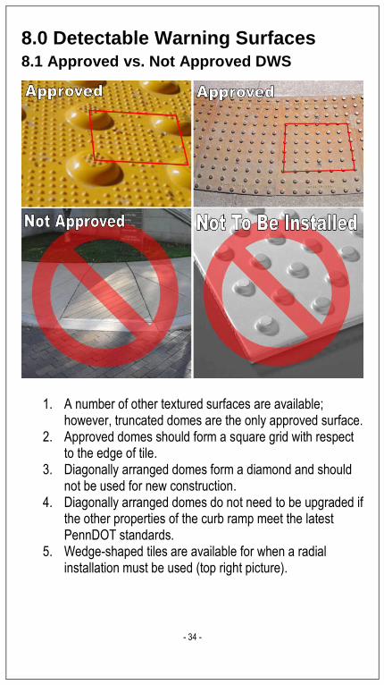
1. A number of other textured surfaces are available; however, truncated domes are the only approved surface.
2. Approved domes should form a square grid with respect to the edge of tile.
3. Diagonally arranged domes form a diamond and should not be used for new construction.
4. Diagonally arranged domes do not need to be upgraded if the other properties of the curb ramp meet the latest PennDOT standards.
5. Wedge-shaped tiles are available for when a radial installation must be used (top right picture).

- 35 -
8.0 Detectable Warning Surfaces
8.2 DWS Placement
1. One corner of the DWS must be at the back of curb. 2. The leading edge must be no more than 5’-0” from the
back of the curb. 3. Place detectable warning surface at back of curb when a
linear installation across the grade break exceeds 5’-0”.
- 36 -
8.0 Detectable Warning Surfaces 8.3 Detectable Warning Surface at Railroad Crossings
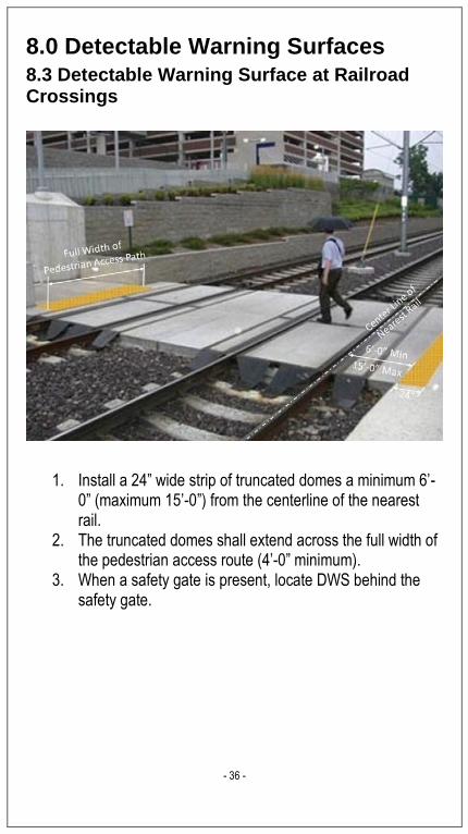
1. Install a 24” wide strip of truncated domes a minimum 6’-0” (maximum 15’-0”) from the centerline of the nearest rail.
2. The truncated domes shall extend across the full width of the pedestrian access route (4’-0” minimum).
3. When a safety gate is present, locate DWS behind the safety gate.

- 37 -
9.0 Retrofit Details 9.1 Sidewalk Additions
1. When the pedestrian path is obstructed, one solution is to provide additional sidewalk around the obstruction to continue the 4’-0” pedestrian access route.
2. Transition sidewalk at a minimum 2:1 rate as shown.
BEFORE
AFTER

- 38 -
9.0 Retrofit Details 9.2 Type 1 Curb Ramp without Landing
Possible Solution –Keep the Type 1 curb ramp and install the required landing.
BEFORE
AFTER

- 39 -
9.0 Retrofit Details 9.3 Type 1 Curb Ramp without Landing
Possible Solution –Reconstruct curb ramp as a Type 2 curb ramp.
BEFORE
AFTER

- 40 -
9.0 Retrofit Details 9.4 Multiple Ramps
Possible Solution - Install Type 6 with intermediate landing.
BEFORE
AFTER

- 41 -
9.0 Retrofit Details 9.5 Missing Ramps
Possible Solution - Install a Type 4 curb ramp. (If maximum ramp slope is exceeded, install Type 6, ramp the sidewalks down to an intermediate landing at the intersection of the sidewalks).
BEFORE
AFTER
- 42 -
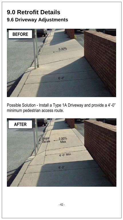
9.0 Retrofit Details 9.6 Driveway Adjustments
Possible Solution - Install a Type 1A Driveway and provide a 4’-0” minimum pedestrian access route.
BEFORE
AFTER
- 43 -
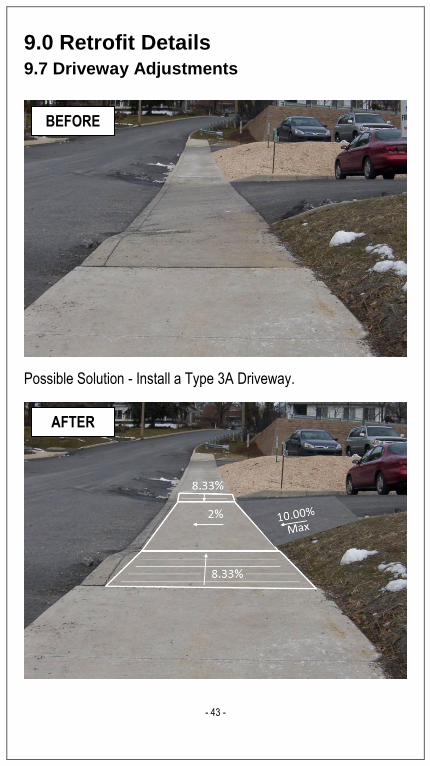
9.0 Retrofit Details
9.7 Driveway Adjustments
Possible Solution - Install a Type 3A Driveway.
BEFORE
AFTER

- 44 -
9.0 Retrofit Details
9.8 Parallel Curb Ramp with Steep Slopes
Partial Type 2 curb ramp installed. Type C inlet replace with a Type M inlet. Ramp begins at inlet.
BEFORE
AFTER

- 45 -
9.0 Retrofit Details
9.9 Removal of Diagonal Curb Ramps
Separate Type 1 curb ramps with adjacent traversable flares.
BEFORE
AFTER

- 46 -
9.0 Retrofit Details
9.10 Adjacent Curb Ramps
Separate Type 1 curb ramps with adjacent traversable flares.
BEFORE
AFTER

- 47 -
9.0 Retrofit Details
9.11 Narrow Sidewalk with Cross Slope Issues
Adjacent Type 2 curb ramps.
BEFORE
AFTER

- 48 -
9.0 Retrofit Details
9.12 Access Pedestrian Pushbuttons
Type 2 curb ramps with cheek wall protecting signal pole foundation and holding soil in place.
BEFORE
AFTER
- 49 -
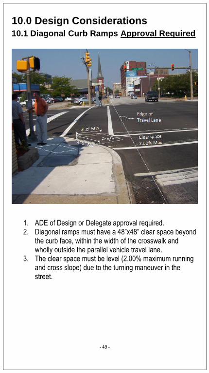
10.0 Design Considerations
10.1 Diagonal Curb Ramps Approval Required
1. ADE of Design or Delegate approval required. 2. Diagonal ramps must have a 48”x48” clear space beyond
the curb face, within the width of the crosswalk and wholly outside the parallel vehicle travel lane.
3. The clear space must be level (2.00% maximum running and cross slope) due to the turning maneuver in the street.

- 50 -
10.0 Design Considerations
10.2 Ramp Lengths Calculations
To calculate ramp length: “G1” Proposed Curb Ramp Slope (%) “G2” Existing Grade (%) “H” Height of Curb (ft)
Ramp Length (ft) = H (G1 – G2)/100 Example #1 0.67 = 8.4’ Example #2 0.5 = 16.7’ Use
(5 – -3)/100 (5-2)/100 Steeper Slope

- 51 -
10.0 Design Considerations
10.3 Ramp Length Chart 5%
1 2 3 4 5 6 7 8 9 10 11 12
12 n/a n/a n/a n/a n/a n/a n/a n/a n/a n/a n/a n/a
11 n/a n/a n/a n/a n/a n/a n/a n/a n/a n/a n/a n/a
10 n/a n/a n/a n/a n/a n/a n/a n/a n/a n/a n/a n/a
9 n/a n/a n/a n/a n/a n/a n/a n/a n/a n/a n/a n/a
8 n/a n/a n/a n/a n/a n/a n/a n/a n/a n/a n/a n/a
7 n/a n/a n/a n/a n/a n/a n/a n/a n/a n/a n/a n/a
6 n/a n/a n/a n/a n/a n/a n/a n/a n/a n/a n/a n/a
5 n/a n/a n/a n/a n/a n/a n/a n/a n/a n/a n/a n/a
4 8.4 n/a n/a n/a n/a n/a n/a n/a n/a n/a n/a n/a
3 4.2 8.4 12.5 n/a n/a n/a n/a n/a n/a n/a n/a n/a
2 2.8 5.6 8.4 11.2 13.9 n/a n/a n/a n/a n/a n/a n/a
1 2.1 4.2 6.3 8.4 10.5 12.5 14.6 n/a n/a n/a n/a n/a
0 1.7 3.4 5.0 6.7 8.4 10.0 11.7 13.4 15.0 n/a n/a n/a
-1 1.4 2.8 4.2 5.6 7.0 8.4 9.8 11.2 12.5 13.9 n/a n/a
-2 1.2 2.4 3.6 4.8 6.0 7.2 8.4 9.6 10.8 12.0 13.1 14.3
-3 1.1 2.1 3.2 4.2 5.3 6.3 7.3 8.4 9.4 10.5 11.5 12.5
-4 1.0 1.9 2.8 3.8 4.7 5.6 6.5 7.5 8.4 9.3 10.2 11.2
-5 0.9 1.7 2.5 3.4 4.2 5.0 5.9 6.7 7.5 8.4 9.2 10.0
-6 0.8 1.6 2.3 3.1 3.8 4.6 5.4 6.1 6.9 7.6 8.4 9.1
-7 0.7 1.4 2.1 2.8 3.5 4.2 4.9 5.6 6.3 7.0 7.7 8.4
-8 0.7 1.3 2.0 2.6 3.3 3.9 4.5 5.2 5.8 6.5 7.1 7.7
-9 0.6 1.2 1.8 2.4 3.0 3.6 4.2 4.8 5.4 6.0 6.6 7.2
-10 0.6 1.2 1.7 2.3 2.8 3.4 3.9 4.5 5.0 5.6 6.2 6.7
-11 0.6 1.1 1.6 2.1 2.7 3.2 3.7 4.2 4.7 5.3 5.8 6.3
-12 0.5 1.0 1.5 2.0 2.5 3.0 3.5 4.0 4.5 5.0 5.4 5.9
"H" CURB HEIGHT (IN)
"G2"
EX
IST
ING
GR
AD
E (
%)
APPROXIMATE RAMP LENGTH (FT)
"G1" 5% SLOPE
CH
AS
ING
GR
AD
EO
PP
OS
ING
GR
AD
E
Use the above chart to determine the approximate ramp length. Step 1. Find the appropriate curb height along the top row. Step 2. Follow the curb height down to the existing grade slope. Step 3. The intersecting value is the approximate ramp length at
the given slope. Step 4. “n/a” indicates that a steeper slope must be used. The
current slope produces a ramp length greater than 15’-0”.
- 52 -
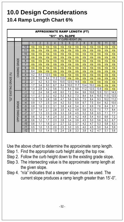
10.0 Design Considerations
10.4 Ramp Length Chart 6%
1 2 3 4 5 6 7 8 9 10 11 12
12 n/a n/a n/a n/a n/a n/a n/a n/a n/a n/a n/a n/a
11 n/a n/a n/a n/a n/a n/a n/a n/a n/a n/a n/a n/a
10 n/a n/a n/a n/a n/a n/a n/a n/a n/a n/a n/a n/a
9 n/a n/a n/a n/a n/a n/a n/a n/a n/a n/a n/a n/a
8 n/a n/a n/a n/a n/a n/a n/a n/a n/a n/a n/a n/a
7 n/a n/a n/a n/a n/a n/a n/a n/a n/a n/a n/a n/a
6 n/a n/a n/a n/a n/a n/a n/a n/a n/a n/a n/a n/a
5 8.4 n/a n/a n/a n/a n/a n/a n/a n/a n/a n/a n/a
4 4.2 8.4 12.5 n/a n/a n/a n/a n/a n/a n/a n/a n/a
3 2.8 5.6 8.4 11.2 13.9 n/a n/a n/a n/a n/a n/a n/a
2 2.1 4.2 6.3 8.4 10.5 12.5 14.6 n/a n/a n/a n/a n/a
1 1.7 3.4 5.0 6.7 8.4 10.0 11.7 13.4 15.0 n/a n/a n/a
0 1.4 2.8 4.2 5.6 7.0 8.4 9.8 11.2 12.5 13.9 n/a n/a
-1 1.2 2.4 3.6 4.8 6.0 7.2 8.4 9.6 10.8 12.0 13.1 14.3
-2 1.1 2.1 3.2 4.2 5.3 6.3 7.3 8.4 9.4 10.5 11.5 12.5
-3 1.0 1.9 2.8 3.8 4.7 5.6 6.5 7.5 8.4 9.3 10.2 11.2
-4 0.9 1.7 2.5 3.4 4.2 5.0 5.9 6.7 7.5 8.4 9.2 10.0
-5 0.8 1.6 2.3 3.1 3.8 4.6 5.4 6.1 6.9 7.6 8.4 9.1
-6 0.7 1.4 2.1 2.8 3.5 4.2 4.9 5.6 6.3 7.0 7.7 8.4
-7 0.7 1.3 2.0 2.6 3.3 3.9 4.5 5.2 5.8 6.5 7.1 7.7
-8 0.6 1.2 1.8 2.4 3.0 3.6 4.2 4.8 5.4 6.0 6.6 7.2
-9 0.6 1.2 1.7 2.3 2.8 3.4 3.9 4.5 5.0 5.6 6.2 6.7
-10 0.6 1.1 1.6 2.1 2.7 3.2 3.7 4.2 4.7 5.3 5.8 6.3
-11 0.5 1.0 1.5 2.0 2.5 3.0 3.5 4.0 4.5 5.0 5.4 5.9
-12 0.5 1.0 1.4 1.9 2.4 2.8 3.3 3.8 4.2 4.7 5.1 5.6
"H" CURB HEIGHT (IN)
"G2"
EX
IST
ING
GR
AD
E (
%)
APPROXIMATE RAMP LENGTH (FT)
"G1" 6% SLOPE
CH
AS
ING
GR
AD
EO
PP
OS
ING
GR
AD
E
Use the above chart to determine the approximate ramp length. Step 1. Find the appropriate curb height along the top row. Step 2. Follow the curb height down to the existing grade slope. Step 3. The intersecting value is the approximate ramp length at
the given slope. Step 4. “n/a” indicates that a steeper slope must be used. The
current slope produces a ramp length greater than 15’-0”.

- 53 -
10.0 Design Considerations
10.5 Ramp Length Chart 7%
1 2 3 4 5 6 7 8 9 10 11 12
12 n/a n/a n/a n/a n/a n/a n/a n/a n/a n/a n/a n/a
11 n/a n/a n/a n/a n/a n/a n/a n/a n/a n/a n/a n/a
10 n/a n/a n/a n/a n/a n/a n/a n/a n/a n/a n/a n/a
9 n/a n/a n/a n/a n/a n/a n/a n/a n/a n/a n/a n/a
8 n/a n/a n/a n/a n/a n/a n/a n/a n/a n/a n/a n/a
7 n/a n/a n/a n/a n/a n/a n/a n/a n/a n/a n/a n/a
6 8.4 n/a n/a n/a n/a n/a n/a n/a n/a n/a n/a n/a
5 4.2 8.4 12.5 n/a n/a n/a n/a n/a n/a n/a n/a n/a
4 2.8 5.6 8.4 11.2 13.9 n/a n/a n/a n/a n/a n/a n/a
3 2.1 4.2 6.3 8.4 10.5 12.5 14.6 n/a n/a n/a n/a n/a
2 1.7 3.4 5.0 6.7 8.4 10.0 11.7 13.4 15.0 n/a n/a n/a
1 1.4 2.8 4.2 5.6 7.0 8.4 9.8 11.2 12.5 13.9 n/a n/a
0 1.2 2.4 3.6 4.8 6.0 7.2 8.4 9.6 10.8 12.0 13.1 14.3
-1 1.1 2.1 3.2 4.2 5.3 6.3 7.3 8.4 9.4 10.5 11.5 12.5
-2 1.0 1.9 2.8 3.8 4.7 5.6 6.5 7.5 8.4 9.3 10.2 11.2
-3 0.9 1.7 2.5 3.4 4.2 5.0 5.9 6.7 7.5 8.4 9.2 10.0
-4 0.8 1.6 2.3 3.1 3.8 4.6 5.4 6.1 6.9 7.6 8.4 9.1
-5 0.7 1.4 2.1 2.8 3.5 4.2 4.9 5.6 6.3 7.0 7.7 8.4
-6 0.7 1.3 2.0 2.6 3.3 3.9 4.5 5.2 5.8 6.5 7.1 7.7
-7 0.6 1.2 1.8 2.4 3.0 3.6 4.2 4.8 5.4 6.0 6.6 7.2
-8 0.6 1.2 1.7 2.3 2.8 3.4 3.9 4.5 5.0 5.6 6.2 6.7
-9 0.6 1.1 1.6 2.1 2.7 3.2 3.7 4.2 4.7 5.3 5.8 6.3
-10 0.5 1.0 1.5 2.0 2.5 3.0 3.5 4.0 4.5 5.0 5.4 5.9
-11 0.5 1.0 1.4 1.9 2.4 2.8 3.3 3.8 4.2 4.7 5.1 5.6
-12 0.5 0.9 1.4 1.8 2.2 2.7 3.1 3.6 4.0 4.4 4.9 5.3
"H" CURB HEIGHT (IN)
"G2"
EX
IST
ING
GR
AD
E (
%)
APPROXIMATE RAMP LENGTH (FT)
"G1" 7% SLOPE
CH
AS
ING
GR
AD
EO
PP
OS
ING
GR
AD
E
Use the above chart to determine the approximate ramp length. Step 1. Find the appropriate curb height along the top row. Step 2. Follow the curb height down to the existing grade slope. Step 3. The intersecting value is the approximate ramp length at
the given slope. Step 4. “n/a” indicates that a steeper slope must be used. The
current slope produces a ramp length greater than 15’-0”.
- 54 -
10.0 Design Considerations
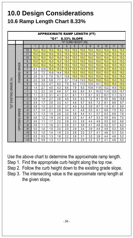
10.6 Ramp Length Chart 8.33%
1 2 3 4 5 6 7 8 9 10 11 12
12 15.0 15.0 15.0 15.0 15.0 15.0 15.0 15.0 15.0 15.0 15.0 15.0
11 15.0 15.0 15.0 15.0 15.0 15.0 15.0 15.0 15.0 15.0 15.0 15.0
10 15.0 15.0 15.0 15.0 15.0 15.0 15.0 15.0 15.0 15.0 15.0 15.0
9 15.0 15.0 15.0 15.0 15.0 15.0 15.0 15.0 15.0 15.0 15.0 15.0
8 15.0 15.0 15.0 15.0 15.0 15.0 15.0 15.0 15.0 15.0 15.0 15.0
7 6.3 12.6 15.0 15.0 15.0 15.0 15.0 15.0 15.0 15.0 15.0 15.0
6 3.6 7.2 10.8 14.4 15.0 15.0 15.0 15.0 15.0 15.0 15.0 15.0
5 2.6 5.1 7.6 10.1 12.6 15.0 15.0 15.0 15.0 15.0 15.0 15.0
4 2.0 3.9 5.8 7.7 9.7 11.6 13.5 15.0 15.0 15.0 15.0 15.0
3 1.6 3.2 4.7 6.3 7.9 9.4 11.0 12.6 14.1 15.0 15.0 15.0
2 1.4 2.7 4.0 5.3 6.6 7.9 9.3 10.6 11.9 13.2 14.5 15.0
1 1.2 2.3 3.5 4.6 5.7 6.9 8.0 9.1 10.3 11.4 12.6 13.7
0 1.1 2.1 3.1 4.1 5.1 6.1 7.1 8.1 9.1 10.1 11.1 12.1
-1 0.9 1.8 2.7 3.6 4.5 5.4 6.3 7.2 8.1 9.0 9.9 10.8
-2 0.9 1.7 2.5 3.3 4.1 4.9 5.7 6.5 7.3 8.1 8.9 9.7
-3 0.8 1.5 2.3 3.0 3.7 4.5 5.2 5.9 6.7 7.4 8.1 8.9
-4 0.7 1.4 2.1 2.8 3.4 4.1 4.8 5.5 6.1 6.8 7.5 8.2
-5 0.7 1.3 1.9 2.6 3.2 3.8 4.4 5.1 5.7 6.3 6.9 7.6
-6 0.6 1.2 1.8 2.4 3.0 3.5 4.1 4.7 5.3 5.9 6.4 7.0
-7 0.6 1.1 1.7 2.2 2.8 3.3 3.9 4.4 4.9 5.5 6.0 6.6
-8 0.6 1.1 1.6 2.1 2.6 3.1 3.6 4.1 4.6 5.2 5.7 6.2
-9 0.5 1.0 1.5 2.0 2.5 2.9 3.4 3.9 4.4 4.9 5.3 5.8
-10 0.5 1.0 1.4 1.9 2.3 2.8 3.2 3.7 4.1 4.6 5.1 5.5
-11 0.5 0.9 1.3 1.8 2.2 2.6 3.1 3.5 3.9 4.4 4.8 5.2
-12 0.5 0.9 1.3 1.7 2.1 2.5 2.9 3.3 3.7 4.1 4.6 5.0
"H" CURB HEIGHT (IN)
"G2"
EX
IST
ING
GR
AD
E (
%)
APPROXIMATE RAMP LENGTH (FT)
"G1" 8.33% SLOPE
CH
AS
ING
GR
AD
EO
PP
OS
ING
GR
AD
E
Use the above chart to determine the approximate ramp length. Step 1. Find the appropriate curb height along the top row. Step 2. Follow the curb height down to the existing grade slope. Step 3. The intersecting value is the approximate ramp length at
the given slope.

- 55 -
10.0 Design Considerations
10.7 Ramp Length Chart 10%
1 2 3 4 5 6 7 8 9 10 11 12
12 15.0 15.0 15.0 15.0 15.0 15.0 15.0 15.0 15.0 15.0 15.0 15.0
11 15.0 15.0 15.0 15.0 15.0 15.0 15.0 15.0 15.0 15.0 15.0 15.0
10 15.0 15.0 15.0 15.0 15.0 15.0 15.0 15.0 15.0 15.0 15.0 15.0
9 8.4 15.0 15.0 15.0 15.0 15.0 15.0 15.0 15.0 15.0 15.0 15.0
8 4.2 8.4 12.5 15.0 15.0 15.0 15.0 15.0 15.0 15.0 15.0 15.0
7 2.8 5.6 8.4 11.2 13.9 15.0 15.0 15.0 15.0 15.0 15.0 15.0
6 2.1 4.2 6.3 8.4 10.5 12.5 14.6 15.0 15.0 15.0 15.0 15.0
5 1.7 3.4 5.0 6.7 8.4 10.0 11.7 13.4 15.0 15.0 15.0 15.0
4 1.4 2.8 4.2 5.6 7.0 8.4 9.8 11.2 12.5 13.9 15.0 15.0
3 1.2 2.4 3.6 4.8 6.0 7.2 8.4 9.6 10.8 12.0 13.1 14.3
2 1.1 2.1 3.2 4.2 5.3 6.3 7.3 8.4 9.4 10.5 11.5 12.5
1 1.0 1.9 2.8 3.8 4.7 5.6 6.5 7.5 8.4 9.3 10.2 11.2
0 0.9 1.7 2.5 3.4 4.2 5.0 5.9 6.7 7.5 8.4 9.2 10.0
-1 0.8 1.6 2.3 3.1 3.8 4.6 5.4 6.1 6.9 7.6 8.4 9.1
-2 0.7 1.4 2.1 2.8 3.5 4.2 4.9 5.6 6.3 7.0 7.7 8.4
-3 0.7 1.3 2.0 2.6 3.3 3.9 4.5 5.2 5.8 6.5 7.1 7.7
-4 0.6 1.2 1.8 2.4 3.0 3.6 4.2 4.8 5.4 6.0 6.6 7.2
-5 0.6 1.2 1.7 2.3 2.8 3.4 3.9 4.5 5.0 5.6 6.2 6.7
-6 0.6 1.1 1.6 2.1 2.7 3.2 3.7 4.2 4.7 5.3 5.8 6.3
-7 0.5 1.0 1.5 2.0 2.5 3.0 3.5 4.0 4.5 5.0 5.4 5.9
-8 0.5 1.0 1.4 1.9 2.4 2.8 3.3 3.8 4.2 4.7 5.1 5.6
-9 0.5 0.9 1.4 1.8 2.2 2.7 3.1 3.6 4.0 4.4 4.9 5.3
-10 0.5 0.9 1.3 1.7 2.1 2.5 3.0 3.4 3.8 4.2 4.6 5.0
-11 0.4 0.8 1.2 1.6 2.0 2.4 2.8 3.2 3.6 4.0 4.4 4.8
-12 0.4 0.8 1.2 1.6 1.9 2.3 2.7 3.1 3.5 3.8 4.2 4.6
"H" CURB HEIGHT (IN)
"G2"
EX
IST
ING
GR
AD
E (
%)
APPROXIMATE RAMP LENGTH (FT)
"G1" 10% SLOPE
CH
AS
ING
GR
AD
EO
PP
OS
ING
GR
AD
E
Use the above chart to determine the approximate ramp length. Step 1. Find the appropriate curb height along the top row. Step 2. Follow the curb height down to the existing grade slope. Step 3. The intersecting value is the approximate ramp length at
the given slope.