Pencil-Beam Single-point-fed Dirac Leaky-Wave Antenna on a ...
4
IEEE ANTENNAS AND WIRELESS PROPAGATION LETTERS, VOL. **, NO. *, ****** 2016 1 Pencil-Beam Single-point-fed Dirac Leaky-Wave Antenna on a Transmission-Line Grid Ayman H. Dorrah, Student Member, IEEE and George V. Eleftheriades, Fellow, IEEE Abstract—Leaky-wave antennas (LWAs) are widely used as single-point-fed linear antenna arrays. The extension of LWAs to 2D implies that they can be used as single-point-fed 2D antenna arrays without requiring a complex feeding network. However, generating a pencil beam from 2D LWAs is not straightforward and due care has to be taken for the design of the LWA. On the other hand, transmission-line (TL) grids have demonstrated interesting behaviors, such as an effective negative refractive index and growing of evanescent waves. In this paper, a single- point-fed TL-grid 2D Dirac leaky-wave antenna (DLWA) design is proposed that generates a pencil beam at both broadside and slightly tilted angles. The TL-grid unit cell is analytically treated in light of its scattering and impedance matrices. The optimized TL-grid unit cell is shown to exhibit a closed bandgap in the dispersion relation which is also linearly varying with frequency (hence it is a DLWA). The proposed 2D DLWA design is fabricated and the experimental results are presented. Index Terms—Transmission line grids, broadside radiation, Dirac leaky-wave antennas, single-point-fed, Γ-point operation. I. I NTRODUCTION There is ever increasing demand for low profile antennas with highly directive pencil beams especially for satellite communications. Two-dimensional (2D) antenna arrays are typically used for this purpose because of their low profile and capability to produce highly directive pencil beams with both azimuth and elevation beam-scanning capabilities. However, in traditional designs, 2D antenna arrays require complex feeding networks to excite each element of the antenna array with the correct phase and power level. Another challenge in 2D arrays is the inherent losses in the complex feeding networks especially at high frequencies. To eliminate the feeding network entirely, there has been a lot of research interest in using metamaterials to design 2D leaky-wave antenna (LWA) arrays which typically have high gain and low profile. A single-point-fed 2D LWA design was proposed and experimentally demonstrated in [1]. The antenna is center-fed and due to the azimuthal symmetry, it produces a conical beam with elevation angle that is scanned by sweeping the input frequency. However, the produced conical beam is not suitable for applications that require high directivity. On the other hand, holographic techniques have been proposed to generate a pencil beam from single-point-fed 2D holographic LWAs [2], [3]. A surface wave must be excited in order for these designs to work properly and achieve the required interference pattern. Furthermore, the proposed holographic designs do not achieve a true broadside operation and are The authors are with the Edward S. Rogers, Sr. Department of Electrical and Computer Engineering, University of Toronto, Toronto, ON M5S 3G4, Canada (e-mail: [email protected]). -d x /2 d x /2 -d y /2 d y /2 Origin Z o Z o Z o Z o Z o , β Z o , β Z o , β Z o , β y x Fig. 1: The unit cell model of an ideal 2D TL-grid unit cell terminated with Z o . not meant for beam scanning; moreover, they are difficult to design. From the previous discussion, it is evident that the single- point-fed 2D LWAs proposed in the literature generate a conical beam or only generate a pencil beam at a fixed radiation direction. Thus, a single-point-fed 2D LWA design that operates in transmission-line (TL) form, capable of gener- ating a directive scannable pencil beam would be a desirable addition to the state of the art. In this paper, we report the design, fabrication and experimental testing of a low-profile corner-fed 2D LWA that is based on TL-grids capable of generating a highly directive pencil beam with continuous scanning through broadside. It is shown that the dispersion relation of the optimized TL-grid unit cell is linearly varying with frequency with a closed bandgap at the Γ-point. This means that the TL-grid unit cell exhibits a Dirac dispersion and the resulting 2D antenna design is a Dirac leaky-wave antenna (DLWA) analogous to the photonic crystal antenna proposed in [4]. The antenna is operated in its dominant mode, thus, it can be fed by a transmission line allowing for relatively wideband operation and a decent scanning range with frequency. II. ANALYSIS OF THE TL- GRID UNIT CELL The model of an ideal TL-grid unit cell terminated with Z o is presented in Fig. 1. Using transmission-line theory [5], the S-parameters of the TL-grid unit cell can be analytically obtained as: S = 1 2 χψ -χ/ψ 1 χ/ψ 1 1 -ψ/χ 1 ψ/χ χ/ψ 1 -χ/ψ 1 1 ψ/χ 1 -ψ/χ (1) where χ = e -jβdx/2 and ψ = e -jβdy/2 , β is the propaga- tion constant of the transmission lines used, d x and d y are the dimensions of the TL-grid unit cell along the x and y arXiv:1607.01433v1 [physics.class-ph] 5 Jul 2016
Transcript of Pencil-Beam Single-point-fed Dirac Leaky-Wave Antenna on a ...
IEEE ANTENNAS AND WIRELESS PROPAGATION LETTERS, VOL. **, NO. *, ****** 2016 1
Pencil-Beam Single-point-fed Dirac Leaky-Wave Antennaon a Transmission-Line Grid
Ayman H. Dorrah, Student Member, IEEE and George V. Eleftheriades, Fellow, IEEE
Abstract—Leaky-wave antennas (LWAs) are widely used assingle-point-fed linear antenna arrays. The extension of LWAs to2D implies that they can be used as single-point-fed 2D antennaarrays without requiring a complex feeding network. However,generating a pencil beam from 2D LWAs is not straightforwardand due care has to be taken for the design of the LWA. Onthe other hand, transmission-line (TL) grids have demonstratedinteresting behaviors, such as an effective negative refractiveindex and growing of evanescent waves. In this paper, a single-point-fed TL-grid 2D Dirac leaky-wave antenna (DLWA) designis proposed that generates a pencil beam at both broadsideand slightly tilted angles. The TL-grid unit cell is analyticallytreated in light of its scattering and impedance matrices. Theoptimized TL-grid unit cell is shown to exhibit a closed bandgapin the dispersion relation which is also linearly varying withfrequency (hence it is a DLWA). The proposed 2D DLWA designis fabricated and the experimental results are presented.
Index Terms—Transmission line grids, broadside radiation,Dirac leaky-wave antennas, single-point-fed, Γ-point operation.
I. INTRODUCTION
There is ever increasing demand for low profile antennaswith highly directive pencil beams especially for satellitecommunications. Two-dimensional (2D) antenna arrays aretypically used for this purpose because of their low profile andcapability to produce highly directive pencil beams with bothazimuth and elevation beam-scanning capabilities. However, intraditional designs, 2D antenna arrays require complex feedingnetworks to excite each element of the antenna array withthe correct phase and power level. Another challenge in 2Darrays is the inherent losses in the complex feeding networksespecially at high frequencies.
To eliminate the feeding network entirely, there has been alot of research interest in using metamaterials to design 2Dleaky-wave antenna (LWA) arrays which typically have highgain and low profile. A single-point-fed 2D LWA design wasproposed and experimentally demonstrated in [1]. The antennais center-fed and due to the azimuthal symmetry, it produces aconical beam with elevation angle that is scanned by sweepingthe input frequency. However, the produced conical beam isnot suitable for applications that require high directivity. Onthe other hand, holographic techniques have been proposed togenerate a pencil beam from single-point-fed 2D holographicLWAs [2], [3]. A surface wave must be excited in orderfor these designs to work properly and achieve the requiredinterference pattern. Furthermore, the proposed holographicdesigns do not achieve a true broadside operation and are
The authors are with the Edward S. Rogers, Sr. Department of Electricaland Computer Engineering, University of Toronto, Toronto, ON M5S 3G4,Canada (e-mail: [email protected]).
-dx/2
dx/2-dy/2
dy/2
Origin
Zo
Zo
Zo
Zo
Zo, β Zo, β
Zo, β Zo, β
y
x
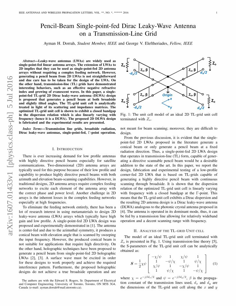
Fig. 1: The unit cell model of an ideal 2D TL-grid unit cellterminated with Zo.
not meant for beam scanning; moreover, they are difficult todesign.
From the previous discussion, it is evident that the single-point-fed 2D LWAs proposed in the literature generate aconical beam or only generate a pencil beam at a fixedradiation direction. Thus, a single-point-fed 2D LWA designthat operates in transmission-line (TL) form, capable of gener-ating a directive scannable pencil beam would be a desirableaddition to the state of the art. In this paper, we report thedesign, fabrication and experimental testing of a low-profilecorner-fed 2D LWA that is based on TL-grids capable ofgenerating a highly directive pencil beam with continuousscanning through broadside. It is shown that the dispersionrelation of the optimized TL-grid unit cell is linearly varyingwith frequency with a closed bandgap at the Γ-point. Thismeans that the TL-grid unit cell exhibits a Dirac dispersion andthe resulting 2D antenna design is a Dirac leaky-wave antenna(DLWA) analogous to the photonic crystal antenna proposed in[4]. The antenna is operated in its dominant mode, thus, it canbe fed by a transmission line allowing for relatively widebandoperation and a decent scanning range with frequency.
II. ANALYSIS OF THE TL-GRID UNIT CELL
The model of an ideal TL-grid unit cell terminated withZo is presented in Fig. 1. Using transmission-line theory [5],the S-parameters of the TL-grid unit cell can be analyticallyobtained as:
S =1
2χψ
−χ/ψ 1 χ/ψ 1
1 −ψ/χ 1 ψ/χχ/ψ 1 −χ/ψ 1
1 ψ/χ 1 −ψ/χ
(1)
where χ = e−jβdx/2 and ψ = e−jβdy/2, β is the propaga-tion constant of the transmission lines used, dx and dy arethe dimensions of the TL-grid unit cell along the x and y
arX
iv:1
607.
0143
3v1
[ph
ysic
s.cl
ass-
ph]
5 J
ul 2
016

IEEE ANTENNAS AND WIRELESS PROPAGATION LETTERS, VOL. **, NO. *, ****** 2016 2
Frequency (GHz)4.5 4.75 5 5.25 5.5 5.75 6 6.25 6.5
S-p
aram
eter
s (d
B)
-16
-14
-12
-10
-8
-6
-4
-2
0|S
mm|
|Snm
|
Frequency (GHz)4.5 4.75 5 5.25 5.5 5.75 6 6.25 6.5
(S-p
aram
eter
s)o
-200
-150
-100
-50
0
50
100
150
200 (Smm
)o
(Snm
)o
Fig. 2: Ideal S-parameter response of the symmetric TL-gridunit cell with d = 40mm and βd = 2π at 5.48GHz.
Frequency (GHz)4.5 4.75 5 5.25 5.5 5.75 6 6.25 6.5
Z-p
aram
eter
s
02468
101214161820
|Zmm
|/Zo
|Znm
|/Zo
Frequency (GHz)4.5 4.75 5 5.25 5.5 5.75 6 6.25 6.5
(Z-p
aram
eter
s)o
-200
-150
-100
-50
0
50
100
150
200 (Zmm
)o
(Znm
)o
Fig. 3: Ideal Z-parameter response of a symmetric TL-gridunit cell with d = 40mm and βd = 2π at 5.48GHz.
directions, respectively. Assuming a symmetric TL-grid unitcell with dx = dy = d, the S-matrix in (1) can be simplifiedto:
Sd×d =1
2e−jβd
−1 1 1 11 −1 1 11 1 −1 11 1 1 −1
(2)
The magnitude and phase of Smm and Snm (m 6= n) fora symmetric TL-grid unit cell are plotted in Fig. 2. It is clearthat the magnitude of all the scattering parameters is equalto 6dB regardless of the dimensions of the TL-grid unit cell,which means that an incident voltage wave at one of the portsis distributed equally between the 4 ports of the TL-grid unitcell. In addition, the voltage waves leaving the ports of theTL-grid unit cell are in phase with the incident voltage waveat the frequency where βd = 2π. This frequency will bereferred to as the Γ-point frequency because at that frequency,an infinitely periodic TL-grid structure has a single operationpoint in the 2D dispersion relation which is at the Γ-point [6].
The impedance matrix of the symmetric TL-grid unit cellcan be derived from the S-matrix in (2) [5]:
Zd×d = Zoejβd
e2jβd − 1
δ 1 1 11 δ 1 11 1 δ 11 1 1 δ
(3)
where δ = 2cos(βd)− 1.The magnitude and phase plots of the Z-parameters of
the symmetric TL-grid unit cell are presented in Fig. 3. Atthe Γ-point frequency, the Z-matrix elements are infinite inmagnitude. This singularity is associated with the vanishingdenominator (e2jβd − 1) when d = 2π/β.
Fig. 4: The voltage and current distributions across a single-point-fed 10 × 10 TL-grid array structure where the feedingpoint is highlighted by the blue circle.
III. 2D SINGLE-POINT FED TL-GRID ARRAY STRUCTURES
The effect of the singularity is demonstrated by simulating asingle-point-fed 10×10 array constructed from the symmetricTL-grid unit cell at the Γ-point frequency using AdvancedDesign System (ADS). The transmission lines used in thecircuit model are assumed to be lossless and the 2D arrayis single-point-fed from the corner using a voltage source.The resulting voltage distribution across the 2D TL-grid arraystructure is presented in Fig. 4a where the voltage is sampledat the individual unit cells’ centers and boundaries. It isobserved that the voltage distribution is uniform across theentire sampling locations within the 2D structure even thoughthe grid is excited from a single point. It is crucial to highlightthat the voltage distribution is uniform only at the individualunit cells’ centers and boundaries and is nonuniform at otherlocations inside the unit cells.
On the other hand, the current distribution across the samearray structure is depicted in Fig. 4b with sampling at theindividual unit cells boundaries. It is clear that the currentdistribution is not uniform. The current is maximum at thefeeding location at the corner of the 2D structure and decays asthe wave propagates away from the feeding point. The obviousdiscrepancy between the current and voltage profiles is a directconsequence of the singularity in the Z-matrix at the Γ-pointwhere there is no longer a direct relation between the voltagesand currents at the individual unit cell boundaries.
IV. 2D SINGLE-POINT FED DLWA DESIGN
The symmetric TL-grid unit cell is modified into a radiatingTL-grid unit cell by adding patches and curving the transmis-sion lines as shown in Fig. 5a. This opens the bandgap at theΓ-point which is subsequently closed by adding a metallic viaand a square patch at the center of the unit cell. The simulatedfull-wave dispersion relation of the TL-grid LWA unit cell isdepicted in Fig. 5b which confirms that the bandgap at theΓ-point is successfully closed. The closure of the bandgapmeans that the resulting unit cell is capable of generating apencil beam at and around broadside. The bandgap is closed byachieving accidental degeneracy of the eigenmodes of interestat the Γ-point analogous to what has been proposed in [7]. It isalso noticeable that the dispersion relation around the Γ-pointvaries linearly with frequency which means that the conesformed are Dirac cones and the corresponding antenna designis a Dirac leaky-wave antenna (DLWA) [4]. It is important tomention that this DLWA TL-grid unit cell can be modeled

IEEE ANTENNAS AND WIRELESS PROPAGATION LETTERS, VOL. **, NO. *, ****** 2016 3
(a) Unit cell top view
π/4π/8
kyd
y
0-π/8-π/4π/4π/80k
xd
x
-π/8-π/4
5.6
5.4
6.2
6
5.8
Fre
quen
cy (
GH
z)(b) Dispersion relation
Fig. 5: Radiating TL-grid unit cell: (a) Top view of the unitcell (b) Full-wave simulated dispersion relation using HFSS.Unit cell dimensions: dx = dy = 40mm, dcenter patch =5.5mm, Wx = Wy = 4mm, Lm = 3.75mm, Dv = 0.5mm,Lp = 6.75mm, Wp = 19mm, Ls = 2mm, Ws = 0.5mm,ao = bo = 45o and substrate thickness = 1.575mm on aRogers RT/duriod 5880 substrate.
Fig. 6: Full-wave eigenmode electric field magnitude [V/m]simulation results using HFSS at the Γ-point frequency(5.77GHz) for the unit cell shown in Fig. 5a.
by modifying the circuit model in Fig. 1 to account forthe radiation of the unit cell and the effect of the patchesand the metallic vias. However, it was preferred to close thebandgap by making the eigenmodes of interest at the Γ-pointaccidentally degenerate rather than using an equivalent circuitmodel.
There is also a flat (deaf) band at the Γ-point frequency.Thus, at the Γ-point, there are 3 eigenmodes which were madeaccidentally degenerate and their field profiles are presentedin Fig. 6. It is noticeable that the 1st and 2nd eigenmodefields resemble the electric fields present in a microstrip patchantenna at resonance. The patches are added at the unit cellboundaries because this is where the voltage distribution ofa single-point-fed 2D array is uniform (Fig. 4a). In addition,the transmission lines of the unit cell in Fig. 5a are curved toenhance radiation from the 3rd eigenmode. The 3 eigenmodesat the Γ-point are required to have balanced radiation levelsto ensure a uniform gain when the beam is frequency scannedaround broadside. In the proposed design, the radiation fromthe 3 eigenmodes is optimized to be as balanced as possiblewithout reopening the bandgap in the dispersion relation.
The optimized radiating unit cell is arranged in a 6 × 6array and the fabricated structure is shown in Fig. 7. This 2Dstructure is excited from the bottom-left corner using a singlecoaxial feed coming from below the 2D DLWA. An OpenCircuit (OC) parallel stub is used at the input to match thedesign to the 50Ω coaxial line. As for the terminations fromthe top and right sides of the design, the 2D DLWA design iseffectively terminated to the Bloch impedance value.
Fig. 7: Top view photo of the fabricated 2D DLWA (unit cellin Fig. 5a) with dimensions 254.75× 254.75× 1.575 mm.
Frequency (GHz)5 5.2 5.4 5.6 5.8 6 6.2
S11
(dB
)
-16
-14
-12
-10
-8
-6
-4
-2
0Measured Simulated
(a) S11 responseFrequency (GHz)
5 5.2 5.4 5.6 5.8 6 6.2
Rad
iatio
n E
ffici
ency
(%
)
0102030405060708090
100
(b) Radiation Efficiency
Fig. 8: (a) Measured and simulated S11 response (b) Simulatedradiation efficiency (%).
The 2D DLWA was left open circuited from the bottomand left sides (surrounding the coaxial feed) to avoid losingpower directly to the terminations without ever going to theDLWA. Thus, the realized gain by leaving the bottom and leftsides OC is increased as opposed to using Bloch impedanceterminations (resistors) without severely perturbing proper TL-grid operation.
The full-wave simulated and measured S11 are plotted inFig. 8a. The simulated and measured S11 are below 8dB and10dB, respectively, throughout the frequency range of interest.On the other hand, Fig. 8b depicts the simulated radiationefficiency of this 2D DLWA and its behavior with frequency.The calculated radiation efficiency is between 60%-90% inthe frequency range of interest and is 63.5% at broadsidewhere the remaining unradiated power is absorbed in theterminations.
At the Γ-point (5.75GHz), the measured gain is comparedagainst the full-wave simulated realized gain in Fig. 9. Ameasured gain of 17.5dB is achieved compared to a simulatedone of 18.6dB. The two gain plots also show the same trendof the sidelobes and the overall beam shape.
The actual measured gain and simulated realized gain pat-terns of this 2D DLWA are plotted in Fig. 10 in 40dB-scale foran E-Plane cut (φ = 45o) where the beam is frequency scannedfrom 5-6.2GHz (θmax = −31o to 11.5o). It is clear thatthis 2D DLWA is capable of forward and backward radiationwith a uniform gain level and without breaking at broadsidewhich is an indication of successful closing of the bandgap.The measured realized gain remains fairly uniform as thebeam is frequency scanned in the backward radiation direction.However, as the beam is scanned in the forward direction, thereis a decrease in gain because of the emergence of grating lobesat higher frequencies. The measured gain plots in this E-Plane

IEEE ANTENNAS AND WIRELESS PROPAGATION LETTERS, VOL. **, NO. *, ****** 2016 4
θo
-180 -135 -90 -45 0 45 90 135 180
Gai
n (d
B)
-20
-15
-10
-5
0
5
10
15
20MeasuredSimulated
(a) E-plane (φ = 45o)θ
o-180 -135 -90 -45 0 45 90 135 180
Gai
n (d
B)
-20
-15
-10
-5
0
5
10
15
20Measured Simulated
(b) H-plane (φ = 135o)
Fig. 9: Measured gain and simulated realized gain in 40dB-scale at broadside (5.75GHz).
-16-12-8-4048121620 dB
90o
60o
30o0o
-30o
-60o
-90o
-120o
-150o
180o 150o
120o
(a) 5.0GHz
-16-12-8-4048121620 dB
90o
60o
30o0o
-30o
-60o
-90o
-120o
-150o
180o 150o
120o
(b) 5.2GHz
-16-12-8-4048121620 dB
90o
60o
30o0o
-30o
-60o
-90o
-120o
-150o
180o 150o
120o
(c) 5.4GHz
-16-12-8-4048121620 dB
90o
60o
30o0o
-30o
-60o
-90o
-120o
-150o
180o 150o
120o
(d) 5.6GHz
-16-12-8-4048121620 dB
90o
60o
30o0o
-30o
-60o
-90o
-120o
-150o
180o 150o
120o
(e) 5.9GHz
-16-12-8-4048121620 dB
90o
60o
30o0o
-30o
-60o
-90o
-120o
-150o
180o 150o
120o
(f) 6.2GHz
Fig. 10: E-plane (φ = 45o) measured gain (solid black) andsimulated realized gain (dotted blue) in 40dB-scale.
cut are shifted by θ = +3.5o to partially account for angularmisalignments during testing.
Furthermore, a comparison between the measured gain andthe simulated realized gain is presented in Table I for thesame frequency range. Indeed both have the same level ofgain and performance with some discrepancies that can beattributed to misalignments during testing. In contrast to thedesign presented in [1] which generates a conical beam, theproposed DLWA TL-grid design is capable of generating ahighly directive pencil beam at both broadside and tilted anglesbecause of the closed bandgap in the dispersion relation, thecorner feed used and other important factors such as the largerunit cell size of the TL-grid unit cell when compared to typicalmetamaterial unit cell sizes and the open circuit terminationsadopted around the coaxial feed. The generated pencil beamis frequency scanned in the E-plane of the 2D DLWA with an
TABLE I: Actual and simulated gains for the E-Plane cut.
Frequency (GHz) Simulated Realized Gain Measured Gain5.0GHz 16.4dB 15.5dB5.2GHz 17.6dB 18.4dB5.4GHz 18.2dB 17.7dB5.6GHz 18.8dB 18.0dB5.75GHz 18.6dB 17.5dB5.9GHz 16.7dB 15.1dB6.2GHz 11.3dB 11.3dB
acceptable level of matching and because of the establishedDirac cones the scanning of the beam is linear with frequency.On the other hand, the proposed TL-grid DLWA design isanalogous to the photonic crystal DLWA design presented in[4] where both designs employ the accidental degeneracy ofthe eigenmodes of interest at the Γ-point to establish the Diraccones and have continuous beam steering through broadside.However, the DLWA design presented in [4] is 1D, dielectricbased and generates a fan beam whereas the proposed TL-grid DLWA design here is 2D, transmission-line based andgenerates a pencil beam.
V. CONCLUSION
In this paper, we have used S-parameter analysis to showhow to design a TL grid with a uniform voltage distribution(magnitude and phase) at its nodes. It has also been shownby circuit simulations that this uniform voltage distribution ismaintained at the Γ-point even for a single-point-fed 2D array.The corresponding TL-grid unit cell has been modified into aradiating unit cell and it has been shown that it is possibleto close the bandgap in the dispersion relation by establishingaccidental degeneracy of the eigenmodes of interest at the Γ-point. The dispersion relation of the radiating unit cell has alsobeen shown to exhibit a closed bandgap with cones that arelinearly varying with frequency which are the characteristicsof a Dirac dispersion. Based on this, a TL-grid 2D Dirac LWAdesign was presented. The antenna elements were added at theunit cell boundaries to ensure the uniformity of the individualantenna elements’ excitation level even when fed from a singlefeeding point. The fabricated 2D DLWA is single-point-fedfrom the corner, thus, does not require a complex feeding net-work. In addition, the proposed design can achieve continuousbeam scanning from backward to forward radiation directionswith a linear variation with frequency and without breakingat broadside. This experimentally demonstrates the possibilityof using the TL-grids as single-point-fed 2D DLWAs wherethe underlying grid achieves the required amplitude and phaseexcitation of the antenna elements.
REFERENCES
[1] C. A. Allen, C. Caloz, and T. Itoh, “Leaky-waves in a metamaterial-based two-dimensional structure for a conical beam antenna application,”in Microwave Symposium Digest, 2004 IEEE MTT-S International, vol. 1,June 2004, pp. 305–308 Vol.1.
[2] B. Fong, J. Colburn, J. Ottusch, J. Visher, and D. Sievenpiper, “Scalarand tensor holographic artificial impedance surfaces,” Antennas andPropagation, IEEE Transactions on, vol. 58, no. 10, pp. 3212–3221, Oct2010.
[3] G. Minatti, M. Faenzi, E. Martini, F. Caminita, P. De Vita, D. Gonzalez-Ovejero, M. Sabbadini, and S. Maci, “Modulated metasurface antennasfor space: Synthesis, analysis and realizations,” Antennas and Propaga-tion, IEEE Transactions on, vol. 63, no. 4, pp. 1288–1300, April 2015.
[4] M. Memarian and G. V. Eleftheriades, “Dirac leaky-wave antennas forcontinuous beam scanning from photonic crystals,” Nature communica-tions, vol. 6, 2015.
[5] D. M. Pozar, Microwave Engineering. John Wiley & Sons, 2009, ch. 4.[6] T. Andrade, A. Grbic, and G. V. Eleftheriades, “Growing evanescent
waves in continuous transmission-line grid media,” Microwave and Wire-less Components Letters, IEEE, vol. 15, no. 2, pp. 131–133, Feb 2005.
[7] X. Huang, Y. Lai, Z. H. Hang, H. Zheng, and C. Chan, “Dirac conesinduced by accidental degeneracy in photonic crystals and zero-refractive-index materials,” Nature materials, vol. 10, no. 8, pp. 582–586, 2011.